EP4011562A1 - Justiervorrichtung - Google Patents
Justiervorrichtung Download PDFInfo
- Publication number
- EP4011562A1 EP4011562A1 EP20213918.4A EP20213918A EP4011562A1 EP 4011562 A1 EP4011562 A1 EP 4011562A1 EP 20213918 A EP20213918 A EP 20213918A EP 4011562 A1 EP4011562 A1 EP 4011562A1
- Authority
- EP
- European Patent Office
- Prior art keywords
- module
- adjusting device
- positioning
- working
- working module
- Prior art date
- Legal status (The legal status is an assumption and is not a legal conclusion. Google has not performed a legal analysis and makes no representation as to the accuracy of the status listed.)
- Granted
Links
Images




Classifications
-
- B—PERFORMING OPERATIONS; TRANSPORTING
- B25—HAND TOOLS; PORTABLE POWER-DRIVEN TOOLS; MANIPULATORS
- B25F—COMBINATION OR MULTI-PURPOSE TOOLS NOT OTHERWISE PROVIDED FOR; DETAILS OR COMPONENTS OF PORTABLE POWER-DRIVEN TOOLS NOT PARTICULARLY RELATED TO THE OPERATIONS PERFORMED AND NOT OTHERWISE PROVIDED FOR
- B25F5/00—Details or components of portable power-driven tools not particularly related to the operations performed and not otherwise provided for
- B25F5/02—Construction of casings, bodies or handles
Definitions
- the invention relates to an adjusting device according to the preamble of claim 1.
- the invention relates to a modular unit according to the preamble of claim 8.
- the invention also relates to a hand-held working device according to the preamble of claim 11.
- a working module for example an oil pump
- a drive shaft of a hand-held implement for example a motor chain saw
- Simple tools such as screwdrivers or pipes are also used here.
- Hand-held tools are generally used outside of a workshop. Such tools are usually not available there.
- the invention is based on the object of providing an adjustment device for the relative positioning of a working module relative to the drive shaft of a hand-held implement for driving the working module, which enables simple positioning and adjustment of the working module with respect to the drive shaft of the hand-held implement.
- the invention is based on the object of providing a modular unit comprising a working module and an adjustment device for the relative positioning of the working module relative to the drive shaft of a hand-held implement for driving the working module, which allows for simple positioning and adjustment of the working module with respect to the drive shaft of the hand-held implement allows.
- the invention is based on the object of providing a hand-held working device comprising a module unit and a drive shaft, in which simple positioning and adjustment of the working module with respect to the drive shaft of the hand-held working device is possible.
- the adjustment device has a module positioning device for positioning the adjustment device relative to the working module.
- the adjusting device can be positioned on the working module in a defined position in relation to the working module.
- the invention provides that the adjustment device has a shaft positioning device for positioning the adjustment device relative to the drive shaft.
- the fact that the adjustment device is positioned relative to the working module and at the same time relative to the drive shaft results in a defined relative positioning of the working module and drive shaft.
- the adjustment device aligns the work module relative to the drive shaft.
- the adjusting device is designed in such a way that it is suitable for covering the working module.
- the adjusting device is designed in particular in such a way that it is suitable for covering a gear mechanism of the working module.
- the adjusting device can be designed as a cover for the working module.
- the adjustment device has a dual function. On the one hand, it can be used for the relative positioning of the working module and drive shaft during the adjustment and subsequent fixing of the working module relative to the drive shaft, and on the other hand, the adjusting device can then be used to cover the working module.
- the adjustment device can always be carried along as part of the working device and is not useless after the adjustment of the working module has been completed, since it then serves as a cover for the working module.
- the adjusting device is not carried along as a largely superfluous tool when the hand-held working device is in use, but also fulfills a function during operation of the hand-held working device.
- the adjusting device in its function as a cover for the working module, can be mounted on the working module in a simple manner. As a result, the adjustment device is always available at a fixed location. Should the adjustment device be required in its function as an adjustment device for the relative positioning of the work module and the drive shaft, the adjustment device is ready to hand. In this way, a simple relative positioning of the working module and the drive shaft is possible.
- the module positioning device advantageously has angular positioning elements.
- the angular positioning elements are expediently suitable for angular positioning of the adjusting device relative to the working module with respect to rotation about the axis of rotation in the operating position of the adjusting device.
- the angular position of the working module and the adjustment device relative to one another can be specified in a defined manner.
- the module positioning device has a radial positioning element.
- the radial positioning element is expediently suitable for radial positioning of the adjustment device relative to the working module with respect to a radial direction running perpendicular to the axis of rotation when the adjustment device is in the operating position.
- the radial position of the working module and the adjustment device relative to one another can be specified in a defined manner.
- the module positioning device advantageously has an axial positioning element.
- the axial positioning element is expediently suitable for positioning the adjustment device relative to the working module in the operating position of the adjustment device with respect to an axial direction of the axis of rotation.
- the relative position of the working module and the adjustment device with respect to the axial direction can be specified in a defined manner.
- the adjusting device is expediently designed in such a way that it is suitable for attachment to the working module. As a result, the adjustment device can be carried along on the work module in an uncomplicated manner.
- the adjustment device has an adjustment side and a cover side.
- the adjustment device is designed in such a way that the working module can be covered with the cover side when it is in a covered state.
- the adjustment device is expediently designed in such a way that, in an adjustment state, the working module can be positioned relative to the drive shaft by means of the adjustment device.
- the adjustment side advantageously faces the working module in the adjustment state.
- This design of the adjustment device allows the double function of the adjustment device to be implemented in a simple manner.
- the adjusting device can, for example, cover the working module with a flat area on the cover side, in particular in the area of the drive shaft. This prevents disruptive components used for adjustment protruding in the direction of the drive shaft during operation of the hand-held power tool.
- the adjusting device expediently has a securing element for mounting on the working module.
- the adjusting device can be adjusted by means of the securing element the work module must be kept in such a way that the adjustment device can be carried safely on the work module.
- the adjustment device is designed such that it can be secured in the covered state by means of the securing element on the working module in a rotationally secure manner with respect to the axis of rotation and with respect to the axial direction in a non-removable manner.
- the adjustment device is part of a modular unit which, in addition to the adjustment device, includes a working module.
- the module unit expediently has a module positioning means for positioning the adjustment device relative to the working module.
- the module positioning means comprises the module positioning device on the adjustment device and a module positioning unit on the working module.
- the module positioning device of the adjustment device includes the angular positioning elements.
- the module positioning unit comprises angular positioning parts.
- the angular positioning elements and the angular positioning parts work together for the angular positioning of the adjustment device relative to the working module with respect to a rotation about the axis of rotation.
- the module positioning device of the adjustment device includes the radial positioning element.
- the module positioning unit includes a radial positioning part.
- the radial positioning element and the radial positioning part work together for the radial positioning of the adjustment device relative to the working module with respect to a displacement of the adjusting device and working module in a plane perpendicular to the axis of rotation.
- the module positioning device of the adjustment device includes the axial positioning element.
- the module positioning unit includes a module stop. The axial positioning element and the module stop advantageously work together to position the adjustment device relative to the working module with respect to the axial direction of the axis of rotation.
- the modular unit expediently has a securing means.
- the securing means comprises a securing element of the adjustment device and a securing part of the working module.
- the securing element cooperates with the securing part to secure against a relative movement of the adjusting device and working module against one another in the axial direction.
- the securing element interacts with the securing part to secure against a rotational movement of the adjusting device relative to the working module with respect to the axis of rotation.
- the securing means has an undercut with respect to the axial direction to secure against a relative movement of the adjustment device and working module against one another in the axial direction.
- the securing means for securing against a rotational movement of the adjusting device relative to the working module has a cantilever arm which protrudes radially with respect to the axis of rotation and forms an undercut in the circumferential direction around the axis of rotation, which corresponds to a securing projection of the working module.
- the securing part of the working module is part of the module positioning unit and can be used both for securing the adjusting device on the working module and for positioning the working module and adjusting device relative to one another. This allows space to be saved. In addition, the manufacture of the adjustment device of the module unit is simpler.
- the module unit is part of a hand-held working device, which also includes a drive shaft for driving the working module.
- the modular unit has a shaft positioning means for positioning the adjustment device relative to the drive shaft.
- the shaft positioning means expediently comprises the shaft positioning device of the adjustment device and a shaft positioning unit on the drive shaft.
- the shaft positioning device is expediently arranged on the adjustment side of the adjustment device.
- the adjustment side of the adjustment device faces the drive shaft in the adjustment state of the hand-held working device.
- the cover side of the adjusting device is expediently facing the drive shaft when the hand-held working device is in the covered state.
- the working module includes a gear with a first gear component and a second gear component.
- the second gear component is intended to interact with the first gear component.
- the first transmission component is arranged on the drive shaft of the hand-held implement.
- the second transmission component is expediently mounted in a module housing of the working module.
- the working module is advantageously aligned relative to the drive shaft by means of the adjustment device in such a way that the first gear component and the second gear component mesh to form the gear.
- the first transmission component and the second transmission component engage in one another in such a way that the transmission functions.
- the adjustment device can be used to adjust the transmission.
- the adjusting device, the working module and the drive shaft are designed in such a way that the second transmission component can be swiveled in a swiveling range about the axis of rotation in the state of adjustment.
- the adjustment device, the working module and the drive shaft are designed in such a way that the second transmission component can be pivoted in the adjustment state in a pivoting range around the first transmission component.
- the adjusting device, the working module and the drive shaft are designed in such a way that the first gear component and the second gear component to form the gear in any pivoted position of the Swivel range mesh.
- the first transmission component and the second transmission component expediently engage in one another in such a way that the transmission functions.
- the first gear component and the second gear component to form the gear engage in each other in each pivoting position of the pivoting range in such a way that the gear works.
- the module housing can be pivoted into a fixing position when the transmission is functioning and can be fixed in the fixing position on a housing of the hand-held implement. In this way, a simple adjustment of the gear and a simple assembly of the working module on the housing of the hand-held working device is possible.
- the working module is expediently fixed in the fixing position on the housing of the hand-held working device.
- the adjusting device is held in the covered state by means of the securing means on the working module that is in the fixing position.
- the adjusting device covers the transmission of the working module in the covered state.
- the hand-held tool 3 is a motor chain saw in the embodiment. However, the hand-held tool can also be a brush cutter, a blower, a sprayer or a similar hand-held tool.
- the hand-held tool 3 is battery-operated in the exemplary embodiment. However, it can also be a hand-held working device operated with an internal combustion engine.
- the hand-held working device 3 includes a working module 2.
- the working module 2 is an oil pump.
- the oil pump delivers oil to lubricate a saw chain of the motor chain saw.
- the working module 2 is driven by a drive shaft 4 of the hand-held working device 3 .
- the drive shaft 4 of the hand-held implement 3 rotates about an axis of rotation 50.
- the axis of rotation 50 extends in an axial direction 49.
- the work module 2 it can also be any other type of work module that can be driven by the drive shaft of the hand-held implement.
- the work module 2 comprises a gear 5.
- the gear 5 comprises a first gear component 24 and a second gear component 25.
- the first gear component 24 of the work module 2 is arranged on the drive shaft 4 of the hand-held implement 3.
- the first transmission component 24 is connected to the drive shaft 4 in a torque-proof manner.
- the first transmission component 24 is arranged coaxially to the drive shaft 4 .
- the first transmission component 24 rotates about the axis of rotation 50 during operation of the hand-held power tool 3 .
- the first transmission component 24 has a helical thread on its peripheral side.
- the helical thread is part of a worm shaft.
- the gear 5 is a worm gear in the embodiment.
- the second transmission component 25 is rotatably mounted in a module housing 26 of the working module 2 ( 2 ).
- the second transmission component 25 can be rotated about an axis of rotation 51 .
- the axis of rotation 51 extends in a direction 52 of the axis of rotation.
- the direction of the axis of rotation 52 is oriented transversely, in the exemplary embodiment perpendicularly, to the axial direction 49 of the axis of rotation.
- the second gear component 24 has teeth on its peripheral side.
- the teeth of the second gear component 25 correspond to the helical thread of the first gear component 24.
- the second gear component 25 is a gear wheel.
- the second transmission component 25 is also referred to as a toothed shaft.
- the second transmission component 25 is the worm wheel of the transmission 5 designed as a worm gear.
- the working module 2 is fastened to a housing 27 of the hand-held working device 3 by means of the fastening means 28 .
- the fastening means 28 comprises two screws and thus corresponding threads in the housing 27.
- the fastening means 28 is inserted through an opening 29 in the module housing 26 of the Work module 2 plugged. Then the fastener 28 is screwed into the thread of the housing 27 . Any other type of attachment is also conceivable.
- the working module 2 is fixed on the housing 27 of the hand-held working device 3 by means of the fastening means 28 .
- the fastening means 28 presses the working module 2 against the housing 27 of the hand-held working device 3.
- the working module 2 When the working module 2 is fixed in this way on the housing 27 of the hand-held working device 3, the working module 2 must be positioned relative to the drive shaft 4 in such a way that the first transmission component 24 and the second Transmission component 25 interlock in such a way that the transmission 5 is formed in a proper, functional manner. For this purpose, before the working module 2 is fixed in place, the working module 2 must be aligned relative to the drive shaft 4 .
- An adjusting device 1 is provided for the relative positioning of working module 2 and drive shaft 4 .
- the adjustment device 1 is part of the hand-held tool 3.
- the adjustment device 1 and the work module 2 together form an in 2 illustrated module unit 40.
- the adjusting device 1 has a module positioning device 10.
- the module positioning device 10 is used to position the adjusting device 1 relative to the working module 2.
- the module positioning device 10 comprises a first angular positioning element 11 and a second angular positioning element 12.
- the first angular positioning element 11 and the second angular positioning element 12 are used for angular positioning of the adjusting device 1 relative to the working module 2 a rotation about the axis of rotation 50 in the position of use of the adjusting device 1 suitable.
- the adjusting device 1 rests on the working module 2 .
- the axis of rotation 50 intersects the adjustment device 1 in the operating position of the adjustment device 1.
- the Winkelpositionieriata 11 and 12 are formed in the embodiment as tabs.
- the adjusting device 1 has a base body 22.
- the base body 22 has a plane perpendicular to the axis of rotation 50 an outer contour.
- the angular positioning elements 11 and 12 protrude beyond the outer contour.
- the outer contour of the base body 22 of the adjusting device 1 is circular.
- the angular positioning elements 11 and 12 have openings 58 that pass through in the axial direction 49 .
- a component of the working module 2 that corresponds to the opening 58 can be inserted through the opening 58 .
- the first angular positioning element 11 is opposite the second angular positioning element 12 with respect to the axis of rotation 50 in the operating position of the adjusting device 1 .
- the working module 2 has a first angular positioning part 15 and a second angular positioning part 16.
- the first angular positioning part 15 of the working module 2 corresponds to the first angular positioning element 11 of the adjusting device 1.
- the second angular positioning part 16 of the working module 2 corresponds to the second angular positioning element 12 of the adjusting device 1.
- the adjustment device 1 has an adjustment state 9 .
- the adjustment state 9 is also an adjustment state of the module unit 40.
- the adjustment state 9 is also an adjustment state of the hand-held working device 3.
- the first angular positioning part 15 of the working module 2 is arranged in the first angular positioning element 11 of the adjusting device 1.
- the first angular positioning part 15 is inserted into the first angular positioning member 11 .
- the second angular positioning part 16 of the working module 2 is arranged in the second angular positioning element 12 of the adjusting device 1 .
- the second angular positioning part 16 is inserted into the second angular positioning member 12 .
- the adjustment device 1 is secured against rotation about the axis of rotation 50 relative to the working module 2 .
- the angular positioning part 15 , 16 of the working module 2 protrudes in the axial direction 49 in the direction of the adjusting device 1 with respect to a base body 53 of the working module 2 .
- the first angular positioning element 11 and the second angular positioning element 12 are arranged asymmetrically with respect to the axis of rotation 50 on the base body 22 of the adjusting device 1 .
- the first angular positioning element 11 and the second angular positioning element 12 and the axis of rotation 50 then do not lie on a straight line perpendicular to the axis of rotation 50.
- the second angular positioning element 12 is not arranged in the same plane as the axis of rotation and the first angular positioning element 11.
- the first angular positioning part 15 and the second angular positioning part 16 are then arranged corresponding to the first angular positioning element 11 and the second angular positioning element 12 on the work module 2 .
- the working module 2 comprises a module positioning unit 14.
- the module unit 40 has a module positioning means 41.
- the module positioning means 41 is used to position the adjusting device 1 relative to the working module 2.
- the module positioning means 41 comprises the module positioning device 10 on the adjusting device 1 and the module positioning unit 14 on the working module 2 .
- the first angular positioning part 15 of the working module 2 and the second angular positioning part 16 of the working module 2 are part of the module positioning unit 14 of the working module 2.
- the adjusting device 1 is not only in relation to a rotation of Working module 2 and adjusting device 1 secured with respect to the axis of rotation 50, but also an adjustment of the relative position of adjusting device 1 and working module 2 with respect to a radial direction 48 is achieved.
- the radial direction 48 runs radially to the axis of rotation 50.
- the radial direction 48 is oriented perpendicularly to the axis of rotation 50.
- the module positioning device 10 has an in 2 shown radial positioning element 19.
- the radial positioning element 19 is suitable for positioning the adjustment device 1 relative to the working module 2 in the operating position of the adjustment device 1 with respect to the radial direction 48 .
- the body 22 of the adjusting device 1 has an outer peripheral side 23 .
- the outer peripheral side 23 corresponds to the outer surface of a cylinder.
- the radial positioning element 19 is formed by a part of the outer peripheral side 23 of the base body 22, as well as in FIGS figures 2 and 3 shown.
- the radial positioning element 19 runs closed around the axis of rotation 50 .
- the radial positioning element 19 is circular in the exemplary embodiment.
- the radial positioning element 19 rests against the working module 2 in the adjustment state 9 .
- the module positioning unit 14 of the working module 2 includes a radial positioning part 54.
- the radial positioning part 54 corresponds to the radial positioning element 19.
- the radial positioning part 54 is formed on an inner circumference 55 of the module housing 27.
- the inner circumference 55 has the shape of the inside of a hollow cylinder.
- the radial positioning part 54 runs closed around the axis of rotation 50 .
- the radial positioning part 54 runs in a circle around the axis of rotation 50 .
- the radial positioning part 54 of the working module 2 is a radial stop for the radial positioning element 19 of the adjustment device 1. In the adjustment state 9, the radial positioning element 19 rests against the radial positioning part 54.
- the radial positioning element 19 and the radial positioning part 54 work together to position the adjustment device 1 relative to the working module 2 with respect to the radial direction 48 .
- the adjusting device 1 is not only in relation to a rotation of working module 2 and adjusting device 1 with respect to the axis of rotation 50 and with respect to a displacement of working module 2 and adjusting device 1 relative to each other with respect to the radial direction 48 secured, but also an adjustment of the relative position of adjusting device 1 and work module 2 with respect to the axial direction 49 is achieved.
- the module positioning device 10 has one in the Figures 3 and 4 illustrated first axial positioning element 13.
- the first axial positioning element 13 is suitable for positioning the adjustment device 1 relative to the working module 2 in the operating position of the adjustment device 1 with respect to the axial direction 49 of the axis of rotation 50 .
- a web 32 is arranged at the in 4 shown outer peripheral side 23 of the base body 22, arranged.
- the web 32 protrudes beyond the base body 22 in the radial direction 48 .
- the web 32 protrudes in the radial direction 48 beyond the outer peripheral side 23 of the base body 22 .
- the web 32 is delimited in the axial direction 49 by the first axial positioning element 13 .
- the first axial positioning element 13 is part of the web 32.
- the first axial positioning element 13 is the end face of the web 32.
- the first axial positioning element protrudes in the radial direction 48 beyond the base body 22.
- the first axial positioning element 13 is in the in 3 shown adjustment state 9 facing the work module 2.
- the first axial positioning element 13 rests against the working module 2 in the adjustment state 9 .
- the adjusting device 1 has a total of two first axial positioning elements 13 .
- the two first axial positioning elements 13 are opposite one another with respect to the axis of rotation 50 .
- the two first axial positioning elements 13 are diametrically opposite one another on the outer peripheral side 23 of the base body 22 .
- the further first axial positioning element 13 is designed analogously to the first axial positioning element 13 already described.
- the adjusting device 1 has a second axial positioning element 18 .
- the second axial positioning element 18 is also used for the relative positioning of the adjusting device 1 and the working module 2 in the operating position of the adjusting device 1 with respect to the axial direction 49 of the axis of rotation 50.
- the second axial positioning element 18 is formed on the first angular positioning element 11 and on the second angular positioning element 12.
- the second axial positioning element 18 projects beyond the base body 22 of the adjusting device 1 in the radial direction 48 . That second axial positioning element 18 protrudes beyond the outer peripheral side 23 in the radial direction 48 .
- the second axial positioning element 18 is formed by the end face of the angle positioning element 11 or 12 .
- the second axial positioning element 18 faces the working module 2 in the adjustment state 9 . In the adjustment state 9 , the adjustment device 1 rests against the working module 2 with the second axial positioning element 18 .
- two second axial positioning elements 18 are provided.
- the two second axial positioning elements 18 are opposite one another with respect to the axis of rotation 50 .
- the two second axial positioning elements 18 are diametrically opposite one another on the outer peripheral side 23 of the base body 22 .
- first axial positioning elements 13 and second axial positioning elements 18 are arranged alternately on the outer circumferential side 23 of the base body 22 of the adjusting device 1 .
- the second axial positioning element 18 is arranged at an angular distance of 80° to 100°, in particular 90°, from the first axial positioning element 13 with respect to the axis of rotation 50 .
- the first axial positioning elements 13 and the second axial positioning elements 18 are arranged at equal angular distances from one another.
- the first axial positioning element 13 and the second axial positioning element 18 are arranged at the same height with respect to the axial direction 49 .
- the first axial positioning element 13 and the second axial positioning element 18 together form a contact surface of the adjustment device 1 for contact with the working module 2.
- the first axial positioning element 13 is part of the module positioning device 10.
- the second axial positioning element 18 is also part of the module positioning device 10.
- the module positioning device 10 comprises the first angular positioning element 11, the second angular positioning element 12, the radial positioning element 19, the two first axial positioning elements 13 and the two second axial positioning elements 18 ( Figures 3 and 4 ).
- the module positioning unit 14 of the working module 2 comprises a module stop 17.
- the module stop 17 corresponds to the first axial positioning element 13.
- the module stop 17 also corresponds to the second axial positioning element 18.
- the module stop 17 is an edge of the working module 2 that runs around the axis of rotation 50
- the module stop 17 runs in a circle around the axis of rotation 50 .
- the module stop 17 runs closed around the axis of rotation 50 .
- the first axial positioning element 13 and the second axial positioning element 18 rest against the module stop 17. This defines the relative positioning of the working module 2 and the adjustment device 1 with respect to the axial direction 49 of the axis of rotation 50 .
- the axial positioning element 13, 18 and the module stop 17 work together.
- the module positioning unit 14 comprises the first angular positioning element 15, the second angular positioning element 16, the module stop 17 and the radial positioning part 54.
- the adjusting device 1 has a in the 3 and 4 shaft positioning device 20 shown.
- the shaft positioning device 20 is used to position the adjusting device 1 relative to the drive shaft 4.
- the shaft positioning device 20 protrudes in the axial direction 49 beyond the base body 22 of the adjusting device 1.
- the shaft positioning device 20 faces the working module 2 .
- a shaft positioning unit 21 is arranged on the drive shaft 4 .
- the shaft positioning device 20 and the shaft positioning unit 21 together form a shaft positioning means 43.
- the shaft positioning means 43 serves to position the adjusting device 1 relative to the drive shaft 4.
- the shaft positioning means 43 comprises the shaft positioning device 20 of the adjusting device 1 and the shaft positioning unit 21 on the drive shaft 4.
- the drive shaft 4 has an open end 33 .
- the open end 33 is arranged at the longitudinal end of the drive shaft 4 .
- the drive shaft 4 is hollow at the open end 33 .
- the drive shaft 4 has the shape of a hollow cylinder.
- the shaft positioning unit 21 is part of the working module 2 .
- the shaft positioning unit 21 is arranged on the open end 33 of the drive shaft 4 .
- the shaft positioning unit 21 is plugged into the open end 33 of the drive shaft 4 .
- the shaft positioning unit 21 is connected to the drive shaft 4 in a torque-proof manner.
- the shaft positioning unit 21 is part of the first transmission component 24 of the work module 2.
- the first transmission component 24 of the working module 2 engages in the drive shaft 4 of the hand-held working device 3 .
- the first transmission component 24 is inserted into the open end 33 of the drive shaft 4 .
- the first transmission component 24 is connected to the drive shaft 4 in a torque-proof manner.
- the first transmission component 24 has an end opening 34.
- the end opening 34 is formed on a longitudinal end of the first transmission component 24 that faces away from the drive shaft 4.
- the end opening 34 opens in the axial direction 49.
- the axis of rotation 50 runs through the end opening 34.
- the end opening 34 of the first transmission component 24 is part of the shaft positioning unit 21.
- the shaft positioning device 20 and the shaft positioning unit 21 work together for the relative positioning of the adjusting device 1 and the drive shaft 4 .
- Shaft positioning device 20 of the adjusting device 1 and the first transmission component 24 together.
- the shaft positioning device 20 is inserted into the end opening 34 of the first gear component 24 .
- the shaft positioning device 20 of the adjusting device 1 and the shaft positioning unit 21 on the drive shaft 4 correspond to one another.
- the end opening 34 and the shaft positioning device 20 correspond to each other.
- the shaft positioning device 20 has a substantially cylindrical outer contour. In a plane perpendicular to the axis of rotation 50, the outer contour of the shaft positioning device 20 is essentially circular.
- the otherwise cylindrical shaft positioning device 20 has slots 39 in the axial direction 49 . Because of the slots 39, the shaft positioner 20 is not completely rigid.
- the shaft locator 20 may be pushed into the end opening 34 of the first gear assembly 24 .
- the shaft positioning device 20 presses outwards in the radial direction 48 against the first gear component 24. In this way, the adjustment device 1 is held clamped in the first gear component 24.
- the axis of rotation 50 runs centrally through the essentially circular outer contour of the shaft positioning device 20.
- the shaft positioning device 20 is arranged eccentrically to the circular outer peripheral side 23 of the base body 22 of the adjusting device 1.
- the shaft positioning device 20 has a maximum distance d max measured radially to the axis of rotation 50 from an inner peripheral side 35 of the base body 22 of the adjusting device 1 .
- the shaft positioning device 20 has a minimum distance d min , measured radially with respect to the axis of rotation 50 , from the inner peripheral side 35 of the base body 22 of the adjusting device 1 .
- the second transmission component 25 is arranged in the adjustment state 9 in the area of the maximum distance d max .
- the area of the maximum distance d max of the adjustment device 1 is arranged above the second transmission component 25 .
- the second Transmission component 25 is mounted in the module housing 26 below the area of the maximum distance d max of the adjusting device 1.
- the working module 2 is aligned relative to the drive shaft 4 by means of the adjustment device 1 in such a way that the first gear component 24 and the second gear component 25 mesh to form the gear 5 .
- the adjustment device 1 is connected to the working module 2 in a rotationally fixed manner.
- the adjusting device 1 and the working module 2 form the modular unit 40.
- the adjusting device 1 is aligned relative to the drive shaft 4 by the shaft positioning means 43.
- the working module 2 is aligned relative to the adjusting device 1 by the module positioning means 41 .
- the drive shaft 4 is aligned relative to the work module 2 .
- the first gear component 24 which is connected in a torque-proof manner to the drive shaft 4 , is aligned relative to the second gear component 25 mounted in the module housing 26 of the working module 2 .
- the adjustment device 1 can be pivoted about the axis of rotation 50 together with the working module 2 .
- the adjustment device 1, the working module 2 and the drive shaft 4 are designed in such a way that the second transmission component 25 can be pivoted in the adjustment state 9 in a pivoting range about the axis of rotation 50.
- the adjustment device 1, the working module 2 and the drive shaft 4 are designed in such a way that the second gear component 25 can be pivoted in the adjustment state 9 in a pivoting range about the first gear component 24.
- the first gear component 24 and the second gear component 25 mesh to form the gear 5 in each pivoting position of the pivoting range.
- the pivoting range is ⁇ 5°, in particular ⁇ 10°, preferably ⁇ 20°, with respect to a fixed position of the working module 2 on the housing 27 of the hand-held working device 3 .
- the module housing 26 can be pivoted into the fixing position and can be fixed in the fixing position on the housing 27 of the hand-held power tool 3 .
- the fastening means 28 can be pushed through the in 1 shown opening 29 in the module housing 26 of the working module 2 in the associated thread in the housing 27 of the hand-held working device 3 be screwed.
- the gear 5 works in every swivel position.
- the teeth of the second gear component 25 mesh with the helical thread of the first gear component 24.
- the second gear component 25 is driven by the first gear component 24.
- the adjusting device 1 is applied to the working module 2 in the adjusting state 9 for mounting the working module 2 on the housing 27 of the hand-held working device 3 .
- the working module 2 is connected to the drive shaft 4 of the hand-held working device 3 via the shaft positioning unit 21 of the working module 2 .
- the positioning or adjustment of the working module 2 on the housing 27 takes place by pivoting the working module 2 into the fixing position. After the working module 2 has been fixed to the housing 27, the adjustment device 1 can be removed from the adjustment state 9.
- the adjusting device 1 is designed in such a way that the adjusting device 1 is suitable for covering the working module 2 .
- the adjusting device 1 is particularly suitable for covering the transmission 5 .
- the adjusting device 1 can be arranged on the module housing 26 of the working module 2 in such a way that the transmission 5 is completely covered.
- the gear 5 is included in the modular unit 40 consisting of the adjusting device 1 and the working module 2 .
- the gear 5 is surrounded by the adjusting device 1 and the module housing 26 .
- the opening in the module housing 26 for the drive shaft 4 is filled and covered by the drive shaft 4 and the first transmission component 24 .
- the adjustment device 1 is designed in such a way that it is suitable for attachment to the working module 2 .
- the adjusting device 1 includes a securing element 30.
- the securing element 30 is used to hold the adjusting device 1 on the work module 2.
- the adjusting device 1 is designed such that it can be secured by means of the securing element 30 on the working module 2 so as to be non-rotatable with respect to the axis of rotation 50 and non-removable with respect to the axial direction 49 .
- the adjustment device 1 has an adjustment side 6 .
- the adjustment device 1 has a cover side 7 .
- the adjustment side 6 and the covering side 7 point in opposite directions. This is particularly in 8 shown.
- the figures 2 and 3 show the adjustment state 9 of the hand-held tool 3 or the adjustment device 1.
- the adjustment side 6 of the adjustment device 1 faces the working module 2.
- the working module 2 can be positioned relative to the drive shaft 4 by means of the adjustment device 1 .
- the adjustment device 1 is designed such that in the adjustment state 9 the working module 2 can be positioned relative to the drive shaft 4 by means of the adjusting device 1 , with the adjustment side 6 facing the working module 2 .
- the covering state 8 is also the covering state of the adjusting device 1.
- the covering state 8 is also the covering state of the modular unit 40 made up of adjusting device 1 and working module 2.
- In the covering state 8 is the working module 2 with the covering side 7 of the adjusting device 1 coverable.
- In the covering state 8 the covering side 7 of the adjusting device 1 faces the working module 2 .
- the adjusting device 1 is designed in such a way that the working module 2 can be covered with the covering side 7 in the covering state 8 .
- the shaft positioning device 20 is arranged on the adjustment side 6 of the adjustment device 1 .
- the adjustment side 6 of the adjustment device 1 faces the drive shaft 4 .
- the cover side 7 of the adjusting device 1 faces the drive shaft 4 .
- the modular unit 40 comprises a securing means 42.
- the securing means 42 comprises the securing element 30 of the adjusting device 1 and a securing part 31 of the working module 2.
- the securing element 30 acts to secure against a relative movement of the adjusting device 1 and working module 2 in the axial direction 49 the fuse part 31 together.
- the securing element 30 interacts with the securing part 31 to secure against a rotational movement of the adjustment device 1 relative to the working module 2 with respect to the axis of rotation 50 .
- the securing element 30 interacts with the securing part 31 to secure against displacement of the adjustment device 1 relative to the working module 2 with respect to the radial direction 48 .
- the adjusting device 1 is held on the working module 2 in the covering state 8 .
- the hand-held working device 3 can be operated without losing the adjusting device 1 . If the adjustment device 1 is required to replace the working module 2 or to readjust the working module 2 on the housing 27 of the hand-held working device 3 , the adjusting device 1 is ready to hand in the covered state 8 .
- the adjustment device 1 In the covering state 8 , the adjustment device 1 is held on the working module 2 by means of the securing means 42 . In the covering state 8 , the adjusting device 1 covers the transmission 5 of the working module 2 .
- the adjusting device 1 When the adjusting device 1 is in the operating position, the adjusting device 1 is in the covering state 8 or in the adjusting state 9.
- the base body 22 of the adjusting device 1 has a center plate 36.
- the inner peripheral side 35 of the base body 2 runs around the center plate 36 in a closed manner.
- the middle plate 36 forms a bottom of the adjusting device 1.
- the center plate 36 forms a support for the Shaft positioning device 20.
- the center plate 36 is free of components.
- the adjusting device 1 is flat in the area of the center plate 36 .
- the adjusting device 1 is free of components in the area of the center plate, which protrude beyond the center plate 36 in the axial direction 49.
- the drive shaft 4 is undisturbed by the adjusting device 1 in the covering state 8.
- the first gear component 24 arranged on the drive shaft 4 is undisturbed by the adjusting device 1 in the covering state 8.
- a rotation of the drive shaft 4 is possible in the covering state 8 undisturbed by the adjusting device 1.
- the adjusting device 1 has a flange 37 running around the axis of rotation 50 .
- the flange 37 projects beyond the base body 22 of the adjusting device 1 in the radial direction 48 .
- the flange 37 protrudes beyond the outer peripheral side 23 of the base body 22 in the radial direction 48 .
- the flange 37 rests against a projection 38 of the module housing 26 of the working module 2 in the covering state 8 .
- the projection 38 of the module housing 26 runs closed around the axis of rotation 50 .
- the projection 38 of the module housing 26 corresponds to the flange 37 of the adjusting device 1.
- the projection 38 is circular in the axial direction 49.
- the working module 2 is completely covered by the adjusting device 1 due to the interaction of the flange 37 of the adjusting device 1 and the projection 38 of the working module 2 .
- the securing element 30 comprises an axial lock 44 and a rotary lock 45.
- the axial lock 44 is formed by an extension in the radial direction 48 on the flange 37.
- the anti-rotation device 45 is formed by a cantilever.
- the cantilever arm is designed in such a way that it forms an undercut in the circumferential direction 47 .
- the undercut forms the anti-rotation lock 45.
- a gap 46 is formed between the anti-rotation lock 45, which is designed as a cantilever arm, and the peripheral flange 37.
- the cantilever is fixed to the flange 37.
- the fuse part 31 includes a pin 57.
- the cantilever arm is so flexible through the gap 46 that the in 11 shown pin 57 can be inserted into the undercut of the cantilever.
- the adjusting device 1 is then in the covering state 8.
- the covering state 8 the adjusting device 1 is secured against twisting relative to the working module 2 at least up to a limit torque.
- the pin 57 protruding in the axial direction 49 in the direction of the adjusting device 1 in relation to the base body 53 of the working module 2 rests in the circumferential direction 47 on the rotation lock 45 designed as an undercut of the cantilever arm. If the limit torque is exceeded, the adjusting device 1 can be rotated relative to the working module 2 and released from the working module 2 .
- the securing part 31 has a recess 56 .
- the recess 56 is a slot made in the pin 57 in the radial direction 48 .
- the recess 56 forms an undercut in the pin 57 with respect to the axial direction 49 .
- the adjustment device 1 is secured against movement relative to the working module 2 in the axial direction 49 .
- the axial lock 44 of the adjusting device 1 is an extension of the flange 37.
- the axial lock 44 projects in the radial direction 48 relative to the base body 22 of the adjusting device 1.
- the axial lock 44 protrudes in the radial direction 48 in relation to the flange 37 .
- the securing part 31 comprises two pins 57.
- the two pins 57 are arranged opposite one another with respect to the axis of rotation 50 ( 2 ).
- the adjusting device 1 is arranged between the two pins 57 with respect to the radial direction 48, as shown in FIG figures 10 and 11 indicates.
- the pins 57 form a radial lock for the adjusting device 1. Due to the interaction of the base body 22 or the axial locks 44 connected to the base body 22 with the pins 57, a Movement of the adjusting device 1 prevented in an excellent first radial direction.
- the interaction of the anti-rotation devices 45 and the pins 57 prevents movement of the adjusting device 1 in a marked second radial direction in the covering state 8 .
- the distinguished first radial direction runs transversely, in the exemplary embodiment perpendicularly, to the distinguished second radial direction.
- the first angular positioning element 15 is formed by one of the two pins 57 and the second angular positioning element 16 by the other of the two pins 57 .
- the pins 57 are part of both the securing part 31 and the module positioning unit 14.
- the pins 57 can be used both to secure the adjusting device on the working module 2 and for the relative positioning of the working module 2 and the adjusting device 1.
- the securing part 31 of the working module 2 is part of the module positioning unit 14.
- the securing part 31 can be used both for securing the adjusting device 1 on the working module 2 and for positioning the working module 2 and adjusting device 1 relative to one another.
- the adjustment device 1 After the adjustment and fixing of the working module 2 in the fixing position, the adjustment device 1 is removed from the adjustment state 9 and transferred to the covering state 8 .
- the adjusting device 1 is held in the covering state 8 by means of the securing means 42 on the working module 2 located in the fixing position.
Landscapes
- Engineering & Computer Science (AREA)
- Mechanical Engineering (AREA)
- Automatic Assembly (AREA)
- Harvester Elements (AREA)
Abstract
Description
- Die Erfindung betrifft eine Justiervorrichtung nach dem Oberbegriff des Anspruchs 1. Die Erfindung betrifft eine Moduleinheit nach dem Oberbegriff des Anspruchs 8. Die Erfindung betrifft weiterhin ein handgeführtes Arbeitsgerät nach dem Oberbegriff des Anspruchs 11.
- Die Relativpositionierung eines Arbeitsmoduls, beispielsweise einer Ölpumpe, relativ zu einer Antriebswelle eines handgeführten Arbeitsgeräts, beispielsweise einer Motorkettensäge, zum Antrieb des Arbeitsmoduls erfolgt im Stand der Technik durch Verschieben und Verdrehen des Arbeitsmoduls relativ zu der Antriebswelle. Hierbei werden auch einfache Werkzeuge wie Schraubenzieher oder Rohre eingesetzt. Handgeführte Arbeitsgeräte werden in der Regel fernab einer Werkstatt im Freien eingesetzt. Derartige Werkzeuge sind dort normalerweise nicht verfügbar.
- Der Erfindung liegt die Aufgabe zugrunde, eine Justiervorrichtung zur Relativpositionierung eines Arbeitsmoduls relativ zu der Antriebswelle eines handgeführten Arbeitsgeräts zum Antrieb des Arbeitsmoduls zur Verfügung zu stellen, die eine einfache Positionierung und Justage des Arbeitsmoduls bezüglich der Antriebswelle des handgeführten Arbeitsgeräts ermöglicht.
- Diese Aufgabe wird durch eine Justiervorrichtung mit den Merkmalen des Anspruchs 1 gelöst.
- Weiterhin liegt der Erfindung die Aufgabe zugrunde, eine Moduleinheit umfassend ein Arbeitsmodul und eine Justiervorrichtung zur Relativpositionierung des Arbeitsmoduls relativ zu der Antriebswelle eines handgeführten Arbeitsgeräts zum Antrieb des Arbeitsmoduls zur Verfügung zu stellen, die eine einfache Positionierung und Justage des Arbeitsmoduls bezüglich der Antriebswelle des handgeführten Arbeitsgeräts ermöglicht.
- Diese Aufgabe wird durch eine Moduleinheit mit den Merkmalen des Anspruchs 8 gelöst.
- Weiterhin liegt der Erfindung die Aufgabe zugrunde, ein handgeführtes Arbeitsgerät umfassend eine Moduleinheit und eine Antriebswelle zur Verfügung zu stellen, bei dem eine einfache Positionierung und Justage des Arbeitsmoduls bezüglich der Antriebswelle des handgeführten Arbeitsgeräts möglich ist.
- Diese Aufgabe wird durch eine Moduleinheit mit den Merkmalen des Anspruchs 11 gelöst.
- Die Erfindung sieht vor, dass die Justiervorrichtung eine Modulpositioniervorrichtung zur Positionierung der Justiervorrichtung relativ zu dem Arbeitsmodul aufweist. Dadurch kann die Justiervorrichtung in definierter Position in Bezug auf das Arbeitsmodul auf dem Arbeitsmodul positioniert werden. Weiterhin sieht die Erfindung vor, dass die Justiervorrichtung eine Wellenpositioniervorrichtung zur Positionierung der Justiervorrichtung relativ zu der Antriebswelle aufweist. Dadurch, dass die Justiervorrichtung relativ zum Arbeitsmodul und gleichzeitig relativ zu der Antriebswelle positioniert ist, ergibt sich eine definierte Relativpositionierung von Arbeitsmodul und Antriebswelle. Die Justiervorrichtung richtet das Arbeitsmodul relativ zu der Antriebswelle aus. Erfindungsgemäß ist die Justiervorrichtung so ausgebildet, dass die zur Abdeckung des Arbeitsmoduls geeignet ist. Die Justiervorrichtung ist insbesondere so ausgebildet, dass sie zur Abdeckung eines Getriebes des Arbeitsmoduls geeignet ist.
- Durch die Eignung der Justiervorrichtung zur Abdeckung des Arbeitsmoduls kann die Justiervorrichtung als Deckel des Arbeitsmoduls ausgebildet sein. Der Justiervorrichtung kommt eine Doppelfunktion zu. Zum einen kann die zur Relativpositionierung von Arbeitsmodul und Antriebswelle bei der Justage und der anschließenden Fixierung des Arbeitsmoduls relativ zur Antriebswelle dienen, zum anderen kann die Justiervorrichtung anschließend zur Abdeckung des Arbeitsmoduls genutzt werden. Dadurch kann die Justiervorrichtung immer als Teil des Arbeitsgeräts mitgeführt werden und ist nach abgeschlossener Justage des Arbeitsmoduls nicht nutzlos, da sie dann als Abdeckung des Arbeitsmoduls dient. Dadurch wird die Justiervorrichtung im Einsatz des handgeführten Arbeitsgeräts nicht als größtenteils überflüssiges Werkzeug mitgeführt, sondern erfüllt auch während des Betriebs des handgeführten Arbeitsgeräts eine Funktion. Weiterhin kann die Justiervorrichtung in ihrer Funktion als Abdeckung des Arbeitsmoduls auf einfache Weise auf dem Arbeitsmodul gelagert sein. Dadurch ist die Justiervorrichtung immer an einem festgelegten Platz verfügbar. Sollte die Justiervorrichtung in ihrer Funktion als Justiervorrichtung zur Relativpositionierung von Arbeitsmodul und Antriebswelle benötigt werden, ist die Justiervorrichtung griffbereit. Auf diese Weise ist eine einfache Relativpositionierung von Arbeitsmodul und Antriebswelle möglich.
- Vorteilhaft weist die Modulpositioniervorrichtung Winkelpositionierelemente auf. Zweckmäßig sind die Winkelpositionierelemente zur Winkelpositionierung der Justiervorrichtung relativ zu dem Arbeitsmodul bezüglich einer Verdrehung um die Rotationsachse in Einsatzlage der Justiervorrichtung geeignet. Dadurch kann die Winkelposition von Arbeitsmodul und Justiervorrichtung relativ zueinander in definierter Weise vorgegeben werden.
- Insbesondere weist die Modulpositioniervorrichtung ein Radialpositionierelement auf. Zweckmäßig ist das Radialpositionierelement zur Radialpositionierung der Justiervorrichtung relativ zu dem Arbeitsmodul bezüglich einer in Einsatzlage der Justiervorrichtung senkrecht zur Rotationsachse verlaufenden Radialrichtung geeignet. Dadurch kann die Radialposition von Arbeitsmodul und Justiervorrichtung relativ zueinander in definierter Weise vorgegeben werden.
- Vorteilhaft weist die Modulpositioniervorrichtung ein Axialpositionierelement auf. Zweckmäßig ist das Axialpositionierelement zur Positionierung der Justiervorrichtung relativ zu dem Arbeitsmodul in Einsatzlage der Justiervorrichtung bezüglich einer Axialrichtung der Rotationsachse geeignet. Dadurch kann die Relativposition von Arbeitsmodul und Justiervorrichtung bezüglich der Axialrichtung in definierter Weise vorgegeben werden.
- Zweckmäßig ist die Justiervorrichtung so ausgelegt, dass sie zur Befestigung an dem Arbeitsmodul geeignet ist. Dadurch kann die Justiervorrichtung auf unkomplizierte Weise am Arbeitsmodul mitgeführt werden.
- Insbesondere weist die Justiervorrichtung eine Justierseite und eine Abdeckseite auf. In vorteilhafter Weiterbildung der Erfindung ist die Justiervorrichtung so ausgelegt, dass in einem Abdeckzustand das Arbeitsmodul mit der Abdeckseite abdeckbar ist. Zweckmäßig ist die Justiervorrichtung so ausgelegt, dass in einem Justagezustand das Arbeitsmodul mittels der Justiervorrichtung relativ zu der Antriebswelle positionierbar ist. Vorteilhaft ist die Justierseite dem Arbeitsmodul im Justagezustand zugewandt. Durch diese Gestaltung der Justiervorrichtung kann die Doppelfunktion der Justiervorrichtung auf einfache Weise umgesetzt sein. In ihrer Funktion als Abdeckung kann die Justiervorrichtung beispielsweise das Arbeitsmodul mit einem ebenen Bereich der Abdeckseite, insbesondere im Bereich der Antriebswelle, abdecken. Dadurch ist verhindert, dass im Betrieb des handgeführten Arbeitsgeräts störende zur Justage verwendete Bauelemente in Richtung der Antriebswelle vorstehen.
- Zweckmäßig weist die Justiervorrichtung ein Sicherungselement zur Halterung an dem Arbeitsmodul auf. Mittels des Sicherungselements kann die Justiervorrichtung so an dem Arbeitsmodul gehalten sein, dass ein sicheres Mitführen der Justiervorrichtung auf dem Arbeitsmodul möglich ist.
- Insbesondere ist die Justiervorrichtung so ausgelegt, dass sie im Abdeckzustand mittels des Sicherungselements an dem Arbeitsmodul drehsicher bezüglich der Rotationsachse und abziehsicher bezüglich der Axialrichtung sicherbar ist.
- In vorteilhafter Weiterbildung der Erfindung ist die Justiervorrichtung Teil einer Moduleinheit, die außer der Justiervorrichtung ein Arbeitsmodul umfasst. Zweckmäßig weist die Moduleinheit ein Modulpositioniermittel zur Positionierung der Justiervorrichtung relativ zu dem Arbeitsmodul auf. Insbesondere umfasst das Modulpositioniermittel die Modulpositioniervorrichtung an der Justiervorrichtung und eine Modulpositioniereinheit an dem Arbeitsmodul. Durch das Zusammenspiel der Modulpositioniervorrichtung und der Modulpositioniereinheit als Modulpositioniermittel ist eine Relativpositionierung von Arbeitsmodul und Justiervorrichtung möglich.
- Insbesondere umfasst die Modulpositioniervorrichtung der Justiervorrichtung die Winkelpositionierelemente. Insbesondere umfasst die Modulpositioniereinheit Winkelpositionierteile. Vorteilhaft wirken zur Winkelpositionierung der Justiervorrichtung relativ zu dem Arbeitsmodul bezüglich einer Verdrehung um die Rotationsachse die Winkelpositionierelemente und die Winkelpositionierteile zusammen.
- Insbesondere umfasst die Modulpositioniervorrichtung der Justiervorrichtung das Radialpositionierelement. Insbesondere umfasst die Modulpositioniereinheit ein Radialpositionierteil. Vorteilhaft wirken zur Radialpositionierung der Justiervorrichtung relativ zu dem Arbeitsmodul bezüglich einer Verschiebung von Justiervorrichtung und Arbeitsmodul in einer Ebene senkrecht zur Rotationsachse das Radialpositionierelement und das Radialpositionierteil zusammen.
- Insbesondere umfasst die Modulpositioniervorrichtung der Justiervorrichtung das Axialpositionierelement. Insbesondere umfasst die Modulpositioniereinheit einen Modulanschlag. Vorteilhaft wirken zur Positionierung der Justiervorrichtung relativ zu dem Arbeitsmodul bezüglich der Axialrichtung der Rotationsachse das Axialpositionierelement und der Modulanschlag zusammen.
- Zweckmäßig weist die Moduleinheit ein Sicherungsmittel auf. Das Sicherungsmittel umfasst ein Sicherungselement der Justiervorrichtung und ein Sicherungsteil des Arbeitsmoduls. Vorteilhaft wirkt das Sicherungselement mit dem Sicherungsteil zur Sicherung gegen eine Relativbewegung von Justiervorrichtung und Arbeitsmodul gegeneinander in Axialrichtung zusammen. Insbesondere wirkt das Sicherungselement mit dem Sicherungsteil zur Sicherung gegen eine Drehbewegung der Justiervorrichtung gegenüber dem Arbeitsmodul bezüglich der Rotationsachse zusammen. Insbesondere weist das Sicherungsmittel zur Sicherung gegen eine Relativbewegung von Justiervorrichtung und Arbeitsmodul gegeneinander in Axialrichtung einen Hinterschnitt bezüglich der Axialrichtung auf. Zweckmäßig weist das Sicherungsmittel zur Sicherung gegen eine Drehbewegung der Justiervorrichtung gegenüber dem Arbeitsmodul einen in Radialrichtung bezüglich der Rotationsachse vorstehenden Kragarm auf, der in Umfangsrichtung um die Rotationsachse einen Hinterschnitt bildet, der mit einem Sicherungsvorsprung des Arbeitsmoduls korrespondiert.
- In vorteilhafter Weiterbildung der Erfindung ist das Sicherungsteil des Arbeitsmoduls Bestandteil der Modulpositioniereinheit und sowohl zur Sicherung der Justiervorrichtung auf dem Arbeitsmodul als auch zur Relativpositionierung von Arbeitsmodul und Justiervorrichtung nutzbar. Dadurch kann Bauraum eingespart werden. Außerdem ist die Herstellung der Justiervorrichtung der Moduleinheit einfacher.
- In vorteilhafter Weiterbildung der Erfindung ist die Moduleinheit Bestandteil eines handgeführten Arbeitsgeräts, das außerdem eine Antriebswelle zum Antrieb des Arbeitsmoduls umfasst. Insbesondere weist die Moduleinheit ein Wellenpositioniermittel zur Positionierung der Justiervorrichtung relativ zu der Antriebswelle auf. Zweckmäßig umfasst das Wellenpositioniermittel die Wellenpositioniervorrichtung der Justiervorrichtung und eine Wellenpositioniereinheit an der Antriebswelle. Zweckmäßig ist die Wellenpositioniervorrichtung auf der Justierseite der Justiervorrichtung angeordnet. Vorteilhaft ist die Justierseite der Justiervorrichtung im Justagezustand des handgeführten Arbeitsgeräts der Antriebswelle zugewandt. Zweckmäßig ist die Abdeckseite der Justiervorrichtung im Abdeckzustand des handgeführten Arbeitsgeräts der Antriebswelle zugewandt. Dadurch kann die Doppelfunktion der Justiervorrichtung auf einfache Weise umgesetzt sein.
- In vorteilhafter Weiterbildung der Erfindung umfasst das Arbeitsmodul ein Getriebe mit einem ersten Getriebebauteil und einem zweiten Getriebebauteil. Das zweite Getriebebauteil ist zur Zusammenwirkung mit dem ersten Getriebebauteil vorgesehen. Insbesondere ist das erste Getriebebauteil an der Antriebswelle des handgeführten Arbeitsgeräts angeordnet. Das zweite Getriebebauteil ist zweckmäßig in einem Modulgehäuse des Arbeitsmoduls gelagert. Vorteilhaft ist das Arbeitsmodul im Justagezustand mittels der Justiervorrichtung relativ zur Antriebswelle so ausgerichtet, dass das erste Getriebebauteil und das zweite Getriebebauteil zur Ausbildung des Getriebes ineinandergreifen. Insbesondere greifen das erstes Getriebebauteil und das zweite Getriebebauteil derart ineinander ein, dass das Getriebe funktioniert. Insbesondere kann die Justiervorrichtung zur Justage des Getriebes genutzt werden.
- In vorteilhafter Weiterbildung der Erfindung sind die Justiervorrichtung, das Arbeitsmodul und die Antriebswelle so ausgelegt, dass das zweite Getriebebauteil im Justagezustand in einem Schwenkbereich um die Rotationsachse verschwenkbar ist. Insbesondere sind die Justiervorrichtung, das Arbeitsmodul und die Antriebswelle so ausgelegt, dass das zweite Getriebebauteil im Justagezustand in einem Schwenkbereich um das erste Getriebebauteil verschwenkbar ist. Insbesondere sind die Justiervorrichtung, das Arbeitsmodul und die Antriebswelle so ausgelegt, dass das erste Getriebebauteil und das zweite Getriebebauteil zur Ausbildung des Getriebes in jeder Schwenkstellung des Schwenkbereichs ineinandergreifen. Zweckmäßig greifen das erste Getriebebauteil und das zweite Getriebebauteil derart ineinander ein, dass das Getriebe funktioniert. Vorteilhaft greifen das erste Getriebebauteil und das zweite Getriebebauteil zur Ausbildung des Getriebes in jeder Schwenkstellung des Schwenkbereichs derart ineinander, dass das Getriebe funktioniert. Insbesondere ist das Modulgehäuse bei funktionierendem Getriebe in eine Fixierstellung schwenkbar und in der Fixierstellung an einem Gehäuse des handgeführten Arbeitsgeräts fixierbar. Auf diese Weise ist eine einfache Justage des Getriebes und eine einfache Montage des Arbeitsmoduls am Gehäuse des handgeführten Arbeitsgeräts möglich.
- Zweckmäßig ist das Arbeitsmodul in der Fixierstellung am Gehäuse des handgeführten Arbeitsgeräts fixiert. Insbesondere ist die Justiervorrichtung im Abdeckzustand mittels des Sicherungsmittels an dem in der Fixierstellung befindlichen Arbeitsmodul gehalten. Vorteilhaft deckt die Justiervorrichtung im Abdeckzustand das Getriebe des Arbeitsmoduls ab. Dadurch ist das Getriebe des Arbeitsmoduls vor Verunreinigungen im Betrieb des handgeführten Arbeitsgeräts geschützt.
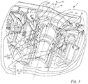
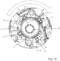
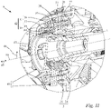
- Ein Ausführungsbeispiel der Erfindung wird im Folgenden anhand der Zeichnung erläutert. Es zeigen:
- Fig. 1
- eine perspektivische Darstellung eines geöffneten handgeführten Arbeitsgeräts mit einer Justiervorrichtung und einem Arbeitsmodul vor der Justage des Arbeitsmoduls relativ zu einer Antriebswelle des handgeführten Arbeitsgeräts,
- Fig. 2 und Fig. 3
- Schnittdarstellungen der Justiervorrichtung, des Arbeitsmoduls und der Antriebswelle des handgeführten Arbeitsgeräts aus
Fig. 1 im Justagezustand, - Fig. 4 und Fig. 5
- perspektivische Darstellungen der Justiervorrichtung aus
Fig. 1 , - Fig. 6 bis Fig. 8
- Seitenansichten auf die Justiervorrichtung aus
Fig. 1 , - Fig. 9
- eine perspektivische Darstellung eines geöffneten handgeführten Arbeitsgeräts mit der Justiervorrichtung und dem Arbeitsmodul aus
Fig. 1 , nachdem das Arbeitsmodul relativ zur Antriebswelle positioniert und fixiert worden ist und bevor die Justiervorrichtung an dem Arbeitsmodul befestigt wird, - Fig. 10
- eine Seitenansicht auf die Justiervorrichtung, bevor sie durch Drehen in den Abdeckzustand überführt wird, und
- Fig. 11
- eine Schnittdarstellung eines Schnitts durch die Justiervorrichtung, das Arbeitsmodul und die Antriebswelle des handgeführten Arbeitsgeräts aus
Fig. 9 im Abdeckzustand. -
Fig. 1 zeigt ein handgeführtes Arbeitsgerät 3. Das handgeführte Arbeitsgerät 3 ist im Ausführungsbeispiel eine Motorkettensäge. Bei dem handgeführten Arbeitsgerät kann es sich jedoch auch um einen Freischneider, um ein Blasgerät, um ein Sprühgerät oder um ein ähnliches handgeführtes Arbeitsgerät handeln. Das handgeführte Arbeitsgerät 3 ist im Ausführungsbeispiel akkubetrieben. Es kann sich jedoch auch um ein mit einem Verbrennungsmotor betriebenes handgeführtes Arbeitsgerät handeln. - Das handgeführte Arbeitsgerät 3 umfasst ein Arbeitsmodul 2. Das Arbeitsmodul 2 ist im Ausführungsbeispiel eine Ölpumpe. Die Ölpumpe fördert Öl zur Schmierung einer Sägekette der Motorkettensäge. Wie in
Fig. 2 dargestellt, ist das Arbeitsmodul 2 von einer Antriebswelle 4 des handgeführten Arbeitsgeräts 3 angetrieben. Die Antriebswelle 4 des handgeführten Arbeitsgeräts 3 dreht sich um eine Rotationsachse 50. Die Rotationsachse 50 erstreckt sich in einer Axialrichtung 49. Bei dem Arbeitsmodul 2 kann es sich auch um jede andere Art von Arbeitsmodul handeln, das von der Antriebswelle des handgeführten Arbeitsgeräts antreibbar ist. - Wie in
Fig. 1 dargestellt, umfasst das Arbeitsmodul 2 ein Getriebe 5. Das Getriebe 5 umfasst ein erstes Getriebebauteil 24 und ein zweites Getriebebauteil 25. Das erste Getriebebauteil 24 des Arbeitsmoduls 2 ist an der Antriebswelle 4 des handgeführten Arbeitsgeräts 3 angeordnet. Das erste Getriebebauteil 24 ist drehfest mit der Antriebswelle 4 verbunden. Das erste Getriebebauteil 24 ist koaxial zur Antriebswelle 4 angeordnet. Das erste Getriebebauteil 24 dreht sich im Betrieb des handgeführten Arbeitsgeräts 3 um die Rotationsachse 50. Das erste Getriebebauteil 24 ist in Axialrichtung 49 der Rotationsachse 50 gegenüber der Antriebswelle 4 unverschiebbar mit der Antriebswelle 4 verbunden. Das erste Getriebebauteil 24 weist an seiner Umfangsseite einen schraubenförmigen Gewindegang auf. Der schraubenförmige Gewindegang ist Teil einer Schneckenwelle. Das Getriebe 5 ist im Ausführungsbeispiel ein Schneckengetriebe. Das zweite Getriebebauteil 25 ist drehbar in einem Modulgehäuse 26 des Arbeitsmoduls 2 gelagert (Fig. 2 ). Das zweite Getriebebauteil 25 ist um eine Drehachse 51 drehbar. Die Drehachse 51 erstreckt sich in einer Drehachsenrichtung 52. Die Drehachsenrichtung 52 ist quer, im Ausführungsbeispiel senkrecht zu der Axialrichtung 49 der Rotationsachse orientiert. Das zweite Getriebebauteil 24 weist an seiner Umfangsseite Zähne auf. Die Zähne des zweiten Getriebebauteils 25 korrespondieren mit dem schraubenförmigen Gewindegang des ersten Getriebebauteils 24. Das zweite Getriebebauteil 25 ist ein Zahnrad. Das zweite Getriebebauteil 25 wird auch als Zahnwelle bezeichnet. Das zweite Getriebebauteil 25 ist das Schneckenrad des als Schneckengetriebe ausgebildeten Getriebes 5. - Wie in
Fig. 1 dargestellt, wird das Arbeitsmodul 2 mittels des Befestigungsmittels 28 an einem Gehäuse 27 des handgeführten Arbeitsgeräts 3 befestigt. Im Ausführungsbeispiel umfasst das Befestigungsmittel 28 zwei Schrauben und damit korrespondierende Gewinde im Gehäuse 27. Zur Befestigung des Arbeitsmoduls 2 an dem Gehäuse 27 wird das Befestigungsmittel 28 durch eine Öffnung 29 im Modulgehäuse 26 des Arbeitsmoduls 2 gesteckt. Anschließend wird das Befestigungsmittel 28 in das Gewinde des Gehäuses 27 eingeschraubt. Es ist auch jede andere Art der Befestigung denkbar. Mittels des Befestigungsmittels 28 wird das Arbeitsmodul 2 auf dem Gehäuse 27 des handgeführten Arbeitsgeräts 3 fixiert. Das Befestigungsmittel 28 drückt das Arbeitsmodul 2 gegen das Gehäuse 27 des handgeführten Arbeitsgeräts 3. Bei dieser Fixierung des Arbeitsmoduls 2 auf dem Gehäuse 27 des handgeführten Arbeitsgeräts 3 muss das Arbeitsmodul 2 relativ zur Antriebswelle 4 so positioniert sein, dass das erste Getriebebauteil 24 und das zweite Getriebebauteil 25 derart ineinandergreifen, dass das Getriebe 5 in ordnungsgemäßer, funktionstüchtiger Weise ausgebildet wird. Hierfür ist vor der Fixierung des Arbeitsmoduls 2 eine Ausrichtung des Arbeitsmoduls 2 relativ zu der Antriebswelle 4 erforderlich. - Für die Relativpositionierung von Arbeitsmodul 2 und Antriebswelle 4 ist eine Justiervorrichtung 1 vorgesehen. Die Justiervorrichtung 1 ist Bestandteil des handgeführten Arbeitsgeräts 3. Die Justiervorrichtung 1 und das Arbeitsmodul 2 bilden zusammen eine in
Fig. 2 dargestellte Moduleinheit 40. Die Justiervorrichtung 1 weist eine Modulpositioniervorrichtung 10 auf. Die Modulpositioniervorrichtung 10 dient zur Positionierung der Justiervorrichtung 1 relativ zu dem Arbeitsmodul 2. Die Modulpositioniervorrichtung 10 umfasst ein erstes Winkelpositionierelement 11 und ein zweites Winkelpositionierelement 12. Das erste Winkelpositionierelement 11 und das zweite Winkelpositionierelement 12 sind zur Winkelpositionierung der Justiervorrichtung 1 relativ zu dem Arbeitsmodul 2 bezüglich einer Verdrehung um die Rotationsachse 50 in Einsatzlage der Justiervorrichtung 1 geeignet. In Einsatzlage der Justiervorrichtung 1 liegt die Justiervorrichtung 1 auf dem Arbeitsmodul 2 auf. Die Rotationsachse 50 schneidet die Justiervorrichtung 1 in Einsatzlage der Justiervorrichtung 1. - Wie in
Fig. 6 dargestellt, sind die Winkelpositionierelemente 11 und 12 im Ausführungsbeispiel als Laschen ausgebildet. Die Justiervorrichtung 1 besitzt einen Grundkörper 22. Der Grundkörper 22 besitzt in einer Ebene senkrecht zur Rotationsachse 50 eine Außenkontur. Die Winkelpositionierelemente 11 und 12 stehen über die Außenkontur hervor. Im Ausführungsbeispiel ist die Außenkontur des Grundkörpers 22 der Justiervorrichtung 1 kreisförmig. Die Winkelpositionierelemente 11 und 12 weisen in Axialrichtung 49 durchgehende Öffnungen 58 auf. Zur Drehsicherung der Justiervorrichtung 1 relativ zum Arbeitsmodul 2 kann ein mit der Öffnung 58 korrespondierendes Bauteil des Arbeitsmoduls 2 durch die Öffnung 58 gesteckt werden. Das erste Winkelpositionierelement 11 liegt dem zweiten Winkelpositionierelement 12 bezüglich der Rotationsachse 50 in Einsatzlage der Justiervorrichtung 1 gegenüber. - Wie in
Fig. 2 dargestellt, besitzt das Arbeitsmodul 2 ein erstes Winkelpositionierteil 15 und ein zweites Winkelpositionierteil 16. Das erste Winkelpositionierteil 15 des Arbeitsmoduls 2 korrespondiert mit dem ersten Winkelpositionierelement 11 der Justiervorrichtung 1. Das zweite Winkelpositionierteil 16 des Arbeitsmoduls 2 korrespondiert mit dem zweiten Winkelpositionierelement 12 der Justiervorrichtung 1. Die Justiervorrichtung 1 weist einen Justagezustand 9 auf. Der Justagezustand 9 ist gleichzeitig auch ein Justagezustand der Moduleinheit 40. Der Justagezustand 9 ist ebenfalls ein Justagezustand des handgeführten Arbeitsgeräts 3. Im Justagezustand 9 ist das erste Winkelpositionierteil 15 des Arbeitsmoduls 2 in dem ersten Winkelpositionierelement 11 der Justiervorrichtung 1 angeordnet. Das erste Winkelpositionierteil 15 ist in das erste Winkelpositionierelement 11 gesteckt. Im Justagezustand 9 ist das zweite Winkelpositionierteil 16 des Arbeitsmoduls 2 in dem zweiten Winkelpositionierelement 12 der Justiervorrichtung 1 angeordnet. Das zweite Winkelpositionierteil 16 ist in das zweite Winkelpositionierelement 12 gesteckt. Dadurch ist die Justiervorrichtung 1 gegen ein Verdrehen um die Rotationsachse 50 gegenüber dem Arbeitsmodul 2 gesichert. Das Winkelpositionierteil 15, 16 des Arbeitsmoduls 2 steht in Axialrichtung 49 in Richtung auf die Justiervorrichtung 1 gegenüber einem Basiskörper 53 des Arbeitsmoduls 2 vor. Es kann vorgesehen sein, dass das erste Winkelpositionierelement 11 und das zweite Winkelpositionierelement 12 bezüglich der Rotationsachse 50 asymmetrisch am Grundkörper 22 der Justiervorrichtung 1 angeordnet sind. Das erste Winkelpositionierelement 11 und das zweite Winkelpositionierelement 12 und die Rotationsachse 50 liegen dann nicht auf einer Geraden senkrecht zur Rotationsachse 50. Das zweite Winkelpositionierelement 12 ist nicht in derselben Ebene wie die Rotationsachse und das erste Winkelpositionierelement 11 angeordnet. Das erste Winkelpositionierteil 15 und das zweite Winkelpositionierteil 16 sind dann korrespondierend zu dem ersten Winkelpositionierelement 11 und dem zweiten Winkelpositionierelement 12 am Arbeitsmodul 2 angeordnet. Dadurch ist die Anordnung der Justiervorrichtung 1 auf dem Arbeitsmodul 2 im Justagezustand 9 eindeutig vorgegeben. - Das Arbeitsmodul 2 umfasst eine Modulpositioniereinheit 14. Die Moduleinheit 40 besitzt ein Modulpositioniermittel 41. Das Modulpositioniermittel 41 dient zur Positionierung der Justiervorrichtung 1 relativ zu dem Arbeitsmodul 2. Das Modulpositioniermittel 41 umfasst die Modulpositioniervorrichtung 10 an der Justiervorrichtung 1 und die Modulpositioniereinheit 14 an dem Arbeitsmodul 2.
- Das erste Winkelpositionierteil 15 des Arbeitsmoduls 2 und das zweite Winkelpositionierteil 16 des Arbeitsmoduls 2 sind Bestandteil der Modulpositioniereinheit 14 des Arbeitsmoduls 2. Durch das Zusammenspiel der Modulpositioniervorrichtung 10 der Justiervorrichtung 1 und der Modulpositioniereinheit 14 des Arbeitsmoduls 4 wird die Justiervorrichtung 1 nicht nur bezüglich einer Verdrehung von Arbeitsmodul 2 und Justiervorrichtung 1 bezüglich der Rotationsachse 50 gesichert, sondern auch eine Justage der Relativposition von Justiervorrichtung 1 und Arbeitsmodul 2 bezüglich einer Radialrichtung 48 erreicht. Die Radialrichtung 48 verläuft radial zu der Rotationsachse 50. Die Radialrichtung 48 ist senkrecht zu der Rotationsachse 50 orientiert.
- Die Modulpositioniervorrichtung 10 weist ein in
Fig. 2 dargestelltes Radialpositionierelement 19 auf. Das Radialpositionierelement 19 ist zur Positionierung der Justiervorrichtung 1 relativ zu dem Arbeitsmodul 2 in Einsatzlage der Justiervorrichtung 1 bezüglich der Radialrichtung 48 geeignet. Wie inFig. 4 dargestellt, weist der Grundkörper 22 der Justiervorrichtung 1 eine äußere Umfangsseite 23 auf. Die äußere Umfangsseite 23 entspricht im Ausführungsbeispiel der Außenfläche eines Zylinders. Das Radialpositionierelement 19 ist durch einen Teile der äußeren Umfangsseite 23 des Grundkörpers 22 gebildet, wie auch in denFiguren 2 und3 dargestellt. Das Radialpositionierelement 19 läuft geschlossen um die Rotationsachse 50 um. Das Radialpositionierelement 19 ist im Ausführungsbeispiel kreisförmig. Das Radialpositionierelement 19 liegt im Justagezustand 9 an dem Arbeitsmodul 2 an. - Die Modulpositioniereinheit 14 des Arbeitsmoduls 2 umfasst ein Radialpositionierteil 54. Das Radialpositionierteil 54 korrespondiert mit dem Radialpositionierelement 19. Im Ausführungsbeispiel ist das Radialpositionierteil 54 an einem Innenumfang 55 des Modulgehäuses 27 ausgebildet. Der Innenumfang 55 weist im Ausführungsbeispiel die Form der Innenseite eines Hohlzylinders auf. Das Radialpositionierteil 54 läuft geschlossen um die Rotationsachse 50 um. Im Ausführungsbeispiel läuft das Radialpositionierteil 54 kreisförmig um die Rotationsachse 50 um. Das Radialpositionierteil 54 des Arbeitsmoduls 2 ist ein Radialanschlag für das Radialpositionierelement 19 der Justiervorrichtung 1. Im Justagezustand 9 liegt das Radialpositionierelement 19 an dem Radialpositionierteil 54 an. Dadurch ist die Relativpositionierung von Arbeitsmodul 2 und Justiervorrichtung bezüglich der Radialrichtung 48 definiert. Zur Positionierung der Justiervorrichtung 1 relativ zu dem Arbeitsmodul 2 bezüglich der Radialrichtung 48 wirken das Radialpositionierelement 19 und das Radialpositionierteil 54 zusammen.
- Durch das Zusammenspiel der Modulpositioniervorrichtung 10 der Justiervorrichtung 1 und der Modulpositioniereinheit 14 des Arbeitsmoduls 4 wird die Justiervorrichtung 1 nicht nur bezüglich einer Verdrehung von Arbeitsmodul 2 und Justiervorrichtung 1 bezüglich der Rotationsachse 50 und bezüglich einer Verschiebung von Arbeitsmodul 2 und Justiervorrichtung 1 gegeneinander bezüglich der Radialrichtung 48 gesichert, sondern auch eine Justage der Relativposition von Justiervorrichtung 1 und Arbeitsmodul 2 bezüglich der Axialrichtung 49 erreicht.
- Die Modulpositioniervorrichtung 10 weist ein in den
Figuren 3 und4 dargestelltes erstes Axialpositionierelement 13 auf. Das erste Axialpositionierelement 13 ist zur Positionierung der Justiervorrichtung 1 relativ zu dem Arbeitsmodul 2 in Einsatzlage der Justiervorrichtung 1 bezüglich der Axialrichtung 49 der Rotationsachse 50 geeignet. An der inFig. 4 dargestellten äußeren Umfangsseite 23 des Grundkörpers 22 ist ein Steg 32 angeordnet. Der Steg 32 steht in Radialrichtung 48 über den Grundkörper 22 hervor. Der Steg 32 steht in Radialrichtung 48 über die äußere Umfangsseite 23 des Grundkörpers 22 hervor. Der Steg 32 ist in Axialrichtung 49 durch das erste Axialpositionierelement 13 begrenzt. Das erste Axialpositionierelement 13 ist Bestandteil des Stegs 32. Das erste Axialpositionierelement 13 ist die Stirnseite des Stegs 32. Das erste Axialpositionierelement steht in Radialrichtung 48 über den Grundkörper 22 hervor. Das erste Axialpositionierelement 13 ist im inFig. 3 dargestellten Justagezustand 9 dem Arbeitsmodul 2 zugewandt. Das erste Axialpositionierelement 13 liegt im Justagezustand 9 an dem Arbeitsmodul 2 an. - Wie in
Fig. 4 dargestellt, weist die Justiervorrichtung 1 insgesamt zwei erste Axialpositionierelemente 13 auf. In Einsatzlage der Justiervorrichtung 1 liegen sich die beiden ersten Axialpositionierelemente 13 bezüglich der Rotationsachse 50 gegenüber. In Einsatzlage der Justiervorrichtung 1 liegen sich die beiden ersten Axialpositionierelemente 13 an der äußeren Umfangsseite 23 des Grundkörpers 22 diametral gegenüber. Ansonsten ist das weitere erste Axialpositionierelement 13 analog zum bereits beschriebenen ersten Axialpositionierelement 13 ausgebildet. - Die Justiervorrichtung 1 weist ein zweites Axialpositionierelement 18 auf. Das zweite Axialpositionierelement 18 dient ebenfalls zur Relativpositionierung der Justiervorrichtung 1 und des Arbeitsmoduls 2 in Einsatzlage der Justiervorrichtung 1 bezüglich der Axialrichtung 49 der Rotationsachse 50. Im Ausführungsbeispiel ist das zweite Axialpositionierelement 18 an dem ersten Winkelpositionierelement 11 bzw. an dem zweiten Winkelpositionierelement 12 ausgebildet. Das zweite Axialpositionierelement 18 steht in Radialrichtung 48 über den Grundkörper 22 der Justiervorrichtung 1 hervor. Das zweite Axialpositionierelement 18 steht über die äußere Umfangsseite 23 in Radialrichtung 48 hervor. Das zweite Axialpositionierelement 18 ist durch die Stirnseite des Winkelpositionierelements 11 bzw. 12 gebildet. Das zweite Axialpositionierelement 18 ist im Justagezustand 9 dem Arbeitsmodul 2 zugewandt. Im Justagezustand 9 liegt die Justiervorrichtung 1 mit dem zweiten Axialpositionierelement 18 an dem Arbeitsmodul 2 an.
- Im Ausführungsbeispiel sind zwei zweite Axialpositionierelemente 18 vorgesehen. Die beiden zweiten Axialpositionierelemente 18 liegen sich bezüglich der Rotationsachse 50 gegenüber. In Einsatzlage der Justiervorrichtung 1 liegen sich die beiden zweiten Axialpositionierelemente 18 an der äußeren Umfangsseite 23 des Grundkörpers 22 diametral gegenüber. In Umfangsrichtung 47 bezüglich der Rotationsachse 50 sind an der äußeren Umfangsseite 23 des Grundkörpers 22 der Justiervorrichtung 1 abwechselnd erste Axialpositionierelemente 13 und zweite Axialpositionierelemente 18 angeordnet. Bezüglich der Rotationsachse 50 ist das zweite Axialpositionierelement 18 in einem Winkelabstand von 80° bis 100°, insbesondere von 90° zu dem ersten Axialpositionierelement 13 angeordnet. Im Ausführungsbeispiel sind die ersten Axialpositionierelemente 13 und die zweiten Axialpositionierelemente 18 in gleich großen Winkelabständen zueinander angeordnet.
- Das erste Axialpositionierelement 13 und das zweite Axialpositionierelement 18 sind bezüglich der Axialrichtung 49 auf gleicher Höhe angeordnet. Das erste Axialpositionierelement 13 und das zweite Axialpositionierelement 18 bilden gemeinsam eine Anlagefläche der Justiervorrichtung 1 zur Anlage an dem Arbeitsmodul 2.
- Wie in
Fig. 3 dargestellt, ist das erste Axialpositionierelement 13 Bestandteil der Modulpositioniervorrichtung 10. Auch das zweite Axialpositionierelement 18 ist Bestandteil der Modulpositioniervorrichtung 10. Die Modulpositioniervorrichtung 10 umfasst das erste Winkelpositionierelement 11, das zweite Winkelpositionierelement 12, das Radialpositionierelement 19, die beiden ersten Axialpositionierelemente 13 und die beiden zweiten Axialpositionierelemente 18 (Figuren 3 und4 ). - Die Modulpositioniereinheit 14 des Arbeitsmoduls 2 umfasst einen Modulanschlag 17. Der Modulanschlag 17 korrespondiert mit dem ersten Axialpositionierelement 13. Im Ausführungsbeispiel korrespondiert der Modulanschlag 17 auch mit dem zweiten Axialpositionierelement 18. Im Ausführungsbeispiel ist der Modulanschlag 17 eine um die Rotationsachse 50 umlaufende Kante des Arbeitsmoduls 2. Im Ausführungsbeispiel läuft der Modulanschlag 17 kreisförmig um die Rotationsachse 50 um. Im Ausführungsbeispiel läuft der Modulanschlag 17 geschlossen um die Rotationsachse 50 um.
- Im Justagezustand 9 liegen das erste Axialpositionierelement 13 und das zweite Axialpositionierelement 18 an dem Modulanschlag 17 an. Dadurch ist die Relativpositionierung von Arbeitsmodul 2 und Justiervorrichtung 1 bezüglich der Axialrichtung 49 der Rotationsachse 50 definiert. Zur Positionierung der Justiervorrichtung 1 relativ zu dem Arbeitsmodul 2 bezüglich der Axialrichtung 49 der Rotationsachse 50 wirken das Axialpositionierelement 13, 18 und der Modulanschlag 17 zusammen.
- Wie die Zusammenschau der
Figuren 2 und3 zeigt, umfasst die Modulpositioniereinheit 14 das erste Winkelpositionierelement 15, das zweite Winkelpositionierelement 16, den Modulanschlag 17 und das Radialpositionierteil 54. - Die Justiervorrichtung 1 weist eine in den
Fig. 3 und4 dargestellte Wellenpositioniervorrichtung 20 auf. Die Wellenpositioniervorrichtung 20 dient zur Positionierung der Justiervorrichtung 1 relativ zu der Antriebswelle 4. Die Wellenpositioniervorrichtung 20 steht in Axialrichtung 49 über den Grundkörper 22 der Justiervorrichtung 1 vor. Im Justagezustand 9 ist die Wellenpositioniervorrichtung 20 dem Arbeitsmodul 2 zugewandt. - Wie in
Fig. 3 dargestellt, ist an der Antriebswelle 4 eine Wellenpositioniereinheit 21 angeordnet. Die Wellenpositioniervorrichtung 20 und die Wellenpositioniereinheit 21 bilden gemeinsam ein Wellenpositioniermittel 43. Das Wellenpositioniermittel 43 dient zur Positionierung der Justiervorrichtung 1 relativ zu der Antriebswelle 4. Das Wellenpositioniermittel 43 umfasst die Wellenpositioniervorrichtung 20 der Justiervorrichtung 1 und die Wellenpositioniereinheit 21 an der Antriebswelle 4. - Wie in
Fig. 3 dargestellt, weist die Antriebswelle 4 ein offenes Ende 33 auf. Das offene Ende 33 ist am Längsende der Antriebswelle 4 angeordnet. Die Antriebswelle 4 ist am offenen Ende 33 hohl ausgebildet. Die Antriebswelle 4 weist am offenen Ende 33 die Form eines Hohlzylinders auf. - Die Wellenpositioniereinheit 21 ist im Ausführungsbeispiel Bestandteil des Arbeitsmoduls 2. Die Wellenpositioniereinheit 21 ist an dem offenen Ende 33 der Antriebswelle 4 angeordnet. Die Wellenpositioniereinheit 21 ist in das offene Ende 33 der Antriebswelle 4 gesteckt. Die Wellenpositioniereinheit 21 ist drehfest mit der Antriebswelle 4 verbunden. Im Ausführungsbeispiel ist die Wellenpositioniereinheit 21 Bestandteil des ersten Getriebebauteils 24 des Arbeitsmoduls 2.
- Das erste Getriebebauteil 24 des Arbeitsmoduls 2 greift in die Antriebswelle 4 des handgeführten Arbeitsgeräts 3 ein. Das erste Getriebebauteil 24 ist in das offene Ende 33 der Antriebswelle 4 gesteckt. Das erste Getriebebauteil 24 ist drehfest mit der Antriebswelle 4 verbunden. Das erste Getriebebauteil 24 besitzt eine Endöffnung 34. Die Endöffnung 34 ist an einem der Antriebswelle 4 abgewandten Längsende des ersten Getriebebauteils 24 ausgebildet. Die Endöffnung 34 öffnet in Axialrichtung 49. Die Rotationsachse 50 verläuft durch die Endöffnung 34. Im Ausführungsbeispiel ist die Endöffnung 34 des ersten Getriebebauteils 24 Bestandteil der Wellenpositioniereinheit 21.
- Zur Relativpositionierung von Justiervorrichtung 1 und Antriebswelle 4 wirken die Wellenpositioniervorrichtung 20 und die Wellenpositioniereinheit 21 zusammen. Zur Relativpositionierung der Justiervorrichtung 1 und der Antriebswelle 4 wirken die Wellenpositioniervorrichtung 20 der Justiervorrichtung 1 und das erste Getriebebauteil 24 zusammen. Die Wellenpositioniervorrichtung 20 wird in die Endöffnung 34 des ersten Getriebebauteils 24 gesteckt. Die Wellenpositioniervorrichtung 20 der Justiervorrichtung 1 und die Wellenpositioniereinheit 21 an der Antriebswelle 4 korrespondieren miteinander. Die Endöffnung 34 und die Wellenpositioniervorrichtung 20 korrespondieren miteinander.
- Wie insbesondere in
Fig. 6 dargestellt, weist die Wellenpositioniervorrichtung 20 eine im Wesentlichen zylindrische Außenkontur auf. In einer Ebene senkrecht zur Rotationsachse 50 ist die Außenkontur der Wellenpositioniervorrichtung 20 im Wesentlichen kreisförmig. In Axialrichtung 49 weist die ansonsten zylindrische Wellenpositioniervorrichtung 20 Schlitze 39 auf. Aufgrund der Schlitze 39 ist die Wellenpositioniervorrichtung 20 nicht vollständig starr. Die Wellenpositioniervorrichtung 20 kann in die Endöffnung 34 des ersten Getriebebauteils 24 gedrückt werden. Im Justagezustand 9 drückt die Wellenpositioniervorrichtung 20 in Radialrichtung 48 nach außen gegen das erste Getriebebauteil 24. Auf diese Weise ist die Justiervorrichtung 1 geklemmt in dem ersten Getriebebauteil 24 gehalten. - Wie in
Fig. 2 oder auch inFig. 6 dargestellt, verläuft die Rotationsachse 50 zentral durch die im Wesentlichen kreisförmige Außenkontur der Wellenpositioniervorrichtung 20. Die Wellenpositioniervorrichtung 20 ist exzentrisch zu der kreisförmigen äußeren Umfangsseite 23 des Grundkörpers 22 der Justiervorrichtung 1 angeordnet. Die Wellenpositioniervorrichtung 20 weist einen radial zur Rotationsachse 50 gemessenen maximalen Abstand dmax zu einer inneren Umfangsseite 35 des Grundkörpers 22 der Justiervorrichtung 1 auf. Die Wellenpositioniervorrichtung 20 weist einen radial zur Rotationsachse 50 gemessenen minimalen Abstand dmin zu der inneren Umfangsseite 35 des Grundkörpers 22 der Justiervorrichtung 1 auf. Wie inFig. 2 dargestellt, ist im Justagezustand 9 im Bereich des maximalen Abstands dmax das zweite Getriebebauteil 25 angeordnet. Der Bereich des maximalen Abstands dmax der Justiervorrichtung 1 ist oberhalb des zweiten Getriebebauteils 25 angeordnet. Im Justagezustand 9 ist das zweite Getriebebauteil 25 im Modulgehäuse 26 unterhalb des Bereichs des maximalen Abstands dmax der Justiervorrichtung 1 gelagert. Im Justagezustand 9 ist das Arbeitsmodul 2 mittels der Justiervorrichtung 1 relativ zur Antriebswelle 4 so ausgerichtet, dass das erste Getriebebauteil 24 und das zweite Getriebebauteil 25 zur Ausbildung des Getriebes 5 ineinandergreifen. - Im Justagezustand 9 ist die Justiervorrichtung 1 drehfest mit dem Arbeitsmodul 2 verbunden. Die Justiervorrichtung 1 und das Arbeitsmodul 2 bilden die Moduleinheit 40. Durch das Wellenpositioniermittel 43 ist die Justiervorrichtung 1 relativ zu der Antriebswelle 4 ausgerichtet. Durch das Modulpositioniermittel 41 ist das Arbeitsmodul 2 relativ zu der Justiervorrichtung 1 ausgerichtet. Dadurch ist die Antriebswelle 4 relativ zu dem Arbeitsmodul 2 ausgerichtet. Das drehfest mit der Antriebswelle 4 verbundene erste Getriebebauteil 24 ist relativ zu dem im Modulgehäuse 26 des Arbeitsmoduls 2 gelagerten zweiten Getriebebauteil 25 ausgerichtet. Im Justagezustand 9 lässt sich die Justiervorrichtung 1 gemeinsam mit dem Arbeitsmodul 2 um die Rotationsachse 50 verschwenken. Die Justiervorrichtung 1, das Arbeitsmodul 2 und die Antriebswelle 4 sind so ausgelegt, dass das zweite Getriebebauteil 25 im Justagezustand 9 in einem Schwenkbereich um die Rotationsachse 50 verschwenkbar ist. Die Justiervorrichtung 1, das Arbeitsmodul 2 und die Antriebselle 4 sind so ausgelegt, dass das zweite Getriebebauteil 25 im Justagezustand 9 in einem Schwenkbereich um das erste Getriebebauteil 24 verschwenkbar ist. Das erste Getriebebauteil 24 und das zweite Getriebebauteil 25 greifen zur Ausbildung des Getriebes 5 in jeder Schwenkstellung des Schwenkbereichs ineinander. Der in den Fig. nicht dargestellte Schwenkbereich beträgt bezüglich einer Fixierstellung des Arbeitsmoduls 2 auf dem Gehäuse 27 des handgeführten Arbeitsgeräts 3 ± 5°, insbesondere ± 10°, bevorzugt ± 20°. Aufgrund der Verschwenkbarkeit des zweiten Getriebebauteils 25 um das erste Getriebebauteil 24 ist das Modulgehäuse 26 in die Fixierstellung schwenkbar und in der Fixierstellung an dem Gehäuse 27 des handgeführten Arbeitsgeräts 3 fixierbar. In der Fixierstellung kann das Befestigungsmittel 28 durch die in
Fig. 1 dargestellte Öffnung 29 im Modulgehäuse 26 des Arbeitsmoduls 2 in das zugehörige Gewinde im Gehäuse 27 des handgeführten Arbeitsgeräts 3 geschraubt werden. Gleichzeitig ist gewährleistet, dass in jeder Schwenkstellung das Getriebe 5 funktioniert. Bei dem funktionierenden Getriebe 5 greifen die Zähne des zweiten Getriebebauteils 25 in den schraubenförmigen Gewindegang des ersten Getriebebauteils 24. Das zweite Getriebebauteil 25 wird von dem ersten Getriebebauteil 24 angetrieben. - Die Justiervorrichtung 1 wird zur Montage des Arbeitsmoduls 2 auf dem Gehäuse 27 des handgeführten Arbeitsgeräts 3 im Justagezustand 9 auf das Arbeitsmodul 2 aufgebracht. Das Arbeitsmodul 2 ist über die Wellenpositioniereinheit 21 des Arbeitsmoduls 2 mit der Antriebswelle 4 des handgeführten Arbeitsgeräts 3 verbunden. Die Positionierung oder Justage des Arbeitsmoduls 2 auf dem Gehäuse 27 erfolgt durch Verschwenken des Arbeitsmoduls 2 in die Fixierstellung. Nach der Fixierung des Arbeitsmoduls 2 an dem Gehäuse 27 kann die Justiervorrichtung 1 aus dem Justagezustand 9 entfernt werden.
- Wie in den
Figuren 9 bis 11 dargestellt, ist die Justiervorrichtung 1 so ausgebildet, dass die Justiervorrichtung 1 zur Abdeckung des Arbeitsmoduls 2 geeignet ist. Wie inFig. 11 dargestellt, ist die Justiervorrichtung 1 insbesondere zur Abdeckung des Getriebes 5 geeignet. Die Justiervorrichtung 1 lässt sich so auf dem Modulgehäuse 26 des Arbeitsmoduls 2 anordnen, dass das Getriebe 5 vollständig abgedeckt ist. Das Getriebe 5 ist in der Moduleinheit 40 bestehend aus Justiervorrichtung 1 und Arbeitsmodul 2 eingeschlossen. Das Getriebe 5 ist von der Justiervorrichtung 1 und dem Modulgehäuse 26 umschlossen. Die Öffnung im Modulgehäuse 26 für die Antriebswelle 4 ist durch die Antriebswelle 4 und das erste Getriebebauteil 24 ausgefüllt und abgedeckt. - Die Justiervorrichtung 1 ist so ausgelegt, dass sie zur Befestigung an dem Arbeitsmodul 2 geeignet ist. Wie insbesondere in
Fig. 11 dargestellt, umfasst die Justiervorrichtung 1 ein Sicherungselement 30. Das Sicherungselement 30 dient zur Halterung der Justiervorrichtung 1 an dem Arbeitsmodul 2. Die Justiervorrichtung 1 ist so ausgelegt, dass sie mittels des Sicherungselements 30 an dem Arbeitsmodul 2 drehsicher bezüglich der Rotationsachse 50 und abziehsicher bezüglich der Axialrichtung 49 sicherbar ist. - Wie in
Fig. 4 dargestellt, weist die Justiervorrichtung 1 eine Justierseite 6 auf. Wie inFig. 5 dargestellt, weist die Justiervorrichtung 1 eine Abdeckseite 7 auf. Die Justierseite 6 und die Abdeckseite 7 weisen in entgegengesetzte Richtungen. Dies ist insbesondere inFig. 8 dargestellt. - Die
Figuren 2 und3 zeigen den Justagezustand 9 des handgeführten Arbeitsgeräts 3 bzw. der Justiervorrichtung 1. Im Justagezustand 9 ist die Justierseite 6 der Justiervorrichtung 1 dem Arbeitsmodul 2 zugewandt. Im Justagezustand 9 ist das Arbeitsmodul 2 mittels der Justiervorrichtung 1 relativ zu der Antriebswelle 4 positionierbar. Die Justiervorrichtung 1 ist so ausgelegt, dass im Justagezustand 9 das Arbeitsmodul 2 mittels der Justiervorrichtung 1 relativ zu der Antriebswelle 4 positionierbar ist, wobei die Justierseite 6 dem Arbeitsmodul 2 zugewandt ist. -
Fig. 11 zeigt einen Abdeckzustand 8 des handgeführten Arbeitsgeräts 3. Der Abdeckzustand 8 ist auch der Abdeckzustand der Justiervorrichtung 1. Der Abdeckzustand 8 ist ebenso der Abdeckzustand der Moduleinheit 40 aus Justiervorrichtung 1 und Arbeitsmodul 2. Im Abdeckzustand 8 ist das Arbeitsmodul 2 mit der Abdeckseite 7 der Justiervorrichtung 1 abdeckbar. Im Abdeckzustand 8 ist die Abdeckseite 7 der Justiervorrichtung 1 dem Arbeitsmodul 2 zugewandt. Die Justiervorrichtung 1 ist so ausgelegt, dass das Arbeitsmodul 2 in dem Abdeckzustand 8 mit der Abdeckseite 7 abdeckbar ist. - Auf der Justierseite 6 der Justiervorrichtung 1 ist die Wellenpositioniervorrichtung 20 angeordnet. Im Justagezustand 9 des handgeführten Arbeitsgeräts 3 ist die Justierseite 6 der Justiervorrichtung 1 der Antriebswelle 4 zugewandt. Im Abdeckzustand 8 des handgeführten Arbeitsgeräts 3 ist die Abdeckseite 7 der Justiervorrichtung 1 der Antriebswelle 4 zugewandt.
- Wie in
Fig. 11 dargestellt, umfasst die Moduleinheit 40 ein Sicherungsmittel 42. Das Sicherungsmittel 42 umfasst das Sicherungselement 30 der Justiervorrichtung 1 und ein Sicherungsteil 31 des Arbeitsmoduls 2. Im Abdeckzustand 8 wirkt zur Sicherung gegen eine Relativbewegung von Justiervorrichtung 1 und Arbeitsmodul 2 in Axialrichtung 49 das Sicherungselement 30 mit dem Sicherungsteil 31 zusammen. Im Abdeckzustand 8 wirkt zur Sicherung gegen eine Drehbewegung der Justiervorrichtung 1 gegenüber dem Arbeitsmodul 2 bezüglich der Rotationsachse 50 das Sicherungselement 30 mit dem Sicherungsteil 31 zusammen. Im Abdeckzustand 8 wirkt zur Sicherung gegen eine Verschiebung der Justiervorrichtung 1 gegenüber dem Arbeitsmodul 2 bezüglich der Radialrichtung 48 das Sicherungselement 30 mit dem Sicherungsteil 31 zusammen. - Im Abdeckzustand 8 ist die Justiervorrichtung 1 am Arbeitsmodul 2 gehalten. Im Abdeckzustand 8 ist ein Betrieb des handgeführten Arbeitsgeräts 3 ohne ein Verlieren der Justiervorrichtung 1 möglich. Wird die Justiervorrichtung 1 für einen Austausch des Arbeitsmoduls 2 oder ein Nachjustieren des Arbeitsmoduls 2 auf dem Gehäuse 27 des handgeführten Arbeitsgeräts 3 benötigt, ist die Justiervorrichtung 1 griffbereit im Abdeckzustand 8 verfügbar.
- Im Abdeckzustand 8 ist die Justiervorrichtung 1 mittels des Sicherungsmittels 42 an dem Arbeitsmodul 2 gehalten. Im Abdeckzustand 8 deckt die Justiervorrichtung 1 das Getriebe 5 des Arbeitsmoduls 2 ab.
- In Einsatzlage der Justiervorrichtung 1 befindet sich die Justiervorrichtung 1 im Abdeckzustand 8 oder im Justagezustand 9.
- Wie in
Fig. 5 dargestellt, besitzt der Grundkörper 22 der Justiervorrichtung 1 eine Mittelplatte 36. Die innere Umfangsseite 35 des Grundkörpers 2 läuft geschlossen um die Mittelplatte 36 um. Als Teil der Abdeckseite 7 der Justiervorrichtung 1 bildet die Mittelplatte 36 einen Boden der Justiervorrichtung 1. Als Teil der inFig. 4 dargestellten Justierseite 6 der Justiervorrichtung 1 bildet die Mittelplatte 36 einen Träger für die Wellenpositioniervorrichtung 20. Auf der Abdeckseite 7 ist die Mittelplatte 36 frei von Bauelementen. Auf der Abdeckseite 7 ist die Justiervorrichtung 1 im Bereich der Mittelplatte 36 eben ausgebildet. Auf der Abdeckseite 7 der Justiervorrichtung 1 ist die Justiervorrichtung 1 im Bereich der Mittelplatte frei von Bauteilen, die in Axialrichtung 49 über die Mittelplatte 36 hervorstehen. Wie inFig. 11 dargestellt, ist die Antriebswelle 4 im Abdeckzustand 8 ungestört von der Justiervorrichtung 1. Das an der Antriebswelle 4 angeordnete erste Getriebebauteil 24 ist im Abdeckzustand 8 ungestört von der Justiervorrichtung 1. Eine Rotation der Antriebswelle 4 ist im Abdeckzustand 8 ungestört von der Justiervorrichtung 1 möglich. - Wie in den
Figuren 5 und7 dargestellt, weist die Justiervorrichtung 1 einen um die Rotationsachse 50 umlaufenden Flansch 37 auf. Der Flansch 37 steht in Radialrichtung 48 über den Grundkörper 22 der Justiervorrichtung 1 vor. Der Flansch 37 steht über die äußere Umfangsseite 23 des Grundkörpers 22 in Radialrichtung 48 vor. Wie inFig. 11 dargestellt, liegt der Flansch 37 im Abdeckzustand 8 an einem Vorsprung 38 des Modulgehäuses 26 des Arbeitsmoduls 2 an. Der Vorsprung 38 des Modulgehäuses 26 läuft geschlossen um die Rotationsachse 50 um. Der Vorsprung 38 des Modulgehäuses 26 korrespondiert mit dem Flansch 37 der Justiervorrichtung 1. Im Ausführungsbeispiel ist der Vorsprung 38 in Axialrichtung 49 kreisförmig. Durch das Zusammenspiel des Flansches 37 der Justiervorrichtung 1 und des Vorsprungs 38 des Arbeitsmoduls 2 ist das Arbeitsmodul 2 durch die Justiervorrichtung 1 vollständig abgedeckt. - Wie in
Fig. 7 dargestellt, umfasst das Sicherungselement 30 eine Axialsicherung 44 und eine Drehsicherung 45. Die Axialsicherung 44 ist durch einen Fortsatz in Radialrichtung 48 an dem Flansch 37 ausgebildet. Die Drehsicherung 45 ist durch einen Kragarm ausgebildet. Der Kragarm ist so ausgebildet, dass er in Umfangsrichtung 47 einen Hinterschnitt bildet. Der Hinterschnitt bildet die Drehsicherung 45. Zwischen der als Kragarm ausgebildeten Drehsicherung 45 und dem umlaufenden Flansch 37 ist ein Spalt 46 ausgebildet. Der Kragarm ist an dem Flansch 37 festgelegt. Das Sicherungsteil 31 umfasst einen Stift 57. Durch den Spalt 46 ist der Kragarm so flexibel, dass der inFig. 11 dargestellte Stift 57 in den Hinterschnitt des Kragarms eingeführt werden kann. Die Justiervorrichtung 1 befindet sich dann im Abdeckzustand 8. Im Abdeckzustand 8 ist die Justiervorrichtung 1 gegen ein Verdrehen gegenüber dem Arbeitsmodul 2 zumindest bis zu einem Grenzdrehmoment gesichert. Der gegenüber dem Basiskörper 53 des Arbeitsmoduls 2 in Axialrichtung 49 in Richtung auf die Justiervorrichtung 1 vorstehende Stift 57 liegt in Umfangsrichtung 47 an der als Hinterschnitt des Kragarms ausgebildeten Drehsicherung 45 an. Bei Überschreiten des Grenzdrehmoments kann die Justiervorrichtung 1 gegenüber dem Arbeitsmodul 2 gedreht werden und von dem Arbeitsmodul 2 gelöst werden. - Das Sicherungsteil 31 weist eine Aussparung 56 auf. Die Aussparung 56 ist ein in Radialrichtung 48 in den Stift 57 eingebrachter Schlitz. Die Aussparung 56 bildet bezüglich der Axialrichtung 49 einen Hinterschnitt in dem Stift 57. Im Abdeckzustand 8 greift die Axialsicherung 44 in die Aussparung 56 ein. Die Justiervorrichtung 1 ist gegen eine Bewegung relativ zu dem Arbeitsmodul 2 in Axialrichtung 49 gesichert.
- Wie in
Fig. 7 dargestellt, ist die Axialsicherung 44 der Justiervorrichtung 1 ein Fortsatz des Flansches 37. Die Axialsicherung 44 steht in Radialrichtung 48 gegenüber dem Grundkörper 22 der Justiervorrichtung 1 vor. Die Axialsicherung 44 steht in Radialrichtung 48 gegenüber dem Flansch 37 vor. - Wie in
Fig. 10 dargestellt, umfasst das Sicherungsteil 31 zwei Stifte 57. Die beiden Stifte 57 sind bezüglich der Rotationsachse 50 gegenüberliegend zueinander angeordnet (Fig. 2 ). Im Abdeckzustand 8 ist die Justiervorrichtung 1 bezüglich der Radialrichtung 48 zwischen den beiden Stiften 57 angeordnet, wie die Zusammenschau derFiguren 10 und11 zeigt. Die Stifte 57 bilden eine Radialsicherung für die Justiervorrichtung 1. Durch das Zusammenspiel des Grundkörpers 22 bzw. der mit dem Grundkörper 22 verbundenen Axialsicherungen 44 mit den Stifte 57 ist im Abdeckzustand 8 eine Bewegung der Justiervorrichtung 1 in eine ausgezeichnete erste Radialrichtung unterbunden. Durch das Zusammenspiel der Drehsicherungen 45 und der Stifte 57 ist im Abdeckzustand 8 eine Bewegung der Justiervorrichtung 1 in eine ausgezeichnete zweite Radialrichtung unterbunden. Die ausgezeichnete erste Radialrichtung verläuft quer, im Ausführungsbeispiel senkrecht zu der ausgezeichneten zweiten Radialrichtung. - Wie sich aus den
Figuren 2 und11 ergibt, ist das erste Winkelpositionierelement 15 durch einen der beiden Stifte 57 und das zweite Winkelpositionierelement 16 durch den anderen der beiden Stifte 57 gebildet. Die Stifte 57 sind sowohl Bestandteil des Sicherungsteils 31 als auch der Modulpositioniereinheit 14. Die Stifte 57 sind sowohl zur Sicherung der Justiervorrichtung auf dem Arbeitsmodul 2 als auch zur Relativpositionierung von Arbeitsmodul 2 und Justiervorrichtung 1 nutzbar. Das Sicherungsteil 31 des Arbeitsmoduls 2 ist Bestandteil der Modulpositioniereinheit 14. Das Sicherungsteil 31 ist sowohl zur Sicherung der Justiervorrichtung 1 auf dem Arbeitsmodul 2 als auch zur Relativpositionierung von Arbeitsmodul 2 und Justiervorrichtung 1 nutzbar. - Nach der Justage und Fixierung des Arbeitsmoduls 2 in der Fixierstellung wird die Justiervorrichtung 1 aus dem Justagezustand 9 entfernt und in den Abdeckzustand 8 überführt. Die Justiervorrichtung 1 ist im Abdeckzustand 8 mittels des Sicherungsmittels 42 an dem in der Fixierstellung befindlichen Arbeitsmodul 2 gehalten.
Claims (15)
- Justiervorrichtung zur Relativpositionierung eines Arbeitsmoduls (2) relativ zu einer um eine Rotationsachse (50) rotierenden Antriebswelle (4) eines handgeführten Arbeitsgeräts (3) zum Antrieb des Arbeitsmoduls (2),
dadurch gekennzeichnet, dass die Justiervorrichtung (1) eine Modulpositioniervorrichtung (10) zur Positionierung der Justiervorrichtung (1) relativ zu dem Arbeitsmodul (2) aufweist, dass die Justiervorrichtung (1) eine Wellenpositioniervorrichtung (20) zur Positionierung der Justiervorrichtung (1) relativ zu der Antriebswelle (4) aufweist, und dass die Justiervorrichtung (1) so ausgebildet ist, dass sie zur Abdeckung des Arbeitsmoduls (2), insbesondere zur Abdeckung eines Getriebes (5) des Arbeitsmoduls (2), geeignet ist. - Justiervorrichtung nach Anspruch 1,
dadurch gekennzeichnet, dass die Modulpositioniervorrichtung (10) Winkelpositionierelemente (11, 12) aufweist, und dass die Winkelpositionierelemente (11, 12) zur Winkelpositionierung der Justiervorrichtung (1) relativ zu dem Arbeitsmodul (2) bezüglich einer Verdrehung um die Rotationsachse (50) in Einsatzlage der Justiervorrichtung (1) geeignet sind. - Justiervorrichtung nach Anspruch 1 oder 2,
dadurch gekennzeichnet, dass die Modulpositioniervorrichtung (10) ein Axialpositionierelement (13) aufweist, und dass das Axialpositionierelement (13) zur Positionierung der Justiervorrichtung (1) relativ zu dem Arbeitsmodul (2) in Einsatzlage der Justiervorrichtung (1) bezüglich einer Axialrichtung (49) der Rotationsachse (50) geeignet ist. - Justiervorrichtung nach einem der Ansprüche 1 bis 3,
dadurch gekennzeichnet, dass die Justiervorrichtung (1) so ausgelegt ist, dass sie zur Befestigung an dem Arbeitsmodul (2) geeignet ist. - Justiervorrichtung nach einem der Ansprüche 1 bis 4,
dadurch gekennzeichnet, dass die Justiervorrichtung (1) eine Justierseite (6) und eine Abdeckseite (7) aufweist, und dass die Justiervorrichtung (1) so ausgelegt ist,- dass in einem Abdeckzustand (8) das Arbeitsmodul (2) mit der Abdeckseite (7) abdeckbar ist und- dass in einem Justagezustand (9) das Arbeitsmodul (2) mittels der Justiervorrichtung (1) relativ zu der Antriebswelle (4) positionierbar ist, wobei die Justierseite (6) dem Arbeitsmodul (2) zugewandt ist. - Justiervorrichtung nach einem der Ansprüche 1 bis 5,
dadurch gekennzeichnet, dass die Justiervorrichtung (1) ein Sicherungselement (30) zur Halterung an dem Arbeitsmodul (2) aufweist. - Justiervorrichtung nach den Ansprüchen 5 und 6,
dadurch gekennzeichnet, dass die Justiervorrichtung (1) so ausgelegt ist, dass sie im Abdeckzustand (8) mittels des Sicherungselements (30) an dem Arbeitsmodul (2) drehsicher bezüglich der Rotationsachse (50) und abziehsicher bezüglich der Axialrichtung (49) sicherbar ist. - Moduleinheit umfassend ein Arbeitsmodul (2) und eine Justiervorrichtung (1) nach einem der Ansprüche 1 bis 7,
dadurch gekennzeichnet, dass die Moduleinheit (40) ein Modulpositioniermittel (41) zur Positionierung der Justiervorrichtung (1) relativ zu dem Arbeitsmodul (2) aufweist, dass das Modulpositioniermittel (41) die Modulpositioniervorrichtung (10) an der Justiervorrichtung (1) und eine Modulpositioniereinheit (14) an dem Arbeitsmodul (2) umfasst. - Moduleinheit nach Anspruch 8,
dadurch gekennzeichnet, dass die Moduleinheit (40) ein Sicherungsmittel (42) aufweist, dass das Sicherungsmittel (42) ein Sicherungselement (30) der Justiervorrichtung (1) und ein Sicherungsteil (31) des Arbeitsmoduls (2) umfasst, und dass zur Sicherung gegen eine Relativbewegung von Justiervorrichtung (1) und Arbeitsmodul (2) gegeneinander in Axialrichtung (49) und zur Sicherung gegen eine Drehbewegung der Justiervorrichtung (1) gegenüber dem Arbeitsmodul (2) bezüglich der Rotationsachse (50) das Sicherungselement (30) mit dem Sicherungsteil (31) zusammenwirkt. - Moduleinheit nach Anspruch 9,
dadurch gekennzeichnet, dass das Sicherungsteil (31) des Arbeitsmoduls (2) Bestandteil der Modulpositioniereinheit (14) ist und sowohl zur Sicherung der Justiervorrichtung (1) auf dem Arbeitsmodul (2) als auch zur Relativpositionierung von Arbeitsmodul (2) und Justiervorrichtung (1) nutzbar ist. - Handgeführtes Arbeitsgerät umfassend eine Moduleinheit (40) nach einem der Ansprüche 8 bis 10 und eine Antriebswelle (4) zum Antrieb des Arbeitsmoduls (2),
dadurch gekennzeichnet, dass die Moduleinheit (40) ein Wellenpositioniermittel (43) zur Positionierung der Justiervorrichtung (1) relativ zu der Antriebswelle (4) aufweist, dass das Wellenpositioniermittel (43) die Wellenpositioniervorrichtung (20) der Justiervorrichtung (1) und eine Wellenpositioniereinheit (21) an der Antriebswelle (4) umfasst. - Handgeführtes Arbeitsgerät nach Anspruch 11,
dadurch gekennzeichnet, dass die Justiervorrichtung (1) eine Justierseite (6) und eine Abdeckseite (7) aufweist, dass auf der Justierseite (6) die Wellenpositioniervorrichtung (20) angeordnet ist,- dass in einem Justagezustand (9) des handgeführten Arbeitsgeräts (3) die Justierseite (6) der Justiervorrichtung (1) der Antriebswelle (4) zugewandt ist und- dass in einem Abdeckzustand (8) des handgeführten Arbeitsgeräts (3) die Abdeckseite (7) der Justiervorrichtung (1) der Antriebswelle (4) zugewandt ist. - Handgeführtes Arbeitsgerät nach Anspruch 12,
dadurch gekennzeichnet, dass das Arbeitsmodul (2) ein Getriebe (5) mit einem ersten Getriebebauteil (24) und einem zweiten Getriebebauteil (25) zur Zusammenwirkung mit dem ersten Getriebebauteil (24) umfasst, dass das erste Getriebebauteil (24) an der Antriebswelle (4) angeordnet ist und dass das zweite Getriebebauteil (25) in einem Modulgehäuse (26) des Arbeitsmoduls (2) gelagert ist, dass das Arbeitsmodul (2) mittels der Justiervorrichtung (1) im Justagezustand (9) relativ zur Antriebswelle (4) so ausgerichtet ist, dass das erste Getriebebauteil (24) und das zweite Getriebebauteil (25) zur Ausbildung des Getriebes (5) ineinandergreifen. - Handgeführtes Arbeitsgerät nach Anspruch 13,
dadurch gekennzeichnet, dass die Justiervorrichtung (1), das Arbeitsmodul (2) und die Antriebswelle (4) so ausgelegt sind, dass das zweite Getriebebauteil (25) im Justagezustand (9) in einem Schwenkbereich um die Rotationsachse (50) und um das erste Getriebebauteil (24) verschwenkbar ist und das erste Getriebebauteil (24) und das zweite Getriebebauteil (25) zur Ausbildung des Getriebes (5) in jeder Schwenkstellung des Schwenkbereichs ineinandergreifen, so dass das Modulgehäuse (26) in eine Fixierstellung schwenkbar und in der Fixierstellung an einem Gehäuse (27) des handgeführten Arbeitsgeräts (3) fixierbar ist. - Handgeführtes Arbeitsgerät nach einem der Ansprüche 12 bis 14,
dadurch gekennzeichnet, dass die Justiervorrichtung (1) im Abdeckzustand (8) mittels eines Sicherungsmittels (42) an dem Arbeitsmodul (2) gehalten ist, und dass die Justiervorrichtung (1) im Abdeckzustand (8) das Getriebe (5) des Arbeitsmoduls (2) abdeckt.
Priority Applications (1)
| Application Number | Priority Date | Filing Date | Title |
|---|---|---|---|
| EP20213918.4A EP4011562B1 (de) | 2020-12-14 | 2020-12-14 | Justiervorrichtung |
Applications Claiming Priority (1)
| Application Number | Priority Date | Filing Date | Title |
|---|---|---|---|
| EP20213918.4A EP4011562B1 (de) | 2020-12-14 | 2020-12-14 | Justiervorrichtung |
Publications (2)
| Publication Number | Publication Date |
|---|---|
| EP4011562A1 true EP4011562A1 (de) | 2022-06-15 |
| EP4011562B1 EP4011562B1 (de) | 2024-06-05 |
Family
ID=73835515
Family Applications (1)
| Application Number | Title | Priority Date | Filing Date |
|---|---|---|---|
| EP20213918.4A Active EP4011562B1 (de) | 2020-12-14 | 2020-12-14 | Justiervorrichtung |
Country Status (1)
| Country | Link |
|---|---|
| EP (1) | EP4011562B1 (de) |
Citations (2)
| Publication number | Priority date | Publication date | Assignee | Title |
|---|---|---|---|---|
| US20040211576A1 (en) * | 2001-01-23 | 2004-10-28 | Rodney Milbourne | Multispeed power tool transmission |
| DE202017005248U1 (de) * | 2017-10-11 | 2018-02-14 | Hermann Kronbauer | Kombiwerkzeug und Hilfswerkzeug für Fahrräder und Fahrrad-Räder aller Art |
-
2020
- 2020-12-14 EP EP20213918.4A patent/EP4011562B1/de active Active
Patent Citations (2)
| Publication number | Priority date | Publication date | Assignee | Title |
|---|---|---|---|---|
| US20040211576A1 (en) * | 2001-01-23 | 2004-10-28 | Rodney Milbourne | Multispeed power tool transmission |
| DE202017005248U1 (de) * | 2017-10-11 | 2018-02-14 | Hermann Kronbauer | Kombiwerkzeug und Hilfswerkzeug für Fahrräder und Fahrrad-Räder aller Art |
Also Published As
| Publication number | Publication date |
|---|---|
| EP4011562B1 (de) | 2024-06-05 |
Similar Documents
| Publication | Publication Date | Title |
|---|---|---|
| DE2825021C2 (de) | ||
| DE10106050B4 (de) | Handwerkzeugmaschine mit einem Zusatzhandgriff | |
| DE2825022C2 (de) | ||
| DE69409134T2 (de) | Halterungssystem für ein Sägeblatt | |
| DE3624827A1 (de) | Verstelleinrichtung fuer eine nockenwelle zum steuern der gasein- und auslassventile von verbrennungsmotoren | |
| EP0362883A1 (de) | Kofferscharnier | |
| DE69301050T2 (de) | Exzentrische Kurbelwelle für einen Luftverdichter mit Verdrängerkolben | |
| WO2019201509A1 (de) | Stellantrieb für ein kraftfahrzeug, mit einem elektromotor, einem getriebe und einer spindel | |
| DE2621675A1 (de) | Untersetzungsvorrichtung zum oeffnen und schliessen eines ventils | |
| EP4011562B1 (de) | Justiervorrichtung | |
| DE10054798A1 (de) | Elektrisch angetriebene Vorrichtung zur Drehwinkelverstellung einer Welle gegenüber ihrem Antrieb | |
| DE10234331A1 (de) | Kegelradgetriebe | |
| DE4223323C1 (en) | Mechanical belt or chain tensioning equipment - has hollow cylindrical body accommodating hub of jockey-roller eccentric and enclosed by radial flange supporting adjusting eccentric | |
| DE102006032681B4 (de) | Gelenkbeschlag für Kraftfahrzeugsitze | |
| DE102007062499B4 (de) | Feinverstellvorrichtung mit Gewindespindel | |
| EP3019683A1 (de) | Bandlappen eines bandes | |
| DE102004042734A1 (de) | Schaltvorrichtung mit einer Synchronisationsfeder | |
| DE102019101107B4 (de) | Wellgetriebe | |
| DE202015100310U1 (de) | Elektrisches Werkzeug | |
| DE2758989C3 (de) | Kurbeltrieb mit verstellbarem Kurbelradius für schlagend wirkende Arbeitsgeräte | |
| EP0783067B1 (de) | Kraftwagentürfeststeller | |
| WO2002045894A1 (de) | Handwerkzeugmaschine mit zwei unmittelbar axial benachbart angeordneten, gegenlä ufig rotierenden trennscheiben | |
| EP0947670A2 (de) | Nockenwellentrieb einer Brennkraftmaschine | |
| DE69217162T2 (de) | Anti-Diebstahlvorrichtung für Kraftfahrzeuge | |
| EP0315785B1 (de) | Arretiereinrichtung |
Legal Events
| Date | Code | Title | Description |
|---|---|---|---|
| PUAI | Public reference made under article 153(3) epc to a published international application that has entered the european phase |
Free format text: ORIGINAL CODE: 0009012 |
|
| STAA | Information on the status of an ep patent application or granted ep patent |
Free format text: STATUS: THE APPLICATION HAS BEEN PUBLISHED |
|
| AK | Designated contracting states |
Kind code of ref document: A1 Designated state(s): AL AT BE BG CH CY CZ DE DK EE ES FI FR GB GR HR HU IE IS IT LI LT LU LV MC MK MT NL NO PL PT RO RS SE SI SK SM TR |
|
| STAA | Information on the status of an ep patent application or granted ep patent |
Free format text: STATUS: REQUEST FOR EXAMINATION WAS MADE |
|
| 17P | Request for examination filed |
Effective date: 20221212 |
|
| RBV | Designated contracting states (corrected) |
Designated state(s): AL AT BE BG CH CY CZ DE DK EE ES FI FR GB GR HR HU IE IS IT LI LT LU LV MC MK MT NL NO PL PT RO RS SE SI SK SM TR |
|
| GRAP | Despatch of communication of intention to grant a patent |
Free format text: ORIGINAL CODE: EPIDOSNIGR1 |
|
| STAA | Information on the status of an ep patent application or granted ep patent |
Free format text: STATUS: GRANT OF PATENT IS INTENDED |
|
| INTG | Intention to grant announced |
Effective date: 20240103 |
|
| GRAS | Grant fee paid |
Free format text: ORIGINAL CODE: EPIDOSNIGR3 |
|
| GRAA | (expected) grant |
Free format text: ORIGINAL CODE: 0009210 |
|
| STAA | Information on the status of an ep patent application or granted ep patent |
Free format text: STATUS: THE PATENT HAS BEEN GRANTED |
|
| AK | Designated contracting states |
Kind code of ref document: B1 Designated state(s): AL AT BE BG CH CY CZ DE DK EE ES FI FR GB GR HR HU IE IS IT LI LT LU LV MC MK MT NL NO PL PT RO RS SE SI SK SM TR |
|
| REG | Reference to a national code |
Ref country code: CH Ref legal event code: EP |
|
| REG | Reference to a national code |
Ref country code: DE Ref legal event code: R096 Ref document number: 502020008191 Country of ref document: DE |
|
| REG | Reference to a national code |
Ref country code: IE Ref legal event code: FG4D Free format text: LANGUAGE OF EP DOCUMENT: GERMAN |
|
| REG | Reference to a national code |
Ref country code: LT Ref legal event code: MG9D |
|
| PG25 | Lapsed in a contracting state [announced via postgrant information from national office to epo] |
Ref country code: BG Free format text: LAPSE BECAUSE OF FAILURE TO SUBMIT A TRANSLATION OF THE DESCRIPTION OR TO PAY THE FEE WITHIN THE PRESCRIBED TIME-LIMIT Effective date: 20240605 |
|
| REG | Reference to a national code |
Ref country code: NL Ref legal event code: MP Effective date: 20240605 |
|
| PG25 | Lapsed in a contracting state [announced via postgrant information from national office to epo] |
Ref country code: FI Free format text: LAPSE BECAUSE OF FAILURE TO SUBMIT A TRANSLATION OF THE DESCRIPTION OR TO PAY THE FEE WITHIN THE PRESCRIBED TIME-LIMIT Effective date: 20240605 Ref country code: HR Free format text: LAPSE BECAUSE OF FAILURE TO SUBMIT A TRANSLATION OF THE DESCRIPTION OR TO PAY THE FEE WITHIN THE PRESCRIBED TIME-LIMIT Effective date: 20240605 |
|
| PG25 | Lapsed in a contracting state [announced via postgrant information from national office to epo] |
Ref country code: GR Free format text: LAPSE BECAUSE OF FAILURE TO SUBMIT A TRANSLATION OF THE DESCRIPTION OR TO PAY THE FEE WITHIN THE PRESCRIBED TIME-LIMIT Effective date: 20240906 |
|
| PG25 | Lapsed in a contracting state [announced via postgrant information from national office to epo] |
Ref country code: ES Free format text: LAPSE BECAUSE OF FAILURE TO SUBMIT A TRANSLATION OF THE DESCRIPTION OR TO PAY THE FEE WITHIN THE PRESCRIBED TIME-LIMIT Effective date: 20240605 |
|
| PG25 | Lapsed in a contracting state [announced via postgrant information from national office to epo] |
Ref country code: LV Free format text: LAPSE BECAUSE OF FAILURE TO SUBMIT A TRANSLATION OF THE DESCRIPTION OR TO PAY THE FEE WITHIN THE PRESCRIBED TIME-LIMIT Effective date: 20240605 |
|
| PG25 | Lapsed in a contracting state [announced via postgrant information from national office to epo] |
Ref country code: NO Free format text: LAPSE BECAUSE OF FAILURE TO SUBMIT A TRANSLATION OF THE DESCRIPTION OR TO PAY THE FEE WITHIN THE PRESCRIBED TIME-LIMIT Effective date: 20240905 Ref country code: LV Free format text: LAPSE BECAUSE OF FAILURE TO SUBMIT A TRANSLATION OF THE DESCRIPTION OR TO PAY THE FEE WITHIN THE PRESCRIBED TIME-LIMIT Effective date: 20240605 Ref country code: HR Free format text: LAPSE BECAUSE OF FAILURE TO SUBMIT A TRANSLATION OF THE DESCRIPTION OR TO PAY THE FEE WITHIN THE PRESCRIBED TIME-LIMIT Effective date: 20240605 Ref country code: GR Free format text: LAPSE BECAUSE OF FAILURE TO SUBMIT A TRANSLATION OF THE DESCRIPTION OR TO PAY THE FEE WITHIN THE PRESCRIBED TIME-LIMIT Effective date: 20240906 Ref country code: FI Free format text: LAPSE BECAUSE OF FAILURE TO SUBMIT A TRANSLATION OF THE DESCRIPTION OR TO PAY THE FEE WITHIN THE PRESCRIBED TIME-LIMIT Effective date: 20240605 Ref country code: ES Free format text: LAPSE BECAUSE OF FAILURE TO SUBMIT A TRANSLATION OF THE DESCRIPTION OR TO PAY THE FEE WITHIN THE PRESCRIBED TIME-LIMIT Effective date: 20240605 Ref country code: BG Free format text: LAPSE BECAUSE OF FAILURE TO SUBMIT A TRANSLATION OF THE DESCRIPTION OR TO PAY THE FEE WITHIN THE PRESCRIBED TIME-LIMIT Effective date: 20240605 Ref country code: RS Free format text: LAPSE BECAUSE OF FAILURE TO SUBMIT A TRANSLATION OF THE DESCRIPTION OR TO PAY THE FEE WITHIN THE PRESCRIBED TIME-LIMIT Effective date: 20240905 |
|
| PG25 | Lapsed in a contracting state [announced via postgrant information from national office to epo] |
Ref country code: NL Free format text: LAPSE BECAUSE OF FAILURE TO SUBMIT A TRANSLATION OF THE DESCRIPTION OR TO PAY THE FEE WITHIN THE PRESCRIBED TIME-LIMIT Effective date: 20240605 |
|
| PG25 | Lapsed in a contracting state [announced via postgrant information from national office to epo] |
Ref country code: NL Free format text: LAPSE BECAUSE OF FAILURE TO SUBMIT A TRANSLATION OF THE DESCRIPTION OR TO PAY THE FEE WITHIN THE PRESCRIBED TIME-LIMIT Effective date: 20240605 |
|
| PG25 | Lapsed in a contracting state [announced via postgrant information from national office to epo] |
Ref country code: PT Free format text: LAPSE BECAUSE OF FAILURE TO SUBMIT A TRANSLATION OF THE DESCRIPTION OR TO PAY THE FEE WITHIN THE PRESCRIBED TIME-LIMIT Effective date: 20241007 |
|
| PG25 | Lapsed in a contracting state [announced via postgrant information from national office to epo] |
Ref country code: PT Free format text: LAPSE BECAUSE OF FAILURE TO SUBMIT A TRANSLATION OF THE DESCRIPTION OR TO PAY THE FEE WITHIN THE PRESCRIBED TIME-LIMIT Effective date: 20241007 |
|
| PG25 | Lapsed in a contracting state [announced via postgrant information from national office to epo] |
Ref country code: PL Free format text: LAPSE BECAUSE OF FAILURE TO SUBMIT A TRANSLATION OF THE DESCRIPTION OR TO PAY THE FEE WITHIN THE PRESCRIBED TIME-LIMIT Effective date: 20240605 |
|
| PG25 | Lapsed in a contracting state [announced via postgrant information from national office to epo] |
Ref country code: EE Free format text: LAPSE BECAUSE OF FAILURE TO SUBMIT A TRANSLATION OF THE DESCRIPTION OR TO PAY THE FEE WITHIN THE PRESCRIBED TIME-LIMIT Effective date: 20240605 |
|
| PG25 | Lapsed in a contracting state [announced via postgrant information from national office to epo] |
Ref country code: IS Free format text: LAPSE BECAUSE OF FAILURE TO SUBMIT A TRANSLATION OF THE DESCRIPTION OR TO PAY THE FEE WITHIN THE PRESCRIBED TIME-LIMIT Effective date: 20241005 |
|
| PG25 | Lapsed in a contracting state [announced via postgrant information from national office to epo] |
Ref country code: CZ Free format text: LAPSE BECAUSE OF FAILURE TO SUBMIT A TRANSLATION OF THE DESCRIPTION OR TO PAY THE FEE WITHIN THE PRESCRIBED TIME-LIMIT Effective date: 20240605 |
|
| PG25 | Lapsed in a contracting state [announced via postgrant information from national office to epo] |
Ref country code: SK Free format text: LAPSE BECAUSE OF FAILURE TO SUBMIT A TRANSLATION OF THE DESCRIPTION OR TO PAY THE FEE WITHIN THE PRESCRIBED TIME-LIMIT Effective date: 20240605 Ref country code: RO Free format text: LAPSE BECAUSE OF FAILURE TO SUBMIT A TRANSLATION OF THE DESCRIPTION OR TO PAY THE FEE WITHIN THE PRESCRIBED TIME-LIMIT Effective date: 20240605 |
|
| PG25 | Lapsed in a contracting state [announced via postgrant information from national office to epo] |
Ref country code: SM Free format text: LAPSE BECAUSE OF FAILURE TO SUBMIT A TRANSLATION OF THE DESCRIPTION OR TO PAY THE FEE WITHIN THE PRESCRIBED TIME-LIMIT Effective date: 20240605 |
|
| PG25 | Lapsed in a contracting state [announced via postgrant information from national office to epo] |
Ref country code: SM Free format text: LAPSE BECAUSE OF FAILURE TO SUBMIT A TRANSLATION OF THE DESCRIPTION OR TO PAY THE FEE WITHIN THE PRESCRIBED TIME-LIMIT Effective date: 20240605 Ref country code: SK Free format text: LAPSE BECAUSE OF FAILURE TO SUBMIT A TRANSLATION OF THE DESCRIPTION OR TO PAY THE FEE WITHIN THE PRESCRIBED TIME-LIMIT Effective date: 20240605 Ref country code: RO Free format text: LAPSE BECAUSE OF FAILURE TO SUBMIT A TRANSLATION OF THE DESCRIPTION OR TO PAY THE FEE WITHIN THE PRESCRIBED TIME-LIMIT Effective date: 20240605 Ref country code: PL Free format text: LAPSE BECAUSE OF FAILURE TO SUBMIT A TRANSLATION OF THE DESCRIPTION OR TO PAY THE FEE WITHIN THE PRESCRIBED TIME-LIMIT Effective date: 20240605 Ref country code: IS Free format text: LAPSE BECAUSE OF FAILURE TO SUBMIT A TRANSLATION OF THE DESCRIPTION OR TO PAY THE FEE WITHIN THE PRESCRIBED TIME-LIMIT Effective date: 20241005 Ref country code: EE Free format text: LAPSE BECAUSE OF FAILURE TO SUBMIT A TRANSLATION OF THE DESCRIPTION OR TO PAY THE FEE WITHIN THE PRESCRIBED TIME-LIMIT Effective date: 20240605 Ref country code: CZ Free format text: LAPSE BECAUSE OF FAILURE TO SUBMIT A TRANSLATION OF THE DESCRIPTION OR TO PAY THE FEE WITHIN THE PRESCRIBED TIME-LIMIT Effective date: 20240605 |
|
| PG25 | Lapsed in a contracting state [announced via postgrant information from national office to epo] |
Ref country code: IT Free format text: LAPSE BECAUSE OF FAILURE TO SUBMIT A TRANSLATION OF THE DESCRIPTION OR TO PAY THE FEE WITHIN THE PRESCRIBED TIME-LIMIT Effective date: 20240605 |
|
| REG | Reference to a national code |
Ref country code: DE Ref legal event code: R097 Ref document number: 502020008191 Country of ref document: DE |
|
| PLBE | No opposition filed within time limit |
Free format text: ORIGINAL CODE: 0009261 |
|
| STAA | Information on the status of an ep patent application or granted ep patent |
Free format text: STATUS: NO OPPOSITION FILED WITHIN TIME LIMIT |
|
| PG25 | Lapsed in a contracting state [announced via postgrant information from national office to epo] |
Ref country code: DK Free format text: LAPSE BECAUSE OF FAILURE TO SUBMIT A TRANSLATION OF THE DESCRIPTION OR TO PAY THE FEE WITHIN THE PRESCRIBED TIME-LIMIT Effective date: 20240605 |
|
| 26N | No opposition filed |
Effective date: 20250306 |
|
| PG25 | Lapsed in a contracting state [announced via postgrant information from national office to epo] |
Ref country code: MC Free format text: LAPSE BECAUSE OF FAILURE TO SUBMIT A TRANSLATION OF THE DESCRIPTION OR TO PAY THE FEE WITHIN THE PRESCRIBED TIME-LIMIT Effective date: 20240605 |
|
| REG | Reference to a national code |
Ref country code: CH Ref legal event code: PL |
|
| PG25 | Lapsed in a contracting state [announced via postgrant information from national office to epo] |
Ref country code: LU Free format text: LAPSE BECAUSE OF NON-PAYMENT OF DUE FEES Effective date: 20241214 |
|
| GBPC | Gb: european patent ceased through non-payment of renewal fee |
Effective date: 20241214 |
|
| PG25 | Lapsed in a contracting state [announced via postgrant information from national office to epo] |
Ref country code: SE Free format text: LAPSE BECAUSE OF FAILURE TO SUBMIT A TRANSLATION OF THE DESCRIPTION OR TO PAY THE FEE WITHIN THE PRESCRIBED TIME-LIMIT Effective date: 20240605 |
|
| REG | Reference to a national code |
Ref country code: BE Ref legal event code: MM Effective date: 20241231 |
|
| PG25 | Lapsed in a contracting state [announced via postgrant information from national office to epo] |
Ref country code: BE Free format text: LAPSE BECAUSE OF NON-PAYMENT OF DUE FEES Effective date: 20241231 Ref country code: GB Free format text: LAPSE BECAUSE OF NON-PAYMENT OF DUE FEES Effective date: 20241214 |
|
| PG25 | Lapsed in a contracting state [announced via postgrant information from national office to epo] |
Ref country code: CH Free format text: LAPSE BECAUSE OF NON-PAYMENT OF DUE FEES Effective date: 20241231 |
|
| PG25 | Lapsed in a contracting state [announced via postgrant information from national office to epo] |
Ref country code: IE Free format text: LAPSE BECAUSE OF NON-PAYMENT OF DUE FEES Effective date: 20241214 |
|
| PGFP | Annual fee paid to national office [announced via postgrant information from national office to epo] |
Ref country code: AT Payment date: 20260113 Year of fee payment: 5 |
|
| PGFP | Annual fee paid to national office [announced via postgrant information from national office to epo] |
Ref country code: FR Payment date: 20251223 Year of fee payment: 6 |
|
| PGFP | Annual fee paid to national office [announced via postgrant information from national office to epo] |
Ref country code: DE Payment date: 20251229 Year of fee payment: 6 |
|
| PG25 | Lapsed in a contracting state [announced via postgrant information from national office to epo] |
Ref country code: CY Free format text: LAPSE BECAUSE OF FAILURE TO SUBMIT A TRANSLATION OF THE DESCRIPTION OR TO PAY THE FEE WITHIN THE PRESCRIBED TIME-LIMIT Effective date: 20240605 |
|
| PG25 | Lapsed in a contracting state [announced via postgrant information from national office to epo] |
Ref country code: TR Free format text: LAPSE BECAUSE OF FAILURE TO SUBMIT A TRANSLATION OF THE DESCRIPTION OR TO PAY THE FEE WITHIN THE PRESCRIBED TIME-LIMIT Effective date: 20240605 |
|
| PG25 | Lapsed in a contracting state [announced via postgrant information from national office to epo] |
Ref country code: HU Free format text: LAPSE BECAUSE OF FAILURE TO SUBMIT A TRANSLATION OF THE DESCRIPTION OR TO PAY THE FEE WITHIN THE PRESCRIBED TIME-LIMIT; INVALID AB INITIO Effective date: 20201214 |
|
| PG25 | Lapsed in a contracting state [announced via postgrant information from national office to epo] |
Ref country code: SI Free format text: LAPSE BECAUSE OF FAILURE TO SUBMIT A TRANSLATION OF THE DESCRIPTION OR TO PAY THE FEE WITHIN THE PRESCRIBED TIME-LIMIT Effective date: 20240605 |
|
| PG25 | Lapsed in a contracting state [announced via postgrant information from national office to epo] |
Ref country code: LT Free format text: LAPSE BECAUSE OF FAILURE TO SUBMIT A TRANSLATION OF THE DESCRIPTION OR TO PAY THE FEE WITHIN THE PRESCRIBED TIME-LIMIT Effective date: 20240605 |