EP4010174B1 - 3d-druckkopf für biodrucker - Google Patents
3d-druckkopf für biodrucker Download PDFInfo
- Publication number
- EP4010174B1 EP4010174B1 EP20850844.0A EP20850844A EP4010174B1 EP 4010174 B1 EP4010174 B1 EP 4010174B1 EP 20850844 A EP20850844 A EP 20850844A EP 4010174 B1 EP4010174 B1 EP 4010174B1
- Authority
- EP
- European Patent Office
- Prior art keywords
- mist
- linker
- cross
- misting
- print head
- Prior art date
- Legal status (The legal status is an assumption and is not a legal conclusion. Google has not performed a legal analysis and makes no representation as to the accuracy of the status listed.)
- Active
Links
Images






Classifications
-
- B—PERFORMING OPERATIONS; TRANSPORTING
- B29—WORKING OF PLASTICS; WORKING OF SUBSTANCES IN A PLASTIC STATE IN GENERAL
- B29C—SHAPING OR JOINING OF PLASTICS; SHAPING OF MATERIAL IN A PLASTIC STATE, NOT OTHERWISE PROVIDED FOR; AFTER-TREATMENT OF THE SHAPED PRODUCTS, e.g. REPAIRING
- B29C64/00—Additive manufacturing, i.e. manufacturing of three-dimensional [3D] objects by additive deposition, additive agglomeration or additive layering, e.g. by 3D printing, stereolithography or selective laser sintering
- B29C64/20—Apparatus for additive manufacturing; Details thereof or accessories therefor
- B29C64/205—Means for applying layers
- B29C64/209—Heads; Nozzles
-
- B—PERFORMING OPERATIONS; TRANSPORTING
- B29—WORKING OF PLASTICS; WORKING OF SUBSTANCES IN A PLASTIC STATE IN GENERAL
- B29C—SHAPING OR JOINING OF PLASTICS; SHAPING OF MATERIAL IN A PLASTIC STATE, NOT OTHERWISE PROVIDED FOR; AFTER-TREATMENT OF THE SHAPED PRODUCTS, e.g. REPAIRING
- B29C64/00—Additive manufacturing, i.e. manufacturing of three-dimensional [3D] objects by additive deposition, additive agglomeration or additive layering, e.g. by 3D printing, stereolithography or selective laser sintering
- B29C64/30—Auxiliary operations or equipment
- B29C64/307—Handling of material to be used in additive manufacturing
- B29C64/321—Feeding
-
- B—PERFORMING OPERATIONS; TRANSPORTING
- B33—ADDITIVE MANUFACTURING TECHNOLOGY
- B33Y—ADDITIVE MANUFACTURING, i.e. MANUFACTURING OF THREE-DIMENSIONAL [3D] OBJECTS BY ADDITIVE DEPOSITION, ADDITIVE AGGLOMERATION OR ADDITIVE LAYERING, e.g. BY 3D PRINTING, STEREOLITHOGRAPHY OR SELECTIVE LASER SINTERING
- B33Y30/00—Apparatus for additive manufacturing; Details thereof or accessories therefor
-
- B—PERFORMING OPERATIONS; TRANSPORTING
- B33—ADDITIVE MANUFACTURING TECHNOLOGY
- B33Y—ADDITIVE MANUFACTURING, i.e. MANUFACTURING OF THREE-DIMENSIONAL [3D] OBJECTS BY ADDITIVE DEPOSITION, ADDITIVE AGGLOMERATION OR ADDITIVE LAYERING, e.g. BY 3D PRINTING, STEREOLITHOGRAPHY OR SELECTIVE LASER SINTERING
- B33Y40/00—Auxiliary operations or equipment, e.g. for material handling
-
- B—PERFORMING OPERATIONS; TRANSPORTING
- B22—CASTING; POWDER METALLURGY
- B22F—WORKING METALLIC POWDER; MANUFACTURE OF ARTICLES FROM METALLIC POWDER; MAKING METALLIC POWDER; APPARATUS OR DEVICES SPECIALLY ADAPTED FOR METALLIC POWDER
- B22F12/00—Apparatus or devices specially adapted for additive manufacturing; Auxiliary means for additive manufacturing; Combinations of additive manufacturing apparatus or devices with other processing apparatus or devices
- B22F12/50—Means for feeding of material, e.g. heads
- B22F12/53—Nozzles
-
- B—PERFORMING OPERATIONS; TRANSPORTING
- B29—WORKING OF PLASTICS; WORKING OF SUBSTANCES IN A PLASTIC STATE IN GENERAL
- B29C—SHAPING OR JOINING OF PLASTICS; SHAPING OF MATERIAL IN A PLASTIC STATE, NOT OTHERWISE PROVIDED FOR; AFTER-TREATMENT OF THE SHAPED PRODUCTS, e.g. REPAIRING
- B29C64/00—Additive manufacturing, i.e. manufacturing of three-dimensional [3D] objects by additive deposition, additive agglomeration or additive layering, e.g. by 3D printing, stereolithography or selective laser sintering
- B29C64/10—Processes of additive manufacturing
- B29C64/106—Processes of additive manufacturing using only liquids or viscous materials, e.g. depositing a continuous bead of viscous material
-
- B—PERFORMING OPERATIONS; TRANSPORTING
- B29—WORKING OF PLASTICS; WORKING OF SUBSTANCES IN A PLASTIC STATE IN GENERAL
- B29K—INDEXING SCHEME ASSOCIATED WITH SUBCLASSES B29B, B29C OR B29D, RELATING TO MOULDING MATERIALS OR TO MATERIALS FOR MOULDS, REINFORCEMENTS, FILLERS OR PREFORMED PARTS, e.g. INSERTS
- B29K2995/00—Properties of moulding materials, reinforcements, fillers, preformed parts or moulds
- B29K2995/0037—Other properties
- B29K2995/0056—Biocompatible, e.g. biopolymers or bioelastomers
-
- B—PERFORMING OPERATIONS; TRANSPORTING
- B33—ADDITIVE MANUFACTURING TECHNOLOGY
- B33Y—ADDITIVE MANUFACTURING, i.e. MANUFACTURING OF THREE-DIMENSIONAL [3D] OBJECTS BY ADDITIVE DEPOSITION, ADDITIVE AGGLOMERATION OR ADDITIVE LAYERING, e.g. BY 3D PRINTING, STEREOLITHOGRAPHY OR SELECTIVE LASER SINTERING
- B33Y10/00—Processes of additive manufacturing
-
- C—CHEMISTRY; METALLURGY
- C12—BIOCHEMISTRY; BEER; SPIRITS; WINE; VINEGAR; MICROBIOLOGY; ENZYMOLOGY; MUTATION OR GENETIC ENGINEERING
- C12M—APPARATUS FOR ENZYMOLOGY OR MICROBIOLOGY; APPARATUS FOR CULTURING MICROORGANISMS FOR PRODUCING BIOMASS, FOR GROWING CELLS OR FOR OBTAINING FERMENTATION OR METABOLIC PRODUCTS, i.e. BIOREACTORS OR FERMENTERS
- C12M33/00—Means for introduction, transport, positioning, extraction, harvesting, peeling or sampling of biological material in or from the apparatus
Definitions
- the current disclosure relates to 3D bioprinters and in particular to print heads for 3D bioprinters.
- 3D printing is an additive form of manufacturing where an object is built up from multiple layers of a printing material.
- printing materials There are a wide range of printing materials that can be used. Typically these materials need to be cured in some manner, whether by cooling a heated portion of the printing material, ultra-violet curing, heat curing, etc.
- the printing material may be a biologically compatible compound and is often chemically cured by chemical cross-linking.
- 3D bioprinting can be used for various purposes including, for example, to construct tissue scaffolds.
- the application of the chemical cross-linker to the printing material can be difficult to control and can result in poor printing results.
- the print head attachment further includes an extraction channel 130 that extracts excess cross-linker from the print area.
- the extraction channel 130 may have an extraction connection port 132 that can be connected to a vacuum pump 134 to provide sufficient suction to extract the excess cross-linker which may be collected in a waste tank 136, or possibly resupplied to the cross-linker solution tank 122.
- the extraction flow rate may vary, a flow rate of about 3-5 L/min may be sufficient to extract enough excess cross-linker to prevent or reduce pooling of the cross-linker.
- the extraction channel enables even removal of the excess cross-linker without disrupting the interaction between the cross-linker and the extruded print material.
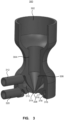
- FIG. 3 depicts a further illustrative 3D print head attachment.
- the print head attachment described above with regard to FIGs. 2A and 2B may provide acceptable printing results, however the mist delivery channel and openings as well as the extraction channel and openings may not provide desired printing results.
- the print head attachment described further below with reference to FIG. 3 and FIG. 4 has an improved shape of the mist delivery channel for promoting the laminar flow of the cross-linker mist 360° about the extruded print material.
- the print head attachment has an improved shape of the mist extraction channel to reduce disruption of the laminar flow of the cross-linker mist about the extruded print material while still removing the excess cross-linker from the print area.
- the print head attachment 300 may be formed as a single unitary piece of material having various channels and openings formed within it.
- the print head attachment may be formed using various manufacturing techniques including 3D printing and injection molding.
- the particular shape and size of the print head attachment may be varied according to the particular print head the attachment is designed for.
- the print head attachment 300 has a receiver opening 302 into which a print head, such as a syringe can be received.
- the receiver opening 302 continues through the body as cylindrical body opening 304 for receiving a portion of the print head.
- the receiver opening and body opening may continue through a conical opening portion 306 for receiving a portion of the print head, such as a cone-tip needle attachment.
- the exit nozzle of the print head may extend through the conical opening and through an exit opening 308.
- the exit nozzle of the print head may extend fully through the exit opening 308, or it may remain within the exit opening 308, or even within the conical opening 306.
- the print head attachment 300 comprises a mist delivery channel 310.
- the delivery channel may be formed about a vertical axis of the body to provide a continuous 360° channel.
- the delivery channel 310 is connected to a delivery connection port 312 that allows a tube or hose to be connected to the print head attachment for providing a flow of cross-linker mist into the delivery channel 310.
- the delivery channel 310 is in proximity to the exit nozzle of the print head when it is present, and supplies a flow of atomized cross-linker around the printing material extruded through the print head.
- the delivery channel 310 is depicted as having a substantially continuous opening 314 that substantially surrounds the exit opening 308, however, it is possible to provide a plurality of discreet openings surrounding the exit opening 308.
- the delivery channel 310 may have a cross sectional profile that descends downward at an angle of between 30 - 45 ° toward the delivery opening 314 to impart downward movement to the mist flow and promote laminar flow about the extruded print material.
- the channel profile may have an enlarged upper chamber with the connection port 312 located towards a top of the enlarged upper chamber, which may help provide a better flow of cross-linker out of the delivery opening 314.
- the print head attachment 300 further comprises a mist extraction channel 316 that extracts excess cross-linker from the print area. Similar to the delivery channel, the extraction channel 316 may be formed about the vertical axis of the body to provide a continuous 360° channel. The extraction channel 316 is arranged in proximity to the exit nozzle of the print syringe when present to extract a flow of excess cross-linker from around the extruded printing material.
- the extraction channel 316 may have a substantially continuous extraction opening 318 that that substantially surrounds the exit opening 308, however, it is possible to provide a plurality of discreet extraction openings surrounding the exit opening 308. The extraction opening may be spaced apart circumferentially from the exit opening 308.
- the bottom surface of the attachment between the extraction opening 318 and the exit opening 308 may have an arcuate profile 320 for helping with the extraction of excess cross linker from the print area.
- An extraction connection port 322 is connected to the extraction channel and allows a vacuum pump to be connected in order to extract the excess cross linker.
- FIG. 4 depicts a cross section of the print head attachment of FIG. 3 .
- a print head 402 is received within the opening 302, cylindrical body opening 304, conical opening 306, and through the exit opening 308.
- the exit nozzle of the print head extends past the exit opening, however the exit nozzle may remain within the print head attachment.
- the print head is controlled to extrude the printing material 404 onto a printing platform 406.
- the printing material is contacted with a flow of cross-linker mist, depicted by arrow 408.
- the mist of cross-linker is supplied through the connection port 312 into the delivery channel 310 and out the delivery opening 314 located in proximity to the nozzle exit.
- the shape of the delivery channel 310 helps to promote a laminar flow of the cross-linker mist down and around the printing material as it is extruded.
- the excess cross-linker mist that remains in the print area is extracted by the extraction channel 316 as depicted by arrows 410 through the extraction opening 318.
- the extraction profile 320 at the bottom of the print head attachment may help to extract the excess cross-linker without disturbing the flow of the cross-linker around the extruded printing material.
- a print head attachment system as described above can be easily connected to existing print heads.
- the print heads may print an object by extruding a filament of a printing material.
- the extruded filament may have a wide range of sizes, such as for example between about 20 microns and about 2000 microns.
- the print material may include various compounds or materials including for example, living cells, micro particles, nano particles, etc.
- the print head attachment can improve the printing results when printing with print materials that are exposed to cross-linkers or other coating particles.
- the cross-linker may be delivered in the form of atomized mist droplets.
- the print head attachment may be used with sodium alginate as the print material, using calcium chloride (CaCl 2 ) as the crosslinking agent to form a solid thermoset elastomer, calcium alginate.
- the print head attachment may be used with other print materials and crosslinking agents.
- Ultrasonic atomization of the cross linker creates a fine mist of droplets externally from the attachment that can be delivered to the attachment using forced airflow.
- the droplets of crosslinking agent are provided into a cavity that is designed to promote 360° laminar flow of mist about the needle tip that is focused directly on the extruded biomaterial. Excess droplets of the cross linker may be removed with an external vacuum pump.
- the attachment may fit directly onto common bioprinting equipment such as syringes and Luer-Lock dispensing needles. Mist removal may be enabled via a cavity that features a narrow channel to promote even removal of the excess mist to reduce the disruption of interaction between droplets of the crosslinking agent and the print material being extruded.
- the extraction flow rate may be set at between 3-5 L/min.
- Droplets of the cross linking agent may be generated in the diameter range of 10-100 microns using an ultrasonic atomizing system and forced into the print head at ⁇ 1 L/min (air and droplets, mixed) by an air pump.
- the temperature of the printing material may be controlled, for example within a temperature range of between 4 - 20°C, which may change viscosity of the printing material for improved printability and may enable improved diffusion of crosslinking ions.
- the attachment may fit directly onto common bioprinting equipment such as syringes and Luer-Lock dispensing needles.
- FIG. 5 shows photographs of a 3D printed cylindrical constructs.
- One cylindrical construct 502 was printed with 5 wt% sodium alginate using 10 wt% CaCl 2 mist with a flow rate of 750 mL/min from a misting attachment in accordance with the current disclosure.
- a second cylindrical construct 504 was printed with 7 wt% sodium alginate using 10 wt% CaCl 2 mist from a misting attachment in accordance with the current disclosure. Both cylindrical constructs exhibited strong layer adhesion.
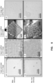
- FIG. 6 shows photographs of 3D printing results with and without mist removal using a misting attachment in accordance with the current disclosure. All other parameters of the printing remained the same and used 5 wt% sodium alginate and 10 wt% CaCl 2 mist. As can be seen in the comparison between print results depicted in panels (a) and (e), panels (b) and (f) and panels (c) and (g), the use of the mist removal during printing results in a higher quality print.
- the higher quality print results are, at least in part, a result of no or little liquid accumulation on the print stage when using the mist removal as can be seen in comparison of panels (d) and (h).
- the print head attachment and system has been described above with particular reference to supplying an atomized mist of a cross-linker around extruded print material.
- the same print head attachment and system may also be used with materials other than cross-linkers.
- the mist drops may contain the cross-linker as described above, or may contain suspensions of other particles and liquids such as a coating to be applied to the extruded material.
- the particles may be the cross-linker as described above, or may be other particles such as a coating to be applied to the extruded material.
- the coating particles may provide various functionality such as a lubricant, an adhesive, a colorant, or other particles provide desired functionality.
- the atomized mist supplied around the print material may include a combination of particles such as cross-linkers and coatings.
- the attachment may be used in various applications including fabricating tissue constructs using biocompatible polymers including sodium alginate in fabricating vascular and liver tissue, collagen in fabricating skin tissue and agarose and chitosan for various tissue engineering applications. Further, the above has described the print head attachment with respect to its use with extrusion based 3D printing. As described further below, a similar attachment may be used with other deposition processes in addition to, or as an alternative to, extrusion based 3D printing.
- Droplet-based deposition techniques can be used both as a 3D printing techniques as well as for other applications, including in pharmaceutical development, high-throughput chemical processes, etc.
- Droplet based deposition techniques may be used for 3D bioprinting and enables precise deposition of biocompatible polymers and living cells, which may be referred to as bioinks, to fabricate complex in- vitro tissue models.
- FIG. 7 depicts a misting attachment for a droplet-based deposition process.
- the misting attachment 700 is similar to the print head attachment described above.
- the misting attachment 700 may be attached to, or otherwise coupled to, a droplet deposition head 702 that deposits drops of material 704 onto a surface (not shown).
- the misting attachment 700 comprises a mist delivery channel 706 that delivers a supply of mist of crosslinker, or other suspensions of particles, around the droplets as they pass through the attachment.
- the mist delivery channel 706 may be connected to a delivery port 708 that can be used to provide a flow of the mist, whether it is a crosslinker, which could be atomized, or other suspensions of particles.
- the attachment 700 further comprises a mist extraction channel 710 through which excess mist can be extracted.
- the extraction channel 710 may be connected to an extraction port 712 that can provide a vacuum to extract the excess mist.
- the mist may enter a channel through which material droplets are deposited, as depicted by arrows 714 and then be extracted away from the droplets 704 as they are deposited as depicted by arrows 716.
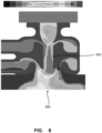
- FIG. 8 depict simulation results of mist concentration within a misting attachment in accordance with the misting attachment of FIG. 7 .
- the mist concentration is high in a path that the deposited droplets pass 802 prior to being extracted through the mist extraction channel.
- the concentration of the mist below the attachment is relatively low.
- the length between the mist delivery channel and the mist extraction channel can be set so that the material droplets are exposed to the mist for an appropriate length of time.
- the appropriate length of time may depend upon the material being deposited, the misting agent, as well as the desired properties, such as gelation amount, coating amount, etc. for a particular application.
- the flow rate and concentration of the mist may also be varied to adjust exposure levels to a desired or appropriate amount.
- the misting attachment may direct the flow of mist to provide even, 360-degree contact with the droplets as they are deposited.
- the geometry of the attachment may provide a uniform mist concentration on the centerline of the attachment, or through the path of the deposited droplets.
- the mist flowrate and concentration may be adjusted to modify the extent of exposure which may adjust the crosslinking rate. Adjusting the flowrate and concentration may be used to control the mechanical properties of the deposited materials.
- the temperature of the bioink may be adjusted (4 - 37 °C) to improve diffusion of the crosslinker mist if desired.
- the crosslinker, or the suspended particles may be collected within the attachment device to prevent accumulation of liquid on the print stage.
- the geometry of the outlet channel may prevent disruption to the printed droplets as they exit the attachment.
- the misting attachment for droplet-based deposition techniques may be used in a variety of applications, including for example, fabricating tissue spheroids for in-vitro tissue and organ regeneration, printing or otherwise manufacturing biocompatible beads for drug delivery, coating bioprinted droplets with functional substances (i.e. conductive, hydrophilic, hydrophobic).
- functional substances i.e. conductive, hydrophilic, hydrophobic
- FIG. 9 depicts a porous scaffold printed using the misting attachment described above with reference to FIG. 7 .
- the droplet based printing process used a 3 wt% sodium alginate with a crosslinking misting agent of 10 wt% CaCl 2 .
- the scaffold exhibits high shape fidelity and has good co-droplet adhesion.
Landscapes
- Chemical & Material Sciences (AREA)
- Engineering & Computer Science (AREA)
- Materials Engineering (AREA)
- Manufacturing & Machinery (AREA)
- Physics & Mathematics (AREA)
- Mechanical Engineering (AREA)
- Optics & Photonics (AREA)
Claims (14)
- Vernebelungsaufsatzsystem (100) zur Verwendung in einem Materialabscheidungsprozess, umfassend:einen Vernebelungsaufsatz (104, 202, 300, 700), umfassend:ein Aufnahmeteil (204, 302) zum Aufnehmen eines Abscheidungskopfs für einen 3D-Druckprozess, der eine Austrittsdüse aufweist, durch die ein Material abgeschieden werden kann;einen Nebelabgabekanal (118, 208, 310, 706) in der Nähe der Austrittsdüse des Abscheidungskopfs, sofern vorhanden, wobei der Nebelabgabekanal dazu angeordnet ist, eine Strömung aus einem Vernetzer oder einer Partikelsuspension um das durch den Abscheidungskopf abgeschiedene Material herum zuzuführen; undeinen Nebelabsaugkanal (130, 214, 316, 710) in der Nähe der Austrittsdüse des Abscheidungskopfs, sofern vorhanden, wobei der Nebelabsaugkanal dazu angeordnet ist, eine Strömung aus überschüssigem Vernetzer oder überschüssiger Partikelsuspension aus der Umgebung des abgeschiedenen Materials abzusaugen;einen Ultraschallzerstäuber (124) in einer Vernebelungskammer, der mit dem Nebelabgabekanal verbunden ist, um den zerstäubten Vernetzer oder die zerstäubte Partikelsuspension bereitzustellen;eine Luftpumpe (128), die mit der Vernebelungskammer verbunden ist, um die Strömung aus zerstäubtem Vernetzer oder zerstäubter Partikelsuspension zuzuführen; undeine Vakuumpumpe (134), die mit dem Nebelabsaugkanal verbunden, ist, um eine Saugwirkung zum Absaugen von überschüssigem Vernetzer oder überschüssiger Partikelsuspension bereitzustellen.
- Vernebelungsaufsatzsystem (100) nach Anspruch 1, wobei der Nebelabgabekanal (118, 208, 310, 706) die Austrittsdüse des Abscheidungskopfs, sofern vorhanden, im Wesentlichen umgibt.
- Vernebelungsaufsatzsystem (100) nach Anspruch 2, wobei der Hohlraum des Nebelabgabekanals (118, 208, 310, 706) eine Öffnung aufweist, die in einem nach unten gerichteten Winkel angeordnet ist, wodurch eine laminare Strömung von 360° aus zerstäubtem Vernetzer oder zerstäubter Partikelsuspension um die Austrittsdüse des Abscheidungskopfs, sofern vorhanden, herum gefördert wird.
- Vernebelungsaufsatzsystem (100) nach Anspruch 1, wobei der Absaugkanal (130, 214, 316, 710) die Austrittsdüse des Druckkopfs, sofern vorhanden, im Wesentlichen umgibt.
- Vernebelungsaufsatzsystem (100) nach Anspruch 4, das weiter ein Absaugprofil auf einer Oberfläche des Aufsatzes (104, 202, 300, 700) zwischen dem Absaugkanal (130, 214, 316, 710) und der Austrittsdüse des Druckkopfs, sofern vorhanden, umfasst.
- Vernebelungsaufsatzsystem (100) nach Anspruch 5, wobei das Absaugprofil ein bogenförmiges Profil aufweist, das die Austrittsdüse des Druckkopfs, sofern vorhanden, umgibt.
- Vernebelungsaufsatzsystem (100) nach Anspruch 1, wobei das Aufnahmeteil (204, 302) dazu angepasst ist, lösbar am Druckkopf befestigt zu werden.
- Vernebelungsaufsatzsystem (100) nach Anspruch 7, wobei der Druckkopf eine Spritze oder eine Dosiernadel umfasst.
- Vernebelungsaufsatzsystem (100) nach Anspruch 1, wobei der Abscheidungskopf einen Tröpfchenabscheidungskopf umfasst.
- Vernebelungsaufsatzsystem (100) nach Anspruch 9, wobei der Absaugkanal (130, 214, 316, 710) stromabwärts des Nebelabgabekanals (118, 208, 310, 706) um einen vorbestimmten Abstand beabstandet ist, um von dem Abscheidungskopf abgeschiedene Materialtröpfchen ausreichend lange dem Vernetzer oder der Partikelsuspension auszusetzen.
- Vernebelungsaufsatzsystem (100) nach Anspruch 1, wobei der Nebelabgabekanal (118, 208, 310, 706) die Strömung aus zerstäubtem Vernetzer oder zerstäubter Partikelsuspension 360° um das von dem Abscheidungskopf abgeschiedene Material herum zuführt.
- Vernebelungsaufsatzsystem (100) nach Anspruch 1, das weiter eine Vielzahl von Nebelabgabekanälen (118, 208, 310, 706) umfasst, die kreisförmig um die Austrittsdüse herum angeordnet sind.
- Vernebelungsaufsatzsystem (100) nach Anspruch 12, wobei alle der Vielzahl von Nebelabgabekanälen (118, 208, 310, 706) miteinander in strömungstechnischer Kommunikation stehen.
- Vernebelungsaufsatzsystem (100) nach Anspruch 1, das weiter einen Zufuhrverbindungsanschluss zum Verbinden des Nebelabgabekanals (118, 208, 310, 706) mit der Zufuhr aus zerstäubtem Vernetzer oder zerstäubter Partikelsuspension umfasst.
Applications Claiming Priority (2)
| Application Number | Priority Date | Filing Date | Title |
|---|---|---|---|
| US201962884217P | 2019-08-08 | 2019-08-08 | |
| PCT/CA2020/051087 WO2021022381A1 (en) | 2019-08-08 | 2020-08-07 | 3d printing head for bioprinters |
Publications (3)
| Publication Number | Publication Date |
|---|---|
| EP4010174A1 EP4010174A1 (de) | 2022-06-15 |
| EP4010174A4 EP4010174A4 (de) | 2023-08-16 |
| EP4010174B1 true EP4010174B1 (de) | 2025-02-26 |
Family
ID=74502389
Family Applications (1)
| Application Number | Title | Priority Date | Filing Date |
|---|---|---|---|
| EP20850844.0A Active EP4010174B1 (de) | 2019-08-08 | 2020-08-07 | 3d-druckkopf für biodrucker |
Country Status (5)
| Country | Link |
|---|---|
| US (1) | US12257775B2 (de) |
| EP (1) | EP4010174B1 (de) |
| JP (1) | JP7587286B2 (de) |
| CA (1) | CA3147215A1 (de) |
| WO (1) | WO2021022381A1 (de) |
Families Citing this family (3)
| Publication number | Priority date | Publication date | Assignee | Title |
|---|---|---|---|---|
| US12257775B2 (en) | 2019-08-08 | 2025-03-25 | University Of Prince Edward Island | 3D printing head for bioprinters |
| US20240165879A1 (en) * | 2021-03-26 | 2024-05-23 | University Of Connecticut | Multi-material bioprinting |
| US20260014628A1 (en) * | 2023-10-02 | 2026-01-15 | Lawrence Livermore National Security, Llc | Systems and methods for piezo-driven jetting of powders for controlled packing density in additive manufacturing applications |
Family Cites Families (14)
| Publication number | Priority date | Publication date | Assignee | Title |
|---|---|---|---|---|
| US5940674A (en) * | 1997-04-09 | 1999-08-17 | Massachusetts Institute Of Technology | Three-dimensional product manufacture using masks |
| US8342833B2 (en) * | 2009-03-31 | 2013-01-01 | Microjet Technology Co., Ltd. | Three-dimensional object forming apparatus |
| DE102012006048A1 (de) * | 2012-03-27 | 2013-10-02 | Kraussmaffei Technologies Gmbh | Vorrichtung und Verfahren zum Aufbringen eines aus wenigstens zwei Komponenten bestehenden, reaktiven Gemisches auf ein Trägermaterial |
| US20150201500A1 (en) * | 2014-01-12 | 2015-07-16 | Zohar SHINAR | System, device, and method of three-dimensional printing |
| EP3194146A4 (de) | 2014-08-05 | 2018-05-09 | Laing O'Rourke Australia Pty Limited | Vorrichtung zur herstellung eines objekts |
| US10400119B2 (en) * | 2015-05-07 | 2019-09-03 | Ehsan Toyserkani | Method and apparatus for aerosol-based three-dimensional (3D) printing of flexible graphene electronic devices |
| GB201519730D0 (en) * | 2015-11-09 | 2015-12-23 | Univ Dublin | A method, system and device for three dimensional additive manufacturing in a liquid phase |
| CN105647801B (zh) * | 2015-12-30 | 2018-06-19 | 四川蓝光英诺生物科技股份有限公司 | 生物打印机喷头组件及生物打印机 |
| WO2017210663A1 (en) | 2016-06-03 | 2017-12-07 | Paul Gatenholm | Preparation and applications of rgd conjugated polysaccharide bioinks with or without fibrin for 3d bioprinting of human skin with novel printing head for use as model for testing cosmetics and for transplantation |
| CN106222085B (zh) * | 2016-07-28 | 2019-03-12 | 西安交通大学 | 一种高精度的生物复合3d打印装置及打印方法 |
| CN110891764B (zh) | 2017-03-15 | 2022-04-26 | 安斯百克特生物系统公司 | 用于打印纤维结构的系统和方法 |
| US10081129B1 (en) | 2017-12-29 | 2018-09-25 | Cc3D Llc | Additive manufacturing system implementing hardener pre-impregnation |
| GB201902862D0 (en) * | 2019-03-04 | 2019-04-17 | Univ Dublin | A print head and insert for use with a three-dimensional bioprinter |
| US12257775B2 (en) | 2019-08-08 | 2025-03-25 | University Of Prince Edward Island | 3D printing head for bioprinters |
-
2020
- 2020-08-07 US US17/632,682 patent/US12257775B2/en active Active
- 2020-08-07 JP JP2022507815A patent/JP7587286B2/ja active Active
- 2020-08-07 WO PCT/CA2020/051087 patent/WO2021022381A1/en not_active Ceased
- 2020-08-07 EP EP20850844.0A patent/EP4010174B1/de active Active
- 2020-08-07 CA CA3147215A patent/CA3147215A1/en active Pending
Also Published As
| Publication number | Publication date |
|---|---|
| CA3147215A1 (en) | 2021-02-11 |
| EP4010174A1 (de) | 2022-06-15 |
| US20220274332A1 (en) | 2022-09-01 |
| EP4010174A4 (de) | 2023-08-16 |
| US12257775B2 (en) | 2025-03-25 |
| JP7587286B2 (ja) | 2024-11-20 |
| JP2022543166A (ja) | 2022-10-07 |
| WO2021022381A1 (en) | 2021-02-11 |
Similar Documents
| Publication | Publication Date | Title |
|---|---|---|
| US12257775B2 (en) | 3D printing head for bioprinters | |
| Costantini et al. | Co-axial wet-spinning in 3D bioprinting: state of the art and future perspective of microfluidic integration | |
| RU2643138C2 (ru) | Система и способ аддитивного производства трехмерных структур | |
| Landers et al. | Desktop manufacturing of complex objects, prototypes and biomedical scaffolds by means of computer‐assisted design combined with computer‐guided 3D plotting of polymers and reactive oligomers | |
| US11850852B2 (en) | Process and device for in-air production of single droplets, compound droplets, and shape-controlled (compound) particles or fibers | |
| CN108367488A (zh) | 用于液相中三维增材制造的方法、系统和设备 | |
| US11872745B2 (en) | Systems and methods for improved dispensing, layering, and deposition of cross-linkable hydrogels | |
| AU2020338248B2 (en) | System for manufacturing a composite fibre structure | |
| Xu et al. | Investigation of cell aggregation on the printing performance in inkjet-based bioprinting of cell-laden bioink | |
| CN105624832A (zh) | 基于微流控技术制备具球棒结构的海藻酸钙微纤维的方法 | |
| KR20210143824A (ko) | 3-차원 적층 프린팅 방법 | |
| CN106541574A (zh) | 一种基于机器人化点胶机打印装置及打印方法 | |
| CN113580491B (zh) | 可溶性微针的喷射制作设备及方法 | |
| WO2020178355A1 (en) | A three-dimensional printer comprising a print head and insert and a method of using the same | |
| Liu et al. | A review of hybrid biomanufacturing systems applied in tissue regeneration | |
| JP3191270U (ja) | 中高粘度液体材料を塗布する低吐出量用液体材料噴射バルブ | |
| Chimate et al. | Pressure assisted multi-syringe single nozzle deposition system for manufacturing of heterogeneous tissue scaffolds | |
| Biswas et al. | Introduction of 3D Printing and Different Bioprinting Methods | |
| CN116638761A (zh) | 一种3d打印装置、3d打印方法和同轴喷头 | |
| US11787915B2 (en) | Method of producing porous molded body | |
| CN219898088U (zh) | 一种用于制备粒径均一的聚乙烯醇栓塞微球的装置 | |
| KR102623703B1 (ko) | 바이오 프린터 및 제어방법 | |
| JP5846645B2 (ja) | 実装基板への水性防湿絶縁材料の塗布製造方法と塗布装置 | |
| JP6621508B1 (ja) | 吸引式微粒子コーティングを行う方法および装置 | |
| CN121496586A (zh) | 一种基于锥形容腔微流约束的核鞘纤维制备方法 |
Legal Events
| Date | Code | Title | Description |
|---|---|---|---|
| STAA | Information on the status of an ep patent application or granted ep patent |
Free format text: STATUS: THE INTERNATIONAL PUBLICATION HAS BEEN MADE |
|
| PUAI | Public reference made under article 153(3) epc to a published international application that has entered the european phase |
Free format text: ORIGINAL CODE: 0009012 |
|
| STAA | Information on the status of an ep patent application or granted ep patent |
Free format text: STATUS: REQUEST FOR EXAMINATION WAS MADE |
|
| 17P | Request for examination filed |
Effective date: 20220308 |
|
| AK | Designated contracting states |
Kind code of ref document: A1 Designated state(s): AL AT BE BG CH CY CZ DE DK EE ES FI FR GB GR HR HU IE IS IT LI LT LU LV MC MK MT NL NO PL PT RO RS SE SI SK SM TR |
|
| DAV | Request for validation of the european patent (deleted) | ||
| DAX | Request for extension of the european patent (deleted) | ||
| REG | Reference to a national code |
Ref legal event code: R079 Ipc: B29C0064209000 Ref country code: DE Ref legal event code: R079 Ref document number: 602020046930 Country of ref document: DE Free format text: PREVIOUS MAIN CLASS: B29C0064300000 Ipc: B29C0064209000 |
|
| A4 | Supplementary search report drawn up and despatched |
Effective date: 20230713 |
|
| RIC1 | Information provided on ipc code assigned before grant |
Ipc: B33Y 30/00 20150101ALI20230707BHEP Ipc: B29C 64/106 20170101ALI20230707BHEP Ipc: B29C 64/209 20170101AFI20230707BHEP |
|
| GRAP | Despatch of communication of intention to grant a patent |
Free format text: ORIGINAL CODE: EPIDOSNIGR1 |
|
| RIC1 | Information provided on ipc code assigned before grant |
Ipc: C12M 1/26 20060101ALI20240229BHEP Ipc: B33Y 30/00 20150101ALI20240229BHEP Ipc: B29C 64/106 20170101ALI20240229BHEP Ipc: B29C 64/209 20170101AFI20240229BHEP |
|
| STAA | Information on the status of an ep patent application or granted ep patent |
Free format text: STATUS: GRANT OF PATENT IS INTENDED |
|
| INTG | Intention to grant announced |
Effective date: 20240404 |
|
| GRAS | Grant fee paid |
Free format text: ORIGINAL CODE: EPIDOSNIGR3 |
|
| GRAA | (expected) grant |
Free format text: ORIGINAL CODE: 0009210 |
|
| STAA | Information on the status of an ep patent application or granted ep patent |
Free format text: STATUS: THE PATENT HAS BEEN GRANTED |
|
| AK | Designated contracting states |
Kind code of ref document: B1 Designated state(s): AL AT BE BG CH CY CZ DE DK EE ES FI FR GB GR HR HU IE IS IT LI LT LU LV MC MK MT NL NO PL PT RO RS SE SI SK SM TR |
|
| REG | Reference to a national code |
Ref country code: GB Ref legal event code: FG4D |
|
| REG | Reference to a national code |
Ref country code: CH Ref legal event code: EP |
|
| REG | Reference to a national code |
Ref country code: DE Ref legal event code: R096 Ref document number: 602020046930 Country of ref document: DE |
|
| REG | Reference to a national code |
Ref country code: IE Ref legal event code: FG4D |
|
| REG | Reference to a national code |
Ref country code: NL Ref legal event code: MP Effective date: 20250226 |
|
| PG25 | Lapsed in a contracting state [announced via postgrant information from national office to epo] |
Ref country code: RS Free format text: LAPSE BECAUSE OF FAILURE TO SUBMIT A TRANSLATION OF THE DESCRIPTION OR TO PAY THE FEE WITHIN THE PRESCRIBED TIME-LIMIT Effective date: 20250526 |
|
| PG25 | Lapsed in a contracting state [announced via postgrant information from national office to epo] |
Ref country code: FI Free format text: LAPSE BECAUSE OF FAILURE TO SUBMIT A TRANSLATION OF THE DESCRIPTION OR TO PAY THE FEE WITHIN THE PRESCRIBED TIME-LIMIT Effective date: 20250226 |
|
| PG25 | Lapsed in a contracting state [announced via postgrant information from national office to epo] |
Ref country code: PL Free format text: LAPSE BECAUSE OF FAILURE TO SUBMIT A TRANSLATION OF THE DESCRIPTION OR TO PAY THE FEE WITHIN THE PRESCRIBED TIME-LIMIT Effective date: 20250226 |
|
| PG25 | Lapsed in a contracting state [announced via postgrant information from national office to epo] |
Ref country code: ES Free format text: LAPSE BECAUSE OF FAILURE TO SUBMIT A TRANSLATION OF THE DESCRIPTION OR TO PAY THE FEE WITHIN THE PRESCRIBED TIME-LIMIT Effective date: 20250226 |
|
| REG | Reference to a national code |
Ref country code: LT Ref legal event code: MG9D |
|
| PG25 | Lapsed in a contracting state [announced via postgrant information from national office to epo] |
Ref country code: NO Free format text: LAPSE BECAUSE OF FAILURE TO SUBMIT A TRANSLATION OF THE DESCRIPTION OR TO PAY THE FEE WITHIN THE PRESCRIBED TIME-LIMIT Effective date: 20250526 Ref country code: IS Free format text: LAPSE BECAUSE OF FAILURE TO SUBMIT A TRANSLATION OF THE DESCRIPTION OR TO PAY THE FEE WITHIN THE PRESCRIBED TIME-LIMIT Effective date: 20250626 |
|
| PG25 | Lapsed in a contracting state [announced via postgrant information from national office to epo] |
Ref country code: NL Free format text: LAPSE BECAUSE OF FAILURE TO SUBMIT A TRANSLATION OF THE DESCRIPTION OR TO PAY THE FEE WITHIN THE PRESCRIBED TIME-LIMIT Effective date: 20250226 |
|
| PG25 | Lapsed in a contracting state [announced via postgrant information from national office to epo] |
Ref country code: HR Free format text: LAPSE BECAUSE OF FAILURE TO SUBMIT A TRANSLATION OF THE DESCRIPTION OR TO PAY THE FEE WITHIN THE PRESCRIBED TIME-LIMIT Effective date: 20250226 |
|
| PG25 | Lapsed in a contracting state [announced via postgrant information from national office to epo] |
Ref country code: PT Free format text: LAPSE BECAUSE OF FAILURE TO SUBMIT A TRANSLATION OF THE DESCRIPTION OR TO PAY THE FEE WITHIN THE PRESCRIBED TIME-LIMIT Effective date: 20250626 Ref country code: LV Free format text: LAPSE BECAUSE OF FAILURE TO SUBMIT A TRANSLATION OF THE DESCRIPTION OR TO PAY THE FEE WITHIN THE PRESCRIBED TIME-LIMIT Effective date: 20250226 |
|
| PG25 | Lapsed in a contracting state [announced via postgrant information from national office to epo] |
Ref country code: GR Free format text: LAPSE BECAUSE OF FAILURE TO SUBMIT A TRANSLATION OF THE DESCRIPTION OR TO PAY THE FEE WITHIN THE PRESCRIBED TIME-LIMIT Effective date: 20250527 Ref country code: BG Free format text: LAPSE BECAUSE OF FAILURE TO SUBMIT A TRANSLATION OF THE DESCRIPTION OR TO PAY THE FEE WITHIN THE PRESCRIBED TIME-LIMIT Effective date: 20250226 |
|
| REG | Reference to a national code |
Ref country code: AT Ref legal event code: MK05 Ref document number: 1770240 Country of ref document: AT Kind code of ref document: T Effective date: 20250226 |
|
| PG25 | Lapsed in a contracting state [announced via postgrant information from national office to epo] |
Ref country code: SE Free format text: LAPSE BECAUSE OF FAILURE TO SUBMIT A TRANSLATION OF THE DESCRIPTION OR TO PAY THE FEE WITHIN THE PRESCRIBED TIME-LIMIT Effective date: 20250226 |
|
| PG25 | Lapsed in a contracting state [announced via postgrant information from national office to epo] |
Ref country code: SM Free format text: LAPSE BECAUSE OF FAILURE TO SUBMIT A TRANSLATION OF THE DESCRIPTION OR TO PAY THE FEE WITHIN THE PRESCRIBED TIME-LIMIT Effective date: 20250226 |
|
| PG25 | Lapsed in a contracting state [announced via postgrant information from national office to epo] |
Ref country code: DK Free format text: LAPSE BECAUSE OF FAILURE TO SUBMIT A TRANSLATION OF THE DESCRIPTION OR TO PAY THE FEE WITHIN THE PRESCRIBED TIME-LIMIT Effective date: 20250226 |
|
| PGFP | Annual fee paid to national office [announced via postgrant information from national office to epo] |
Ref country code: DE Payment date: 20250813 Year of fee payment: 6 |
|
| PG25 | Lapsed in a contracting state [announced via postgrant information from national office to epo] |
Ref country code: IT Free format text: LAPSE BECAUSE OF FAILURE TO SUBMIT A TRANSLATION OF THE DESCRIPTION OR TO PAY THE FEE WITHIN THE PRESCRIBED TIME-LIMIT Effective date: 20250226 |
|
| PGFP | Annual fee paid to national office [announced via postgrant information from national office to epo] |
Ref country code: GB Payment date: 20250807 Year of fee payment: 6 |
|
| PG25 | Lapsed in a contracting state [announced via postgrant information from national office to epo] |
Ref country code: AT Free format text: LAPSE BECAUSE OF FAILURE TO SUBMIT A TRANSLATION OF THE DESCRIPTION OR TO PAY THE FEE WITHIN THE PRESCRIBED TIME-LIMIT Effective date: 20250226 |
|
| PGFP | Annual fee paid to national office [announced via postgrant information from national office to epo] |
Ref country code: FR Payment date: 20250808 Year of fee payment: 6 |
|
| PG25 | Lapsed in a contracting state [announced via postgrant information from national office to epo] |
Ref country code: EE Free format text: LAPSE BECAUSE OF FAILURE TO SUBMIT A TRANSLATION OF THE DESCRIPTION OR TO PAY THE FEE WITHIN THE PRESCRIBED TIME-LIMIT Effective date: 20250226 Ref country code: CZ Free format text: LAPSE BECAUSE OF FAILURE TO SUBMIT A TRANSLATION OF THE DESCRIPTION OR TO PAY THE FEE WITHIN THE PRESCRIBED TIME-LIMIT Effective date: 20250226 |
|
| PG25 | Lapsed in a contracting state [announced via postgrant information from national office to epo] |
Ref country code: RO Free format text: LAPSE BECAUSE OF FAILURE TO SUBMIT A TRANSLATION OF THE DESCRIPTION OR TO PAY THE FEE WITHIN THE PRESCRIBED TIME-LIMIT Effective date: 20250226 |
|
| PG25 | Lapsed in a contracting state [announced via postgrant information from national office to epo] |
Ref country code: SK Free format text: LAPSE BECAUSE OF FAILURE TO SUBMIT A TRANSLATION OF THE DESCRIPTION OR TO PAY THE FEE WITHIN THE PRESCRIBED TIME-LIMIT Effective date: 20250226 |
|
| REG | Reference to a national code |
Ref country code: DE Ref legal event code: R097 Ref document number: 602020046930 Country of ref document: DE |
|
| PLBE | No opposition filed within time limit |
Free format text: ORIGINAL CODE: 0009261 |
|
| STAA | Information on the status of an ep patent application or granted ep patent |
Free format text: STATUS: NO OPPOSITION FILED WITHIN TIME LIMIT |
|
| REG | Reference to a national code |
Ref country code: CH Ref legal event code: L10 Free format text: ST27 STATUS EVENT CODE: U-0-0-L10-L00 (AS PROVIDED BY THE NATIONAL OFFICE) Effective date: 20260107 |
|
| 26N | No opposition filed |
Effective date: 20251127 |
|
| REG | Reference to a national code |
Ref country code: CH Ref legal event code: H13 Free format text: ST27 STATUS EVENT CODE: U-0-0-H10-H13 (AS PROVIDED BY THE NATIONAL OFFICE) Effective date: 20260324 |
|
| PG25 | Lapsed in a contracting state [announced via postgrant information from national office to epo] |
Ref country code: MC Free format text: LAPSE BECAUSE OF FAILURE TO SUBMIT A TRANSLATION OF THE DESCRIPTION OR TO PAY THE FEE WITHIN THE PRESCRIBED TIME-LIMIT Effective date: 20250226 |
|
| PG25 | Lapsed in a contracting state [announced via postgrant information from national office to epo] |
Ref country code: LU Free format text: LAPSE BECAUSE OF NON-PAYMENT OF DUE FEES Effective date: 20250807 |
|
| PG25 | Lapsed in a contracting state [announced via postgrant information from national office to epo] |
Ref country code: CH Free format text: LAPSE BECAUSE OF NON-PAYMENT OF DUE FEES Effective date: 20250831 |