EP4010141B1 - Procédé d'allumage d'un arc de soudage - Google Patents
Procédé d'allumage d'un arc de soudage Download PDFInfo
- Publication number
- EP4010141B1 EP4010141B1 EP20739688.8A EP20739688A EP4010141B1 EP 4010141 B1 EP4010141 B1 EP 4010141B1 EP 20739688 A EP20739688 A EP 20739688A EP 4010141 B1 EP4010141 B1 EP 4010141B1
- Authority
- EP
- European Patent Office
- Prior art keywords
- welding
- wire electrode
- sde
- welding wire
- ignition
- Prior art date
- Legal status (The legal status is an assumption and is not a legal conclusion. Google has not performed a legal analysis and makes no representation as to the accuracy of the status listed.)
- Active
Links
- 238000003466 welding Methods 0.000 title claims description 242
- 238000000034 method Methods 0.000 title claims description 74
- 230000006870 function Effects 0.000 claims description 19
- 230000001133 acceleration Effects 0.000 claims description 7
- 230000008033 biological extinction Effects 0.000 claims 1
- 238000002844 melting Methods 0.000 description 15
- 230000008018 melting Effects 0.000 description 15
- 238000001514 detection method Methods 0.000 description 4
- 239000000463 material Substances 0.000 description 4
- 239000000155 melt Substances 0.000 description 3
- 238000010586 diagram Methods 0.000 description 2
- 238000005259 measurement Methods 0.000 description 2
- 238000010891 electric arc Methods 0.000 description 1
- 239000000945 filler Substances 0.000 description 1
- 238000011835 investigation Methods 0.000 description 1
- 239000007788 liquid Substances 0.000 description 1
Images


Classifications
-
- B—PERFORMING OPERATIONS; TRANSPORTING
- B23—MACHINE TOOLS; METAL-WORKING NOT OTHERWISE PROVIDED FOR
- B23K—SOLDERING OR UNSOLDERING; WELDING; CLADDING OR PLATING BY SOLDERING OR WELDING; CUTTING BY APPLYING HEAT LOCALLY, e.g. FLAME CUTTING; WORKING BY LASER BEAM
- B23K9/00—Arc welding or cutting
- B23K9/06—Arrangements or circuits for starting the arc, e.g. by generating ignition voltage, or for stabilising the arc
- B23K9/067—Starting the arc
-
- B—PERFORMING OPERATIONS; TRANSPORTING
- B23—MACHINE TOOLS; METAL-WORKING NOT OTHERWISE PROVIDED FOR
- B23K—SOLDERING OR UNSOLDERING; WELDING; CLADDING OR PLATING BY SOLDERING OR WELDING; CUTTING BY APPLYING HEAT LOCALLY, e.g. FLAME CUTTING; WORKING BY LASER BEAM
- B23K9/00—Arc welding or cutting
- B23K9/09—Arrangements or circuits for arc welding with pulsed current or voltage
-
- B—PERFORMING OPERATIONS; TRANSPORTING
- B23—MACHINE TOOLS; METAL-WORKING NOT OTHERWISE PROVIDED FOR
- B23K—SOLDERING OR UNSOLDERING; WELDING; CLADDING OR PLATING BY SOLDERING OR WELDING; CUTTING BY APPLYING HEAT LOCALLY, e.g. FLAME CUTTING; WORKING BY LASER BEAM
- B23K9/00—Arc welding or cutting
- B23K9/06—Arrangements or circuits for starting the arc, e.g. by generating ignition voltage, or for stabilising the arc
- B23K9/073—Stabilising the arc
- B23K9/0738—Stabilising of the arc by automatic re-ignition means
Definitions
- the invention relates to a method and a device for igniting and/or reigniting a welding arc between a wire end of a consumable welding wire electrode and a workpiece.
- a method and a device for igniting an electric arc in a MIG or MAG welding process are known.
- the ignition process uses a secondary voltage source to ignite the arc, which is able to ignite it with a relatively low energy input. Only after the arc has been ignited is the system switched to a primary, more powerful voltage source.
- a welding arc burns between a workpiece and a welding wire electrode, which melts in the process and thus also serves as a filler material.
- the welding arc burns between the workpiece and the welding wire electrode and reaches temperatures of more than 4000 K. Since the welding arc acts on a very small area of the workpiece, the power density in arc welding is relatively high, enabling a high welding speed.
- the welding arc is ignited by a so-called contact ignition, whereby the welding wire electrode touches the workpiece. Due to the short circuit, a high electric current flows, which melts the welding wire electrode at its tip or at its welding wire end and ignites the welding arc.
- the end of the welding wire electrode may remain welded to the surface of the tool when it comes into contact with it, preventing the welding arc from igniting. Furthermore, the welding arc may break between the end of the welding wire and the surface of the workpiece during the welding process, making it necessary to re-ignite the welding arc.
- the thermal state of the Wire end of the welding wire electrode is not taken into account.
- the free welding wire end of the welding wire electrode is not supplied with the appropriate ignition energy, which can lead to arc breaks or welding start errors during reignition.
- This object is achieved according to the invention by a method with the features specified in patent claim 1.
- the free wire end of the meltable Welding wire electrode by cutting the welding wire electrode at a melting point.
- the welding wire electrode is severed by applying a high electric current to the welding wire electrode and/or by reducing or even making the wire feed speed negative.
- the welding wire electrode is severed by applying current and/or by reducing the wire feed speed as soon as a short circuit between the welding wire electrode and the workpiece has been detected.
- the consumable welding wire electrode is conveyed to the surface of the workpiece at a wire conveying speed while the welding arc is burning.
- an extinguishing of the welding arc is detected during the conveyance of the welding wire electrode.
- the distance travelled by the wire end of the consumable welding wire electrode created at the melting point until it comes into contact or short-circuits with the surface of the workpiece is determined as a function of the wire feed speed and/or a detected time difference.
- the distance traveled by the wire end of the consumable welding wire electrode created at the melting point until it comes into contact or short-circuits with the surface of the workpiece is determined as a function of a wire feed acceleration and a detected time difference.
- the detected time difference comprises a period of time between the time of severing the consumable welding wire electrode and/or the extinguishing of the welding arc and the time of contact or short-circuiting of the wire end of the consumable welding wire electrode with the surface of the workpiece.
- the distance or time required for the wire end of the consumable welding wire electrode to make contact or short-circuit with the surface of the workpiece is measured by sensors.
- the ignition energy for igniting and/or reigniting the welding arc is automatically set higher than a normal ignition energy with a determined increasing distance or determined increasing time period.
- associated parameter sets for welding parameters are read out from a parameter set memory and the ignition energy for ignition and/or Re-ignition of the welding arc is set according to the read parameter values of the welding parameters.
- the parameter set comprises an ignition current, I, an ignition voltage, U, and/or a pulse frequency and/or a wire feed speed, V D , and/or a wire feed acceleration, a D , of the consumable welding wire electrode during the ignition process.
- the welding process comprises an ignition phase, a process start phase and a main process phase, wherein the ignition energy of the ignition processes carried out in the different phases is adjusted according to the ignition method according to the invention.
- the ignition energy for igniting and/or reigniting the welding arc is automatically adjusted according to a stored characteristic curve as a function of the determined distance or determined time period.
- the ignition energy for igniting and/or reigniting the welding arc is determined or calculated as a function of the determined distance or determined time period.
- the current amplitude for cutting the consumable welding wire electrode is determined after detection
- Short circuit is set depending on a diameter of the welding wire electrode and/or depending on an electrical conductivity and the specific heat capacity of the welding wire electrode.
- the invention further provides, according to a second aspect, an ignition device having the features specified in claim 12.
- the invention further provides, according to a further aspect, an arc welding apparatus with an ignition device according to the second aspect of the invention.
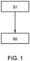
- the ignition method according to the invention for igniting and/or reigniting a welding arc SLB between a wire end of a consumable welding wire electrode SDE and a workpiece W essentially comprises two main steps, as described in Fig.1 shown schematically.
- a distance S or a time period required for the wire end of the consumable welding wire electrode SDE to come into contact or short-circuit with a surface of the workpiece W is determined.
- the welding arc SLB is ignited with an ignition energy Ez, which is set depending on the determined distance S or the determined time period.
- Ez an ignition energy
- Fig.1 The ignition process shown for igniting and/or reigniting the welding arc SLB takes into account the current thermal state of the free end of the welding wire electrode SDE. This prevents the welding wire end from being heated to too low or too high an ignition energy for igniting the welding arc. This can prevent arc breakage. Furthermore, a welding start error when igniting the welding arc SLB is avoided.
- the wire end of the consumable welding wire electrode SDE can be created by severing the welding wire electrode at a melting point SS. In one possible embodiment, this severing of the welding wire electrode SDE is brought about by applying a high electrical current I to the welding wire electrode. The severing of the welding wire electrode SDE by applying the current occurs as soon as a longer-lasting short circuit or contact between the welding wire electrode SDE and the workpiece W has been detected.
- the welding wire electrode SDE is conveyed to the surface of a workpiece W at a wire conveying speed V D while the welding arc SLB is burning. If the welding arc SLB extinguishes for conveying the welding wire electrode SDE, this can be detected in one possible embodiment.
- the distance S which a wire end of the consumable welding wire electrode formed at the melting point SS travels until it comes into contact or short-circuits with the surface of the workpiece W is determined as a function of the known wire feed speed V D and a detected time difference ⁇ t.
- the detected time difference comprises a period of time between the time of cutting through the consumable welding wire electrode SDE by current application and the time of contact or short circuit of the wire end of the consumable welding wire electrode SDE with a surface of the workpiece W or the time of ignition of the welding arc.
- the detected time difference can also include a period of time between the time of the detected extinguishing of the welding arc SLB and the time of contact or short circuit of the wire end of the consumable welding wire electrode SDE with the surface of the workpiece W or the time of ignition of the welding arc.
- the distance S or the time period W required by the wire end of the consumable welding wire electrode SDE until contact or short-circuit with the surface of the workpiece is measured by sensors.
- the ignition energy Ez for igniting or reigniting the welding arc SLB is automatically set higher with a determined increasing distance or determined increasing time period.
- the various distance values of the distance or detected time difference values of the associated parameter sets for welding parameters SP are read from a parameter set memory and the ignition energy E Z for igniting and/or reigniting the welding arc SLB is set according to the read parameter values of the welding parameters SP.
- a parameter set can include parameters such as an ignition current I, an ignition voltage U, and/or a pulse frequency and/or a wire feed speed V D and/or a wire feed acceleration a D of the consumable welding wire electrode SDE during the ignition process. Also or alternatively, parameters such as an ignition current time and/or ignition voltage time can be included.
- the parameter sets or the parameters are selected accordingly according to the set or selected welding process (such as a short-circuit welding process or a pulse welding process).
- the ignition energy Ez for igniting and/or reigniting the welding arc SLB is automatically set according to a stored characteristic curve depending on the determined distance and/or the determined time period. In one possible embodiment, the ignition energy Ez for igniting and/or reigniting the welding arc SLB is calculated by a computing unit depending on the determined distance and/or the determined time period. This is done in accordance with the selected welding process and the event. The ignition energy can be varied by up to 90% compared to a normal ignition.
- the current amplitude for cutting through the consumable welding wire electrode SDE or in the event of a detected short circuit is set depending on the diameter of the welding wire electrode SDE.
- the current amplitude for cutting through the consumable Welding wire electrode SDE can be adjusted depending on the electrical conductivity and the specific heat capacity of the welding wire electrode SDE.
- Fig.2 shows a block diagram of a possible embodiment of the ignition device 1 according to a further aspect of the invention.
- the ignition device 1 shown comprises a detection unit 2 and a setting unit 3.
- the ignition device 1 serves to ignite and/or reignite a welding arc SLB between a wire end of a consumable welding wire electrode SDE and a workpiece W, as shown in Fig.2 shown schematically.
- the welding wire electrode SDE is located on a welding torch 4 and can be unwound from a spool and conveyed towards the workpiece W. In one possible embodiment, the welding wire electrode SDE is conveyed at a predetermined, known wire conveying speed V D .
- the determination unit 2 of the ignition device 1 is designed to determine a distance S or a period of time that the wire end of the welding wire electrode SDE requires until it comes into contact or short-circuits with the surface of the workpiece W or until it ignites.
- the distance S that the wire end of the consumable welding wire electrode SDE travels until it comes into contact with the surface of the workpiece W is determined by the determination unit 2 as a function of the known wire conveying speed V D of the welding wire electrode and a detected time difference.
- the distance S which the wire end of the consumable welding wire electrode travels until contact or short circuit with the surface of the workpiece W or ignition can be determined as a function of a known wire feed acceleration a D and a detected time difference ⁇ t by the determination unit 2 is calculated.
- the detected time difference ⁇ t comprises a period of time between a time at which the consumable welding wire electrode SDE is severed by applying current and a time at which the wire end of the consumable welding wire electrode SDE comes into contact with or is short-circuited by the surface of the workpiece W or a time at which the welding arc SLB is ignited.
- the detected time difference ⁇ t can also comprise a period of time between a time at which the welding arc SLB is detected to be extinguished and a time at which the wire end of the consumable welding wire electrode SDE comes into contact with or is short-circuited by the surface of the workpiece W or a time at which the welding arc SLB is ignited.
- the distance S or a period of time that the wire end of the consumable welding wire electrode SDE needs until contact or short-circuit with the surface of the workpiece W can be measured using sensors and reported to the detection unit 2.
- the ignition device 1 has a timer or clock generator.
- the setting unit 3 of the ignition device 1 is designed to automatically set an ignition energy Ez for igniting and/or reigniting the welding arc SLB depending on the determined distance and/or the determined time period.
- the ignition energy Ez for igniting and/or reigniting the welding arc SLB is calculated depending on the determined distance S or time period.
- the ignition energy for igniting and/or reigniting the welding arc SLB is determined by the setting unit 3 at the determined increasing distance and/or increasing time period determined, the value is automatically set higher. The longer the distance or the time required, the more the wire end of the consumable welding wire electrode SDE cools down and the more cold wire is pushed in, so that a higher ignition energy Ez is required to ignite or reignite the welding wire electrode SDE.
- a read out parameter set can include an ignition current I, an ignition voltage U, a wire feed speed V D and/or wire feed acceleration a D for the consumable welding wire electrode SDE during the ignition process.
- the parameter set can additionally include a pulse frequency.
- the ignition energy Ez for igniting and/or reigniting the welding arc can be automatically set by the setting unit 3 according to a stored characteristic curve depending on the determined distance S and/or determined time period.
- the parameters in Fig. 2 The ignition device 1 shown is integrated in an arc welding device so that a welding process can be carried out. Other required components of the arc welding device, which are generally known, are not discussed here.
- Fig. 3 schematically outlines the mode of operation of the ignition device 1 according to the invention.
- a welding wire electrode SDE is conveyed at a wire conveying speed V D towards a surface of a workpiece W.
- a welding arc SLB can exist between the free wire end of the welding wire electrode SDE and the surface of the workpiece W.
- the SLB goes out due to a fault or something similar.
- the extinguishing of the SLB is symbolically represented by an "x". This event activates the path measurement.
- the wire end of the welding wire electrode SDE touches the surface of the workpiece W.
- the contact ignites the welding arc SLB.
- the contact at time t 1 can be detected.
- a slight material transfer can occur. Some material melts off the tip of the welding wire electrode SDE.
- the welding wire electrode SDE is moved to the surface of the workpiece W at a reduced feed rate V D , whereby a welding arc SLB is ignited with the ignition energy Ez which is set at least as a function of the measured distance, as in Fig. 3 shown schematically.
- the welding wire electrode SDE can also be moved away from the surface of the workpiece W at time t 2 .
- the set ignition energy Ez takes into account the thermal state of the wire end of the welding wire electrode SDE at the time of contact t 1 .
- Fig.4 outlines a situation in which, during the start of the welding process, the wire end of the welding wire electrode SDE comes into contact with the surface of the workpiece W and is welded.
- the welding wire electrode SDE moves towards the surface of the workpiece W at the known wire feed speed V D , whereby a welding arc SLB can burn; before the first ignition, no welding arc SLB is burning at time t 0 .
- the welding wire end of the welding wire electrode SDE touches the surface of the workpiece W, whereby in this case an end piece of the welding wire electrode SDE unintentionally sticks to the surface of the workpiece W.
- the adhering welding wire electrode SDE is subjected to an electrical current I b with a high current amplitude at time t 2 in order to cause the welding wire electrode SDE to be severed. Furthermore, the wire feed speed V D can be reduced at time t 2 . As in Fig.4 As shown, a new wire end of the consumable welding wire electrode SDE is created at a melting point SS at time t x . Due to the high application current I b, the lower severed part of the welding wire electrode SDE, in Fig.4 at time t x shown hatched, liquid and can splash away. This is recognized as an event and the distance measurement is started/activated.
- the newly formed welding wire end of the welding wire electrode SDE is now again conveyed at a wire conveying speed V D towards the surface of the workpiece W.
- the wire end of the welding wire electrode SDE newly formed at the melting point SS touches the surface of the workpiece W at a time t 3 , as in Fig.4
- the contact creates a welding arc SLB is ignited at time t 4.
- the new welding wire end formed at the melting point SS can, in one possible embodiment, be moved back from the surface of the workpiece W.
- the newly formed wire end of the welding wire electrode SDE at the melting point SS is heated up considerably due to the high applied current I b and is thus significantly warmer than, for example, a wire end of a welding wire electrode at the start of a welding process.
- This additional information is preferably taken into account by the setting unit 3 of the ignition device 1 for setting the ignition energy Ez at time t 3 .
- the ignition energy E Z required at time t 3 for the SLB can be set accordingly lower at t 4 .
- the ignition energy Ez is therefore preferably set not only as a function of the determined distance S or the time required for this, but also as a function of the amplitude of the severing current I b flowing at time t 2 .
- the heat or energy introduced into the welding wire electrode SDE is determined, in particular calculated based on the welding parameters and the known material properties of the welding wire electrode SDE. The higher the determined heat input, the lower the ignition energy Ez is set.
- a breaking off (event) of a welding arc SLB can be detected during the welding process.
- the time between the breaking off of the welding arc SLB and the contact or touching of the welding wire electrode SDE with the surface of the workpiece W can be measured or recorded. The longer the recorded time period, the more the end of the welding wire electrode SDE has cooled down and the higher the ignition energy Ez is set by the setting unit 3 of the ignition device 1.
- An unwanted sticking of the welding wire electrode SDE to the workpiece W occurs in conventional welding processes mainly during the first ignition process. In rare cases, when the arc breaks off, the situation can arise that after an ignition error, the welding wire end of the welding wire electrode SDE is welded or sticks to the workpiece W, as in Fig.4 shown schematically.
- the welding wire electrode SDE is preferably energized with a current I b with a high current intensity in the method according to the invention (time t 2 ).
- the welding wire electrode SDE can melt through at different positions or melting points SS.
- the welding wire electrode SDE is fed forwards towards the surface of the workpiece W.
- a new contact ignition then takes place to form a welding arc SLB using the set ignition energy Ez.
- the distance S which the Welding wire electrode SDE travels and/or the time required for this is recorded, and from this the position of the melting point or the arc break is derived. It can also be said that the path or time is recorded as a function of an event. The determined path S or recorded time difference is representative of the melting point at which the welding wire electrode was melted at time t x . From this, the required optimal ignition energy E Z can be determined or calculated.
- the ignition energy Ez can be set relatively low, since a high short-circuit current I b was used to break the short circuit and the free wire end is therefore already relatively preheated.
- the welding wire electrode SDE has melted through in the direction of the contact tube of the welding torch 4, the welding wire electrode SDE must travel a relatively long distance or a large distance S before it touches the surface of the workpiece W again, so that an increased ignition power Ez is set by the setting unit 3 for renewed ignition.
- the increased ignition power Ez is necessary because the wire end of the welding wire electrode SDE fed forward has already cooled down during the forward movement and cold wire is also fed in.
- the welding arc SLB is ignited with an ignition energy according to the method according to the invention.
- a start phase can preferably be carried out in which the parameters are also adjusted depending on the distance covered. For example, the wire feed is faster in the start phase (with a steeper ramp) when the welding arc SLB was ignited with a lower ignition energy - i.e. the welding wire was heated more.
- the ignition device 1 offers wire-thermally controlled arc ignition and takes into account in particular the current thermal state of the wire end of a welding wire electrode SDE. This allows the ignition energy Ez to be optimally adjusted for igniting or reigniting the welding arc SLB. As a result, arc breaks or welding start errors are largely avoided. The productivity of the arc welding device is increased accordingly.
Landscapes
- Engineering & Computer Science (AREA)
- Physics & Mathematics (AREA)
- Plasma & Fusion (AREA)
- Mechanical Engineering (AREA)
- Arc Welding Control (AREA)
Claims (13)
- Procédé pour amorcer et/ou réamorcer un arc de soudage (SLB) entre une extrémité de fil d'un fil-électrode de soudage fusible (SDE), et une pièce (W) après un événement, comportant les étapes consistant à :(a) déterminer (S1) une distance (S) ou une durée requise pour que l'extrémité de fil libre du fil-électrode de soudage fusible (SDE) entre en contact ou en court-circuit avec une surface de la pièce (W) ; et(b) amorcer (S2) l'arc de soudage (SLB) avec une énergie d'amorçage (Ez) réglée en fonction de la distance (S) ou de la durée déterminée.
- Procédé selon la revendication 1,
dans lequel la distance (S) couverte par l'extrémité de fil libre du fil-électrode de soudage fusible (SDE) formée au niveau d'un point de fusion (SS) jusqu'au contact ou court-circuit avec la surface de la pièce (W), est déterminée en fonction de la vitesse d'avance de fil (VD) et d'une différence de temps (Δt) détectée. - Procédé selon l'une des revendications 1 ou 2 précédentes, dans lequel la distance (S) couverte par l'extrémité de fil libre du fil-électrode de soudage fusible (SDE) formée au niveau d'un point de fusion (SS) jusqu'au contact ou court-circuit avec la surface de la pièce (W), est déterminée en fonction d'une accélération de fil (aD) et d'une différence de temps (Δt) détectée.
- Procédé selon la revendication 2 ou 3,
dans lequel la différence de temps détectée (ΔT) comprend une période de temps entre l'instant (tD) de la séparation du fil-électrode de soudage fusible (SDE) ou de l'extinction de l'arc de soudage (SLB) et l'instant du contact ou du court-circuit (tK) de l'extrémité de fil libre du fil-électrode de soudage fusible (SDE) avec la surface de la pièce (W). - Procédé selon l'une des revendications 1 à 4 précédentes, dans lequel la distance (S) ou la durée requise pour que l'extrémité de fil libre du fil-électrode de soudage fusible (SDE) entre en contact ou en court-circuit avec une surface de la pièce (W), est mesurée au moyen de capteurs.
- Procédé selon l'une des revendications 1 à 5 précédentes, dans lequel l'énergie d'amorçage (Ez) pour amorcer et/ou réamorcer l'arc de soudage (SLB) est automatiquement réglée à un niveau plus élevé lorsqu'une distance (S) croissante est déterminée ou lorsqu'une durée croissante est déterminée.
- Procédé selon l'une des revendications 1 à 6 précédentes, dans lequel pour différentes valeurs de distance de la distance (S) ou différentes valeurs de différence de temps détectées, des ensembles de paramètres associés pour des paramètres de soudage (SP) sont lus à partir d'une mémoire d'ensembles de paramètres et l'énergie d'amorçage (Ez) pour amorcer et/ou réamorcer l'arc de soudage (SLB) est réglée en fonction des valeurs de paramètres lues des paramètres de soudage (SP).
- Procédé selon la revendication 7,dans lequel l'ensemble de paramètres comprend un courant d'amorçage (I),une tension d'amorçage (U), et/ouune fréquence d'impulsion, et/ou une vitesse d'avance de fil (VD) et/ou une accélération de fil (aD) du fil-électrode de soudage fusible (SDE) pendant l'opération d'amorçage.
- Procédé selon l'une des revendications 1 à 8 précédentes, dans lequel l'énergie d'amorçage (Ez) pour amorcer et/ou réamorcer l'arc de soudage (SLB) en fonction de la distance (S) déterminée ou de la durée déterminée est réglée automatiquement en fonction d'une courbe caractéristique mémorisée.
- Procédé selon l'une des revendications 1 à 9 précédentes, dans lequel l'énergie d'amorçage (Ez) pour amorcer et/ou réamorcer l'arc de soudage (SLB) est calculée en fonction de la distance (S) ou de la durée déterminée.
- Procédé selon l'une des revendications 2 à 10 précédentes, dans lequel une amplitude de courant pour séparer le fil-électrode de soudage fusible (SDE) après un court-circuit détecté est réglée en fonction d'un diamètre du fil-électrode de soudage (SDE) de la conductance spécifique et/ou de la capacité thermique spécifique du fil-électrode de soudage (SDE).
- Dispositif d'amorçage (1) pour amorcer et/ou réamorcer un arc de soudage (SLB) entre une extrémité de fil d'un fil-électrode de soudage fusible (SDE) et une pièce (W) comportant :- une unité de détermination (2) apte à déterminer une distance (S) ou une durée requise pour que l'extrémité de fil libre du fil-électrode de soudage fusible (SDE) entre en contact ou en court-circuit avec une surface de la pièce (W) ; et- une unité de réglage (3) apte à régler une énergie d'amorçage (Ez) à amorcer et/ou réamorcer l'arc de soudage (SLB) en fonction de la distance (S) ou de la durée.
- Appareil de soudage à l'arc comportant un dispositif d'amorçage (1) selon la revendication 12 et un chalumeau de soudage (4).
Applications Claiming Priority (2)
| Application Number | Priority Date | Filing Date | Title |
|---|---|---|---|
| EP19190196.6A EP3772388A1 (fr) | 2019-08-06 | 2019-08-06 | Procédé d'allumage d'un arc de soudage |
| PCT/EP2020/069919 WO2021023485A1 (fr) | 2019-08-06 | 2020-07-14 | Procédé d'allumage d'un arc de soudage |
Publications (2)
| Publication Number | Publication Date |
|---|---|
| EP4010141A1 EP4010141A1 (fr) | 2022-06-15 |
| EP4010141B1 true EP4010141B1 (fr) | 2024-04-24 |
Family
ID=67551131
Family Applications (2)
| Application Number | Title | Priority Date | Filing Date |
|---|---|---|---|
| EP19190196.6A Withdrawn EP3772388A1 (fr) | 2019-08-06 | 2019-08-06 | Procédé d'allumage d'un arc de soudage |
| EP20739688.8A Active EP4010141B1 (fr) | 2019-08-06 | 2020-07-14 | Procédé d'allumage d'un arc de soudage |
Family Applications Before (1)
| Application Number | Title | Priority Date | Filing Date |
|---|---|---|---|
| EP19190196.6A Withdrawn EP3772388A1 (fr) | 2019-08-06 | 2019-08-06 | Procédé d'allumage d'un arc de soudage |
Country Status (6)
| Country | Link |
|---|---|
| US (1) | US20220281022A1 (fr) |
| EP (2) | EP3772388A1 (fr) |
| JP (1) | JP7340688B2 (fr) |
| KR (1) | KR102636283B1 (fr) |
| CN (1) | CN114423559A (fr) |
| WO (1) | WO2021023485A1 (fr) |
Citations (1)
| Publication number | Priority date | Publication date | Assignee | Title |
|---|---|---|---|---|
| DE4032618C2 (de) * | 1990-09-26 | 1999-12-02 | Carl Cloos Schweistechnik Gmbh | Verfahren und Anordnung zum Zünden eines elektrischen Schweiß-Lichtbogens |
Family Cites Families (8)
| Publication number | Priority date | Publication date | Assignee | Title |
|---|---|---|---|---|
| DE4330805C2 (de) * | 1993-09-10 | 2001-09-13 | Peter Puschner | Wechselstromquelle für Lichtbogenschweißprozesse |
| US6087626A (en) * | 1998-02-17 | 2000-07-11 | Illinois Tool Works Inc. | Method and apparatus for welding |
| US7173214B2 (en) * | 2004-04-01 | 2007-02-06 | Lincoln Global, Inc. | Electric arc pulse welder with short circuit control |
| AT503469B1 (de) * | 2006-04-12 | 2008-03-15 | Fronius Int Gmbh | Schweissverfahren |
| EP2269758B1 (fr) * | 2009-07-03 | 2017-05-17 | Ewm Ag | Procédé de soudage à l'arc à courant continue |
| JP2012066288A (ja) * | 2010-09-24 | 2012-04-05 | Fanuc Ltd | アークスタート時のスパッタの発生を低減するアーク溶接方法 |
| AT512836B1 (de) * | 2012-03-29 | 2014-02-15 | Fronius Int Gmbh | Schweißvorrichtung mit zwei Schweißbrennern und Schweißverfahren mit zwei Schweißprozessen |
| US9539662B2 (en) * | 2013-10-30 | 2017-01-10 | Illinois Tool Works Inc. | Extraction of arc length from voltage and current feedback |
-
2019
- 2019-08-06 EP EP19190196.6A patent/EP3772388A1/fr not_active Withdrawn
-
2020
- 2020-07-14 EP EP20739688.8A patent/EP4010141B1/fr active Active
- 2020-07-14 CN CN202080065586.3A patent/CN114423559A/zh active Pending
- 2020-07-14 JP JP2022507455A patent/JP7340688B2/ja active Active
- 2020-07-14 US US17/632,536 patent/US20220281022A1/en active Pending
- 2020-07-14 WO PCT/EP2020/069919 patent/WO2021023485A1/fr unknown
- 2020-07-14 KR KR1020227007230A patent/KR102636283B1/ko active IP Right Grant
Patent Citations (1)
| Publication number | Priority date | Publication date | Assignee | Title |
|---|---|---|---|---|
| DE4032618C2 (de) * | 1990-09-26 | 1999-12-02 | Carl Cloos Schweistechnik Gmbh | Verfahren und Anordnung zum Zünden eines elektrischen Schweiß-Lichtbogens |
Also Published As
| Publication number | Publication date |
|---|---|
| JP7340688B2 (ja) | 2023-09-07 |
| EP3772388A1 (fr) | 2021-02-10 |
| JP2022543632A (ja) | 2022-10-13 |
| WO2021023485A1 (fr) | 2021-02-11 |
| EP4010141A1 (fr) | 2022-06-15 |
| KR20220038790A (ko) | 2022-03-29 |
| KR102636283B1 (ko) | 2024-02-14 |
| US20220281022A1 (en) | 2022-09-08 |
| CN114423559A (zh) | 2022-04-29 |
Similar Documents
| Publication | Publication Date | Title |
|---|---|---|
| AT516636B1 (de) | Brenner für ein Schweißgerät | |
| EP2007542B1 (fr) | Procede de soudage d'une piece | |
| AT501124B1 (de) | Verfahren und vorrichtung zum kombinierten laser-lichtbogenschweissen | |
| DE2501928A1 (de) | Verfahren zum zuenden des lichtbogens beim schweissen mit abschmelzenden drahtelektroden | |
| EP2810733B1 (fr) | Procédé de soudage sous gaz protecteur | |
| DE1032863B (de) | Verfahren und Vorrichtung zum Lichtbogenschweissen mit mehreren Elektroden | |
| AT411442B (de) | Verfahren zum löten von werkstücken | |
| EP3116675A1 (fr) | Procédé servant soudage au tungstène et au gaz inerte | |
| EP1354659B1 (fr) | Methode d'amorçage d'un arc entre une pièce et une électrode fusible | |
| EP1922908B1 (fr) | Procede de fonctionnement d'un chalumeau au plasma de vapeur d'eau et appareil de decoupage a la vapeur d'eau | |
| EP4010141B1 (fr) | Procédé d'allumage d'un arc de soudage | |
| EP2269758B1 (fr) | Procédé de soudage à l'arc à courant continue | |
| EP0033312B1 (fr) | Dispositif de soudage à l'arc sous gaz inerte avec avance automatique du fil | |
| DE4127794A1 (de) | Verfahren und vorrichtung zur reduzierung des energieverbrauchs und minimierung der martensitbildung waehrend der verbindung eines metallenen anschlussstueckes mit einer metalloberflaeche durch zapfenloeten | |
| DE102007015835A1 (de) | Verfahren zum manuellen Zünden eines Löt- oder Schweißlichtbogens | |
| DE3932210A1 (de) | Verfahren zum zuenden eines schweisslichtbogens beim schutzgasschweissen mit nicht abschmelzender elektrode | |
| EP1062069B1 (fr) | Procede pour amorcer un arc entre une piece et une electrode fusible et dispositif permettant de mettre ledit procede en oeuvre | |
| EP2272615B1 (fr) | Conditionnement d'une électrode fusible pour le soudage à l'arc ou la brasure à l'arc sous gaz protecteur | |
| AT409468B (de) | Verfahren zum zünden eines lichtbogens zwischen einem werkstück und einer abschmelzenden elektrode | |
| EP4299227A1 (fr) | Procédé de soudage et poste de soudure | |
| AT256591B (de) | Einrichtung zum vorzugsweise automatischen WIG-Schweißen metallischer Werkstoffe | |
| EP0456976A2 (fr) | Procédé et dispositif pour fermer une capsule métallique et pour souder avec un câble en métal | |
| DE1012709B (de) | Verfahren zum Lokalisieren des Lichtbogens in Vakuum-Lichtbogenoefen | |
| DE2606854A1 (de) | Schaltungsanordnung zum zuenden eines lichtbogens fuer das elektrische lichtbogenschweissen | |
| DE1052010B (de) | Verfahren und Einrichtung zum Lichtbogen-Punktschweissen |
Legal Events
| Date | Code | Title | Description |
|---|---|---|---|
| STAA | Information on the status of an ep patent application or granted ep patent |
Free format text: STATUS: UNKNOWN |
|
| STAA | Information on the status of an ep patent application or granted ep patent |
Free format text: STATUS: THE INTERNATIONAL PUBLICATION HAS BEEN MADE |
|
| PUAI | Public reference made under article 153(3) epc to a published international application that has entered the european phase |
Free format text: ORIGINAL CODE: 0009012 |
|
| STAA | Information on the status of an ep patent application or granted ep patent |
Free format text: STATUS: REQUEST FOR EXAMINATION WAS MADE |
|
| 17P | Request for examination filed |
Effective date: 20220228 |
|
| AK | Designated contracting states |
Kind code of ref document: A1 Designated state(s): AL AT BE BG CH CY CZ DE DK EE ES FI FR GB GR HR HU IE IS IT LI LT LU LV MC MK MT NL NO PL PT RO RS SE SI SK SM TR |
|
| DAV | Request for validation of the european patent (deleted) | ||
| DAX | Request for extension of the european patent (deleted) | ||
| GRAP | Despatch of communication of intention to grant a patent |
Free format text: ORIGINAL CODE: EPIDOSNIGR1 |
|
| STAA | Information on the status of an ep patent application or granted ep patent |
Free format text: STATUS: GRANT OF PATENT IS INTENDED |
|
| INTG | Intention to grant announced |
Effective date: 20231128 |
|
| GRAS | Grant fee paid |
Free format text: ORIGINAL CODE: EPIDOSNIGR3 |
|
| GRAA | (expected) grant |
Free format text: ORIGINAL CODE: 0009210 |
|
| STAA | Information on the status of an ep patent application or granted ep patent |
Free format text: STATUS: THE PATENT HAS BEEN GRANTED |
|
| AK | Designated contracting states |
Kind code of ref document: B1 Designated state(s): AL AT BE BG CH CY CZ DE DK EE ES FI FR GB GR HR HU IE IS IT LI LT LU LV MC MK MT NL NO PL PT RO RS SE SI SK SM TR |
|
| REG | Reference to a national code |
Ref country code: GB Ref legal event code: FG4D Free format text: NOT ENGLISH |
|
| REG | Reference to a national code |
Ref country code: CH Ref legal event code: EP |
|
| REG | Reference to a national code |
Ref country code: DE Ref legal event code: R096 Ref document number: 502020007767 Country of ref document: DE |
|
| REG | Reference to a national code |
Ref country code: IE Ref legal event code: FG4D Free format text: LANGUAGE OF EP DOCUMENT: GERMAN |