EP4008852A1 - Stützvorrichtung zur verlegung von fliesen - Google Patents
Stützvorrichtung zur verlegung von fliesen Download PDFInfo
- Publication number
- EP4008852A1 EP4008852A1 EP21209853.7A EP21209853A EP4008852A1 EP 4008852 A1 EP4008852 A1 EP 4008852A1 EP 21209853 A EP21209853 A EP 21209853A EP 4008852 A1 EP4008852 A1 EP 4008852A1
- Authority
- EP
- European Patent Office
- Prior art keywords
- base
- dihedral angle
- separator element
- washer
- flaps
- Prior art date
- Legal status (The legal status is an assumption and is not a legal conclusion. Google has not performed a legal analysis and makes no representation as to the accuracy of the status listed.)
- Pending
Links
Images


Classifications
-
- E—FIXED CONSTRUCTIONS
- E04—BUILDING
- E04F—FINISHING WORK ON BUILDINGS, e.g. STAIRS, FLOORS
- E04F21/00—Implements for finishing work on buildings
- E04F21/0092—Separate provisional spacers used between adjacent floor or wall tiles
-
- E—FIXED CONSTRUCTIONS
- E04—BUILDING
- E04F—FINISHING WORK ON BUILDINGS, e.g. STAIRS, FLOORS
- E04F21/00—Implements for finishing work on buildings
- E04F21/18—Implements for finishing work on buildings for setting wall or ceiling slabs or plates
- E04F21/1838—Implements for finishing work on buildings for setting wall or ceiling slabs or plates for setting a plurality of similar elements
- E04F21/1844—Implements for finishing work on buildings for setting wall or ceiling slabs or plates for setting a plurality of similar elements by applying them one by one
-
- E—FIXED CONSTRUCTIONS
- E04—BUILDING
- E04F—FINISHING WORK ON BUILDINGS, e.g. STAIRS, FLOORS
- E04F21/00—Implements for finishing work on buildings
- E04F21/18—Implements for finishing work on buildings for setting wall or ceiling slabs or plates
- E04F21/1838—Implements for finishing work on buildings for setting wall or ceiling slabs or plates for setting a plurality of similar elements
- E04F21/1877—Leveling devices
Definitions
- the present invention relates to a supporting device for laying tiles, i.e. facilitating the laying of slab-like elements, such as tiles, slabs, ceramics or other materials.
- the present invention relates to a supporting device for laying tiles, which can be used at sharp edges between two tiles.
- levelling spacer devices are known in the field of supporting devices for laying tiles, configured to space two or more adjacent tiles by a predetermined distance (called joint) and to ensure that the exposed surfaces thereof are coplanar.
- levelling devices which differ essentially according to the pusher element, including wedge levelling spacer devices, screw levelling spacer devices, ring nut levelling spacer devices and ratchet levelling spacer devices.
- a need felt in the sector of laying tiles, whether they are used for floor and/or step coverings or for (vertical) wall coverings, is that of improving the relative arrangement of the tiles that constitute a sharp edge, i.e. that they are arranged tilted between each other, for example squared.
- An object of the present invention is to solve these and other needs of the prior art, with a simple, rational and low-cost solution.
- an object of the present invention is to match the edge ends of the tiles which constitute a sharp edge between them and/or to precisely and repeatably determine the joint between them.
- the invention in particular, makes available a supporting device for laying tiles comprising:
- the internal dihedral angle formed by the flaps may be a (non-zero) angle lower than 160°, preferably ranging from 110° to 85°, even more preferably ranging from 110° to 90° (with a tolerance of ⁇ 5°).
- the dihedral angle can be substantially equal to a right angle (i.e. it is equal to 90° ⁇ 5°), when the flaps are in an unperturbed position, i.e. when no thrust force (other than gravity) is acting on them.
- both flaps can be tilted (and not coplanar) with respect to the separator element by an angle (strictly lower than 180°, preferably lower than 160°, as described above), which can be the same for both flaps or different between the flaps.
- the separator element can rise along a direction parallel to a plane bisecting the dihedral angle and orthogonal to a vertex edge of the dihedral angle.
- the flaps may be at least partially flexible, for example elastically, and/or rotatably coupled to the separator element at a hinge axis (imaginary or real) parallel to or coincident with a vertex edge of the dihedral angle formed therefrom.
- the dihedral angle formed between the flaps can be variable, for example within a certain range of variability of ⁇ 20°, preferably ⁇ 10°, with respect to an opening value ranging from 90° to 150°.
- the flaps can be adapted to the real inclination of the wall surfaces forming the sharp edge that are to be covered with the tiles.
- the pusher element may be movably associated to the separator element, at least approaching from the base along a movement axis laying on a plane bisecting the dihedral angle and orthogonal to a vertex edge of the dihedral angle.
- each of the flaps comprises one first surface internal with respect to the dihedral angle and one opposite second surface external to the dihedral angle that is substantially parallel to the first surface of the same flap
- the separator element comprises a base end joined at the base peak edge wherein the second surfaces of the flaps converge.
- the separator element is connected to the base in a frangible manner, by a pre-established fracture line or section.
- the device may comprise a washer provided with a pass-through opening configured to be fitted on the separator element, so as to be interposed between the pusher element and the base.
- the washer may comprise one first surface directed towards the pusher element and one second surface directed towards the base, wherein the second surface comprises two support planes arranged at opposite parts with respect to the pass-through opening (e.g. diametrically opposite with respect to the pass-through axis of the pass-through opening), wherein the support planes are tilted between each other and/or tiltable and are configured to form an additional dihedral angle lower than the straight angle (in use, directed towards the base).
- the second surface comprises two support planes arranged at opposite parts with respect to the pass-through opening (e.g. diametrically opposite with respect to the pass-through axis of the pass-through opening), wherein the support planes are tilted between each other and/or tiltable and are configured to form an additional dihedral angle lower than the straight angle (in use, directed towards the base).
- this additional internal dihedral angle formed by the support planes may be a (non-zero) angle lower than 160°, preferably ranging from 110° to 85°, even more preferably ranging from 110° to 90° (with a tolerance of ⁇ 5°).
- this additional dihedral angle may be substantially equal to a right angle (i.e. it is equal to 90° ⁇ 5°) when the support planes are in an unperturbed position, i.e. when no thrust force (other than gravity) is acting on them.
- This additional dihedral angle formed by the support planes of the washer may, for example, be substantially congruent to the dihedral angle formed by the flaps of the base.
- the support planes are defined by surfaces of the washer that are at least partially flexible, e.g. elastically, and/or rotatably coupled to (the plate-like body forming) the washer, at a hinge axis parallel to (and eccentric to) or coincident with a central vertex (i.e. a central vertex edge) of the additional dihedral angle formed therefrom.
- each of the support planes may be individually orientable with respect to (the plate-like body that forms) the washer around a respective parallel (and eccentric) hinge axis or coincident with a central vertex, i.e. a central vertex edge, (real or virtual) of the additional dihedral angle formed therefrom.
- the first surface can be planar and orthogonal to a pass-through axis of the pass-through opening, wherein the first surface is configured to come into contact with a planar end of the pusher element.
- the separator element comprises a threaded stem which the pusher element can be screwed to.
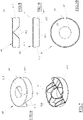
- a supporting device for laying tiles preferably configured to allow the (correct) mutual spacing and/or positioning of edges between tiles, indicated globally by the letter P, has been indicated globally by 10.
- Each tile P is adapted to be laid to cover a surface, for example at a sharp edge (i.e. preferably an external edge), so as to cover it.
- Each tile P has a large laying surface P1, for example lower or rear, and an opposite large visible surface P2, for example upper or front, preferably of homologous shape (for example polygonal, preferably quadrangular) with respect to the laying surface P1.
- a large laying surface P1 for example lower or rear
- an opposite large visible surface P2 for example upper or front, preferably of homologous shape (for example polygonal, preferably quadrangular) with respect to the laying surface P1.
- Each tile P then comprises a plurality of lateral sidewalls P3, generally squared with the laying surface P1 and the visible surface P2, which laterally delimit the same tile.
- each tile P comprises at least one lateral edge sidewall P4, which is tilted with respect to the visible surface P2 by an acute (internal) angle, for example substantially equal to 45°, preferably but not limitedly by an angle (slightly) lower than 45°, i.e. preferably equal to 43°.
- an acute (internal) angle for example substantially equal to 45°, preferably but not limitedly by an angle (slightly) lower than 45°, i.e. preferably equal to 43°.
- An apical edge P5 joining the visible surface P2 to the lateral edge sidewall P4 defines, together with another apical edge P5 homologous to an adjacent tile P (and laid squared with respect thereto), the additional sharp edge of the aforesaid covering.
- the device 10 comprises a block configured to allow the (correct) mutual spacing and/or positioning between adjacent tiles P to define a sharp edge at the respective apical edges P5 and to act as a tie rod for guiding them (so as to level the two apical edges P5) following a suitable traction action.
- the device 10 i.e., the block thereof, comprises a base 20, which is adapted in use to be placed behind the laying surface P1 of the tiles P, for example at the lateral edge sidewalls P4 thereof.
- the base 20 has a plate-like shape, that is, it consists of a plate-like body, in which the thickness is the smaller dimension of the base 20.
- the base 20 comprises, as a whole, a rear face 21, adapted to be arranged at a distance from the laying surface P1 of the tiles P installed, and an opposite front face 22, adapted to be arranged proximal to the laying surface P1 of the tiles P and, for example, at least partially in contact therewith.
- the base 20 is formed by two opposite flaps 23 joined at a median plane of base 20.
- Each of the flaps 23 defining the base 20 has a respective portion of the rear face 21 and of the front face 22.
- each flap 23 has a first internal or rear surface defining the respective rear face portion 21 of the base 20 and an opposite second external or front surface defining the respective front face portion 22 of the base 20.
- each flap 23 of the base 20 is defined by the mutual distance between the (portion of the) rear face 21 and the (portion of the) front face 22.
- each flap 23 (or at least a portion thereof) is in practice intended to receive in support a portion of the laying surface P1 (for laying) of at least one tile P.
- each flap 23 for this purpose, defines a support plane.
- the base 20, as a whole, is adapted to be immersed in a layer of adhesive which is intended to be covered by the tiles P, with the rear face 21 directed towards the surface to be covered and the front face 22 directed towards the overlying tiles P.
- the base 20 i.e. the flaps 23 of which it is composed
- the base 20 is defined by a monolithic body, for example made of a plastic material (obtained by injection moulding).
- the flaps 23 are tilted between each other and form a dihedral angle lower than the straight angle, wherein said dihedral angle is internal to the portions of rear face 21 of the flaps 23.
- the dihedral angle formed by the (portions of rear face 21 of the) flaps 23 is a (non-zero) angle lower than 160°, preferably ranging from 110° to 85°, even more preferably ranging from 110° to 90° (with a tolerance of ⁇ 5°).
- the dihedral angle is substantially equal to a right angle (i.e. it is equal to 90° ⁇ 5°).
- the dihedral angle formed by the flaps 23 is substantially fixed or, preferably, it is variable (so as to adapt to the real inclination of the surfaces of the walls which form the sharp edge to cover).
- the base 20 and/or the flaps 23 may be at least partially flexible, for example elastically, so as to define, preferably, at a vertex edge 210 of the dihedral angle formed therefrom, a (imaginary or real) hinge axis parallel or coincident with this vertex edge 210.
- the dihedral angle formed between the flaps 23 is configured (thanks to the aforesaid flexibility of the flaps 23) to adapt (elastically) to the width of the sharp edge angle of the surfaces to be covered, when the rear surface 21 is placed in (forced) contact against said surfaces to be covered.
- the vertex edge 210 of the dihedral angle defined by the flaps 23 (joining the portions of rear face 21 of each flap 23) is placed on the aforesaid median plane of the base 20.
- the flaps 23 are substantially congruent with each other (and symmetrical with respect to the aforesaid median plane), however, it is not excluded that they may be different from each other, for example one being longer than the other (or geometrically asymmetrical).
- each flap 23 is tilted between each other by the aforesaid dihedral angle (lower than 180°, preferably equal to 90° ⁇ 5°).
- each flap 23 is tilted between each other by the aforesaid additional explementary dihedral angle of the dihedral angle formed between the rear face portions 21 of each flap 23.
- a vertex peak 220 of the additional dihedral angle defined by the flaps 23 is placed on the aforesaid median plane of the base 20.
- the rear face 21 defines an intrados surface of the base 20 (and has a substantially concave inverted "V" profile), and, for example, the front face 22 defines an extrados surface of the base 20 (and presents a substantially convex inverted "V" profile, substantially explementary to the substantially concave inverted "V” profile defined by the rear surface 21)
- the flaps 23 are symmetrical between each other with respect to the said median plane of the base 20 (which passes through the vertex edge 210 and/or through the vertex peak 220).
- This median plane is also a plane bisecting the (internal) dihedral angle and/or the additional (external) dihedral angle defined by the flaps 23.
- each flap 23 the ends that are distal from the vertex edge 210 (and/or from the vertex peak 220) of each flap 23 (i.e., the eave ends of each flap 23) are substantially parallel to the vertex edge 210.
- each (portion of rear face 21 and/or of the front face 22 of each) flap 23 has a substantially quadrangular (e.g., rectangular) shape.
- each flap 23 may have a different shape (e.g. polygonal) and/or may consist of a plurality of beams (either separated or joined between each other), which join at said vertex edge and/or vertex peak.
- Each flap 23 has a connecting face 230 between the distal end of the respective rear face portion 21 and the distal end of the respective front face portion 22, wherein said connecting face 230 is preferably, but not limitedly, tilted with respect to the front face portion 22 of the same flap 23 by a connecting angle equal to one-half of the (internal) dihedral angle.
- the device 10, i.e. the block thereof, further comprises a separator element 30 projecting from the base 20 (in front thereof), preferably from the front face 22 of the base 20 on the side opposite with respect to the (internal) dihedral angle formed by the flaps 23 thereof.
- the separator element 30 is suitable, in use, to fit between facing lateral edge sidewalls P4 of at least two (or more) tiles P to be placed side-by-side on site in order to determine the sharp edge of the aforesaid covering (i.e. the two or more tiles that are supported with their laying surface P1 on the respective front face portion 22 of the flaps 23 of the base 20).
- the separator element 30 is configured to contact (at least partially), on opposite sides thereof, such facing lateral edge sidewalls P4 by defining the width of the interspace (or joint) between such facing lateral edge sidewalls P4, that is - mainly - between the apical edges P5 of the tiles P.
- the separator element 30 projects (starting) from the vertex peak 220 of the front face 22 of the base 20.
- the separator element 30 has a longitudinal axis of development, which is, for example, orthogonal to the vertex edge 210 (and/or to the vertex peak 220) and belongs to the median plane of the base 20, i.e. to the plane bisecting the dihedral angle formed by the flaps 23 thereof.
- the separator element 30 projects from (the vertex peak 220 of the front face 22 of) the base 20 along a direction parallel to (and coincident with) this longitudinal axis (i.e. parallel to, and preferably lying on, the plane bisecting the dihedral angle and orthogonal to the vertex edge 210 of the same dihedral angle).
- the separator element 30 joins the front face 22, at the vertex peak 220 thereof, ascending along said longitudinal axis on the opposite side of the dihedral angle (formed internally to the portions of rear face 21 of the flaps 23), that is, externally to said dihedral angle.
- the separator element 30 cuts in two (equal parts) the additional (external) dihedral angle formed internally to the front face portions 22 of the flaps 23, wherein each half of said additional dihedral angle is arranged on the side opposite with respect to the median plane of the base 20 (passing through the vertex edge 210).
- the separator element 30 comprises a plate-like parallelepiped body, for example with a substantially prevalently rectangular or trapezoidal section, which defines a thin separation wall.
- the thickness of the separator element 30 is the smaller dimension of the separator element.
- the separator element 30 has a width (width being the dimension of the separator element 30 parallel to the vertex peak 220 from which it is derived), which is lower than or equal to the width of the base 20 (i.e. the length of the vertex peak 220 and/or of the vertex edge 210 thereof).
- the separator element 30 may have areas of different thickness.
- the separator element 30 comprises, therefore, at least two opposite faces 31, at least a portion of which is planar (arranged on opposite sides with respect to said bisecting plane and/or median plane of the base 20).
- the opposite faces 31 i.e., the planar portions thereof
- the opposite faces 31 are parallel to each other, and the mutual distance between (the planar portions of) them defines a calibrated thickness of the separator element 30 which, in turn, defines the width of the joint between the lateral edge sidewalls P4 (and thus also of the apical edges P5) of the tiles P (resting on the flaps 23 of the base 20).
- Each (planar portion of) face 31 of the separator element 30 is tilted with respect to the (portion of) front face 22 of the respective (and proximal) flap 23 by an angle equal to half of the additional dihedral (external) angle.
- each (planar portion of) face 31 of the separator element 30 is tilted with respect to the (portion of) front face 22 of the respective (and proximal) flap 23 by an angle equal to half of the angle explementary to the dihedral (internal) angle defined by the base 20.
- each tile P that rests on one of the two portions of the front surface 22 of the base 20 is adapted to contact one of the faces 31 of the separator element 30 by means of a respective lateral edge sidewall P4.
- the separator element 30 has a height (understood as the dimension along the longitudinal axis) greater than the thickness of the tiles P to be laid (i.e., the distance between the visible surface P2 and the laying surface P1), so that the top of the separator element 30, once the tiles P are resting (with their laying surface P1) on the respective front face portion 22 of the base 20, protrudes superiorly (abundantly) with respect to the apical edge P5 of the tiles.
- the separator element 30 has a base end 32 preferably joined to the base 20, at the vertex peak 220 thereof, and an opposite free end 33 distal from the base 20.
- the free end 33 may have, for example, upper walls sloping from the centre towards the opposite longitudinal ends and, for example, an increased thickness with respect to the rest of the separator element 30.
- the separator element 30 is made as a single (monolithic) body with the base 20, i.e. for example obtained by moulding plastic material together with the base.
- At least a (majority) portion of the separator element 30 is connected to the base 20 in a frangible manner, for example by a pre-established fracture line or section 34.
- the separator element 30 is configured to be detached from the base 20 as a result of an imposed fracture, preferably guided and/or propagating from said pre-established fracture line or section 34.
- the pre-established fracture line or section 34 can be configured in various ways according to requirements.
- the pre-established fracture line or section 34 is configured to define a weakened area, of the thickness and/or width of the separator element 30, which is configured to fail (for example due to fragile construction) if subjected to a determined breaking load (for example impulsive).
- the pre-established fracture line or section 34 is adapted, in use, to be arranged inferiorly to the level of the apical edge P5 of the tiles P to be spaced and levelled, for example substantially at the same level as the vertex peak 220 of the upper face 22 of the base 20 that is, like in the example, slightly spaced therefrom, in practice placed on the separator element 30.
- the pre-established fracture line or section 34 is made on the separator element 30 near the vertex peak 220 of the base 20.
- the pre-established fracture line or section 34 may be made at the base end 32 defining the junction line between the separator element 30 and the vertex peak 220 of the base 20.
- the pre-established fracture line or section 34 guides and/or allows and/or defines a fracture line substantially parallel to the vertex peak 220 of the base 20.
- the portion immersed in the adhesive of the device 10 i.e. the (only) base 20 (and a small portion of the foot of the separator element 30), remains trapped (disposable) in the adhesive below the laying surface P1 of the laid tiles P.
- the pre-established fracture line or section 34 (and/or the fracture triggered by it) develops longitudinally in a direction parallel to the vertex peak 220 along the entire width of the separator element 30.
- the separator element 30 may provide one or more pass-through or blind lightening windows, for example in areas of the separator element 30 that are proximal to and/or delimited inferiorly by the vertex peak 220.
- the pre-established fracture line or section 34 has two lateral stretches, which are configured to cut (and cross) the separator element 30 (i.e., two lateral legs thereof that laterally surround the window).
- the lateral stretches of the pre-established fracture line or section 34 comprise, for example, a longitudinal cut extending longitudinally with a longitudinal axis parallel to the vertex peak 220.
- the longitudinal cut extends along a predetermined stretch of the width of the separator element 30, preferably along the entire width of one leg of the same.
- each longitudinal cut defines a respective portion of the (weakened) area having a reduced cross section, having a thickness lower than the thickness of the separator element 30 at the faces 31 thereof.
- Each pre-established fracture section or line 34 may further comprise at least one fracture trigger element, which is localized in a predetermined trigger area of the longitudinal cut along its longitudinal axis.
- the trigger element defines the trigger area of the longitudinal cut having a reduced thickness.
- This reduced thickness (localized at the trigger element) can be comprised between the zero thickness (comprised) and the thickness of the (weakened) area of the longitudinal cut (not comprised).
- the trigger element is localized near at least one axial end of the longitudinal cut.
- the trigger element is localized near at least one axial end of the longitudinal cut at a predetermined non-zero distance therefrom.
- the trigger element comprises or consists of a trigger hole passing from side to side along the entire thickness of the separator element 30, in which the pass-through axis of the trigger hole is transverse (and incident), preferably orthogonal to the longitudinal axis of the longitudinal cut, i.e. it is orthogonal to the faces 31.
- the trigger hole is for example with a constant circular section, that is it has a substantially cylindrical shape, however it is not excluded that this hole may have different shapes according to requirements.
- Each lateral stretch of the pre-established fracture section or line 34 comprises a respective (single) trigger element placed in proximity to one (only) axial end of the respective longitudinal cut, preferably the external axial end (distal from the central window).
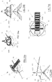
- the device 10 is of the "screw" type.
- the block i.e. the separator element 30 thereof, comprises a threaded stem 40, for example provided with a male thread 41, which projects from the free end 33 of the separator element 30, axially extending the same.
- the threaded stem 40 comprises a base end joined to (and derived from) the free end 33 of the separator element 30 and an axially opposite free top end.
- the screwing axis of the threaded stem 40 is parallel (and coincident) with the longitudinal axis of the separator element, i.e. it is orthogonal to the vertex edge 210 (and/or to the vertex peak 220) and belongs to the plane bisecting the dihedral angle formed by the flaps 23 of the base 20.
- the male thread 41 extends, for example, substantially along the entire length of the threaded stem 40 and, for example, has a constant pitch.
- the threaded stem 40 in the example has a substantially double length with respect to the height of the separator element 30.
- the threaded stem 40 is made in a single (monolithic) body with the separator element 30 (and the block 20), that is for example obtained by plastic moulding together with the base.
- the device 10 further comprises a pusher element 50 adapted to cooperate with the separator element 30, i.e. to exert a traction action on it, as will become clearer in the following description.
- the pusher element 50 is defined by a body that is separate from the block, and configured to cooperate with it.
- the pusher element 50 in the examples shown is defined, as a whole, by a monolithic body, for example made of a plastic material (obtained by injection moulding).
- the pusher element 50 is configured to be screwed onto the threaded stem 40.
- the pusher element 50 comprises a knob 51 having a globally inverted cup or bowl shape, that is a concave shape (with concavity directed towards the base 20 installed).
- the knob 51 develops, for example, around a central axis, adapted to be placed coaxial with the threaded stem 40 when the pusher element 50 is screwed onto it, as will be better described below.
- the knob 51 has, in the example, a substantially truncated-conical or dome shape, that is, it has an enlarged (lower) end and an opposite tapered top end.
- knob 51 may have any other shape, such as for example cylindrical, like a butterfly, a handle, or other suitable shape suitable for being gripped by a hand of a person in charge of the installation for screwing it.
- the enlarged (lower) end of the knob 51 defines an inlet mouth or cavity 510, for example substantially circular (coaxial with the central axis of the knob).
- the inlet cavity 510 has, for example, an internal diameter greater than the external diameter of the male thread 41 of the threaded stem 40, so that the latter can be fitted axially with abundant radial clearance inside the inlet cavity 510 of the knob 51.
- the inlet cavity 510 has an internal diameter substantially equal to or slightly greater than the (maximum) width of the separator element 30, so that the latter (if necessary) can be fitted axially with radial clearance inside the inlet cavity 510 of the knob 51, when the pusher element 50 is screwed onto the threaded stem 40.
- the knob 51 comprises an internal shell, for example substantially smooth, and a shaped external shell.
- the external shell of the knob 51 for example, comprises projections 511 (or ridges), for example in number of 4, to facilitate the grip and the rotation actuation for screwing the knob.
- Each projection 511 has, for example, a substantially triangular shape, preferably with a side orthogonal to the inlet cavity 510 of the knob 51.
- the knob 51 can have one or more windows 512, for example pass-through or transparent windows, made at the wall which joins the enlarged (lower) end of the knob 51 with its tapered top.
- windows 512 for example pass-through or transparent windows, made at the wall which joins the enlarged (lower) end of the knob 51 with its tapered top.
- each window 512 is made at an interspace (or recess) between two adjacent projections 511.
- Each window 512 in the example, is a pass-through window in a continuous way from the external shell to the internal shell and forming a decreasing and connected ramp and, preferably, has a substantially ogival (rounded and elongated) shape, which is enlarged towards the (lower) enlarged end of the knob 51.
- knob 51 may be entirely transparent.
- the knob 51 also has a planar end 513 adapted to be directed towards the base 20 (parallel thereto) when the pusher element 50 is screwed onto the threaded stem 40 and perpendicular to the central axis of the knob 51.
- the planar end 513 actually delimits perimeterally (with full development) the inlet cavity 510 of the knob 51.
- the planar end 513 is for example substantially shaped like a circular crown, preferably defined by the base of a cylindrical shank coaxial with the central axis and deriving inferiorly from the cap (truncated-conical) portion of the knob 51.
- planar end 513 is defined by a pair of concentric circular crowns, for example each defined by the base of a cylindrical shank coaxial with the central axis, as described above.
- planar end 513 is adapted to be directed, in use, towards the base 20 (or towards the apical edge P5 of the tiles P resting on the base 20) and defines a perfectly planar annular surface perpendicular to the central axis of the knob 51.
- the knob 51 may comprise, for example at or near the planar end 513, an annular step protruding radially towards the outside of the knob, for example of the external shell thereof and (also) of the projections 511.
- the pusher element 50 particularly comprises a screw nut 515 (female thread) configured to couple (with a helical coupling) with the male thread 41 of the threaded stem 40.
- the screw nut 515 has, for example, a screwing axis coinciding with the central axis of the knob 51.
- the screw nut 515 is, for example, made at (or near) the tapered top of the knob 51.
- the screw nut 515 is defined at an upper shank which projects from the top of the knob 51, for example having a substantially truncated-conical (or cylindrical or prismatic) shape.
- the screw nut 515 passes axially from side to side said upper shank and, for example, at its internal end (i.e. the one that opens up into the internal shell of the knob 51) is provided with a lead-in taper to facilitate the axial insertion and the alignment of the threaded stem 41 with the screw nut 515.
- the screw nut 515 is, advantageously, defined by a continuous helix, preferably of a plurality of turns.
- the screw nut 515 may be defined by discontinuous stretches of one or more helices.
- the pusher element 50 in the example shown is defined, as a whole, by a monolithic body, for example made of a plastic material (obtained by injection moulding).
- the device 10 is of the "ratchet" type.
- the block i.e. the separator element 30 thereof, comprises a notched band 45 (which performs the function of the threaded stem 40 of the "screw” devices), which projects from the free end 33 of the separator element 30, extending it axially.
- the notched band 45 comprises a base end joined to (and deriving from) the free end 33 of the separator element 30 and an axially opposite free top end.
- the notches of the notched band 45 are aligned along a direction of imposed sliding that is parallel (and coincident) with the longitudinal axis of the separator element, i.e. it is orthogonal to the vertex edge 210 (and/or to the vertex peak 220) and belongs to the plane bisecting the dihedral angle formed by the flaps 23 of the base 20.
- the notches of the notched band 45 extend, for example, substantially along the entire length of the notched band and, for example, it has constant pitch.
- the notched band 45 in the example is substantially twice as long as the height of the separator element 30.
- the notched band 45 is made in a single (monolithic) body with the separator element 30 (and the block 20), that is for example obtained by moulding plastic material together with the base.
- the pusher element 50 is configured to slide along the notched band 45, engaging the same in a pop-up manner.
- the pop-up connection is unidirectional, so that the pusher element 50 can slide on the notched band 45 only when approaching the separator element 30 (and the base 20)
- the pusher element 50 comprises a cap having an overall inverted cup or bowl shape, for example truncated pyramidal, i.e. a concave shape (with concavity directed towards the base 20 installed).
- the cap may have any other shape, such as for example conical, cylindrical, like a butterfly, a handle, or other suitable shape adapted to be gripped by a hand of a person in charge of the installation for screwing it.
- the cap moreover, has a planar end (and/or of the coplanar lower feet) directed towards the base 20 (parallel thereto) when the pusher element 50 is slidingly associated on the notched band 45 and perpendicular to the longitudinal axis of the notched band.
- planar end is adapted to be directed, in use, towards the base 20 (or towards the apical edge P5 of the tiles P resting on the base 20) and defines a perfectly planar surface perpendicular to the longitudinal axis A of the separator element 30.
- the pusher element 50 comprises, in particular, a toothed slot configured to couple (with a pop-up coupling) with the teeth of the notched band 45.
- a toothed slot is defined at an upper shank projecting from the top of the cap and/or at a top wall of the cap.
- the toothed slot passes axially this top wall of the cap from side to side and, for example, at its internal end it is provided with a lead-in taper to facilitate the axial insertion and alignment of the toothed band 45 in the cap.
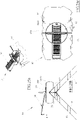
- the device 10 is of the "wedge" type.
- the block i.e. the separator element 30 thereof, at least partially delimits at least one (pass-through) window 46, which is configured to emerge above the level reached by the apical edges P5 of the tiles P resting on the portions of the upper face 22 of the base 20.
- the window 46 is delimited at the top by a bridge 47 (or crossbar), which develops parallel to the vertex peak 220 (at a non-zero distance therefrom)
- the bridge 47 is joined to the free end 33 of the separator element 30, which, in this case, is defined by a central leg or, preferably, by two separate legs which laterally delimit the window 46.
- the bridge 47 performs the function of the threaded stem 40 of the "screw" devices.
- the bridge 47 is made in a single (monolithic) body with the separator element 30 (and the base 20), i.e. for example obtained by moulding plastic material together with the base.
- the pusher element 50 is defined by a pressure wedge (e.g. separated or joined in some way to the respective block).
- a pressure wedge is a right-angled wedge, for example it is provided with a planar end defined by a flat lower surface and adapted to be directed, in use, towards the vertex peak 220 of the base 20 and an upper surface tilted with respect to the lower surface and provided, for example, with abutment elements, such as teeth or knurls.
- the pressure wedge has variable (and steadily growing) thickness along its longitudinal axis from one tapered end to the opposite widened end.
- the pressure wedge is configured to be able to be axially fitted with clearance through the window 46 of the block along an insertion direction orthogonal to the vertex peak 220 (and to the vertex edge 210) and orthogonal to the plane bisecting the dihedral angle formed by the flaps 23 of the base.
- the maximum height of the pressure wedge is lower than the height of the window 46 (i.e. the distance of the lower edge of the bridge 47 from the vertex peak 220).
- the lower edge of the bridge (directed towards the vertex peak 220) is adapted to engage the teeth of the pressure wedge substantially in a pop-up manner during the axial insertion of the pressure wedge into the window along the insertion direction.
- the pressure wedge is adapted to be fitted into the window 46 by means of a direct axial thrust parallel to the insertion direction from the side of maximum height of the pressure wedge.
- the device 10 may be of a different type, such as for example a "ring nut” device or other.
- the device 10 (for each of the above-described embodiments) further comprises a washer 60 configured to be interposed, in use, between (the surface of) the pusher element 50 (directed towards the base 20) and the (front face 22 of) the base 20 (i.e., the vertex peak 220).
- the washer 60 defines a spacer element or a spacer, which is interposed between (the surface of) the pusher element 50 (directed towards the base 20) and the (front face 22 of) the base 20 (i.e. the vertex peak 220), more specifically between (the visible surface P2 of) the tiles P (resting on the base 20) and (the surface of) the pusher element 50 (directed towards the base 20).
- the washer 60 is configured to be held stationary (as will better appear below) with respect to the visible surface P2 of the tiles P (while resting on it) while the pusher element 50 is movable (during its pressing action) with respect to the protection ring nut 60 and/or the visible surface P2 of the tiles P and/or the base 20.
- the washer 60 in the present case, defines an abutment surface for the pusher element 50 which allows the latter to exert a traction action on the block, i.e. on the separator element 30 (and/or a thrust action by the base 20 on the laying surface P1 of the tiles P resting on the flaps 23).
- the washer 60 is, on the whole, a rigid body, i.e. it is not deformable under the usual (bending) stresses to which it is subjected when installed, i.e. under the action of the pusher element 50.
- the washer 60 in this case, comprises a plate-like body 61, for example with a thin thickness, preferably of a circular shape (or of any shape according to the requirements, for example polygonal, like quadrangular or oval or other).
- the plate-like body 61 is provided with a front face (directed towards the pusher element 50, when in use) and an opposite rear face (directed towards the base 20, when in use).
- the washer 60 i.e. the plate-like body 61 thereof, comprises - at its front face - at least a first (front) surface 610 intended to be directed towards the pusher element 50, when in use.
- the first surface 610 is planar and, for example, defines a support and/or rubbing surface for the pusher element 50 (i.e., for the planar end 513 thereof).
- the first surface 610 develops along the entire front face of the washer 60 (i.e. along a prevailing portion thereof), i.e. the entire front face of the washer 60 is planar.
- the first surface 610 may only involve a portion of the front face of the washer 60.
- the front face of the washer 60 might have a lowered area (or a lowering), for example central, as shown in Figures 23a-23f .
- the lowered area extends longitudinally over an entire dimension (for example a diameter or a width or a length) of the washer 60.
- the central longitudinal axis of the lowered area coincides with a diameter of the washer 60.
- the lowered area for example, has a bottom wall defining (inside it) a supporting surface 6100 (fully developed along the central longitudinal axis of the lowered area).
- the supporting surface 6100 is, for example, wholly or at least partially planar, e.g. parallel to (and not coincident with) the first surface 610 (i.e. located at a lower level than it).
- the supporting surface 6100 is connected to the first surface 610 by means of a step.
- the lowered area is interposed between at least two lateral portions of the front face and/or of the washer 60, wherein the top wall of each lateral portion defines a respective portion of the aforesaid first (planar) surface 610.
- the top walls of the lateral portions (which define the first surface 610 as a whole) are coplanar with each other and define, as a whole, a support (and sliding) plane for (any) pusher element 50 (i.e. for the planar end 513 thereof).
- the supporting surface 6100 (defined by the bottom wall of the lowered area) is connected to each portion of the first surface 610 (defined by the top wall of each lateral portion) by a respective step, wherein, for example, each step has a raised surface that is tilted with respect to the supporting surface 6100 and to the first surface 610, for example orthogonal thereto.
- the lowered area in practice, defines a longitudinal channel (fully developed) on the front face, which is delimited below by the supporting surface 6100.
- the supporting surface 6100 defines, as a whole, an auxiliary (and sliding) support plane for a pusher element 50 (i.e. for the planar end 513 thereof), for example for a pressure wedge (as shown in the figures).
- a pusher element 50 i.e. for the planar end 513 thereof
- a pressure wedge as shown in the figures.
- the lowered area allows the (axial) insertion of a pressure wedge in those circumstances in which the thickness of the tiles P to be laid is high (compared to the height of the separator element 30).
- the planar end 513 of the pressure wedge in such a case, can slide axially (sliding) on the supporting surface 6100 by exerting a thrust orthogonal to the supporting surface on the washer 60.
- the front face of the washer 60 is configured so that at least one of the first surface 610 and the supporting surface 6100 can be selectively engaged (by defining a support and/or rubbing contact) by the pusher element 50, depending on the installation requirements.
- a pusher element 50 (provided with a screw nut 51) for a "screw" type device 10 is configured to rest (and rub) on the first surface 610 of the washer 60.
- a pusher element 50 of a pressure wedge type for a "wedge” type device is configured to selectively rest (and rub) on the first surface 610 (for an axial sliding in a direction orthogonal to the longitudinal axis of the lowered area, where provided) or on the supporting surface 6100 (for an axial sliding in a direction parallel to the longitudinal axis of the lowered area).
- a pusher element 50 (of the cap type) for a device 10 of the "ratchet" type is configured to rest on the first surface 610.
- the washer 60 is configured such that the plane defined by the first surface 610 (and/or by the supporting surface 6100), in use, is substantially parallel and/or coincident with the planar end 513 of the pusher element 50 at least when the latter is in contact (by means of its planar end) with the (first surface 610 and/or the supporting surface 6100 of the) washer.
- the washer 60 moreover, comprises a second (rear) surface 611 opposite to the first surface 610, wherein the second surface 611 is intended to be directed towards the base 20 (i.e. facing the vertex peak 220 of the front face 22 of the base 20), when in use (i.e. when the washer 60 is axially interposed between the base 20 and the pusher element 50).
- the second surface 611 of the washer 60 is adapted to come into contact with the visible surface P2 of the tiles P that are resting on the (upper surface portion 22 of each flap 23 of the) base 20 (and remain firmly anchored there during the movement of the pusher element 50 with respect to the separator element 30 and/or the base 20).
- the second surface 611 in use, is adapted to come into contact with the visible surface P2 of the tiles P that are resting on the flaps 23 of the base 20 remaining substantially integral with it (stationary, without sliding) during the movement (i.e. the screwing roto-translation or the axial or transversal sliding) of the pusher element 50 with respect to the separator element 30 (i.e. on the threaded stem 40 or on the notched band 45 or inside the window 46).
- the second surface 611 comprises at least one pair of support planes 612 which are tilted and/or tiltable between each other and which are configured to form an additional internal dihedral angle lower than the straight angle, preferably congruent with the dihedral angle formed by the (rear surface portions 21 of the) flaps 23 of the base 20.
- the additional internal dihedral angle formed by the pair of support planes 612 is a (non-zero) angle lower than 160°, preferably ranging from 110° to 85°, even more preferably ranging from 110° to 90° (with a tolerance of ⁇ 5°), for example fixed or variable.
- the additional internal dihedral angle formed by the two support planes 612 is a right angle (i.e. equal to 90° ⁇ 5°), for example fixed or variable.
- the two planes of the pair of support planes 612 join at a central vertex (real or virtual), i.e. a central vertex edge, for example defined by a squared recess (complementary to the shape of the vertex peak 220 of the base 20).
- the central vertex is parallel to the first surface 610 of the washer 60 and, for example, extends along the entire (maximum) width of the washer 60.
- the planes of the pair of support planes 612 extend in the direction parallel to their central vertex along the entire (maximum) width of the washer 60.
- the plane bisecting the additional dihedral angle formed by the pair of support planes 612 is, preferably, orthogonal to the first surface 610 of the washer 60.
- the planes of the pair of support planes 612 in use, are configured to each come into contact with the visible surface P2 of (at least) a tile P resting on a respective flap 23 of the base 20 while remaining substantially integral with it (stationary, without sliding) during the movement (i.e. the screwing roto-translation or axial or transverse sliding) of the pusher element 50 with respect to the separator element 30 (i.e. on the threaded stem 40 or on the notched band 45 or inside the window 46).
- the planes of the pair of support planes 612 are rigidly fixed to (the plate-like body 61 forming) the washer 60.
- the planes of the pair of support planes 612 can be rotatably and/or flexibly fixed to (the plate-like body 61 forming) the washer 60, for example around one or more hinge and/or folding axes that are parallel (and coinciding or eccentric) to the central vertex of the additional dihedral angle formed therefrom.
- the second surface 611 of the washer 60 may comprise, as shown in particular in Figures 23a-23f , a plurality of pairs of support planes 612 (as described above), for example in number of two pairs of support planes 612.
- the central vertex (i.e. the central vertex edge) of a pair of support planes 612 i.e. the axis on which this central vertex of the additional dihedral angle formed by a pair of support planes 612 lies (and/or the plane bisecting the additional dihedral angle formed by a pair of support planes 612) is tilted, preferably orthogonal, to the central vertex (i.e. to the central vertex edge) of the other pair of support planes 612, i.e. the axis on which this central vertex of the additional dihedral angle formed by the other pair of support planes 612 lies (and/or to the plane bisecting the additional dihedral angle formed by the other pair of support planes 612).
- a central vertex (i.e., the central vertex edge) of a pair of support planes 612 is parallel to the longitudinal axis of the lowered area of the front face (where provided).
- the washer 60 comprises a perimeter shell 613 that is derived (posteriorly) from the perimeter edge of the plate-like body 61 on the opposite side of the first surface 610, for example substantially squared with respect to it.
- the perimeter shell 613 is made in a single body with the plate-like body 61.
- the shell 613 represents a (first) anti-bending and/or anti-torsional stiffening element of the plate-like body 61 and, hence, of the washer 62.
- the perimeter shell 613 is substantially cylindrical (or prismatic, with a base homologous to the shape of the plate-like body 61).
- the perimeter shell 613 has a front axial end joined to the (perimeter edge of the) plate-like body 61 and an opposite free rear axial end.
- the rear end is substantially (but not limitedly) planar, i.e., globally lying on a plane, preferably parallel to the first surface 610 (or each of them).
- the axial wall of the rear end of the perimeter shell perimeter 613 defines at least one (end) portion of the second surface 611 of the washer 60.
- Each pair of support planes 612 may be at least partially defined at (a portion of) the axial wall of the rear end of the perimeter shell 613.
- At least two (identical) shaped cracks (inverted "V" shaped), diametrically opposite, are made, wherein the axial wall stretches of each shaped crack are tilted between each other defining between them the aforesaid additional internal dihedral angle (congruent with the dihedral angle formed between the flaps 23) and converge at a common central (squared) vertex, which is proximal to the plate-like body 61 (i.e. to the first surface 610).
- a stretch of the axial wall of each shaped crack is coplanar to an axial wall stretch of the other shaped crack, so that the axial wall stretches that are coplanar of the two shaped cracks lie on one of the support surfaces 612 of a pair of support planes 612.
- each pair of axial wall stretches which are coplanar and opposite to each other (aligned along a direction parallel to the central vertex) defines one of said (two) support planes 612 of a pair of support planes 612.
- the washer 60 comprises more than one pair of support planes 612 (e.g. two in number, preferably squared with each other), then at least one respective plurality of pairs of shaped cracks (inverted "V" shaped), diametrically opposite, are made on the perimeter shell 613, as described above.
- the washer 60 comprises one or more reinforcing walls 614 that are derived (posteriorly) from the plate-like body 61 (in areas within the perimeter edge thereof) on the opposite side of the first surface 610, e.g. substantially squared to it.
- the reinforcing walls are parallel to each other and, preferably, orthogonal to the central vertex of the additional dihedral angle formed by the support planes 612 (as shown in Figures 6-10 and Figures 13-22 ) and/or concentric with respect to a central axis of the washer 60 (orthogonal to the first surface 610).
- each reinforcing wall 614 has a rear end joined to the plate-like body and an opposite free front end.
- each reinforcing wall 614 joins at the opposite axial (lateral) ends to the perimeter shell 613.
- each reinforcing wall 614 On each reinforcing wall 614, at least one additional shaped crack (inverted "V" shaped) is made aligned with the shaped cracks made in the perimeter shell 613, wherein the axial wall stretches of the shaped crack in each reinforcing wall 614 are tilted between each other defining between them the aforesaid additional internal dihedral angle (congruent to the dihedral angle formed between the flaps 23) and converge at a common central (squared) vertex, which is proximal to the plate-like body 61 (i.e. to the first surface 610).
- An axial wall stretch of the shaped crack of each reinforcing wall 614 is coplanar to an axial wall stretch of the shaped crack of the reinforcing shell 613 on one of the support planes 612, such that each axial wall stretch of the shaped crack of each reinforcing wall 614 contributes to defining one of said (two) support planes 612 of a pair of support planes 612 (in conjunction with the coplanar axial wall stretches of the shaped cracks of the perimeter shell 613).
- each pair of support planes 612 is defined only by the reinforcing walls 614 or only by the perimeter shell 613 or, as illustrated, by both.
- each pair of support planes 612 is defined by a shaped crack (inverted "V" shaped) defining a pass-through channel (along a diameter or a dimension parallel to the first surface 610) from side to side of the washer 60.
- each pair of support planes 612 of the washer 60 is configured to define a sort of prismatic connection with the visible surface P2 of the (at least) two tiles placed resting on the flaps 23 of the base 20.
- the washer 60 i.e., the plate-like body 61 thereof, further comprises a pass-through opening 62 (passing in the axial direction).
- the pass-through opening 62 has, preferably but not limitedly, a pass-through axis orthogonal to the first surface 610, for example coaxial or central thereto.
- the pass-through axis of the pass-through opening 62 moreover, cuts (orthogonally) the central vertex of the additional dihedral angle formed between the support planes 612.
- the support planes 612 of each pair of support planes 612 are arranged on opposite sides with respect to the pass-through opening 62 (i.e. with respect to a plane on which the pass-through axis and the central vertex of the respective pair of support planes 612 lie).
- the pass- through opening 62 passes through the plate-like body 61 from side to side and is open at the upper face and the opposite lower face thereof.
- the pass-through opening 62 in the illustrated example is closed perimeterally, however, it is not excluded that it may be open, for example at a circumferential stretch thereof, actually defining a crack in the plate-like body which also cuts the perimeter shell 613.
- the pass-through opening 62 has a circular shape.
- the internal diameter (or maximum dimension) of the pass-through opening 62 is greater than the maximum diameter of the threaded stem 40 (and lower than the maximum width of the separator element 30), which can therefore be fitted axially (with radial clearance) in the pass-through opening 62, allowing the insertion of the washer 60 between the base 20 and the pusher element 50.
- the internal diameter (or maximum dimension) of the pass-through opening 62 may be greater than the maximum diameter of the threaded stem 40.
- the pass-through opening 62 may have any shape with a minimum dimension which is in any case greater than the maximum diameter of the threaded stem 40.
- the pass-through opening 62 has an elongated shape like a slit with a longitudinal axis that is radial with respect to the central axis of the washer 60 and preferably, it crosses the centre of the washer 60.
- this pass-through opening 62 shaped like a slit is centred on the axis of the washer 60.
- the longitudinal axis of the slit defining the pass-through opening 62 is parallel to the central vertex, i.e. To the central vertex edge, of a pair of support planes 612.
- this washer 62 shaped like a slit is narrow and long, with a length slightly greater than the maximum width of the separator element 30 and with a width slightly greater (for example less than twice) the thickness of the separator element 30.
- Such a pass-through opening 62 shaped like a slit is, therefore, configured to fit (with clearance) on the separator element 30 and/or on the notched band 45 and/or on the bridge 47 (and establish a prismatic connection therewith).
- the separator element 30 and/or the notched band 45 and/or the bridge 47 can be fitted axially inside the pass-through opening 62 shaped like a slit.
- This pass-through opening 62 shaped like a slit has such a dimension that even the threaded stem 40 can be fitted (with abundant clearance) axially inside, for example by presenting an enlarged central area.
- the pass-through opening 62 can be formed by two slits as described above, squared with each other, i.e. each with its own longitudinal axis parallel to the central vertex (i.e. to the central vertex edge) of a respective pair of support planes 612, in practice conforming the pass-through opening 62 as a cross.
- One of said slits therefore, has a longitudinal axis parallel to the longitudinal axis of the lowered area (where provided) and the other (which will be engaged by the separator element when the pusher element 50 is to engage the supporting surface 6100) orthogonal thereto.
- the pass-through opening 62, at the second surface 611 of the washer 60 may be surrounded by a shank protruding behind the plate-like body (concentric to the perimeter shell), which is cut by the support planes 612.
- the washer 60 is defined by a monolithic (stand-alone) body, for example made of a plastic material, preferably obtained by injection moulding.
- the operation of the device 10 is as follows.
- first tile P it is sufficient to position a first block, whose base 20 the vertex edge 210 of the same is substantially directed towards (and in contact with) the sharp edge to be covered.
- Each rear face portion 21 of the respective flap 23 is substantially directed towards (and in contact with) a wall to be covered which forms the sharp edge.
- a respective laying surface P1 of at least one tile P is laid on each front face portion 22 of the respective flap 23, so that its lateral edge sidewall P4 is substantially in contact with a respective face 31 of the separator element 30.
- At least one of the support planes 612 (or both) of the washer 60 is brought into contact with at least one tile P, so that at least one apical edge P5 (or both) is placed at the central vertex defined between them.
- the knob 51 is screwed onto the threaded stem 40 bringing the planar end 513 into contact with the first surface 610 of the washer 60.
- the installer by activating the rotation (manually or by means of a suitable tool) of the pusher element 50, for example by gripping the projections 511 with his fingers, screws the latter onto the threaded stem 40 in such a way as to exert a gradual, suitably calibrated and controllable pressure on the visible surface P2 of all the tiles P on which the second surface 611 of the washer 60 rests and, at the same time, a traction on the laying surface P1 of the same through the flaps 23 of the base 20.
- the washer 60 remains firmly integral with the tiles P while being able to slide axially (along the screwing axis).
- planar end 513 of the pusher element 50 slides on the first surface 610 of the washer 60 during the screwing rotation which enables the tightening of the pusher element 50 and - thus - the levelling of the tiles P.
- the apical edges P5 of the tiles P are aligned with the central edge and are separated from each other by a (constant and calibrated) distance defined by the mutual distance between the faces 31 of the separator element 30 interposed between them. In fact, it allows the configuration of a uniform and precise covering sharp edge.
- the cap is made to slide along the notched band bringing its planar end into contact with the first surface 610 of the washer 60.
- the installer by pushing (manually or by means of a suitable tool) the pusher element 50 in the axial direction on the notched band 45, exerts a gradual, suitably calibrated and controllable pressure on the visible surface P2 of all the tiles P on which the second surface 611 of the washer 60 rests and, at the same time, a traction on the laying surface P1 of the same through the flaps 23 of the base 20.
- the apical edges P5 of the tiles P are aligned with the central edge and are separated from each other by a (constant and calibrated) distance defined by the mutual distance between the faces 31 of the separator element 30 interposed between them. In fact, it allows the configuration of a uniform and precise covering sharp edge.
- the pressure wedge is made to slide axially (in a transverse direction, i.e. parallel to the first surface 610) within the window 46, so that its planar end is in contact with the first surface 610 of the washer 60 (as shown in Figures 18-22 and 24a-24c ) or with the supporting surface 6100 (as shown in Figures 25a - 25c ) and its tilted upper surface engages the bridge 47 in a pop-up manner.
- the installer by pushing (manually or by means of a suitable tool) the pusher element 50 in the axial (transverse) direction within the window 46, exerts a gradual, suitably calibrated and controllable pressure on the visible surface P2 of all the tiles P on which the second surface 611 of the washer 60 rests and, at the same time, a traction on the laying surface P1 of the same through the flaps 23 of the base 20.
- the apical edges P5 of the tiles P are aligned with the central edge and are separated from each other by a (constant and calibrated) distance defined by the mutual distance between the faces 31 of the separator element 30 interposed between them. In fact, it allows the configuration of a uniform and precise covering sharp edge.
- the adhesive when the adhesive has consolidated and has set on the laying surface of the tiles P, it is proceeded with breaking, for example with an impulsive force (due to a hammer or similar), the separator element 30 along the pre-established fracture line or section 34, thus removing the same separator element 30, with the pusher element 50 associated therewith, in order to be able to proceed with grouting the joints between the lateral edge sidewalls P4 of the tiles P without the base 20 being visible on the finished surface.
- breaking for example with an impulsive force (due to a hammer or similar)
- the pusher elements 50 and the washers 60 can then be reused.
Applications Claiming Priority (1)
| Application Number | Priority Date | Filing Date | Title |
|---|---|---|---|
| IT202000029930 | 2020-12-04 |
Publications (1)
| Publication Number | Publication Date |
|---|---|
| EP4008852A1 true EP4008852A1 (de) | 2022-06-08 |
Family
ID=74669382
Family Applications (1)
| Application Number | Title | Priority Date | Filing Date |
|---|---|---|---|
| EP21209853.7A Pending EP4008852A1 (de) | 2020-12-04 | 2021-11-23 | Stützvorrichtung zur verlegung von fliesen |
Country Status (2)
| Country | Link |
|---|---|
| US (1) | US20220178152A1 (de) |
| EP (1) | EP4008852A1 (de) |
Cited By (1)
| Publication number | Priority date | Publication date | Assignee | Title |
|---|---|---|---|---|
| US20230091132A1 (en) * | 2021-09-21 | 2023-03-23 | Vincenzo Caruso | Systems for leveling tiles |
Families Citing this family (1)
| Publication number | Priority date | Publication date | Assignee | Title |
|---|---|---|---|---|
| USD1001618S1 (en) * | 2021-02-23 | 2023-10-17 | Grant B Jones | Circular wedge spacer |
Citations (3)
| Publication number | Priority date | Publication date | Assignee | Title |
|---|---|---|---|---|
| EP2330261A1 (de) * | 2009-12-07 | 2011-06-08 | Meint Lingel | Fliesenjustiervorrichtung |
| CN106088559A (zh) * | 2016-07-07 | 2016-11-09 | 福建省尚云亿家居家工程有限公司 | 一种铺砖方法 |
| AU2020100861A4 (en) * | 2020-02-18 | 2020-07-02 | Invention Holdings Pty Ltd | An Accessory for Tiling |
-
2021
- 2021-11-23 EP EP21209853.7A patent/EP4008852A1/de active Pending
- 2021-12-02 US US17/540,828 patent/US20220178152A1/en not_active Abandoned
Patent Citations (3)
| Publication number | Priority date | Publication date | Assignee | Title |
|---|---|---|---|---|
| EP2330261A1 (de) * | 2009-12-07 | 2011-06-08 | Meint Lingel | Fliesenjustiervorrichtung |
| CN106088559A (zh) * | 2016-07-07 | 2016-11-09 | 福建省尚云亿家居家工程有限公司 | 一种铺砖方法 |
| AU2020100861A4 (en) * | 2020-02-18 | 2020-07-02 | Invention Holdings Pty Ltd | An Accessory for Tiling |
Cited By (1)
| Publication number | Priority date | Publication date | Assignee | Title |
|---|---|---|---|---|
| US20230091132A1 (en) * | 2021-09-21 | 2023-03-23 | Vincenzo Caruso | Systems for leveling tiles |
Also Published As
| Publication number | Publication date |
|---|---|
| US20220178152A1 (en) | 2022-06-09 |
Similar Documents
| Publication | Publication Date | Title |
|---|---|---|
| EP4008852A1 (de) | Stützvorrichtung zur verlegung von fliesen | |
| EP2549030B1 (de) | Vorrichtung zum korrekten Verlegen von Bodenfliesen | |
| US10947740B2 (en) | Levelling spacer device | |
| US10053872B2 (en) | Leveling spacer for the laying of slab products | |
| US10465394B2 (en) | Tile-levelling spacer device | |
| US9097026B2 (en) | Tool-less swing arm mechanical edge setting system and method for setting tiles and tuning lippage | |
| US20140033641A1 (en) | Auxiliary device for the installation of plate-shaped products for covering floors and/or walls | |
| EP2762658B1 (de) | Vorrichtung zur Verlegung von Fliesen | |
| EP2514886A1 (de) | Hilfsvorrichtung zur Positionierung von plattenförmigen Gegenständen zum Verlegen eines Belages und/oder Wandverkleidung | |
| US20220025662A1 (en) | Levelling spacer device for slabs | |
| US11447964B2 (en) | Levelling spacer device | |
| EP3830361A1 (de) | Nivellierungsvorrichtung für fliesen | |
| US20200318364A1 (en) | Integrally fabricated tile-leveling base and wedge | |
| RU188015U1 (ru) | Устройство для выравнивания плиток | |
| AU2019200143A1 (en) | Knob for leveling spacer for laying wall tiles, floor tiles and the like | |
| US20240110393A1 (en) | Micropoint structures for tile edge spacing | |
| EP4265865A1 (de) | Verbessertes system zum nivellieren von keramik | |
| AU2012211345A1 (en) | Auxiliary device for the installation of plate-shaped products for covering floors and/or walls | |
| CN211597620U (zh) | 瓷砖调平工具包 | |
| US11840852B1 (en) | Tile-setting lippage control | |
| KR200394297Y1 (ko) | 단열재용 인서트 | |
| CA2784633A1 (en) | Auxiliary device for the installation of plate-shaped products for covering floors and/or walls | |
| RU191079U1 (ru) | Устройство для укладки плиток | |
| US20220290446A1 (en) | Easily And Quickly Installable And Removable Tile Spacer With A Vertical Arm That Has A Loop Opening | |
| KR0121469Y1 (ko) | 건물 바닥용 인조석 물갈기 시공시 사용되는 줄눈대 세터 |
Legal Events
| Date | Code | Title | Description |
|---|---|---|---|
| PUAI | Public reference made under article 153(3) epc to a published international application that has entered the european phase |
Free format text: ORIGINAL CODE: 0009012 |
|
| STAA | Information on the status of an ep patent application or granted ep patent |
Free format text: STATUS: THE APPLICATION HAS BEEN PUBLISHED |
|
| AK | Designated contracting states |
Kind code of ref document: A1 Designated state(s): AL AT BE BG CH CY CZ DE DK EE ES FI FR GB GR HR HU IE IS IT LI LT LU LV MC MK MT NL NO PL PT RO RS SE SI SK SM TR |
|
| STAA | Information on the status of an ep patent application or granted ep patent |
Free format text: STATUS: REQUEST FOR EXAMINATION WAS MADE |
|
| 17P | Request for examination filed |
Effective date: 20221202 |
|
| RBV | Designated contracting states (corrected) |
Designated state(s): AL AT BE BG CH CY CZ DE DK EE ES FI FR GB GR HR HU IE IS IT LI LT LU LV MC MK MT NL NO PL PT RO RS SE SI SK SM TR |
|
| RIN1 | Information on inventor provided before grant (corrected) |
Inventor name: SIGHINOLFI, RICCARDO |
|
| P01 | Opt-out of the competence of the unified patent court (upc) registered |
Effective date: 20230504 |