EP4008591B1 - Bauteil mit einer leiterschicht und verfahren zur herstellung eines solchen bauteils - Google Patents
Bauteil mit einer leiterschicht und verfahren zur herstellung eines solchen bauteils Download PDFInfo
- Publication number
- EP4008591B1 EP4008591B1 EP21212171.9A EP21212171A EP4008591B1 EP 4008591 B1 EP4008591 B1 EP 4008591B1 EP 21212171 A EP21212171 A EP 21212171A EP 4008591 B1 EP4008591 B1 EP 4008591B1
- Authority
- EP
- European Patent Office
- Prior art keywords
- conductive layer
- fibers
- sheath
- conductive
- electrical
- Prior art date
- Legal status (The legal status is an assumption and is not a legal conclusion. Google has not performed a legal analysis and makes no representation as to the accuracy of the status listed.)
- Active
Links
Images


Classifications
-
- B—PERFORMING OPERATIONS; TRANSPORTING
- B60—VEHICLES IN GENERAL
- B60R—VEHICLES, VEHICLE FITTINGS, OR VEHICLE PARTS, NOT OTHERWISE PROVIDED FOR
- B60R13/00—Elements for body-finishing, identifying, or decorating; Arrangements or adaptations for advertising purposes
- B60R13/02—Internal Trim mouldings ; Internal Ledges; Wall liners for passenger compartments; Roof liners
-
- H—ELECTRICITY
- H01—ELECTRIC ELEMENTS
- H01B—CABLES; CONDUCTORS; INSULATORS; SELECTION OF MATERIALS FOR THEIR CONDUCTIVE, INSULATING OR DIELECTRIC PROPERTIES
- H01B5/00—Non-insulated conductors or conductive bodies characterised by their form
- H01B5/14—Non-insulated conductors or conductive bodies characterised by their form comprising conductive layers or films on insulating-supports
-
- B—PERFORMING OPERATIONS; TRANSPORTING
- B29—WORKING OF PLASTICS; WORKING OF SUBSTANCES IN A PLASTIC STATE IN GENERAL
- B29C—SHAPING OR JOINING OF PLASTICS; SHAPING OF MATERIAL IN A PLASTIC STATE, NOT OTHERWISE PROVIDED FOR; AFTER-TREATMENT OF THE SHAPED PRODUCTS, e.g. REPAIRING
- B29C66/00—General aspects of processes or apparatus for joining preformed parts
- B29C66/01—General aspects dealing with the joint area or with the area to be joined
- B29C66/05—Particular design of joint configurations
- B29C66/10—Particular design of joint configurations particular design of the joint cross-sections
- B29C66/11—Joint cross-sections comprising a single joint-segment, i.e. one of the parts to be joined comprising a single joint-segment in the joint cross-section
- B29C66/112—Single lapped joints
- B29C66/1122—Single lap to lap joints, i.e. overlap joints
-
- B—PERFORMING OPERATIONS; TRANSPORTING
- B29—WORKING OF PLASTICS; WORKING OF SUBSTANCES IN A PLASTIC STATE IN GENERAL
- B29C—SHAPING OR JOINING OF PLASTICS; SHAPING OF MATERIAL IN A PLASTIC STATE, NOT OTHERWISE PROVIDED FOR; AFTER-TREATMENT OF THE SHAPED PRODUCTS, e.g. REPAIRING
- B29C66/00—General aspects of processes or apparatus for joining preformed parts
- B29C66/40—General aspects of joining substantially flat articles, e.g. plates, sheets or web-like materials; Making flat seams in tubular or hollow articles; Joining single elements to substantially flat surfaces
- B29C66/47—Joining single elements to sheets, plates or other substantially flat surfaces
- B29C66/474—Joining single elements to sheets, plates or other substantially flat surfaces said single elements being substantially non-flat
-
- B—PERFORMING OPERATIONS; TRANSPORTING
- B29—WORKING OF PLASTICS; WORKING OF SUBSTANCES IN A PLASTIC STATE IN GENERAL
- B29C—SHAPING OR JOINING OF PLASTICS; SHAPING OF MATERIAL IN A PLASTIC STATE, NOT OTHERWISE PROVIDED FOR; AFTER-TREATMENT OF THE SHAPED PRODUCTS, e.g. REPAIRING
- B29C66/00—General aspects of processes or apparatus for joining preformed parts
- B29C66/70—General aspects of processes or apparatus for joining preformed parts characterised by the composition, physical properties or the structure of the material of the parts to be joined; Joining with non-plastics material
- B29C66/72—General aspects of processes or apparatus for joining preformed parts characterised by the composition, physical properties or the structure of the material of the parts to be joined; Joining with non-plastics material characterised by the structure of the material of the parts to be joined
- B29C66/729—Textile or other fibrous material made from plastics
- B29C66/7294—Non woven mats, e.g. felt
-
- B—PERFORMING OPERATIONS; TRANSPORTING
- B29—WORKING OF PLASTICS; WORKING OF SUBSTANCES IN A PLASTIC STATE IN GENERAL
- B29C—SHAPING OR JOINING OF PLASTICS; SHAPING OF MATERIAL IN A PLASTIC STATE, NOT OTHERWISE PROVIDED FOR; AFTER-TREATMENT OF THE SHAPED PRODUCTS, e.g. REPAIRING
- B29C66/00—General aspects of processes or apparatus for joining preformed parts
- B29C66/70—General aspects of processes or apparatus for joining preformed parts characterised by the composition, physical properties or the structure of the material of the parts to be joined; Joining with non-plastics material
- B29C66/73—General aspects of processes or apparatus for joining preformed parts characterised by the composition, physical properties or the structure of the material of the parts to be joined; Joining with non-plastics material characterised by the intensive physical properties of the material of the parts to be joined, by the optical properties of the material of the parts to be joined, by the extensive physical properties of the parts to be joined, by the state of the material of the parts to be joined or by the material of the parts to be joined being a thermoplastic or a thermoset
- B29C66/731—General aspects of processes or apparatus for joining preformed parts characterised by the composition, physical properties or the structure of the material of the parts to be joined; Joining with non-plastics material characterised by the intensive physical properties of the material of the parts to be joined, by the optical properties of the material of the parts to be joined, by the extensive physical properties of the parts to be joined, by the state of the material of the parts to be joined or by the material of the parts to be joined being a thermoplastic or a thermoset characterised by the intensive physical properties of the material of the parts to be joined
- B29C66/7314—Electrical and dielectric properties
- B29C66/73141—Electrical conductivity
-
- B—PERFORMING OPERATIONS; TRANSPORTING
- B29—WORKING OF PLASTICS; WORKING OF SUBSTANCES IN A PLASTIC STATE IN GENERAL
- B29C—SHAPING OR JOINING OF PLASTICS; SHAPING OF MATERIAL IN A PLASTIC STATE, NOT OTHERWISE PROVIDED FOR; AFTER-TREATMENT OF THE SHAPED PRODUCTS, e.g. REPAIRING
- B29C66/00—General aspects of processes or apparatus for joining preformed parts
- B29C66/70—General aspects of processes or apparatus for joining preformed parts characterised by the composition, physical properties or the structure of the material of the parts to be joined; Joining with non-plastics material
- B29C66/73—General aspects of processes or apparatus for joining preformed parts characterised by the composition, physical properties or the structure of the material of the parts to be joined; Joining with non-plastics material characterised by the intensive physical properties of the material of the parts to be joined, by the optical properties of the material of the parts to be joined, by the extensive physical properties of the parts to be joined, by the state of the material of the parts to be joined or by the material of the parts to be joined being a thermoplastic or a thermoset
- B29C66/739—General aspects of processes or apparatus for joining preformed parts characterised by the composition, physical properties or the structure of the material of the parts to be joined; Joining with non-plastics material characterised by the intensive physical properties of the material of the parts to be joined, by the optical properties of the material of the parts to be joined, by the extensive physical properties of the parts to be joined, by the state of the material of the parts to be joined or by the material of the parts to be joined being a thermoplastic or a thermoset characterised by the material of the parts to be joined being a thermoplastic or a thermoset
- B29C66/7392—General aspects of processes or apparatus for joining preformed parts characterised by the composition, physical properties or the structure of the material of the parts to be joined; Joining with non-plastics material characterised by the intensive physical properties of the material of the parts to be joined, by the optical properties of the material of the parts to be joined, by the extensive physical properties of the parts to be joined, by the state of the material of the parts to be joined or by the material of the parts to be joined being a thermoplastic or a thermoset characterised by the material of the parts to be joined being a thermoplastic or a thermoset characterised by the material of at least one of the parts being a thermoplastic
-
- B—PERFORMING OPERATIONS; TRANSPORTING
- B29—WORKING OF PLASTICS; WORKING OF SUBSTANCES IN A PLASTIC STATE IN GENERAL
- B29C—SHAPING OR JOINING OF PLASTICS; SHAPING OF MATERIAL IN A PLASTIC STATE, NOT OTHERWISE PROVIDED FOR; AFTER-TREATMENT OF THE SHAPED PRODUCTS, e.g. REPAIRING
- B29C66/00—General aspects of processes or apparatus for joining preformed parts
- B29C66/70—General aspects of processes or apparatus for joining preformed parts characterised by the composition, physical properties or the structure of the material of the parts to be joined; Joining with non-plastics material
- B29C66/74—Joining plastics material to non-plastics material
- B29C66/742—Joining plastics material to non-plastics material to metals or their alloys
-
- B—PERFORMING OPERATIONS; TRANSPORTING
- B29—WORKING OF PLASTICS; WORKING OF SUBSTANCES IN A PLASTIC STATE IN GENERAL
- B29C—SHAPING OR JOINING OF PLASTICS; SHAPING OF MATERIAL IN A PLASTIC STATE, NOT OTHERWISE PROVIDED FOR; AFTER-TREATMENT OF THE SHAPED PRODUCTS, e.g. REPAIRING
- B29C66/00—General aspects of processes or apparatus for joining preformed parts
- B29C66/80—General aspects of machine operations or constructions and parts thereof
- B29C66/81—General aspects of the pressing elements, i.e. the elements applying pressure on the parts to be joined in the area to be joined, e.g. the welding jaws or clamps
- B29C66/814—General aspects of the pressing elements, i.e. the elements applying pressure on the parts to be joined in the area to be joined, e.g. the welding jaws or clamps characterised by the design of the pressing elements, e.g. of the welding jaws or clamps
- B29C66/8141—General aspects of the pressing elements, i.e. the elements applying pressure on the parts to be joined in the area to be joined, e.g. the welding jaws or clamps characterised by the design of the pressing elements, e.g. of the welding jaws or clamps characterised by the surface geometry of the part of the pressing elements, e.g. welding jaws or clamps, coming into contact with the parts to be joined
- B29C66/81433—General aspects of the pressing elements, i.e. the elements applying pressure on the parts to be joined in the area to be joined, e.g. the welding jaws or clamps characterised by the design of the pressing elements, e.g. of the welding jaws or clamps characterised by the surface geometry of the part of the pressing elements, e.g. welding jaws or clamps, coming into contact with the parts to be joined being toothed, i.e. comprising several teeth or pins, or being patterned
-
- B—PERFORMING OPERATIONS; TRANSPORTING
- B29—WORKING OF PLASTICS; WORKING OF SUBSTANCES IN A PLASTIC STATE IN GENERAL
- B29C—SHAPING OR JOINING OF PLASTICS; SHAPING OF MATERIAL IN A PLASTIC STATE, NOT OTHERWISE PROVIDED FOR; AFTER-TREATMENT OF THE SHAPED PRODUCTS, e.g. REPAIRING
- B29C66/00—General aspects of processes or apparatus for joining preformed parts
- B29C66/80—General aspects of machine operations or constructions and parts thereof
- B29C66/83—General aspects of machine operations or constructions and parts thereof characterised by the movement of the joining or pressing tools
- B29C66/832—Reciprocating joining or pressing tools
- B29C66/8322—Joining or pressing tools reciprocating along one axis
-
- B—PERFORMING OPERATIONS; TRANSPORTING
- B32—LAYERED PRODUCTS
- B32B—LAYERED PRODUCTS, i.e. PRODUCTS BUILT-UP OF STRATA OF FLAT OR NON-FLAT, e.g. CELLULAR OR HONEYCOMB, FORM
- B32B27/00—Layered products comprising a layer of synthetic resin
- B32B27/12—Layered products comprising a layer of synthetic resin next to a fibrous or filamentary layer
-
- B—PERFORMING OPERATIONS; TRANSPORTING
- B32—LAYERED PRODUCTS
- B32B—LAYERED PRODUCTS, i.e. PRODUCTS BUILT-UP OF STRATA OF FLAT OR NON-FLAT, e.g. CELLULAR OR HONEYCOMB, FORM
- B32B3/00—Layered products comprising a layer with external or internal discontinuities or unevennesses, or a layer of non-planar shape; Layered products comprising a layer having particular features of form
- B32B3/02—Layered products comprising a layer with external or internal discontinuities or unevennesses, or a layer of non-planar shape; Layered products comprising a layer having particular features of form characterised by features of form at particular places, e.g. in edge regions
- B32B3/08—Layered products comprising a layer with external or internal discontinuities or unevennesses, or a layer of non-planar shape; Layered products comprising a layer having particular features of form characterised by features of form at particular places, e.g. in edge regions characterised by added members at particular parts
- B32B3/085—Layered products comprising a layer with external or internal discontinuities or unevennesses, or a layer of non-planar shape; Layered products comprising a layer having particular features of form characterised by features of form at particular places, e.g. in edge regions characterised by added members at particular parts spaced apart pieces on the surface of a layer
-
- B—PERFORMING OPERATIONS; TRANSPORTING
- B32—LAYERED PRODUCTS
- B32B—LAYERED PRODUCTS, i.e. PRODUCTS BUILT-UP OF STRATA OF FLAT OR NON-FLAT, e.g. CELLULAR OR HONEYCOMB, FORM
- B32B5/00—Layered products characterised by the non- homogeneity or physical structure, i.e. comprising a fibrous, filamentary, particulate or foam layer; Layered products characterised by having a layer differing constitutionally or physically in different parts
- B32B5/02—Layered products characterised by the non- homogeneity or physical structure, i.e. comprising a fibrous, filamentary, particulate or foam layer; Layered products characterised by having a layer differing constitutionally or physically in different parts characterised by structural features of a fibrous or filamentary layer
- B32B5/08—Layered products characterised by the non- homogeneity or physical structure, i.e. comprising a fibrous, filamentary, particulate or foam layer; Layered products characterised by having a layer differing constitutionally or physically in different parts characterised by structural features of a fibrous or filamentary layer the fibres or filaments of a layer being of different substances, e.g. conjugate fibres, mixture of different fibres
-
- B—PERFORMING OPERATIONS; TRANSPORTING
- B32—LAYERED PRODUCTS
- B32B—LAYERED PRODUCTS, i.e. PRODUCTS BUILT-UP OF STRATA OF FLAT OR NON-FLAT, e.g. CELLULAR OR HONEYCOMB, FORM
- B32B5/00—Layered products characterised by the non- homogeneity or physical structure, i.e. comprising a fibrous, filamentary, particulate or foam layer; Layered products characterised by having a layer differing constitutionally or physically in different parts
- B32B5/14—Layered products characterised by the non- homogeneity or physical structure, i.e. comprising a fibrous, filamentary, particulate or foam layer; Layered products characterised by having a layer differing constitutionally or physically in different parts characterised by a layer differing constitutionally or physically in different parts, e.g. denser near its faces
- B32B5/142—Variation across the area of the layer
-
- B—PERFORMING OPERATIONS; TRANSPORTING
- B32—LAYERED PRODUCTS
- B32B—LAYERED PRODUCTS, i.e. PRODUCTS BUILT-UP OF STRATA OF FLAT OR NON-FLAT, e.g. CELLULAR OR HONEYCOMB, FORM
- B32B5/00—Layered products characterised by the non- homogeneity or physical structure, i.e. comprising a fibrous, filamentary, particulate or foam layer; Layered products characterised by having a layer differing constitutionally or physically in different parts
- B32B5/22—Layered products characterised by the non- homogeneity or physical structure, i.e. comprising a fibrous, filamentary, particulate or foam layer; Layered products characterised by having a layer differing constitutionally or physically in different parts characterised by the presence of two or more layers which are next to each other and are fibrous, filamentary, formed of particles or foamed
- B32B5/24—Layered products characterised by the non- homogeneity or physical structure, i.e. comprising a fibrous, filamentary, particulate or foam layer; Layered products characterised by having a layer differing constitutionally or physically in different parts characterised by the presence of two or more layers which are next to each other and are fibrous, filamentary, formed of particles or foamed one layer being a fibrous or filamentary layer
- B32B5/26—Layered products characterised by the non- homogeneity or physical structure, i.e. comprising a fibrous, filamentary, particulate or foam layer; Layered products characterised by having a layer differing constitutionally or physically in different parts characterised by the presence of two or more layers which are next to each other and are fibrous, filamentary, formed of particles or foamed one layer being a fibrous or filamentary layer another layer next to it also being fibrous or filamentary
-
- H—ELECTRICITY
- H01—ELECTRIC ELEMENTS
- H01B—CABLES; CONDUCTORS; INSULATORS; SELECTION OF MATERIALS FOR THEIR CONDUCTIVE, INSULATING OR DIELECTRIC PROPERTIES
- H01B1/00—Conductors or conductive bodies characterised by the conductive materials; Selection of materials as conductors
- H01B1/02—Conductors or conductive bodies characterised by the conductive materials; Selection of materials as conductors mainly consisting of metals or alloys
- H01B1/026—Alloys based on copper
-
- H—ELECTRICITY
- H01—ELECTRIC ELEMENTS
- H01B—CABLES; CONDUCTORS; INSULATORS; SELECTION OF MATERIALS FOR THEIR CONDUCTIVE, INSULATING OR DIELECTRIC PROPERTIES
- H01B13/00—Apparatus or processes specially adapted for manufacturing conductors or cables
- H01B13/0036—Details
-
- H—ELECTRICITY
- H01—ELECTRIC ELEMENTS
- H01B—CABLES; CONDUCTORS; INSULATORS; SELECTION OF MATERIALS FOR THEIR CONDUCTIVE, INSULATING OR DIELECTRIC PROPERTIES
- H01B17/00—Insulators or insulating bodies characterised by their form
- H01B17/56—Insulating bodies
- H01B17/58—Tubes, sleeves, beads, or bobbins through which the conductor passes
- H01B17/583—Grommets; Bushings
-
- B—PERFORMING OPERATIONS; TRANSPORTING
- B32—LAYERED PRODUCTS
- B32B—LAYERED PRODUCTS, i.e. PRODUCTS BUILT-UP OF STRATA OF FLAT OR NON-FLAT, e.g. CELLULAR OR HONEYCOMB, FORM
- B32B2262/00—Composition or structural features of fibres which form a fibrous or filamentary layer or are present as additives
- B32B2262/02—Synthetic macromolecular fibres
- B32B2262/0246—Acrylic resin fibres
-
- B—PERFORMING OPERATIONS; TRANSPORTING
- B32—LAYERED PRODUCTS
- B32B—LAYERED PRODUCTS, i.e. PRODUCTS BUILT-UP OF STRATA OF FLAT OR NON-FLAT, e.g. CELLULAR OR HONEYCOMB, FORM
- B32B2262/00—Composition or structural features of fibres which form a fibrous or filamentary layer or are present as additives
- B32B2262/02—Synthetic macromolecular fibres
- B32B2262/0253—Polyolefin fibres
-
- B—PERFORMING OPERATIONS; TRANSPORTING
- B32—LAYERED PRODUCTS
- B32B—LAYERED PRODUCTS, i.e. PRODUCTS BUILT-UP OF STRATA OF FLAT OR NON-FLAT, e.g. CELLULAR OR HONEYCOMB, FORM
- B32B2262/00—Composition or structural features of fibres which form a fibrous or filamentary layer or are present as additives
- B32B2262/02—Synthetic macromolecular fibres
- B32B2262/0276—Polyester fibres
- B32B2262/0284—Polyethylene terephthalate [PET] or polybutylene terephthalate [PBT]
-
- B—PERFORMING OPERATIONS; TRANSPORTING
- B32—LAYERED PRODUCTS
- B32B—LAYERED PRODUCTS, i.e. PRODUCTS BUILT-UP OF STRATA OF FLAT OR NON-FLAT, e.g. CELLULAR OR HONEYCOMB, FORM
- B32B2262/00—Composition or structural features of fibres which form a fibrous or filamentary layer or are present as additives
- B32B2262/06—Vegetal fibres
-
- B—PERFORMING OPERATIONS; TRANSPORTING
- B32—LAYERED PRODUCTS
- B32B—LAYERED PRODUCTS, i.e. PRODUCTS BUILT-UP OF STRATA OF FLAT OR NON-FLAT, e.g. CELLULAR OR HONEYCOMB, FORM
- B32B2262/00—Composition or structural features of fibres which form a fibrous or filamentary layer or are present as additives
- B32B2262/10—Inorganic fibres
- B32B2262/103—Metal fibres
-
- B—PERFORMING OPERATIONS; TRANSPORTING
- B32—LAYERED PRODUCTS
- B32B—LAYERED PRODUCTS, i.e. PRODUCTS BUILT-UP OF STRATA OF FLAT OR NON-FLAT, e.g. CELLULAR OR HONEYCOMB, FORM
- B32B2262/00—Composition or structural features of fibres which form a fibrous or filamentary layer or are present as additives
- B32B2262/10—Inorganic fibres
- B32B2262/106—Carbon fibres, e.g. graphite fibres
-
- B—PERFORMING OPERATIONS; TRANSPORTING
- B32—LAYERED PRODUCTS
- B32B—LAYERED PRODUCTS, i.e. PRODUCTS BUILT-UP OF STRATA OF FLAT OR NON-FLAT, e.g. CELLULAR OR HONEYCOMB, FORM
- B32B2262/00—Composition or structural features of fibres which form a fibrous or filamentary layer or are present as additives
- B32B2262/14—Mixture of at least two fibres made of different materials
-
- B—PERFORMING OPERATIONS; TRANSPORTING
- B32—LAYERED PRODUCTS
- B32B—LAYERED PRODUCTS, i.e. PRODUCTS BUILT-UP OF STRATA OF FLAT OR NON-FLAT, e.g. CELLULAR OR HONEYCOMB, FORM
- B32B2307/00—Properties of the layers or laminate
- B32B2307/20—Properties of the layers or laminate having particular electrical or magnetic properties, e.g. piezoelectric
- B32B2307/202—Conductive
-
- B—PERFORMING OPERATIONS; TRANSPORTING
- B32—LAYERED PRODUCTS
- B32B—LAYERED PRODUCTS, i.e. PRODUCTS BUILT-UP OF STRATA OF FLAT OR NON-FLAT, e.g. CELLULAR OR HONEYCOMB, FORM
- B32B2307/00—Properties of the layers or laminate
- B32B2307/20—Properties of the layers or laminate having particular electrical or magnetic properties, e.g. piezoelectric
- B32B2307/206—Insulating
-
- B—PERFORMING OPERATIONS; TRANSPORTING
- B60—VEHICLES IN GENERAL
- B60R—VEHICLES, VEHICLE FITTINGS, OR VEHICLE PARTS, NOT OTHERWISE PROVIDED FOR
- B60R13/00—Elements for body-finishing, identifying, or decorating; Arrangements or adaptations for advertising purposes
- B60R13/02—Internal Trim mouldings ; Internal Ledges; Wall liners for passenger compartments; Roof liners
- B60R2013/0287—Internal Trim mouldings ; Internal Ledges; Wall liners for passenger compartments; Roof liners integrating other functions or accessories
Definitions
- the present invention relates to a part, which may for example be a motor vehicle trim part, and a method of manufacturing such a part.
- a motor vehicle trim part comprising a laminate having a decorative layer, intended to be visible, and a support layer, giving its shape to the trim part, the support layer being made of a composite material comprising natural fibers embedded in a plastic matrix.
- the external surface of the trim part includes touch-sensitive areas to enable certain vehicle functions to be controlled.
- Functional elements enabling these functions to be achieved are for example integrated into the trim part, under the decorative layer, so as not to be visible to the user.
- the quality of the trim piece is degraded, for example because the tactile zones do not extend exactly opposite indications provided on the external surface of the trim piece to indicate their presence and position.
- US2017/245326A1 discloses a laminated structure for underfloor heating comprising a decorative layer and an underlayer between which are disposed a conductive layer comprising glass fibers and carbon fibers, conductors disposed on the conductive layer, and insulating layers disposed on either side of the conductive layer.
- One of the aims of the invention is to provide a part, for example a motor vehicle trim part, which can be provided with functionalities in a simple and reliable manner.
- the invention provides a part according to claim 1.
- a conductive layer made from an electrically conductive textile makes it possible to exploit the electrical conduction properties of the textile to add functionalities to the part.
- the textile which comprises conductive fibers made of an electrically conductive material, for example carbon fibers, and thermoplastic fibers made of a thermoplastic material, makes it possible to ensure electrical conduction while facilitating the fixing of the electrical component on the conductive layer and the electrical connection of the electrical conductor of the electrical component to the conductive layer.
- the sheath made of a thermoplastic material and the thermoplastic fibers of the textile can be welded together, which ensures the mechanical connection of the electrical component to the conductive layer, and the electrical conductor of the electrical component can be brought into contact with the conductive fibers of the textile during welding.
- the mechanical connection and the electrical connection can be carried out simultaneously during the welding operation.
- the invention also provides a manufacturing method according to claim 11.
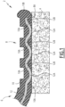
- a part 2 comprises a conductive layer 4 made of an electrically conductive textile and an electrical component 6 having a connection portion 8 welded to the conductive layer 4 so as to fix the electrical component 6 to the conductive layer 4 and to electrically connect the electrical component 6 to the conductive layer 4.
- the textile is made in such a way that the conductive layer 4 is capable of conducting electricity.
- the textile is formed from fibers including conductive fibers made from an electrically conductive material and thermoplastic fibers made from a thermoplastic material.
- the conductive fibers are carbon fibers and/or metal wires, in particular copper wires and/or aluminum wires.
- Carbon is an electrically conductive material.
- the conductive fibers are carbon fibers.
- thermoplastic fibers are polyolefin fibers, polypropylene fibers, polyester fibers, polyethylene terephthalate (PTFE) fibers, polycarbonate (PC) fibers, and/or polymethyl methacrylate (PMMA) fibers.
- PTFE polyethylene terephthalate
- PC polycarbonate
- PMMA polymethyl methacrylate
- thermoplastic fibers are polyolefin fibers, in particular polypropylene fibers.
- the textile is woven.
- the conductive fibers and the thermoplastic fibers are woven together to form a woven textile.
- the textile is non-woven.
- the conductive fibers and the thermoplastic fibers are agglomerated together without being woven.
- the nonwoven fabric is isotropic (the conductive fibers and the thermoplastic fibers have no preferred orientation) or anisotropic (the conductive fibers and the thermoplastic fibers have a preferred orientation).
- the nonwoven fabric is preferably consolidated, i.e. the conductive fibers and the thermoplastic fibers are bonded together.
- the consolidation of the conductive fibers and the thermoplastic fibers is carried out by needling, by pressurizing and/or by heating.
- the needling and pressurizing allows the fibers (i.e. the conductive fibers and the thermoplastic fibers) to be intimately intermingled.
- the heating allows the thermoplastic fibers to be welded together and with the conductive fibers.
- the electrical component 6 comprises a sheath 10 and an electrical conductor 12 extending inside the sheath 10.
- the sheath 10 provides electrical insulation of the electrical conductor 12 from the environment.
- the electrical conductor 12 is received inside the sheath 10 which surrounds the electrical conductor 12.
- the sheath 10 is electrically insulating and made of a thermoplastic material.
- the sheath 10 is made of polypropylene, polyvinyl chloride (PVC), poly(ethylene terephthalate) (PET), polycarbonate (PC) or polymethyl methacrylate (PMMA).
- PVC polyvinyl chloride
- PET poly(ethylene terephthalate)
- PC polycarbonate
- PMMA polymethyl methacrylate
- the sheath 10 is made of a thermoplastic material capable of welding with the thermoplastic material of the thermoplastic fibers of the conductive layer 4.
- the sheath 10 and the thermoplastic fibers of the conductive layer 4 are made of the same thermoplastic material.
- the electrical conductor 12 is for example made of a metallic material, for example copper.
- the electrical conductor 12 is for example a wire or an electrical track.
- the electrical component 6 is for example an insulated electrical wire comprising an electrical conductor 12 in the form of an electrical wire surrounded by the sheath 10.
- the electrical component 6 is for example a flexible electrical sheet comprising an electrical track, the sheath comprising two films, the track being interposed between the two films.
- connection portion 8 welded to the conductive layer 4, the sheath 10 is not removed in the connection portion 8 to perform welding.
- the sheath 10 surrounds the electrical conductor 12 in the connection portion 8.
- connection portion 8 is welded to the conductive layer 4 in such a way that, in the connection portion 8, the sheath 10 is welded to the conductive layer 4 and the electrical conductor 12 is in electrical contact with the conductive layer 4, in particular with the conductive fibers of the conductive layer 4.
- the welding of the sheath 10 to the conductive layer 4 makes it possible to ensure the mechanical connection of the connection portion 8 to the conductive layer 4.
- the contacting of the electrical conductor 12 with the conductive layer 4 makes it possible to ensure the electrical connection of the electrical component 6 to the conductive layer 4.
- the welding of the sheath 10 to the conductive layer 4 is carried out so as to weld the sheath 10 with the conductive layer 4, in particular with the thermoplastic fibers of the conductive layer 4.
- connection portion 8 the sheath 10 is welded to the conductive layer 4 so as to ensure the mechanical connection between the connection portion 8 and the conductive layer 4.
- connection portion 8 is in contact with the conductive layer 4 via a contact surface 8A of the connection portion 8.
- the electrical connection and the mechanical connection between the connection portion 8 and the conductive layer 4 are made via this contact surface 8A.
- connection portion 8 of the electrical component 6 welded to the conductive layer 4 the electrical conductor 12 has one or more contact portion(s) 12A, each contact portion 12A being in contact with the conductive layer 4, and the sheath 10 has one or more connection portion(s) 10A, each connection portion 10A being in contact with the conductive layer 4.
- Each contact portion 12A provides electrical contact between the electrical conductor 12 and the conductive layer 4.
- each contact portion 12A exits the sheath 10 at the interface between the sheath 10 and the conductive layer 4 to come into contact with the conductive layer 4.
- Each contact portion 12A is flush with the contact surface 8A.
- Each connecting portion 10A ensures the mechanical connection between the sheath 10 and the conductive layer 4.
- each connecting portion 10A is in contact with and welded to the conductive layer 4.
- the contact surface 8A of the connection portion 8 in contact with the conductive layer 4 is formed by the contact portion(s) 12A and the connection portion(s) 10A, which are located next to each other.
- the contact portion(s) 12A is (are) contiguous with the connecting portion(s) 10A.
- the contact portion(s) 12A and the connecting portion(s) 10A are located next to each other touching each other, i.e. without empty space between the contact portion(s) 12A and the connecting portion(s) 10A.
- Each contact portion 12A is contiguous with the connecting portion 10A or at least one of the connecting portions 10A.
- Each connecting portion 10A is contiguous with the contact portion 12A or at least one of the contact portions 12A.
- each contact portion 12A is surrounded by one or more connecting portions 10A contiguous to this contact portion 12A.
- connection portion 8 The electrical contact between the electrical conductor 12 and the conductive layer 4 and the mechanical connection between the sheath 10 and the conductive layer 4 are carried out jointly via the connection portion 8, in a contiguous manner.
- the electrical conductor 12 comprises several contact portions 12A spaced apart from each other.
- the contact portions 12A are distributed in a matrix manner.
- the electrical conductor 12 comprises at least one spaced portion 12B, each spaced portion 12B being spaced from the conductive layer 4.
- a connecting portion 10A of the sheath 10 is interposed between each spaced portion 12B of the conductor 12 and the conductive layer 4.
- At least one connecting portion 10A is still present between the electrical conductor 12 and the conductive layer 4.
- the contact portions 12A of the electrical conductor 12 are spaced apart from each other, the spaced portions 12B extending between the contact portions 12A.
- each contact portion 12A of the electrical conductor 12 forms a depression or hollow in the electrical conductor 12, with each spaced portion 12B forming a prominence or bump.
- the electrical conductor 12 thus has a bumpy shape in the connection portion 8.
- connection portion 8 welded to the conductive layer 4
- the electrical conductor 12 is deformed transversely to its extension line inside the sheath 10 so as to be in contact with the conductive layer 4.
- the connecting portion 8 is initially undeformed.
- connection portion 8 has a substantially circular cross-section before welding, the electrical conductor 12 being located in the center and being completely surrounded by the sheath 10 located at the periphery.
- connection portion 8 has the shape of a flat strip before welding, the electrical conductor 12 having the shape of a conductive track sandwiched between two films defining the sheath 10.
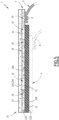
- the welding is carried out for example using a welding head 14 comprising a welding surface 16 intended to be applied to the connection portion 8 of the electrical component 6 so as to press it against the conductive layer 4, the welding head 14 optionally comprising one or more protrusion(s) 18 projecting from the welding surface 16.
- connection portion 8 is applied against the conductive layer 4 ( Figure 2 ).
- the connection portion 8 is in contact with the conductive layer 4 via the sheath 10.
- a portion of the sheath 10 is initially interposed between the electrical conductor 12 and the conductive layer 4.
- connection portion 8 When welding ( Figure 3 ), the welding head 14 is pressed against the connection portion 8.
- the welding surface 16 presses the connection portion 8 against the conductive layer 4, which presses the sheath 10 against the conductive layer 4 and ensures the welding of the sheath 10 on the conductive layer 4.
- the welding is carried out in such a way that the sheath 10 is welded to the conductive layer 4, the electrical conductor 12 being placed in electrical contact with the conductive layer 4.
- the welding is carried out in such a way that the electrical conductor 12 is deformed to form each contact portion 12A emerging from the sheath 10 to come into contact with the conductive layer 4.
- each protrusion 18 is locally introduced into the sheath 10 and locally pushes the electrical conductor 12 towards the conductive layer 4, such that the electrical conductor 12 is deformed by forming the contact portion(s) 12A, the electrical conductor 12 is brought into contact with the conductive layer 4.
- the electrical conductor 12 is locally pushed by each protrusion 18 inside the sheath 10 during welding, towards the conductive layer 4, so that it comes into contact with the conductive layer 4, and in particular with the conductive fibers of the textile forming the conductive layer 4.
- the electrical conductor 12 is then electrically connected to the conductive layer 4 ( Figure 3 ).
- the sheath 10 is crushed between the welding surface 16 and the conductive layer 4 and the material of the sheath 10 is partly pushed towards the periphery of the welding surface 16.
- the sheath 10 forms for example a peripheral bead 10B at the periphery of the connection portion 8 welded to the conductive layer 4, as illustrated on the right in the Figures 1 And 3 .
- connection portion 8 due to the welding, the material of the portion of the sheath 10 located between the electrical conductor 12 and the conductive layer 4 is at least partly driven away, so that the electrical conductor 12 comes into contact with the conductive layer 4.
- the material of the sheath 10 is expelled from the area located between each contact portion 12A, deformed during welding to be brought into contact with the conductive layer 4, and the conductive layer 4.
- each contact portion 12A exits the sheath 10 on the contact surface 8A of the connection portion 8 to come into contact with the conductive layer 4.
- the sheath 10 remains present around each contact portion 12A by forming one or more connecting portions 10A surrounding the contact portion 12A with which it(they) is(are) contiguous.
- one or more protrusion(s) 18 makes it possible to locally deform the electrical conductor 12 so that it comes into contact with the conductive layer 4, without completely removing the portion of the sheath 10 initially present between the electrical conductor 12 and the conductive layer 4.
- Each protrusion 18 makes it possible, for example, to form a contact portion 12A.
- Each contact portion 12A corresponds to a protrusion 18.
- Each protrusion 18 has geometric characteristics suitable for ensuring contact between the electrical conductor 12 and the conductive layer 4 during welding.
- each protrusion 18 has a height (taken along the normal N to the welding surface 16) greater than half the thickness of the connection portion 8 before welding and/or less than four times the thickness of the connection portion 8 before welding.
- protrusions 18 are preferably distributed on the welding surface 16 so as to promote contact between the electrical conductor 12 and the conductive layer 4 during welding, while achieving satisfactory welding of the sheath 10 on the conductive layer 4.
- each protrusion 18 has a transverse dimension and is spaced from each other adjacent protrusion 18 by a spacing distance.
- each protrusion 18 along at least one transverse direction is substantially equal to the spacing between the protrusions along said transverse dimension.
- the protrusions 18 are distributed over the welding surface 16 while being aligned in a first transverse direction T1 and in a second transverse direction T2.
- the transverse dimension D1 of each protrusion 18 along the first transverse direction T1, the spacing E1 between the protrusions 18 along the first transverse direction T1, the transverse dimension D2 of each protrusion 18 along the second transverse direction T2 and the spacing E2 between the protrusions 18 along the second transverse direction T2 are substantially equal.
- the transverse dimension D1 of each protrusion 18 along the first transverse direction T1 and/or the transverse dimension D2 of each protrusion 18 along the second transverse direction T2 is (are) greater than one twentieth of the thickness of the connection portion 8 before welding and/or less than the thickness of the connection portion 8 before welding.
- the spacing E1 between the adjacent protrusions 18 along the first transverse direction T1 and/or the spacing E2 between the adjacent protrusions 18 along the second transverse direction T2 is (are) greater than one twentieth of the thickness of the connection portion 8 before welding and/or less than the thickness of the connection portion 8 before welding.
- the thickness of the connection portion 8 before welding corresponds to the diameter of the electrical component 6.
- connection portion 8 is welded to the conductive layer 4, for example by ultrasonic welding.
- the welding head 14 is an ultrasonic welding head or “sonotrode”.
- the welding head 14 is connected to an ultrasonic generator (not shown) for the generation of ultrasound in the welding head 14 applied against the connection portion 8, itself applied to the conductive layer 4.
- a method of manufacturing the part 2 comprises providing a conductive layer 4 made of an electrically conductive textile, applying the portion of connection 8 of the electrical component 6 against the conductive layer 4, and welding the connection portion 8 of the electrical component 6 onto the conductive layer 4, for example by ultrasonic welding, in particular using a welding head 14 as described above.
- the conductive layer 4, on which the connection portion 8 of the electrical component 6 is fixed and electrically connected, is, for example, fixed to a support.
- the support is made of a composite material comprising reinforcing fibers, preferably natural reinforcing fibers, in particular flax fibers, hemp fibers, kenaf fibers and/or wood fibers, embedded in a matrix, preferably a thermoplastic matrix, in particular a polypropylene matrix.
- reinforcing fibers preferably natural reinforcing fibers, in particular flax fibers, hemp fibers, kenaf fibers and/or wood fibers, embedded in a matrix, preferably a thermoplastic matrix, in particular a polypropylene matrix.
- a material comprising natural fibres embedded in a polypropylene matrix is also known by the acronym NFPP for "Natural Fibre PolyPropylene" in English.
- the conductive layer 4 can be easily assembled with such a support due to the presence of thermoplastic fibers in the textile forming the conductive layer 4, which can bond with the thermoplastic matrix of the support, for example by pressing, optionally with heating.
- the part 2 may comprise a conductive layer 4 or several conductive layers 4. Each conductive layer 4 may be associated with an electrical component 6 or several electrical components 6, each electrical component 6 having a connection portion 8 welded to the associated conductive layer 4.
- the part 2 comprises one or more conductive layers 4, each conductive layer 4 being associated with at least one electrical component 6 having a connection portion 8 welded onto this conductive layer 4.
- the part 2 comprises a laminate 20 formed of several superimposed layers including the conductive layer 4 and, in addition, a support layer 22.
- the laminate 20 has a front face 20A intended to be visible and a rear face 20B opposite the front face 20A.
- the support layer 22 defines a support.
- the support layer 22 gives the laminate 4 its shape, as well as its mechanical characteristics, in particular its rigidity.
- the support layer 22 is for example made of a plastic material or a composite material.
- the support layer 22 is made of a composite material comprising natural fibers embedded in a matrix of material plastic, in particular a polypropylene matrix.
- Natural fibres include, for example, flax fibres, hemp fibres, kenaf fibres and/or wood fibres.
- the support layer 22 has, for example, a planar shape or a three-dimensional shape with raised areas.
- the support layer 22 comprises, for example, an area projecting relative to the remainder of the support layer 22 to form an armrest.
- the support layer 22 is, for example, formed by injection molding in a molding cavity having the desired shape of the support layer.
- the support layer 22 has a front face 22A facing the front face 20A of the laminate 20, and a rear face 22B opposite its front face 22A.
- the laminate comprises a decorative layer 24.
- the decorative layer 24 defines, for example, the front face 20A of the laminate 20, intended to be visible.
- the decorative layer 24 covers at least part of the front face 22A of the support layer 22. In an exemplary embodiment, the decorative layer 24 completely covers the front face 22A of the support layer 22.
- the decorative layer 24 comprises a front face 24A facing away from the support layer 22 and a rear face 24B facing towards the support layer 22.
- the decorative layer 24 gives its appearance and/or feel to the part 2.
- the decorative layer 24 is made of a material having a particular appearance and/or feel that it is desired to give to the motor vehicle part 2.
- the decorative layer 24 is for example made of textile material, plastic material, wood material, leather, imitation leather or other.
- the decorative layer 24 is shaped to the support layer 22, that is to say that it substantially matches the shape of the front face 22A of the support layer 22, in the area of the front face 22A of the support layer 22 that the decorative layer 24 covers.
- the front face 24A of the decorative layer 24 may include indications intended for a user, for example to indicate the presence of a functional zone, as will be described later.
- the decorative layer 24 is translucent, at least in certain translucent areas allowing light to pass from the rear face 24B to the front face 24A of the decorative layer 24. This makes it possible to backlight these areas in order to inform a user of the presence of a functional area for example.
- the conductive layer 4 makes it possible to create functional electrical circuits integrated into the laminate 20.
- the conductive layer 4 comprises at least one pattern 26 formed by at least one conductive zone 28 formed by the conductive layer 4. and at least one non-conductive area 30, each conductive area 28 of the pattern 26 being a solid area of the conductive layer 4 and each non-conductive area 30 of the pattern 26 being formed by a through opening 32 formed through the conductive layer 4.
- Each pattern 26 has shapes adapted to define a functional electrical circuit performing a particular function when each conductive zone 28 of the pattern 26 is supplied with electricity via an electrical component 6 welded to the conductive layer 4.
- the function performed by the functional electrical circuit is a function of interaction with a user on the front face 20A of the laminate 20.
- the functional electrical circuit is configured to provide a human-machine interface, a user being able to interact with the front face 20A of the laminate 20 to activate, control and/or influence a function performed by a machine connected to the conductive layer 4 via an electrical component 6.
- the functional electrical circuit is for example a resistive circuit or a capacitive circuit capable of detecting the contact and/or proximity of a user's finger with the front face 20A of the laminate 20 at the level of the functional electrical circuit formed by the pattern 18.
- each pattern 26 defines for example a touch button, a touch slider or a touch surface, in particular a multi-point touch surface defining several interaction points.
- the functional electrical circuit is for example a heating resistive circuit. This makes it possible to produce a heating motor vehicle part 2, i.e. integrating a heating function.
- Each pattern 26 is connected to an electrical source via an electrical component 6 welded onto the conductive layer 4 for its electricity supply.
- a conductive layer 4 is provided with a pattern 26 or several patterns 26.
- An electrical component 6 makes it possible to connect a pattern 26 or several patterns 26 of a conductive layer 4 to an electrical source.
- the laminate 20 comprises one or more conductive layers 4, each conductive layer 4 being associated with at least one electrical component 6 having a connection portion 8 welded to this conductive layer 4.
- each conductive layer 4 comprises at least one pattern 26 defining a functional electrical circuit.
- the laminate 20 comprises a conductive layer 4 arranged on the front face of the layer of support 22, and in particular, where appropriate, a conductive layer 4 interposed between the support layer 22 and the decorative layer 24.
- the laminate comprises a conductive layer 4 covering the rear face 22B of the support layer 22.
- the laminate 20 comprises for example a single conductive layer 4 arranged on the front face 22A of the support layer 22, a single conductive layer 4 arranged on the rear face 22B of the support layer 22, or two conductive layers 4.
- the laminate 20 comprises two conductive layers 4, and preferably, these conductive layers 4 are located on either side of the support layer 22, which is sandwiched between the two conductive layers 4. Each conductive layer 4 is preferably in contact with a respective face of the support layer 22.
- An exemplary embodiment with two conductive layers 4 is particularly suitable for producing a capacitive sensor using two functional electrical circuits, each functional electrical circuit being formed in a respective conductive layer 4 among the two conductive layers 4, the two electrical circuits being superimposed.
- a capacitive sensor makes it possible to detect a contact and/or the proximity of a user's finger.
- Each conductive layer 4 is fixed to the support layer 20, for example by applying the conductive layer 4 against the support layer 20 with pressure and/or heating.
- the support layer 22 is made of a thermoplastic material or comprises a thermoplastic matrix, this makes it possible to obtain adhesion between the thermoplastic matrix of the support layer 22 and the thermoplastic fibers of the conductive layer 4.
- Adhesion is particularly good when the thermoplastic fibres and the thermoplastic material or thermoplastic matrix are made of the same material, for example polypropylene.
- each conductive layer 4 is fixed to the support layer 22 by gluing, using a layer of glue interposed between the conductive layer 4 and the support layer 22.
- Each conductive layer 4 made of a textile formed of conductive fibers and thermoplastic fibers and applied against the support layer 22 to obtain the laminate 20, reinforces the support layer 22 and thus defines a reinforcement layer.
- a method of manufacturing the part 2 comprises providing a support layer 22, providing at least one conductive layer 4, and assembling the support layer 22 with each conductive layer 4 to form a laminate 20, for example by pressurizing and/or heating.
- the manufacturing method comprises the production of each pattern 26 in each conductive layer 4, and providing one or more through opening(s) 32 through this conductive layer 4.
- Each through opening 32 formed in a conductive layer 4 is hollowed out over the entire thickness of this conductive layer 4, for example by laser machining, by mechanical machining and/or by chemical attachment.
- each pattern 26 in each conductive layer 4 is carried out after application and fixing of the conductive layer 4 on the support layer 22.
- the manufacturing method comprises, where appropriate, the assembly of the decorative layer 24, for example on the front face 22A of the support layer 22 or on a conductive layer 4 covering the front face 22A of the support layer 22.
- the fixing is carried out for example by gluing.
- the invention is not limited to the exemplary embodiments and variants described above.
- the electrical conductor 12 is in contact with the conductive layer 4, the sheath 10 extending on the side of the electrical conductor 12 opposite the conductive layer 4 and covering the electrical conductor 12.
- the part of the electrical conductor 12 opposite the conductive layer 4 in the electrical contact portions 12A is not covered with sheath 10.
Landscapes
- Engineering & Computer Science (AREA)
- Mechanical Engineering (AREA)
- Textile Engineering (AREA)
- Manufacturing & Machinery (AREA)
- Laminated Bodies (AREA)
Claims (15)
- Teil, zum Beispiel Verkleidungsteil für ein Kraftfahrzeug, mit mindestens einer leitfähigen Schicht (4) aus einem elektrisch leitfähigen Textil, wobei das Textil leitfähige Fasern aus einem elektrisch leitfähigen Material und thermoplastische Fasern aus einem thermoplastischen Material umfasst, und mindestens eine elektrische Komponente (6), die mit jeder leitfähigen Schicht (4) verbunden ist, wobei jede elektrische Komponente (6) eine Hülle (10) und einen elektrischen Leiter (12) umfasst, der sich innerhalb der Hülle (10) erstreckt, wobei die Hülle (10) aus einem elektrisch isolierenden thermoplastischen Material hergestellt ist, jede elektrische Komponente (6) einen Verbindungsabschnitt (8) umfasst, der mechanisch mit der zugehörigen leitenden Schicht (4) verbunden ist, indem die Hülle (10) auf die leitende Schicht (4) gelötet wird, wobei in dem Verbindungsabschnitt (8), der elektrische Leiter (12) durch einen oder mehrere Kontaktabschnitte (12A) des elektrischen Leiters (12) in elektrischem Kontakt mit der leitfähigen Schicht (4) steht und die Hülle (10) durch einen oder mehrere Verbindungsabschnitte (10A) der Hülle (10) mechanisch mit der leitenden Schicht (4) verbunden ist, wobei der eine oder die mehreren Kontaktabschnitte (12A) an den einen oder die mehreren Verbindungsabschnitte (10A) angrenzt bzw. angrenzen.
- Teil nach Anspruch 1, das mehrere Kontaktabschnitte (12A) umfasst, die durch einen oder mehrere Verbindungsabschnitte (1 0A) voneinander getrennt sind.
- Teil nach Anspruch 1 oder 2, wobei in dem Verbindungsabschnitt (8) der elektrische Leiter (12) mindestens einen beabstandeten Abschnitt (12B) umfasst, der von der leitenden Schicht (4) beabstandet ist, wobei ein Verbindungsabschnitt (10A) der Hülle (10) zwischen jedem beabstandeten Abschnitt (12B) des elektrischen Leiters (12) und der leitfähigen Schicht (4) angeordnet ist.
- Teil nach einem der vorstehenden Ansprüche, wobei die elektrische Komponente (6) ein elektrischer Draht oder eine elektrische Matte ist.
- Teil nach einem der vorstehenden Ansprüche, wobei die leitenden Fasern Kohlenstofffasern und/oder Metallfäden sind und/oder die thermoplastischen Fasern Polypropylenfasern, Polyolefinfasern, Polypropylenfasern, Polyesterfasern, Polyethylenterephthalatfasern (PTFE), Polycarbonatfasern (PC) und/oder Polymethylmethacrylatfasern (PMMA) sind.
- Teil nach einem der vorstehenden Ansprüche, umfassend ein Laminat (20), das aus einer Trägerschicht (22) und jeder leitfähigen Schicht (4) gebildet wird.
- Teil nach Anspruch 6, wobei die Stützschicht (22) aus einem Verbundmaterial hergestellt ist, das in eine Matrix eingebettete Verstärkungsfasern umfasst, wobei die Matrix aus einem thermoplastischen Material hergestellt ist.
- Teil nach Anspruch 7, wobei die Verstärkungsfasern Naturfasern sind und/oder die Matrix des Trägers aus Polypropylen hergestellt ist.
- Teil nach einem der vorstehenden Ansprüche, wobei jede leitfähigen Schicht (4) mindestens ein Muster (26) umfasst, das durch mindestens einen leitenden Bereich (28) der leitenden Schicht und mindestens einen nichtleitenden Bereich (30) gebildet wird, der durch eine Durchgangsöffnung (32) definiert ist, die in der leitfähigen Schicht (4) ausgebildet ist, wobei das Muster (26) einen funktionalen elektrischen Schaltkreis definiert, der für die Erfassung einer Interaktion eines Benutzers mit dem Teil (2) an dem Muster (26) konfiguriert ist.
- Teil nach einem der vorstehenden Ansprüche, wobei das Textil ein nicht gewebtes Textil ist.
- Herstellungsverfahren eines Teils, zum Beispiel eines Verkleidungsteils eines Kraftfahrzeugs, wobei das Herstellungsverfahren die Bereitstellung mindestens einer leitfähigen Schicht (4), die aus einem elektrisch leitenden Textil hergestellt ist, das leitende Fasern, die aus einem elektrisch leitenden Material hergestellt sind, und thermoplastische Fasern, die aus einem thermoplastischen Material hergestellt sind, umfasst, die Bereitstellung mindestens einer elektrischen Komponente (6), die mit jeder leitfähigen Schicht (4) verbunden ist, umfasst, wobei jede elektrische Komponente (6) eine Hülle (10) und einen elektrischen Leiter (12) umfasst, der sich innerhalb der Hülle (10) erstreckt, wobei die Hülle (10) aus einem elektrisch isolierenden thermoplastischen Material hergestellt ist, und Anschweißen eines Verbindungsabschnitts (8) jeder elektrischen Komponente (6) an die zugehörige leitfähige Schicht (4), so dass die Hülle (10) an die leitfähige Schicht (4) geschweißt wird und das leitende Element in elektrischem Kontakt mit der leitfähigen Schicht (4) steht.
- Herstellungsverfahren nach Anspruch 11, bei dem das Schweißen unter Verwendung eines Schweißkopfes (14) durchgeführt wird, der eine Schweißfläche (16) aufweist, die dazu bestimmt ist, zum Schweißen der Hülle gegen den Anschlussabschnitt (8) eines elektrischen Bauteils (6) gedrückt zu werden (10) mit der zugeordneten leitfähigen Schicht (4), wobei der Schweißkopf (14) einen oder mehrere Vorsprung(e) (18) umfasst, die von der Schweißfläche (16) abstehen, um den elektrischen Leiter (12) zu drücken, der sich im Inneren erstreckt Mantel (10) im Verbindungsabschnitt (8), in elektrischen Kontakt mit der leitenden Schicht (4), wenn der Mantel (10) auf der leitenden Schicht (4) verschweißt wird.
- Herstellungsverfahren nach Anspruch 11 oder 12, bei dem das Schweißen mit Ultraschall durchgeführt wird.
- Herstellungsverfahren nach einem der Ansprüche 11 bis 13, wobei das Herstellungsverfahren in mindestens einer oder jeder leitenden Schicht die Herstellung mindestens eines Musters umfasst, das durch mindestens einen leitenden Bereich der leitfähigen Schicht und mindestens einen nichtleitenden Bereich gebildet wird, der durch eine Durchgangsöffnung in der leitfähigen Schicht definiert ist, wobei das Muster einen funktionalen elektrischen Schaltkreis definiert, der so konfiguriert ist, dass er eine Interaktion eines Benutzers mit dem Teil an dem Muster erfasst.
- Herstellungsverfahren nach einem der Ansprüche 11 bis 14, wobei das Herstellungsverfahren die Bildung eines Laminats umfasst, das in Überlagerung eine Trägerschicht und jede leitfähige Schicht umfasst, wobei die Trägerschicht beispielsweise aus einem Verbundmaterial hergestellt ist, das in eine Matrix eingebettete Verstärkungsfasern umfasst, wobei die Matrix aus einem thermoplastischen Material hergestellt ist.
Applications Claiming Priority (1)
| Application Number | Priority Date | Filing Date | Title |
|---|---|---|---|
| FR2012684A FR3117072B1 (fr) | 2020-12-04 | 2020-12-04 | Pièce comprenant une couche conductrice et procédé de fabrication d’une telle pièce |
Publications (2)
| Publication Number | Publication Date |
|---|---|
| EP4008591A1 EP4008591A1 (de) | 2022-06-08 |
| EP4008591B1 true EP4008591B1 (de) | 2024-09-04 |
Family
ID=74669026
Family Applications (1)
| Application Number | Title | Priority Date | Filing Date |
|---|---|---|---|
| EP21212171.9A Active EP4008591B1 (de) | 2020-12-04 | 2021-12-03 | Bauteil mit einer leiterschicht und verfahren zur herstellung eines solchen bauteils |
Country Status (4)
| Country | Link |
|---|---|
| EP (1) | EP4008591B1 (de) |
| CN (1) | CN114596979A (de) |
| ES (1) | ES2992166T3 (de) |
| FR (1) | FR3117072B1 (de) |
Family Cites Families (2)
| Publication number | Priority date | Publication date | Assignee | Title |
|---|---|---|---|---|
| EP2071906A1 (de) * | 2007-12-13 | 2009-06-17 | Gemplus | Verfahren zur Herstellung einer Vorrichtung, die mindestens zwei verschiedene Komponenten umfasst, die durch Verbindungsdrähte miteinander verbunden sind, und so erhaltene Vorrichtung |
| FR3048151B1 (fr) * | 2016-02-19 | 2018-02-23 | Gerflor | Structure multicouche pour la realisation d'un revetement de sol ou de mur chauffant |
-
2020
- 2020-12-04 FR FR2012684A patent/FR3117072B1/fr active Active
-
2021
- 2021-12-03 CN CN202111467258.9A patent/CN114596979A/zh active Pending
- 2021-12-03 EP EP21212171.9A patent/EP4008591B1/de active Active
- 2021-12-03 ES ES21212171T patent/ES2992166T3/es active Active
Also Published As
| Publication number | Publication date |
|---|---|
| FR3117072B1 (fr) | 2024-04-26 |
| ES2992166T3 (es) | 2024-12-09 |
| EP4008591A1 (de) | 2022-06-08 |
| CN114596979A (zh) | 2022-06-07 |
| FR3117072A1 (fr) | 2022-06-10 |
Similar Documents
| Publication | Publication Date | Title |
|---|---|---|
| EP3051698B1 (de) | Bedientafel für fahrzeug, und verfahren zur herstellung einer solchen bedientafel | |
| EP1438172B1 (de) | Verfahren zur herstellung einer kunststoffscheibe mit elektrischer leitungsstruktur und kunststoffscheibe mit eingebetteten drähten | |
| EP1062635B1 (de) | Verfahren zur herstellung von kontaktlosen karten | |
| FR3116473A1 (fr) | Elément de garnissage comprenant un élément de chauffage et un capteur de proximité | |
| EP1442424B1 (de) | Verfahren zur herstellung einer kontaktlosen chipkarte oder einer hybriden chipkarte mit und ohne kontakten mit verbesserter flachheit | |
| FR3116474A1 (fr) | Elément de garnissage comprenant un élément de chauffage en un matériau carbone | |
| EP2691253B1 (de) | Steuerungs- und anzeigemodul für kraftfahrzeuge | |
| FR3121404A1 (fr) | Elément de garnissage rétroéclairé comprenant une couche fonctionnelle en matériau carbone | |
| CN100518416C (zh) | 用于机动车方向盘的可加热胶合构件及其生产方法 | |
| EP3448824B1 (de) | Verbundglas mit einem satz von dioden | |
| FR3116489A1 (fr) | Elément de garnissage comprenant une couche fonctionnelle en matériau carbone | |
| KR20200026973A (ko) | 입력 장치의 제조 방법 및 입력 장치 | |
| CN112873464A (zh) | 木质装饰板及其制造方法、成形品及其制造方法 | |
| FR3043952A1 (fr) | Panneau de commande a capteur piezoelectrique souple pour un vehicule | |
| EP4008591B1 (de) | Bauteil mit einer leiterschicht und verfahren zur herstellung eines solchen bauteils | |
| EP1160937A1 (de) | Elektrisches lötbares Verbindungselement mit Lötstelle | |
| FR3116488A1 (fr) | Elément de garnissage comprenant une couche de décor en matériau carbone | |
| FR2871119A1 (fr) | Element moule en mousse chauffe electriquement, essentiellement element d'assise equipant un interieur de vehicule ainsi que le procede de realisation correspondant | |
| EP2511809A1 (de) | Verfahren zur Herstellung eines berührungsempfindlichen kapazitiven Sensors | |
| FR3116469A1 (fr) | Procédé de réalisation d’un élément de garnissage comprenant une couche de décor en matériau carbone | |
| FR2923177A1 (fr) | Procede d'assemblage d'une piece composite | |
| FR3117073A1 (fr) | Elément de garnissage comprenant un élément fonctionnel en matériau composite pyrolysé | |
| FR3121640A1 (fr) | Panneau de commande pour véhicule et procédé de réalisation | |
| FR3134070A1 (fr) | Elément de garnissage comprenant un élément de chauffage discret en matériau carbone | |
| WO2023237655A1 (fr) | Préforme pour fabriquer une pièce en matériau composite comprenant un capteur capacitif, procédé de fabrication d'une telle préforme, pièce en matériau composite et procédé de fabrication associés |
Legal Events
| Date | Code | Title | Description |
|---|---|---|---|
| PUAI | Public reference made under article 153(3) epc to a published international application that has entered the european phase |
Free format text: ORIGINAL CODE: 0009012 |
|
| STAA | Information on the status of an ep patent application or granted ep patent |
Free format text: STATUS: THE APPLICATION HAS BEEN PUBLISHED |
|
| AK | Designated contracting states |
Kind code of ref document: A1 Designated state(s): AL AT BE BG CH CY CZ DE DK EE ES FI FR GB GR HR HU IE IS IT LI LT LU LV MC MK MT NL NO PL PT RO RS SE SI SK SM TR |
|
| STAA | Information on the status of an ep patent application or granted ep patent |
Free format text: STATUS: REQUEST FOR EXAMINATION WAS MADE |
|
| 17P | Request for examination filed |
Effective date: 20221115 |
|
| RBV | Designated contracting states (corrected) |
Designated state(s): AL AT BE BG CH CY CZ DE DK EE ES FI FR GB GR HR HU IE IS IT LI LT LU LV MC MK MT NL NO PL PT RO RS SE SI SK SM TR |
|
| GRAP | Despatch of communication of intention to grant a patent |
Free format text: ORIGINAL CODE: EPIDOSNIGR1 |
|
| STAA | Information on the status of an ep patent application or granted ep patent |
Free format text: STATUS: GRANT OF PATENT IS INTENDED |
|
| INTG | Intention to grant announced |
Effective date: 20240423 |
|
| GRAS | Grant fee paid |
Free format text: ORIGINAL CODE: EPIDOSNIGR3 |
|
| GRAA | (expected) grant |
Free format text: ORIGINAL CODE: 0009210 |
|
| STAA | Information on the status of an ep patent application or granted ep patent |
Free format text: STATUS: THE PATENT HAS BEEN GRANTED |
|
| AK | Designated contracting states |
Kind code of ref document: B1 Designated state(s): AL AT BE BG CH CY CZ DE DK EE ES FI FR GB GR HR HU IE IS IT LI LT LU LV MC MK MT NL NO PL PT RO RS SE SI SK SM TR |
|
| REG | Reference to a national code |
Ref country code: GB Ref legal event code: FG4D Free format text: NOT ENGLISH |
|
| REG | Reference to a national code |
Ref country code: CH Ref legal event code: EP |
|
| REG | Reference to a national code |
Ref country code: IE Ref legal event code: FG4D Free format text: LANGUAGE OF EP DOCUMENT: FRENCH |
|
| REG | Reference to a national code |
Ref country code: DE Ref legal event code: R096 Ref document number: 602021018250 Country of ref document: DE |
|
| REG | Reference to a national code |
Ref country code: ES Ref legal event code: FG2A Ref document number: 2992166 Country of ref document: ES Kind code of ref document: T3 Effective date: 20241209 |
|
| REG | Reference to a national code |
Ref country code: LT Ref legal event code: MG9D |
|
| REG | Reference to a national code |
Ref country code: NL Ref legal event code: MP Effective date: 20240904 |
|
| PG25 | Lapsed in a contracting state [announced via postgrant information from national office to epo] |
Ref country code: NO Free format text: LAPSE BECAUSE OF FAILURE TO SUBMIT A TRANSLATION OF THE DESCRIPTION OR TO PAY THE FEE WITHIN THE PRESCRIBED TIME-LIMIT Effective date: 20241204 |
|
| PG25 | Lapsed in a contracting state [announced via postgrant information from national office to epo] |
Ref country code: GR Free format text: LAPSE BECAUSE OF FAILURE TO SUBMIT A TRANSLATION OF THE DESCRIPTION OR TO PAY THE FEE WITHIN THE PRESCRIBED TIME-LIMIT Effective date: 20241205 Ref country code: PL Free format text: LAPSE BECAUSE OF FAILURE TO SUBMIT A TRANSLATION OF THE DESCRIPTION OR TO PAY THE FEE WITHIN THE PRESCRIBED TIME-LIMIT Effective date: 20240904 Ref country code: FI Free format text: LAPSE BECAUSE OF FAILURE TO SUBMIT A TRANSLATION OF THE DESCRIPTION OR TO PAY THE FEE WITHIN THE PRESCRIBED TIME-LIMIT Effective date: 20240904 |
|
| PG25 | Lapsed in a contracting state [announced via postgrant information from national office to epo] |
Ref country code: BG Free format text: LAPSE BECAUSE OF FAILURE TO SUBMIT A TRANSLATION OF THE DESCRIPTION OR TO PAY THE FEE WITHIN THE PRESCRIBED TIME-LIMIT Effective date: 20240904 |
|
| PG25 | Lapsed in a contracting state [announced via postgrant information from national office to epo] |
Ref country code: LV Free format text: LAPSE BECAUSE OF FAILURE TO SUBMIT A TRANSLATION OF THE DESCRIPTION OR TO PAY THE FEE WITHIN THE PRESCRIBED TIME-LIMIT Effective date: 20240904 |
|
| PG25 | Lapsed in a contracting state [announced via postgrant information from national office to epo] |
Ref country code: HR Free format text: LAPSE BECAUSE OF FAILURE TO SUBMIT A TRANSLATION OF THE DESCRIPTION OR TO PAY THE FEE WITHIN THE PRESCRIBED TIME-LIMIT Effective date: 20240904 |
|
| PG25 | Lapsed in a contracting state [announced via postgrant information from national office to epo] |
Ref country code: RS Free format text: LAPSE BECAUSE OF FAILURE TO SUBMIT A TRANSLATION OF THE DESCRIPTION OR TO PAY THE FEE WITHIN THE PRESCRIBED TIME-LIMIT Effective date: 20241204 |
|
| PG25 | Lapsed in a contracting state [announced via postgrant information from national office to epo] |
Ref country code: RS Free format text: LAPSE BECAUSE OF FAILURE TO SUBMIT A TRANSLATION OF THE DESCRIPTION OR TO PAY THE FEE WITHIN THE PRESCRIBED TIME-LIMIT Effective date: 20241204 Ref country code: PL Free format text: LAPSE BECAUSE OF FAILURE TO SUBMIT A TRANSLATION OF THE DESCRIPTION OR TO PAY THE FEE WITHIN THE PRESCRIBED TIME-LIMIT Effective date: 20240904 Ref country code: NO Free format text: LAPSE BECAUSE OF FAILURE TO SUBMIT A TRANSLATION OF THE DESCRIPTION OR TO PAY THE FEE WITHIN THE PRESCRIBED TIME-LIMIT Effective date: 20241204 Ref country code: LV Free format text: LAPSE BECAUSE OF FAILURE TO SUBMIT A TRANSLATION OF THE DESCRIPTION OR TO PAY THE FEE WITHIN THE PRESCRIBED TIME-LIMIT Effective date: 20240904 Ref country code: HR Free format text: LAPSE BECAUSE OF FAILURE TO SUBMIT A TRANSLATION OF THE DESCRIPTION OR TO PAY THE FEE WITHIN THE PRESCRIBED TIME-LIMIT Effective date: 20240904 Ref country code: GR Free format text: LAPSE BECAUSE OF FAILURE TO SUBMIT A TRANSLATION OF THE DESCRIPTION OR TO PAY THE FEE WITHIN THE PRESCRIBED TIME-LIMIT Effective date: 20241205 Ref country code: FI Free format text: LAPSE BECAUSE OF FAILURE TO SUBMIT A TRANSLATION OF THE DESCRIPTION OR TO PAY THE FEE WITHIN THE PRESCRIBED TIME-LIMIT Effective date: 20240904 Ref country code: BG Free format text: LAPSE BECAUSE OF FAILURE TO SUBMIT A TRANSLATION OF THE DESCRIPTION OR TO PAY THE FEE WITHIN THE PRESCRIBED TIME-LIMIT Effective date: 20240904 |
|
| REG | Reference to a national code |
Ref country code: AT Ref legal event code: MK05 Ref document number: 1720060 Country of ref document: AT Kind code of ref document: T Effective date: 20240904 |
|
| PG25 | Lapsed in a contracting state [announced via postgrant information from national office to epo] |
Ref country code: NL Free format text: LAPSE BECAUSE OF FAILURE TO SUBMIT A TRANSLATION OF THE DESCRIPTION OR TO PAY THE FEE WITHIN THE PRESCRIBED TIME-LIMIT Effective date: 20240904 |
|
| PG25 | Lapsed in a contracting state [announced via postgrant information from national office to epo] |
Ref country code: PT Free format text: LAPSE BECAUSE OF FAILURE TO SUBMIT A TRANSLATION OF THE DESCRIPTION OR TO PAY THE FEE WITHIN THE PRESCRIBED TIME-LIMIT Effective date: 20250106 Ref country code: IS Free format text: LAPSE BECAUSE OF FAILURE TO SUBMIT A TRANSLATION OF THE DESCRIPTION OR TO PAY THE FEE WITHIN THE PRESCRIBED TIME-LIMIT Effective date: 20250104 |
|
| PG25 | Lapsed in a contracting state [announced via postgrant information from national office to epo] |
Ref country code: SM Free format text: LAPSE BECAUSE OF FAILURE TO SUBMIT A TRANSLATION OF THE DESCRIPTION OR TO PAY THE FEE WITHIN THE PRESCRIBED TIME-LIMIT Effective date: 20240904 Ref country code: RO Free format text: LAPSE BECAUSE OF FAILURE TO SUBMIT A TRANSLATION OF THE DESCRIPTION OR TO PAY THE FEE WITHIN THE PRESCRIBED TIME-LIMIT Effective date: 20240904 |
|
| PGFP | Annual fee paid to national office [announced via postgrant information from national office to epo] |
Ref country code: ES Payment date: 20250102 Year of fee payment: 4 |
|
| PG25 | Lapsed in a contracting state [announced via postgrant information from national office to epo] |
Ref country code: EE Free format text: LAPSE BECAUSE OF FAILURE TO SUBMIT A TRANSLATION OF THE DESCRIPTION OR TO PAY THE FEE WITHIN THE PRESCRIBED TIME-LIMIT Effective date: 20240904 Ref country code: AT Free format text: LAPSE BECAUSE OF FAILURE TO SUBMIT A TRANSLATION OF THE DESCRIPTION OR TO PAY THE FEE WITHIN THE PRESCRIBED TIME-LIMIT Effective date: 20240904 |
|
| PG25 | Lapsed in a contracting state [announced via postgrant information from national office to epo] |
Ref country code: CZ Free format text: LAPSE BECAUSE OF FAILURE TO SUBMIT A TRANSLATION OF THE DESCRIPTION OR TO PAY THE FEE WITHIN THE PRESCRIBED TIME-LIMIT Effective date: 20240904 |
|
| PG25 | Lapsed in a contracting state [announced via postgrant information from national office to epo] |
Ref country code: SK Free format text: LAPSE BECAUSE OF FAILURE TO SUBMIT A TRANSLATION OF THE DESCRIPTION OR TO PAY THE FEE WITHIN THE PRESCRIBED TIME-LIMIT Effective date: 20240904 Ref country code: IT Free format text: LAPSE BECAUSE OF FAILURE TO SUBMIT A TRANSLATION OF THE DESCRIPTION OR TO PAY THE FEE WITHIN THE PRESCRIBED TIME-LIMIT Effective date: 20240904 |
|
| REG | Reference to a national code |
Ref country code: DE Ref legal event code: R097 Ref document number: 602021018250 Country of ref document: DE |
|
| PG25 | Lapsed in a contracting state [announced via postgrant information from national office to epo] |
Ref country code: MC Free format text: LAPSE BECAUSE OF FAILURE TO SUBMIT A TRANSLATION OF THE DESCRIPTION OR TO PAY THE FEE WITHIN THE PRESCRIBED TIME-LIMIT Effective date: 20240904 |
|
| PG25 | Lapsed in a contracting state [announced via postgrant information from national office to epo] |
Ref country code: DK Free format text: LAPSE BECAUSE OF FAILURE TO SUBMIT A TRANSLATION OF THE DESCRIPTION OR TO PAY THE FEE WITHIN THE PRESCRIBED TIME-LIMIT Effective date: 20240904 |
|
| PLBE | No opposition filed within time limit |
Free format text: ORIGINAL CODE: 0009261 |
|
| STAA | Information on the status of an ep patent application or granted ep patent |
Free format text: STATUS: NO OPPOSITION FILED WITHIN TIME LIMIT |
|
| REG | Reference to a national code |
Ref country code: CH Ref legal event code: PL |
|
| 26N | No opposition filed |
Effective date: 20250605 |
|
| PG25 | Lapsed in a contracting state [announced via postgrant information from national office to epo] |
Ref country code: LU Free format text: LAPSE BECAUSE OF NON-PAYMENT OF DUE FEES Effective date: 20241203 |
|
| PG25 | Lapsed in a contracting state [announced via postgrant information from national office to epo] |
Ref country code: SE Free format text: LAPSE BECAUSE OF FAILURE TO SUBMIT A TRANSLATION OF THE DESCRIPTION OR TO PAY THE FEE WITHIN THE PRESCRIBED TIME-LIMIT Effective date: 20240904 |
|
| PG25 | Lapsed in a contracting state [announced via postgrant information from national office to epo] |
Ref country code: CH Free format text: LAPSE BECAUSE OF NON-PAYMENT OF DUE FEES Effective date: 20241231 |
|
| PG25 | Lapsed in a contracting state [announced via postgrant information from national office to epo] |
Ref country code: IE Free format text: LAPSE BECAUSE OF NON-PAYMENT OF DUE FEES Effective date: 20241203 |
|
| PGFP | Annual fee paid to national office [announced via postgrant information from national office to epo] |
Ref country code: DE Payment date: 20251126 Year of fee payment: 5 |
|
| PGFP | Annual fee paid to national office [announced via postgrant information from national office to epo] |
Ref country code: FR Payment date: 20251119 Year of fee payment: 5 |
|
| PGFP | Annual fee paid to national office [announced via postgrant information from national office to epo] |
Ref country code: BE Payment date: 20251119 Year of fee payment: 5 |