EP4008591A1 - Bauteil mit einer leiterschicht und verfahren zur herstellung eines solchen bauteils - Google Patents
Bauteil mit einer leiterschicht und verfahren zur herstellung eines solchen bauteils Download PDFInfo
- Publication number
- EP4008591A1 EP4008591A1 EP21212171.9A EP21212171A EP4008591A1 EP 4008591 A1 EP4008591 A1 EP 4008591A1 EP 21212171 A EP21212171 A EP 21212171A EP 4008591 A1 EP4008591 A1 EP 4008591A1
- Authority
- EP
- European Patent Office
- Prior art keywords
- conductive layer
- sheath
- fibers
- conductive
- electrical
- Prior art date
- Legal status (The legal status is an assumption and is not a legal conclusion. Google has not performed a legal analysis and makes no representation as to the accuracy of the status listed.)
- Granted
Links
- 238000004519 manufacturing process Methods 0.000 title claims description 17
- 238000000034 method Methods 0.000 title claims description 7
- 239000000835 fiber Substances 0.000 claims abstract description 89
- 239000004020 conductor Substances 0.000 claims abstract description 69
- 238000003466 welding Methods 0.000 claims abstract description 63
- 229920001169 thermoplastic Polymers 0.000 claims abstract description 33
- 239000004416 thermosoftening plastic Substances 0.000 claims abstract description 33
- 239000004753 textile Substances 0.000 claims abstract description 32
- 239000012815 thermoplastic material Substances 0.000 claims abstract description 21
- -1 polypropylene Polymers 0.000 claims description 24
- 239000011159 matrix material Substances 0.000 claims description 20
- 239000004743 Polypropylene Substances 0.000 claims description 15
- 229920001155 polypropylene Polymers 0.000 claims description 15
- 239000002131 composite material Substances 0.000 claims description 9
- 229920003229 poly(methyl methacrylate) Polymers 0.000 claims description 9
- 239000004926 polymethyl methacrylate Substances 0.000 claims description 9
- 238000005476 soldering Methods 0.000 claims description 9
- 230000003993 interaction Effects 0.000 claims description 7
- 239000012783 reinforcing fiber Substances 0.000 claims description 7
- 229920000049 Carbon (fiber) Polymers 0.000 claims description 6
- 239000004917 carbon fiber Substances 0.000 claims description 6
- 239000004417 polycarbonate Substances 0.000 claims description 6
- 229920000515 polycarbonate Polymers 0.000 claims description 6
- 230000005611 electricity Effects 0.000 claims description 5
- 229920000139 polyethylene terephthalate Polymers 0.000 claims description 5
- 239000005020 polyethylene terephthalate Substances 0.000 claims description 5
- 229920000728 polyester Polymers 0.000 claims description 4
- 229920000098 polyolefin Polymers 0.000 claims description 4
- 238000001514 detection method Methods 0.000 claims description 3
- 229910052751 metal Inorganic materials 0.000 claims description 3
- 239000002184 metal Substances 0.000 claims description 3
- 238000002604 ultrasonography Methods 0.000 claims description 3
- 239000004810 polytetrafluoroethylene Substances 0.000 claims 1
- 229920001343 polytetrafluoroethylene Polymers 0.000 claims 1
- 239000000463 material Substances 0.000 description 12
- 238000010438 heat treatment Methods 0.000 description 7
- 229920003023 plastic Polymers 0.000 description 4
- 239000004033 plastic Substances 0.000 description 4
- 239000004745 nonwoven fabric Substances 0.000 description 3
- 244000025254 Cannabis sativa Species 0.000 description 2
- 235000012766 Cannabis sativa ssp. sativa var. sativa Nutrition 0.000 description 2
- 235000012765 Cannabis sativa ssp. sativa var. spontanea Nutrition 0.000 description 2
- RYGMFSIKBFXOCR-UHFFFAOYSA-N Copper Chemical compound [Cu] RYGMFSIKBFXOCR-UHFFFAOYSA-N 0.000 description 2
- 240000000797 Hibiscus cannabinus Species 0.000 description 2
- 241000208202 Linaceae Species 0.000 description 2
- 235000004431 Linum usitatissimum Nutrition 0.000 description 2
- 229920002522 Wood fibre Polymers 0.000 description 2
- 235000009120 camo Nutrition 0.000 description 2
- 235000005607 chanvre indien Nutrition 0.000 description 2
- 229910052802 copper Inorganic materials 0.000 description 2
- 239000010949 copper Substances 0.000 description 2
- 239000011487 hemp Substances 0.000 description 2
- 239000010985 leather Substances 0.000 description 2
- 238000003754 machining Methods 0.000 description 2
- 239000002025 wood fiber Substances 0.000 description 2
- OKTJSMMVPCPJKN-UHFFFAOYSA-N Carbon Chemical compound [C] OKTJSMMVPCPJKN-UHFFFAOYSA-N 0.000 description 1
- 238000004026 adhesive bonding Methods 0.000 description 1
- 229910052782 aluminium Inorganic materials 0.000 description 1
- XAGFODPZIPBFFR-UHFFFAOYSA-N aluminium Chemical compound [Al] XAGFODPZIPBFFR-UHFFFAOYSA-N 0.000 description 1
- 239000011324 bead Substances 0.000 description 1
- 230000015572 biosynthetic process Effects 0.000 description 1
- 229910052799 carbon Inorganic materials 0.000 description 1
- 238000007596 consolidation process Methods 0.000 description 1
- 238000010292 electrical insulation Methods 0.000 description 1
- 230000007613 environmental effect Effects 0.000 description 1
- 239000003292 glue Substances 0.000 description 1
- 238000001746 injection moulding Methods 0.000 description 1
- 239000007769 metal material Substances 0.000 description 1
- 230000002093 peripheral effect Effects 0.000 description 1
- 239000004800 polyvinyl chloride Substances 0.000 description 1
- 238000003825 pressing Methods 0.000 description 1
- 238000004080 punching Methods 0.000 description 1
- 230000002787 reinforcement Effects 0.000 description 1
- 238000000926 separation method Methods 0.000 description 1
- 239000000126 substance Substances 0.000 description 1
- 239000002759 woven fabric Substances 0.000 description 1
Images


Classifications
-
- B—PERFORMING OPERATIONS; TRANSPORTING
- B60—VEHICLES IN GENERAL
- B60R—VEHICLES, VEHICLE FITTINGS, OR VEHICLE PARTS, NOT OTHERWISE PROVIDED FOR
- B60R13/00—Elements for body-finishing, identifying, or decorating; Arrangements or adaptations for advertising purposes
- B60R13/02—Internal Trim mouldings ; Internal Ledges; Wall liners for passenger compartments; Roof liners
-
- H—ELECTRICITY
- H01—ELECTRIC ELEMENTS
- H01B—CABLES; CONDUCTORS; INSULATORS; SELECTION OF MATERIALS FOR THEIR CONDUCTIVE, INSULATING OR DIELECTRIC PROPERTIES
- H01B5/00—Non-insulated conductors or conductive bodies characterised by their form
- H01B5/14—Non-insulated conductors or conductive bodies characterised by their form comprising conductive layers or films on insulating-supports
-
- B—PERFORMING OPERATIONS; TRANSPORTING
- B29—WORKING OF PLASTICS; WORKING OF SUBSTANCES IN A PLASTIC STATE IN GENERAL
- B29C—SHAPING OR JOINING OF PLASTICS; SHAPING OF MATERIAL IN A PLASTIC STATE, NOT OTHERWISE PROVIDED FOR; AFTER-TREATMENT OF THE SHAPED PRODUCTS, e.g. REPAIRING
- B29C66/00—General aspects of processes or apparatus for joining preformed parts
- B29C66/01—General aspects dealing with the joint area or with the area to be joined
- B29C66/05—Particular design of joint configurations
- B29C66/10—Particular design of joint configurations particular design of the joint cross-sections
- B29C66/11—Joint cross-sections comprising a single joint-segment, i.e. one of the parts to be joined comprising a single joint-segment in the joint cross-section
- B29C66/112—Single lapped joints
- B29C66/1122—Single lap to lap joints, i.e. overlap joints
-
- B—PERFORMING OPERATIONS; TRANSPORTING
- B29—WORKING OF PLASTICS; WORKING OF SUBSTANCES IN A PLASTIC STATE IN GENERAL
- B29C—SHAPING OR JOINING OF PLASTICS; SHAPING OF MATERIAL IN A PLASTIC STATE, NOT OTHERWISE PROVIDED FOR; AFTER-TREATMENT OF THE SHAPED PRODUCTS, e.g. REPAIRING
- B29C66/00—General aspects of processes or apparatus for joining preformed parts
- B29C66/40—General aspects of joining substantially flat articles, e.g. plates, sheets or web-like materials; Making flat seams in tubular or hollow articles; Joining single elements to substantially flat surfaces
- B29C66/47—Joining single elements to sheets, plates or other substantially flat surfaces
- B29C66/474—Joining single elements to sheets, plates or other substantially flat surfaces said single elements being substantially non-flat
-
- B—PERFORMING OPERATIONS; TRANSPORTING
- B29—WORKING OF PLASTICS; WORKING OF SUBSTANCES IN A PLASTIC STATE IN GENERAL
- B29C—SHAPING OR JOINING OF PLASTICS; SHAPING OF MATERIAL IN A PLASTIC STATE, NOT OTHERWISE PROVIDED FOR; AFTER-TREATMENT OF THE SHAPED PRODUCTS, e.g. REPAIRING
- B29C66/00—General aspects of processes or apparatus for joining preformed parts
- B29C66/70—General aspects of processes or apparatus for joining preformed parts characterised by the composition, physical properties or the structure of the material of the parts to be joined; Joining with non-plastics material
- B29C66/72—General aspects of processes or apparatus for joining preformed parts characterised by the composition, physical properties or the structure of the material of the parts to be joined; Joining with non-plastics material characterised by the structure of the material of the parts to be joined
- B29C66/729—Textile or other fibrous material made from plastics
- B29C66/7294—Non woven mats, e.g. felt
-
- B—PERFORMING OPERATIONS; TRANSPORTING
- B29—WORKING OF PLASTICS; WORKING OF SUBSTANCES IN A PLASTIC STATE IN GENERAL
- B29C—SHAPING OR JOINING OF PLASTICS; SHAPING OF MATERIAL IN A PLASTIC STATE, NOT OTHERWISE PROVIDED FOR; AFTER-TREATMENT OF THE SHAPED PRODUCTS, e.g. REPAIRING
- B29C66/00—General aspects of processes or apparatus for joining preformed parts
- B29C66/70—General aspects of processes or apparatus for joining preformed parts characterised by the composition, physical properties or the structure of the material of the parts to be joined; Joining with non-plastics material
- B29C66/73—General aspects of processes or apparatus for joining preformed parts characterised by the composition, physical properties or the structure of the material of the parts to be joined; Joining with non-plastics material characterised by the intensive physical properties of the material of the parts to be joined, by the optical properties of the material of the parts to be joined, by the extensive physical properties of the parts to be joined, by the state of the material of the parts to be joined or by the material of the parts to be joined being a thermoplastic or a thermoset
- B29C66/731—General aspects of processes or apparatus for joining preformed parts characterised by the composition, physical properties or the structure of the material of the parts to be joined; Joining with non-plastics material characterised by the intensive physical properties of the material of the parts to be joined, by the optical properties of the material of the parts to be joined, by the extensive physical properties of the parts to be joined, by the state of the material of the parts to be joined or by the material of the parts to be joined being a thermoplastic or a thermoset characterised by the intensive physical properties of the material of the parts to be joined
- B29C66/7314—Electrical and dielectric properties
- B29C66/73141—Electrical conductivity
-
- B—PERFORMING OPERATIONS; TRANSPORTING
- B29—WORKING OF PLASTICS; WORKING OF SUBSTANCES IN A PLASTIC STATE IN GENERAL
- B29C—SHAPING OR JOINING OF PLASTICS; SHAPING OF MATERIAL IN A PLASTIC STATE, NOT OTHERWISE PROVIDED FOR; AFTER-TREATMENT OF THE SHAPED PRODUCTS, e.g. REPAIRING
- B29C66/00—General aspects of processes or apparatus for joining preformed parts
- B29C66/70—General aspects of processes or apparatus for joining preformed parts characterised by the composition, physical properties or the structure of the material of the parts to be joined; Joining with non-plastics material
- B29C66/73—General aspects of processes or apparatus for joining preformed parts characterised by the composition, physical properties or the structure of the material of the parts to be joined; Joining with non-plastics material characterised by the intensive physical properties of the material of the parts to be joined, by the optical properties of the material of the parts to be joined, by the extensive physical properties of the parts to be joined, by the state of the material of the parts to be joined or by the material of the parts to be joined being a thermoplastic or a thermoset
- B29C66/739—General aspects of processes or apparatus for joining preformed parts characterised by the composition, physical properties or the structure of the material of the parts to be joined; Joining with non-plastics material characterised by the intensive physical properties of the material of the parts to be joined, by the optical properties of the material of the parts to be joined, by the extensive physical properties of the parts to be joined, by the state of the material of the parts to be joined or by the material of the parts to be joined being a thermoplastic or a thermoset characterised by the material of the parts to be joined being a thermoplastic or a thermoset
- B29C66/7392—General aspects of processes or apparatus for joining preformed parts characterised by the composition, physical properties or the structure of the material of the parts to be joined; Joining with non-plastics material characterised by the intensive physical properties of the material of the parts to be joined, by the optical properties of the material of the parts to be joined, by the extensive physical properties of the parts to be joined, by the state of the material of the parts to be joined or by the material of the parts to be joined being a thermoplastic or a thermoset characterised by the material of the parts to be joined being a thermoplastic or a thermoset characterised by the material of at least one of the parts being a thermoplastic
-
- B—PERFORMING OPERATIONS; TRANSPORTING
- B29—WORKING OF PLASTICS; WORKING OF SUBSTANCES IN A PLASTIC STATE IN GENERAL
- B29C—SHAPING OR JOINING OF PLASTICS; SHAPING OF MATERIAL IN A PLASTIC STATE, NOT OTHERWISE PROVIDED FOR; AFTER-TREATMENT OF THE SHAPED PRODUCTS, e.g. REPAIRING
- B29C66/00—General aspects of processes or apparatus for joining preformed parts
- B29C66/70—General aspects of processes or apparatus for joining preformed parts characterised by the composition, physical properties or the structure of the material of the parts to be joined; Joining with non-plastics material
- B29C66/74—Joining plastics material to non-plastics material
- B29C66/742—Joining plastics material to non-plastics material to metals or their alloys
-
- B—PERFORMING OPERATIONS; TRANSPORTING
- B29—WORKING OF PLASTICS; WORKING OF SUBSTANCES IN A PLASTIC STATE IN GENERAL
- B29C—SHAPING OR JOINING OF PLASTICS; SHAPING OF MATERIAL IN A PLASTIC STATE, NOT OTHERWISE PROVIDED FOR; AFTER-TREATMENT OF THE SHAPED PRODUCTS, e.g. REPAIRING
- B29C66/00—General aspects of processes or apparatus for joining preformed parts
- B29C66/80—General aspects of machine operations or constructions and parts thereof
- B29C66/81—General aspects of the pressing elements, i.e. the elements applying pressure on the parts to be joined in the area to be joined, e.g. the welding jaws or clamps
- B29C66/814—General aspects of the pressing elements, i.e. the elements applying pressure on the parts to be joined in the area to be joined, e.g. the welding jaws or clamps characterised by the design of the pressing elements, e.g. of the welding jaws or clamps
- B29C66/8141—General aspects of the pressing elements, i.e. the elements applying pressure on the parts to be joined in the area to be joined, e.g. the welding jaws or clamps characterised by the design of the pressing elements, e.g. of the welding jaws or clamps characterised by the surface geometry of the part of the pressing elements, e.g. welding jaws or clamps, coming into contact with the parts to be joined
- B29C66/81433—General aspects of the pressing elements, i.e. the elements applying pressure on the parts to be joined in the area to be joined, e.g. the welding jaws or clamps characterised by the design of the pressing elements, e.g. of the welding jaws or clamps characterised by the surface geometry of the part of the pressing elements, e.g. welding jaws or clamps, coming into contact with the parts to be joined being toothed, i.e. comprising several teeth or pins, or being patterned
-
- B—PERFORMING OPERATIONS; TRANSPORTING
- B29—WORKING OF PLASTICS; WORKING OF SUBSTANCES IN A PLASTIC STATE IN GENERAL
- B29C—SHAPING OR JOINING OF PLASTICS; SHAPING OF MATERIAL IN A PLASTIC STATE, NOT OTHERWISE PROVIDED FOR; AFTER-TREATMENT OF THE SHAPED PRODUCTS, e.g. REPAIRING
- B29C66/00—General aspects of processes or apparatus for joining preformed parts
- B29C66/80—General aspects of machine operations or constructions and parts thereof
- B29C66/83—General aspects of machine operations or constructions and parts thereof characterised by the movement of the joining or pressing tools
- B29C66/832—Reciprocating joining or pressing tools
- B29C66/8322—Joining or pressing tools reciprocating along one axis
-
- B—PERFORMING OPERATIONS; TRANSPORTING
- B32—LAYERED PRODUCTS
- B32B—LAYERED PRODUCTS, i.e. PRODUCTS BUILT-UP OF STRATA OF FLAT OR NON-FLAT, e.g. CELLULAR OR HONEYCOMB, FORM
- B32B27/00—Layered products comprising a layer of synthetic resin
- B32B27/12—Layered products comprising a layer of synthetic resin next to a fibrous or filamentary layer
-
- B—PERFORMING OPERATIONS; TRANSPORTING
- B32—LAYERED PRODUCTS
- B32B—LAYERED PRODUCTS, i.e. PRODUCTS BUILT-UP OF STRATA OF FLAT OR NON-FLAT, e.g. CELLULAR OR HONEYCOMB, FORM
- B32B3/00—Layered products comprising a layer with external or internal discontinuities or unevennesses, or a layer of non-planar shape; Layered products comprising a layer having particular features of form
- B32B3/02—Layered products comprising a layer with external or internal discontinuities or unevennesses, or a layer of non-planar shape; Layered products comprising a layer having particular features of form characterised by features of form at particular places, e.g. in edge regions
- B32B3/08—Layered products comprising a layer with external or internal discontinuities or unevennesses, or a layer of non-planar shape; Layered products comprising a layer having particular features of form characterised by features of form at particular places, e.g. in edge regions characterised by added members at particular parts
- B32B3/085—Layered products comprising a layer with external or internal discontinuities or unevennesses, or a layer of non-planar shape; Layered products comprising a layer having particular features of form characterised by features of form at particular places, e.g. in edge regions characterised by added members at particular parts spaced apart pieces on the surface of a layer
-
- B—PERFORMING OPERATIONS; TRANSPORTING
- B32—LAYERED PRODUCTS
- B32B—LAYERED PRODUCTS, i.e. PRODUCTS BUILT-UP OF STRATA OF FLAT OR NON-FLAT, e.g. CELLULAR OR HONEYCOMB, FORM
- B32B5/00—Layered products characterised by the non- homogeneity or physical structure, i.e. comprising a fibrous, filamentary, particulate or foam layer; Layered products characterised by having a layer differing constitutionally or physically in different parts
- B32B5/02—Layered products characterised by the non- homogeneity or physical structure, i.e. comprising a fibrous, filamentary, particulate or foam layer; Layered products characterised by having a layer differing constitutionally or physically in different parts characterised by structural features of a fibrous or filamentary layer
- B32B5/08—Layered products characterised by the non- homogeneity or physical structure, i.e. comprising a fibrous, filamentary, particulate or foam layer; Layered products characterised by having a layer differing constitutionally or physically in different parts characterised by structural features of a fibrous or filamentary layer the fibres or filaments of a layer being of different substances, e.g. conjugate fibres, mixture of different fibres
-
- B—PERFORMING OPERATIONS; TRANSPORTING
- B32—LAYERED PRODUCTS
- B32B—LAYERED PRODUCTS, i.e. PRODUCTS BUILT-UP OF STRATA OF FLAT OR NON-FLAT, e.g. CELLULAR OR HONEYCOMB, FORM
- B32B5/00—Layered products characterised by the non- homogeneity or physical structure, i.e. comprising a fibrous, filamentary, particulate or foam layer; Layered products characterised by having a layer differing constitutionally or physically in different parts
- B32B5/14—Layered products characterised by the non- homogeneity or physical structure, i.e. comprising a fibrous, filamentary, particulate or foam layer; Layered products characterised by having a layer differing constitutionally or physically in different parts characterised by a layer differing constitutionally or physically in different parts, e.g. denser near its faces
- B32B5/142—Variation across the area of the layer
-
- B—PERFORMING OPERATIONS; TRANSPORTING
- B32—LAYERED PRODUCTS
- B32B—LAYERED PRODUCTS, i.e. PRODUCTS BUILT-UP OF STRATA OF FLAT OR NON-FLAT, e.g. CELLULAR OR HONEYCOMB, FORM
- B32B5/00—Layered products characterised by the non- homogeneity or physical structure, i.e. comprising a fibrous, filamentary, particulate or foam layer; Layered products characterised by having a layer differing constitutionally or physically in different parts
- B32B5/22—Layered products characterised by the non- homogeneity or physical structure, i.e. comprising a fibrous, filamentary, particulate or foam layer; Layered products characterised by having a layer differing constitutionally or physically in different parts characterised by the presence of two or more layers which are next to each other and are fibrous, filamentary, formed of particles or foamed
- B32B5/24—Layered products characterised by the non- homogeneity or physical structure, i.e. comprising a fibrous, filamentary, particulate or foam layer; Layered products characterised by having a layer differing constitutionally or physically in different parts characterised by the presence of two or more layers which are next to each other and are fibrous, filamentary, formed of particles or foamed one layer being a fibrous or filamentary layer
- B32B5/26—Layered products characterised by the non- homogeneity or physical structure, i.e. comprising a fibrous, filamentary, particulate or foam layer; Layered products characterised by having a layer differing constitutionally or physically in different parts characterised by the presence of two or more layers which are next to each other and are fibrous, filamentary, formed of particles or foamed one layer being a fibrous or filamentary layer another layer next to it also being fibrous or filamentary
-
- H—ELECTRICITY
- H01—ELECTRIC ELEMENTS
- H01B—CABLES; CONDUCTORS; INSULATORS; SELECTION OF MATERIALS FOR THEIR CONDUCTIVE, INSULATING OR DIELECTRIC PROPERTIES
- H01B1/00—Conductors or conductive bodies characterised by the conductive materials; Selection of materials as conductors
- H01B1/02—Conductors or conductive bodies characterised by the conductive materials; Selection of materials as conductors mainly consisting of metals or alloys
- H01B1/026—Alloys based on copper
-
- H—ELECTRICITY
- H01—ELECTRIC ELEMENTS
- H01B—CABLES; CONDUCTORS; INSULATORS; SELECTION OF MATERIALS FOR THEIR CONDUCTIVE, INSULATING OR DIELECTRIC PROPERTIES
- H01B13/00—Apparatus or processes specially adapted for manufacturing conductors or cables
- H01B13/0036—Details
-
- H—ELECTRICITY
- H01—ELECTRIC ELEMENTS
- H01B—CABLES; CONDUCTORS; INSULATORS; SELECTION OF MATERIALS FOR THEIR CONDUCTIVE, INSULATING OR DIELECTRIC PROPERTIES
- H01B17/00—Insulators or insulating bodies characterised by their form
- H01B17/56—Insulating bodies
- H01B17/58—Tubes, sleeves, beads, or bobbins through which the conductor passes
- H01B17/583—Grommets; Bushings
-
- B—PERFORMING OPERATIONS; TRANSPORTING
- B32—LAYERED PRODUCTS
- B32B—LAYERED PRODUCTS, i.e. PRODUCTS BUILT-UP OF STRATA OF FLAT OR NON-FLAT, e.g. CELLULAR OR HONEYCOMB, FORM
- B32B2262/00—Composition or structural features of fibres which form a fibrous or filamentary layer or are present as additives
- B32B2262/02—Synthetic macromolecular fibres
- B32B2262/0246—Acrylic resin fibres
-
- B—PERFORMING OPERATIONS; TRANSPORTING
- B32—LAYERED PRODUCTS
- B32B—LAYERED PRODUCTS, i.e. PRODUCTS BUILT-UP OF STRATA OF FLAT OR NON-FLAT, e.g. CELLULAR OR HONEYCOMB, FORM
- B32B2262/00—Composition or structural features of fibres which form a fibrous or filamentary layer or are present as additives
- B32B2262/02—Synthetic macromolecular fibres
- B32B2262/0253—Polyolefin fibres
-
- B—PERFORMING OPERATIONS; TRANSPORTING
- B32—LAYERED PRODUCTS
- B32B—LAYERED PRODUCTS, i.e. PRODUCTS BUILT-UP OF STRATA OF FLAT OR NON-FLAT, e.g. CELLULAR OR HONEYCOMB, FORM
- B32B2262/00—Composition or structural features of fibres which form a fibrous or filamentary layer or are present as additives
- B32B2262/02—Synthetic macromolecular fibres
- B32B2262/0276—Polyester fibres
- B32B2262/0284—Polyethylene terephthalate [PET] or polybutylene terephthalate [PBT]
-
- B—PERFORMING OPERATIONS; TRANSPORTING
- B32—LAYERED PRODUCTS
- B32B—LAYERED PRODUCTS, i.e. PRODUCTS BUILT-UP OF STRATA OF FLAT OR NON-FLAT, e.g. CELLULAR OR HONEYCOMB, FORM
- B32B2262/00—Composition or structural features of fibres which form a fibrous or filamentary layer or are present as additives
- B32B2262/06—Vegetal fibres
-
- B—PERFORMING OPERATIONS; TRANSPORTING
- B32—LAYERED PRODUCTS
- B32B—LAYERED PRODUCTS, i.e. PRODUCTS BUILT-UP OF STRATA OF FLAT OR NON-FLAT, e.g. CELLULAR OR HONEYCOMB, FORM
- B32B2262/00—Composition or structural features of fibres which form a fibrous or filamentary layer or are present as additives
- B32B2262/10—Inorganic fibres
- B32B2262/103—Metal fibres
-
- B—PERFORMING OPERATIONS; TRANSPORTING
- B32—LAYERED PRODUCTS
- B32B—LAYERED PRODUCTS, i.e. PRODUCTS BUILT-UP OF STRATA OF FLAT OR NON-FLAT, e.g. CELLULAR OR HONEYCOMB, FORM
- B32B2262/00—Composition or structural features of fibres which form a fibrous or filamentary layer or are present as additives
- B32B2262/10—Inorganic fibres
- B32B2262/106—Carbon fibres, e.g. graphite fibres
-
- B—PERFORMING OPERATIONS; TRANSPORTING
- B32—LAYERED PRODUCTS
- B32B—LAYERED PRODUCTS, i.e. PRODUCTS BUILT-UP OF STRATA OF FLAT OR NON-FLAT, e.g. CELLULAR OR HONEYCOMB, FORM
- B32B2262/00—Composition or structural features of fibres which form a fibrous or filamentary layer or are present as additives
- B32B2262/14—Mixture of at least two fibres made of different materials
-
- B—PERFORMING OPERATIONS; TRANSPORTING
- B32—LAYERED PRODUCTS
- B32B—LAYERED PRODUCTS, i.e. PRODUCTS BUILT-UP OF STRATA OF FLAT OR NON-FLAT, e.g. CELLULAR OR HONEYCOMB, FORM
- B32B2307/00—Properties of the layers or laminate
- B32B2307/20—Properties of the layers or laminate having particular electrical or magnetic properties, e.g. piezoelectric
- B32B2307/202—Conductive
-
- B—PERFORMING OPERATIONS; TRANSPORTING
- B32—LAYERED PRODUCTS
- B32B—LAYERED PRODUCTS, i.e. PRODUCTS BUILT-UP OF STRATA OF FLAT OR NON-FLAT, e.g. CELLULAR OR HONEYCOMB, FORM
- B32B2307/00—Properties of the layers or laminate
- B32B2307/20—Properties of the layers or laminate having particular electrical or magnetic properties, e.g. piezoelectric
- B32B2307/206—Insulating
-
- B—PERFORMING OPERATIONS; TRANSPORTING
- B60—VEHICLES IN GENERAL
- B60R—VEHICLES, VEHICLE FITTINGS, OR VEHICLE PARTS, NOT OTHERWISE PROVIDED FOR
- B60R13/00—Elements for body-finishing, identifying, or decorating; Arrangements or adaptations for advertising purposes
- B60R13/02—Internal Trim mouldings ; Internal Ledges; Wall liners for passenger compartments; Roof liners
- B60R2013/0287—Internal Trim mouldings ; Internal Ledges; Wall liners for passenger compartments; Roof liners integrating other functions or accessories
Definitions
- the present invention relates to a part, which may for example be a motor vehicle trim part, and a method of manufacturing such a part.
- a motor vehicle trim part comprising a laminate having a decorative layer, intended to be visible, and a support layer, giving its shape to the trim part, the support layer being made of a material composite comprising natural fibers embedded in a plastic matrix.
- the outer surface of the trim piece comprises, for example, touch-sensitive zones to enable certain functions of the vehicle to be controlled.
- Functional elements making it possible to achieve these functionalities are for example integrated into the trim part, under the decorative layer, so as not to be visible to the user.
- the functional elements are for example glued to the support layer before it is covered by the decorative layer.
- the quality of the trim piece is degraded, for example because the tactile zones do not extend exactly opposite indications provided on the outer surface of the trim piece to indicate their presence and position.
- One of the aims of the invention is to provide a part, for example a motor vehicle trim part, which can be provided with functions in a simple and reliable manner.
- the invention proposes a part, for example for a motor vehicle, comprising at least one conductive layer made of a conductive textile electricity, the textile comprising conductive fibers made from an electrically conductive material and thermoplastic fibers made from a thermoplastic material, and at least one electrical component associated with each conductive layer, each electrical component comprising a sheath and an electrical conductor extending inside the sheath, the sheath being made of an electrically insulating thermoplastic material, each electrical component comprising a connection portion mechanically linked to the conductive layer associated by welding of the sheath to the conductive layer, in which, in the connection portion, the electrical conductor is in electrical contact with the conductive layer by one or more electrical conductor contact portion(s) and the sheath is mechanically bonded with the conductive layer by one or more bonding portions of the sheath , the contact portion(s) being contiguous with the port(s) link on(s).
- a conductive layer made of an electrically conductive textile makes it possible to exploit the electrical conduction properties of the textile to add functionalities to the part.
- the textile which comprises conductive fibers made of an electrically conductive material, for example carbon fibers, and thermoplastic fibers made of a thermoplastic material, makes it possible to ensure electrical conduction while facilitating the fixing of the electrical component on the conductive layer and the electrical connection of the electrical conductor of the electrical component to the conductive layer.
- the sheath made of a thermoplastic material and the thermoplastic fibers of the textile can be welded together, which ensures the mechanical connection of the electrical component to the conductive layer, and the electrical conductor of the electrical component can be brought into contact with the conductive fibers. textile during welding.
- the mechanical connection and the electrical connection can be made simultaneously during the welding operation.
- the invention also proposes a process for manufacturing a part, for example a motor vehicle part, the manufacturing process comprising the supply of at least one conductive layer made of an electrically conductive textile comprising conductive fibers made in an electrically conductive material and thermoplastic fibers made of a thermoplastic material, the provision of at least one electrical component associated with each conductive layer, each electrical component comprising a sheath and an electrical conductor extending inside the sheath, the sheath being made of an electrically insulating thermoplastic material, and the welding of a connection portion of each electrical component to the associated conductive layer in such a way that the sheath is welded to the conductive layer and that the conductive element is in electrical contact with the conductive layer.
- a part 2 comprises a conductive layer 4 made of an electrically conductive textile and an electrical component 6 having a connection portion 8 welded to the conductive layer 4 so as to fix the electrical component 6 to the conductive layer 4 and to connect electrically the electrical component 6 to the conductive layer 4.
- the textile is made in such a way that the conductive layer 4 is able to conduct electricity.
- the textile is formed from fibers comprising conductive fibers made from an electrically conductive material and thermoplastic fibers made from a thermoplastic material.
- the conductive fibers are carbon fibers and/or metal wires, in particular copper wires and/or aluminum wires.
- Carbon is an electrically conductive material.
- the conductive fibers are carbon fibers.
- thermoplastic fibers are polyolefin fibers, polypropylene fibers, polyester fibers, polyethylene terephthalate (PTFE) fibers, polycarbonate (PC) fibers and/or polymethyl methacrylate fibers (PMMA).
- PTFE polyethylene terephthalate
- PC polycarbonate
- PMMA polymethyl methacrylate fibers
- thermoplastic fibers are polyolefin fibers, in particular polypropylene fibers.
- the textile is woven.
- the conductive fibers and the thermoplastic fibers are woven together to form a woven fabric.
- the textile is nonwoven.
- the conductive fibers and the thermoplastic fibers are agglomerated together without being woven.
- the nonwoven fabric is isotropic (the conductive fibers and the thermoplastic fibers have no preferred orientation) or anisotropic (the conductive fibers and the thermoplastic fibers have a preferred orientation).
- the nonwoven fabric is preferably consolidated, i.e. the conductive fibers and the thermoplastic fibers are bonded together.
- the consolidation of the conductive fibers and the thermoplastic fibers is carried out by needling, by pressurizing and/or by heating. Needle punching and pressurizing make it possible to intimately intertwine the fibers (i.e. the conductive fibers and the thermoplastic fibers). The heating allows the thermoplastic fibers to be welded together and with the conductive fibers.
- the electrical component 6 comprises a sheath 10 and an electrical conductor 12 extending inside the sheath 10.
- the sheath 10 provides electrical insulation of the electrical conductor 12 vis-à-vis the environment.
- the electrical conductor 12 is received inside the sheath 10 which surrounds the electrical conductor 12.
- Sheath 10 is electrically insulating and made of a thermoplastic material.
- the sheath 10 is made of polypropylene, polyvinyl chloride (PVC), poly(ethylene terephthalate) (PET), polycarbonate (PC) or polymethyl methacrylate (PMMA).
- PVC polyvinyl chloride
- PET poly(ethylene terephthalate)
- PC polycarbonate
- PMMA polymethyl methacrylate
- the sheath 10 is made of a thermoplastic material capable of being welded with the thermoplastic material of the thermoplastic fibers of the conductive layer 4.
- the sheath 10 and the thermoplastic fibers of the conductive layer 4 are made of the same thermoplastic material.
- the electrical conductor 12 is for example made of a metallic material, for example copper.
- the electrical conductor 12 is for example a wire or an electrical track.
- the electrical component 6 is for example an insulated electrical wire comprising an electrical conductor 12 in the form of an electrical wire surrounded by the sheath 10.
- the electrical component 6 is for example a flexible electrical sheet comprising an electrical track, the sheath comprising two films, the track being inserted between the two films.
- connection portion 8 soldered to the conductive layer 4
- the sheath 10 is not removed in the connection portion 8 to perform the soldering.
- the sheath 10 surrounds the electrical conductor 12 in the connection portion 8.
- connection portion 8 is soldered to the conductive layer 4 in such a way that, in the connection portion 8, the sheath 10 is soldered to the conductive layer 4 and the electrical conductor 12 is in electrical contact with the conductive layer 4, in particular with the conductive fibers of the conductive layer 4.
- the welding of the sheath 10 to the conductive layer 4 makes it possible to ensure the mechanical connection of the connection portion 8 to the conductive layer 4.
- the bringing into contact of the electrical conductor 12 with the conductive layer 4 makes it possible to ensure the electrical connection of the electrical component 6 to the conductive layer 4.
- the welding of the sheath 10 to the conductive layer 4 is carried out so as to weld the sheath 10 with the conductive layer 4, in particular with the thermoplastic fibers of the conductive layer 4.
- connection portion 8 the sheath 10 is welded to the conductive layer 4 so as to ensure the mechanical connection between the connection portion 8 and the conductive layer 4.
- connection portion 8 is in contact with the conductive layer 4 by a contact surface 8A of the connection portion 8.
- the electrical connection and the mechanical connection between the connection portion 8 and the conductive layer 4 are made via this contact surface. contact 8A.
- the electrical conductor 12 has one or more contact portion(s) 12A, each contact portion 12A being in contact with the conductive layer 4, and the sheath 10 has one or more connecting portions 10A, each connecting portion 10A being in contact with the conductive layer 4.
- Each contact portion 12A provides electrical contact between the electrical conductor 12 and the conductive layer 4.
- each contact portion 12A emerges from the sheath 10 at the interface between the sheath 10 and the conductive layer 4 to come into contact with conductive layer 4.
- Each contact portion 12A is flush with contact surface 8A.
- Each connecting portion 10A ensures the mechanical connection between the sheath 10 and the conductive layer 4.
- each connecting portion 10A is in contact with and welded to the conductive layer 4.
- the contact surface 8A of the connection portion 8 in contact with the conductive layer 4 is formed by the contact portion(s) 12A and the connecting portion(s) 10A, which are located one alongside the others.
- the contact portion(s) 12A is (are) contiguous with the connection portion(s) 10A.
- the contact portion(s) 12A and the connecting portion(s) 10A are located next to each other while touching, i.e. without empty space between the contact portion(s) 12A and connecting portion(s) 10A
- Each contact portion 12A is contiguous with the connecting portion 10A or at least one of the connecting portions 10A.
- Each connecting portion 10A is contiguous with the contact portion 12A or at least one of the contact portions 12A.
- each contact portion 12A is surrounded by one or more connecting portions 10A contiguous to this contact portion 12A.
- connection portion 8 The electrical contact between the electrical conductor 12 and the conductive layer 4 and the mechanical connection between the sheath 10 and the conductive layer 4 are made jointly via the connection portion 8, in a contiguous manner.
- the electrical conductor 12 comprises several contact portions 12A separated from each other.
- the contact portions 12A are distributed in a matrix manner.
- the electrical conductor 12 comprises at least one spaced portion 12B, each spaced portion 12B being spaced from the conductive layer 4.
- a connecting portion 10A of sheath 10 is interposed between each spaced portion 12B of conductor 12 and conductive layer 4.
- connection portion 10A is still present between the electrical conductor 12 and the conductive layer 4.
- the contact portions 12A of the electrical conductor 12 are spaced from each other, the spaced portions 12B extending between the contact portions 12A.
- each contact portion 12A of the electrical conductor 12 forms a depression or a hollow in the electrical conductor 12, each spaced portion 12B forming a prominence or a bump.
- the electrical conductor 12 thus has in the connection portion 8, a bumpy shape.
- the Figure 2 and 3 illustrate the soldering of the connection portion 8 of the electrical component 6 on the conductive layer 4.
- connection portion 8 welded to the conductive layer 4
- the electrical conductor 12 is deformed transversely to its line of extension inside the sheath 10 so as to be in contact with the conductive layer 4.
- Connection portion 8 is initially undistorted.
- connection portion 8 has before welding a substantially circular cross section, the electrical conductor 12 being located in the center and being completely surrounded by the sheath 10 located at the periphery .
- connection portion 8 has before welding the form of a flat strip, the electrical conductor 12 having the form of a conductive track sandwiched between two films defining sheath 10.
- the welding is carried out for example using a welding head 14 comprising a welding surface 16 intended to be applied to the connection portion 8 of the electrical component 6 so as to press it against the conductive layer 4, the welding head 14 optionally comprising one or more protrusions 18 projecting from the welding surface 16.
- connection portion 8 is applied against conductive layer 4 ( Figure 2 ).
- the connection portion 8 is in contact with the conductive layer 4 via the sheath 10.
- a part of the sheath 10 is initially interposed between the electrical conductor 12 and the conductive layer 4.
- connection portion 8 When welding ( Figure 3 ), the welding head 14 is pressed against the connection portion 8.
- the welding surface 16 presses the connection portion 8 against the conductive layer 4, which presses the sheath 10 against the conductive layer 4 and ensures the welding of the sheath 10 on the conductive layer 4.
- the welding is carried out in such a way that the sheath 10 is welded to the conductive layer 4, the electrical conductor 12 being brought into electrical contact with the conductive layer 4.
- the welding is carried out in such a way that the electrical conductor 12 is deformed to form each contact portion 12A emerging from the sheath 10 to come into contact with the conductive layer 4.
- each protrusion 18 is introduced locally into the sheath 10 and locally pushes the electric conductor 12 towards the conductive layer 4, in such a way that the electric conductor 12 is deformed by forming the contact portion(s). 12A, electrical conductor 12 is brought into contact with conductive layer 4.
- the electrical conductor 12 is locally pushed by each protrusion 18 inside the sheath 10 during welding, towards the conductive layer 4, so that it comes into contact with the conductive layer 4, and in particular with the conductive fibers of the textile forming the conductive layer 4.
- the electrical conductor 12 is then electrically connected to the conductive layer 4 ( Figure 3 ).
- the sheath 10 is crushed between the welding surface 16 and the conductive layer 4 and the material of the sheath 10 is partly driven towards the periphery of the welding surface 16.
- Sheath 10 forms, for example, a peripheral bead 10B at the periphery of connection portion 8 soldered to conductive layer 4, as illustrated on the right in the Figures 1 and 3 .
- connection portion 8 due to the welding, the material of the portion of the sheath 10 located between the electrical conductor 12 and the conductive layer 4 is at least partly expelled, so that the electrical conductor 12 comes into contact with the conductive layer 4.
- the material of the sheath 10 is expelled from the area located between each contact portion 12A, deformed during welding to be brought into contact with the conductive layer 4, and the conductive layer 4.
- each contact portion 12A comes out of the sheath 10 on the contact surface 8A of the connection portion 8 to come into contact with the conductive layer 4.
- the sheath 10 remains present around each contact portion 12A by forming one or more connection portions 10A surrounding the contact portion 12A with which it(they) is (are) contiguous.
- one or more protrusion(s) 18 makes it possible to locally deform the electrical conductor 12 so that it comes into contact with the conductive layer 4, without completely expelling the portion of the sheath 10 initially present between the electrical conductor 12 and the conductive layer 4.
- Each protrusion 18 allows for example to form a contact portion 12A.
- Each contact portion 12A corresponds to a protrusion 18.
- Each protrusion 18 has appropriate geometric characteristics to ensure the contacting of the electrical conductor 12 with the conductive layer 4 during welding.
- each protrusion 18 has a height (taken along the normal N to the welding surface 16) greater than half the thickness of the connection portion 8 before welding and/or less than four times the thickness of the connection portion 8 before welding.
- protrusions 18 are preferably distributed over the welding surface 16 so as to promote the contacting of the electrical conductor 12 with the conductive layer 4 during welding, while achieving satisfactory welding of the sheath 10 on the conductive layer 4.
- each protrusion 18 has a transverse dimension and is separated from each other adjacent protrusion 18 by a separation distance.
- each protrusion 18 along at least one transverse direction is substantially equal to the spacing between the protrusions along said transverse dimension.
- the protrusions 18 are distributed over the welding surface 16 while being aligned in a first transverse direction T1 and in a second transverse direction T2.
- the transverse dimension D1 of each protrusion 18 along the first transverse direction T1, the spacing E1 between the protrusions 18 along the first transverse direction T1, the transverse dimension D2 of each protrusion 18 along the second transverse direction T2 and the spacing E2 between the protrusions 18 along the second transverse direction T2 are substantially equal.
- the transverse dimension D1 of each protrusion 18 along the first transverse direction T1 and/or the transverse dimension D2 of each protrusion 18 along the second transverse direction T2 is (are) greater than one twentieth of the thickness of connection portion 8 before welding and/or less than the thickness of connection portion 8 before welding.
- the spacing E1 between the adjacent protrusions 18 in the first transverse direction T1 and/or the spacing E2 between the adjacent protrusions 18 in the second transverse direction T2 is (are) greater than one twentieth of the thickness of the connection portion 8 before welding and/or less than the thickness of the connection portion 8 before welding.
- the thickness of the connection portion 8 before welding corresponds to the diameter of the electrical component 6.
- connection portion 8 is welded to the conductive layer 4 for example by ultrasonic welding.
- the welding head 14 is an ultrasonic welding head or "sonotrode".
- the welding head 14 is connected to an ultrasonic generator (not shown) for the generation of ultrasound in the welding head 14 applied against the connection portion 8, itself applied to the conductive layer 4.
- a method of manufacturing the part 2 comprises supplying a conductive layer 4 made of an electrically conductive textile, applying the connection portion 8 of the electrical component 6 against the conductive layer 4, and welding the connection portion 8 of the electrical component 6 on the conductive layer 4, for example by ultrasonic welding, in particular using a welding head 14 as described above.
- the conductive layer 4, on which is fixed and electrically connected the connection portion 8 of the electrical component 6 is, for example fixed on a support.
- the support is made of a composite material comprising reinforcing fibers, preferably natural reinforcing fibers, in particular flax fibers, hemp fibers, kenaf fibers and/or wood fibers, embedded in a matrix, preferably a thermoplastic matrix, in particular a polypropylene matrix.
- reinforcing fibers preferably natural reinforcing fibers, in particular flax fibers, hemp fibers, kenaf fibers and/or wood fibers, embedded in a matrix, preferably a thermoplastic matrix, in particular a polypropylene matrix.
- a material comprising natural fibers embedded in a polypropylene matrix is also known by the acronym NFPP for “Natural Fiber PolyPropylene” in English.
- the conductive layer 4 can be easily assembled with such a support due to the presence of thermoplastic fibers in the textile forming the conductive layer 4, which can bond with the thermoplastic matrix of the support, for example by pressing, optionally with heating.
- Part 2 can comprise a conductive layer 4 or several conductive layers 4.
- Each conductive layer 4 can be associated with an electric component 6 or several electric components 6, each electric component 6 having a connection portion 8 welded to the associated conductive layer 4 .
- part 2 comprises one or more conductive layers 4, each conductive layer 4 being associated with at least one electrical component 6 having a connection portion 8 soldered to this conductive layer 4.
- the part 2 comprises a laminate 20 formed of several superposed layers including the conductive layer 4 and, in addition, a support layer 22.
- the laminate 20 has a front face 20A intended to be visible and a rear face 20B opposite the front face 20A.
- Support layer 22 defines a support.
- the support layer 22 gives its shape to the laminate 4, as well as its mechanical characteristics, in particular its rigidity.
- the support layer 22 is for example made of a plastic material or a composite material.
- the support layer 22 is made of a composite material comprising natural fibers embedded in a plastic material matrix, in particular a polypropylene matrix.
- the natural fibers include, for example, flax fibers, hemp fibers, kenaf fibers and/or wood fibers.
- the support layer 22 has for example a flat shape or a three-dimensional shape with areas in relief.
- the support layer 22 comprises for example a zone protruding from the rest of the support layer 22 to form an armrest.
- the support layer 22 is for example formed by injection molding in a mold cavity having the desired shape of the support layer.
- the support layer 22 has a front face 22A facing the side of the front face 20A of the laminate 20, and a rear face 22B opposite its front face 22A.
- the laminate comprises a decorative layer 24.
- the decorative layer 24 defines, for example, the front face 20A of the laminate 20, intended to be visible.
- the decorative layer 24 covers at least part of the front face 22A of the support layer 22. In an exemplary embodiment, the decorative layer 24 completely covers the front face 22A of the support layer 22.
- Decor layer 24 includes a front face 24A facing away from support layer 22 and a rear face 24B facing towards support layer 22.
- the decorative layer 24 gives its appearance and/or its feel to the part 2.
- the decorative layer 24 is made of a material having a particular appearance and/or feel that it is desired to give to the motor vehicle part 2
- the decorative layer 24 is for example made of textile material, plastic material, ligneous material, leather, imitation leather or the like.
- the decorative layer 24 is shaped like the support layer 22, that is to say that it substantially matches the shape of the front face 22A of the support layer 22, in the zone of the front face 22A of the support layer 22 that the decorative layer 24 covers.
- the front face 24A of the decorative layer 24 can include indications intended for a user, for example to indicate to him the presence of a functional zone, as will be described later.
- the decorative layer 24 is translucent, at least in certain translucent zones allowing light to pass from the rear face 24B to the front face 24A of the decorative layer 24. This makes it possible to backlight these zones in order to inform a user the presence of a functional zone for example.
- the conductive layer 4 makes it possible to create functional electrical circuits integrated into the laminate 20.
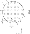
- the conductive layer 4 comprises at least one pattern 26 formed by at least one conductive zone 28 formed by the conductive layer 4 and at least one non-conductive zone 30, each conductive zone 28 of the pattern 26 being a zone full of conductive layer 4 and each non-conductive zone 30 of pattern 26 being formed by a through opening 32 made through conductive layer 4.
- Each pattern 26 has shapes adapted to define a functional electrical circuit performed a particular function when each conductive zone 28 of pattern 26 is supplied with electricity via an electrical component 6 soldered to conductive layer 4.
- the function performed by the functional electrical circuit is a function of interaction with a user on the front face 20A of the laminate 20.
- the functional electrical circuit is configured to produce a man-machine interface, a user being able to interact with the front face 20A of the laminate 20 to activate, control and/or influence a function carried out by a machine connected to the conductive layer 4 via an electrical component 6.
- the functional electrical circuit is for example a resistive circuit or a capacitive circuit suitable for detecting the contact and/or the proximity of a finger of a user with the front face 20A of the laminate 20 in line with the functional electrical circuit formed by the pattern 18.
- each pattern 26 defines for example a touch button, a touch cursor or a touch surface, in particular a multi-point touch surface defining several points of interaction.
- the functional electrical circuit is for example a resistive heating circuit. This makes it possible to produce a heated motor vehicle part 2, i.e. integrating a heating function.
- Each pattern 26 is connected to an electrical source via an electrical component 6 soldered to the conductive layer 4 for its electricity supply.
- a conductive layer 4 is provided with a pattern 26 or several patterns 26.
- An electrical component 6 makes it possible to connect a pattern 26 or several patterns 26 of a conductive layer 4 to an electrical source.
- the laminate 20 comprises one or more conductive layers 4, each conductive layer 4 being associated with at least one electrical component 6 having a connection portion 8 soldered to this conductive layer 4.
- each conductive layer 4 comprises at least one pattern 26 defining a functional electrical circuit.
- the laminate 20 comprises a conductive layer 4 disposed on the front face of the support layer 22, and in particular, where applicable, a conductive layer 4 interposed between the support layer 22 and the decorative layer 24.
- the laminate comprises a conductive layer 4 covering the rear face 22B of the support layer 22.
- the laminate 20 comprises for example a single conductive layer 4 placed on the front face 22A of the support layer 22, a single conductive layer 4 placed on the rear face 22B of the support layer 22, or two conductive layers 4.
- the laminate 20 comprises two conductive layers 4, and preferably these conductive layers 4 are located on either side of the support layer 22, which is sandwiched between the two conductive layers 4. Each conductive layer 4 is preferably in contact with a respective face of the support layer 22.
- An embodiment with two conductive layers 4 is particularly suitable for the production of a capacitive sensor using two functional electrical circuits, each functional electrical circuit being formed in a respective conductive layer 4 among the two conductive layers 4, the two electrical circuits being superimposed.
- a capacitive sensor makes it possible to detect a contact and/or the proximity of a user's finger.
- Each conductive layer 4 is fixed on the support layer 20 for example by applying the conductive layer 4 against the support layer 20 with pressurization and/or heating.
- the support layer 22 is made of a thermoplastic material or comprises a thermoplastic matrix, this makes it possible to obtain adhesion between the thermoplastic matrix of the support layer 22 and the thermoplastic fibers of the conductive layer 4.
- Adhesion is particularly good when the thermoplastic fibers and the thermoplastic material or the thermoplastic matrix are made of the same material, for example polypropylene.
- each conductive layer 4 is fixed to the support layer 22 by bonding, using a layer of glue interposed between the conductive layer 4 and the support layer 22.
- Each conductive layer 4 made of a textile formed from conductive fibers and thermoplastic fibers and applied against the support layer 22 to obtain the laminate 20, reinforces the support layer 22 and thus defines a reinforcement layer.
- a conductive layer 4 made of a textile formed from carbon fibers and thermoplastic fibers, in particular polypropylene fibers.
- a method of making part 2 includes providing a backing layer 22, providing at least one conductive layer 4, and assembling the backing layer 22 with each conductive layer 4 to form a laminate 20 , for example by pressurizing and/or heating.
- the manufacturing method comprises the production of each pattern 26 in each conductive layer 4, and providing one or more through opening(s) 32 through this conductive layer 4.
- Each through opening 32 formed in a conductive layer 4 is hollowed out over the entire thickness of this conductive layer 4, for example by laser machining, by mechanical machining and/or by chemical attachment.
- each pattern 26 in each conductive layer 4 is carried out after application and fixing of the conductive layer 4 on the support layer 22.
- the manufacturing process includes, where appropriate, the assembly of the decorative layer 24, for example on the front face 22A of the support layer 22 or on a conductive layer 4 covering the front face 22A of the support layer 22
- the fixing is carried out for example by gluing.
- the invention is not limited to the exemplary embodiments and to the variants described above.
- the electrical conductor 12 is in contact with the conductive layer 4, the sheath 10 extending from the side of the electrical conductor 12 opposite to the conductive layer 4 and covering the electrical conductor 12.
- the part of the electrical conductor 12 opposite the conductive layer 4 in the electrical contact portions 12A is not covered with sheath 10.
Landscapes
- Engineering & Computer Science (AREA)
- Mechanical Engineering (AREA)
- Textile Engineering (AREA)
- Manufacturing & Machinery (AREA)
- Laminated Bodies (AREA)
Applications Claiming Priority (1)
| Application Number | Priority Date | Filing Date | Title |
|---|---|---|---|
| FR2012684A FR3117072B1 (fr) | 2020-12-04 | 2020-12-04 | Pièce comprenant une couche conductrice et procédé de fabrication d’une telle pièce |
Publications (2)
| Publication Number | Publication Date |
|---|---|
| EP4008591A1 true EP4008591A1 (de) | 2022-06-08 |
| EP4008591B1 EP4008591B1 (de) | 2024-09-04 |
Family
ID=74669026
Family Applications (1)
| Application Number | Title | Priority Date | Filing Date |
|---|---|---|---|
| EP21212171.9A Active EP4008591B1 (de) | 2020-12-04 | 2021-12-03 | Bauteil mit einer leiterschicht und verfahren zur herstellung eines solchen bauteils |
Country Status (3)
| Country | Link |
|---|---|
| EP (1) | EP4008591B1 (de) |
| CN (1) | CN114596979A (de) |
| FR (1) | FR3117072B1 (de) |
Citations (2)
| Publication number | Priority date | Publication date | Assignee | Title |
|---|---|---|---|---|
| US20100276497A1 (en) * | 2007-12-13 | 2010-11-04 | Gemalto Sa | Method of producing a device comprising at least two distinct components that are interconnected by interconnecting wires and a device thereby obtained |
| US20170245326A1 (en) * | 2016-02-19 | 2017-08-24 | Gerflor | Multilayer Structure for the Production of a Heating Floor or Wall Covering |
-
2020
- 2020-12-04 FR FR2012684A patent/FR3117072B1/fr active Active
-
2021
- 2021-12-03 EP EP21212171.9A patent/EP4008591B1/de active Active
- 2021-12-03 CN CN202111467258.9A patent/CN114596979A/zh active Pending
Patent Citations (2)
| Publication number | Priority date | Publication date | Assignee | Title |
|---|---|---|---|---|
| US20100276497A1 (en) * | 2007-12-13 | 2010-11-04 | Gemalto Sa | Method of producing a device comprising at least two distinct components that are interconnected by interconnecting wires and a device thereby obtained |
| US20170245326A1 (en) * | 2016-02-19 | 2017-08-24 | Gerflor | Multilayer Structure for the Production of a Heating Floor or Wall Covering |
Also Published As
| Publication number | Publication date |
|---|---|
| FR3117072A1 (fr) | 2022-06-10 |
| EP4008591B1 (de) | 2024-09-04 |
| FR3117072B1 (fr) | 2024-04-26 |
| CN114596979A (zh) | 2022-06-07 |
Similar Documents
| Publication | Publication Date | Title |
|---|---|---|
| EP3051698B1 (de) | Bedientafel für fahrzeug, und verfahren zur herstellung einer solchen bedientafel | |
| CA2461341C (fr) | Procede pour fabriquer une vitre en matiere plastique avec une structure de conducteurs electriques et vitre en matiere plastique avec fils noyes | |
| FR3116473A1 (fr) | Elément de garnissage comprenant un élément de chauffage et un capteur de proximité | |
| FR3116474A1 (fr) | Elément de garnissage comprenant un élément de chauffage en un matériau carbone | |
| EP0917688B1 (de) | Kombinierte chipkarte | |
| FR2798209A1 (fr) | Procede de fabrication de cartes a puce | |
| WO2004025553A1 (fr) | Procede de fabrication d'une carte a puce sans contact ou hybride contact-sans contact a planete renforcee | |
| EP2674274B1 (de) | Verpackungselement und Verfahren zu seiner Herstellung | |
| FR3121404A1 (fr) | Elément de garnissage rétroéclairé comprenant une couche fonctionnelle en matériau carbone | |
| FR2871119A1 (fr) | Element moule en mousse chauffe electriquement, essentiellement element d'assise equipant un interieur de vehicule ainsi que le procede de realisation correspondant | |
| FR3043952A1 (fr) | Panneau de commande a capteur piezoelectrique souple pour un vehicule | |
| EP3448824B1 (de) | Verbundglas mit einem satz von dioden | |
| FR3017598A1 (fr) | Panneau d'aeronef pour un espace interieur d'un aeronef ou avion et son procede de fabrication | |
| EP0902927B1 (de) | Speicherkarte und verfahren zu ihrer herstellung | |
| EP4008591B1 (de) | Bauteil mit einer leiterschicht und verfahren zur herstellung eines solchen bauteils | |
| FR3116489A1 (fr) | Elément de garnissage comprenant une couche fonctionnelle en matériau carbone | |
| FR3116488A1 (fr) | Elément de garnissage comprenant une couche de décor en matériau carbone | |
| FR2923177A1 (fr) | Procede d'assemblage d'une piece composite | |
| FR3117073A1 (fr) | Elément de garnissage comprenant un élément fonctionnel en matériau composite pyrolysé | |
| EP2511809A1 (de) | Verfahren zur Herstellung eines berührungsempfindlichen kapazitiven Sensors | |
| FR3134070A1 (fr) | Elément de garnissage comprenant un élément de chauffage discret en matériau carbone | |
| FR3121640A1 (fr) | Panneau de commande pour véhicule et procédé de réalisation | |
| WO2023237655A1 (fr) | Préforme pour fabriquer une pièce en matériau composite comprenant un capteur capacitif, procédé de fabrication d'une telle préforme, pièce en matériau composite et procédé de fabrication associés | |
| EP3521001A1 (de) | Vorimprägniertes teil, das eine hautpschicht und eine verstärkungsschicht umfasst | |
| FR3133568A1 (fr) | Elément de garnissage comprenant une couche fonctionnelle en peinture conductrice |
Legal Events
| Date | Code | Title | Description |
|---|---|---|---|
| PUAI | Public reference made under article 153(3) epc to a published international application that has entered the european phase |
Free format text: ORIGINAL CODE: 0009012 |
|
| STAA | Information on the status of an ep patent application or granted ep patent |
Free format text: STATUS: THE APPLICATION HAS BEEN PUBLISHED |
|
| AK | Designated contracting states |
Kind code of ref document: A1 Designated state(s): AL AT BE BG CH CY CZ DE DK EE ES FI FR GB GR HR HU IE IS IT LI LT LU LV MC MK MT NL NO PL PT RO RS SE SI SK SM TR |
|
| STAA | Information on the status of an ep patent application or granted ep patent |
Free format text: STATUS: REQUEST FOR EXAMINATION WAS MADE |
|
| 17P | Request for examination filed |
Effective date: 20221115 |
|
| RBV | Designated contracting states (corrected) |
Designated state(s): AL AT BE BG CH CY CZ DE DK EE ES FI FR GB GR HR HU IE IS IT LI LT LU LV MC MK MT NL NO PL PT RO RS SE SI SK SM TR |
|
| GRAP | Despatch of communication of intention to grant a patent |
Free format text: ORIGINAL CODE: EPIDOSNIGR1 |
|
| STAA | Information on the status of an ep patent application or granted ep patent |
Free format text: STATUS: GRANT OF PATENT IS INTENDED |
|
| INTG | Intention to grant announced |
Effective date: 20240423 |
|
| GRAS | Grant fee paid |
Free format text: ORIGINAL CODE: EPIDOSNIGR3 |
|
| GRAA | (expected) grant |
Free format text: ORIGINAL CODE: 0009210 |
|
| STAA | Information on the status of an ep patent application or granted ep patent |
Free format text: STATUS: THE PATENT HAS BEEN GRANTED |
|
| AK | Designated contracting states |
Kind code of ref document: B1 Designated state(s): AL AT BE BG CH CY CZ DE DK EE ES FI FR GB GR HR HU IE IS IT LI LT LU LV MC MK MT NL NO PL PT RO RS SE SI SK SM TR |
|
| REG | Reference to a national code |
Ref country code: GB Ref legal event code: FG4D Free format text: NOT ENGLISH |
|
| REG | Reference to a national code |
Ref country code: CH Ref legal event code: EP |