EP4008575B1 - Procédé et appareil pour déterminer un impact sur une unité à température contrôlée - Google Patents
Procédé et appareil pour déterminer un impact sur une unité à température contrôlée Download PDFInfo
- Publication number
- EP4008575B1 EP4008575B1 EP21210195.0A EP21210195A EP4008575B1 EP 4008575 B1 EP4008575 B1 EP 4008575B1 EP 21210195 A EP21210195 A EP 21210195A EP 4008575 B1 EP4008575 B1 EP 4008575B1
- Authority
- EP
- European Patent Office
- Prior art keywords
- temperature
- controlled unit
- components
- acceleration
- change
- Prior art date
- Legal status (The legal status is an assumption and is not a legal conclusion. Google has not performed a legal analysis and makes no representation as to the accuracy of the status listed.)
- Active
Links
- 238000000034 method Methods 0.000 title claims description 25
- 230000008859 change Effects 0.000 claims description 53
- 230000001133 acceleration Effects 0.000 claims description 52
- 238000001514 detection method Methods 0.000 claims description 15
- 238000001816 cooling Methods 0.000 claims description 8
- 238000012544 monitoring process Methods 0.000 claims description 8
- 238000011084 recovery Methods 0.000 claims description 6
- 230000004044 response Effects 0.000 claims description 6
- 230000000977 initiatory effect Effects 0.000 claims description 3
- 238000003860 storage Methods 0.000 description 8
- 238000005057 refrigeration Methods 0.000 description 7
- 238000004891 communication Methods 0.000 description 5
- 238000010586 diagram Methods 0.000 description 4
- 238000005516 engineering process Methods 0.000 description 3
- 230000003247 decreasing effect Effects 0.000 description 2
- 230000002349 favourable effect Effects 0.000 description 2
- 230000006870 function Effects 0.000 description 2
- 230000004048 modification Effects 0.000 description 2
- 238000012986 modification Methods 0.000 description 2
- 238000012545 processing Methods 0.000 description 2
- 230000005856 abnormality Effects 0.000 description 1
- 230000004075 alteration Effects 0.000 description 1
- 230000001413 cellular effect Effects 0.000 description 1
- 238000010276 construction Methods 0.000 description 1
- 230000002542 deteriorative effect Effects 0.000 description 1
- 238000009826 distribution Methods 0.000 description 1
- 239000000446 fuel Substances 0.000 description 1
- 230000007774 longterm Effects 0.000 description 1
- 238000007726 management method Methods 0.000 description 1
- 238000004519 manufacturing process Methods 0.000 description 1
- 230000000116 mitigating effect Effects 0.000 description 1
- 238000010295 mobile communication Methods 0.000 description 1
- 238000012806 monitoring device Methods 0.000 description 1
- 230000008520 organization Effects 0.000 description 1
- 238000004806 packaging method and process Methods 0.000 description 1
- 239000000825 pharmaceutical preparation Substances 0.000 description 1
- 229940127557 pharmaceutical product Drugs 0.000 description 1
- 230000000644 propagated effect Effects 0.000 description 1
- 239000002096 quantum dot Substances 0.000 description 1
- 230000007723 transport mechanism Effects 0.000 description 1
Images


Classifications
-
- B—PERFORMING OPERATIONS; TRANSPORTING
- B60—VEHICLES IN GENERAL
- B60H—ARRANGEMENTS OF HEATING, COOLING, VENTILATING OR OTHER AIR-TREATING DEVICES SPECIALLY ADAPTED FOR PASSENGER OR GOODS SPACES OF VEHICLES
- B60H1/00—Heating, cooling or ventilating [HVAC] devices
- B60H1/00642—Control systems or circuits; Control members or indication devices for heating, cooling or ventilating devices
- B60H1/00735—Control systems or circuits characterised by their input, i.e. by the detection, measurement or calculation of particular conditions, e.g. signal treatment, dynamic models
- B60H1/00764—Control systems or circuits characterised by their input, i.e. by the detection, measurement or calculation of particular conditions, e.g. signal treatment, dynamic models the input being a vehicle driving condition, e.g. speed
-
- B—PERFORMING OPERATIONS; TRANSPORTING
- B60—VEHICLES IN GENERAL
- B60H—ARRANGEMENTS OF HEATING, COOLING, VENTILATING OR OTHER AIR-TREATING DEVICES SPECIALLY ADAPTED FOR PASSENGER OR GOODS SPACES OF VEHICLES
- B60H1/00—Heating, cooling or ventilating [HVAC] devices
- B60H1/00507—Details, e.g. mounting arrangements, desaeration devices
- B60H1/00585—Means for monitoring, testing or servicing the air-conditioning
-
- B—PERFORMING OPERATIONS; TRANSPORTING
- B60—VEHICLES IN GENERAL
- B60H—ARRANGEMENTS OF HEATING, COOLING, VENTILATING OR OTHER AIR-TREATING DEVICES SPECIALLY ADAPTED FOR PASSENGER OR GOODS SPACES OF VEHICLES
- B60H1/00—Heating, cooling or ventilating [HVAC] devices
- B60H1/00007—Combined heating, ventilating, or cooling devices
- B60H1/00014—Combined heating, ventilating, or cooling devices for load cargos on load transporting vehicles
-
- B—PERFORMING OPERATIONS; TRANSPORTING
- B60—VEHICLES IN GENERAL
- B60H—ARRANGEMENTS OF HEATING, COOLING, VENTILATING OR OTHER AIR-TREATING DEVICES SPECIALLY ADAPTED FOR PASSENGER OR GOODS SPACES OF VEHICLES
- B60H1/00—Heating, cooling or ventilating [HVAC] devices
- B60H1/00642—Control systems or circuits; Control members or indication devices for heating, cooling or ventilating devices
- B60H1/00978—Control systems or circuits characterised by failure of detection or safety means; Diagnostic methods
-
- B—PERFORMING OPERATIONS; TRANSPORTING
- B60—VEHICLES IN GENERAL
- B60H—ARRANGEMENTS OF HEATING, COOLING, VENTILATING OR OTHER AIR-TREATING DEVICES SPECIALLY ADAPTED FOR PASSENGER OR GOODS SPACES OF VEHICLES
- B60H1/00—Heating, cooling or ventilating [HVAC] devices
- B60H1/00642—Control systems or circuits; Control members or indication devices for heating, cooling or ventilating devices
- B60H1/00985—Control systems or circuits characterised by display or indicating devices, e.g. voice simulators
-
- B—PERFORMING OPERATIONS; TRANSPORTING
- B60—VEHICLES IN GENERAL
- B60H—ARRANGEMENTS OF HEATING, COOLING, VENTILATING OR OTHER AIR-TREATING DEVICES SPECIALLY ADAPTED FOR PASSENGER OR GOODS SPACES OF VEHICLES
- B60H1/00—Heating, cooling or ventilating [HVAC] devices
- B60H1/32—Cooling devices
- B60H1/3204—Cooling devices using compression
- B60H1/3205—Control means therefor
- B60H1/3208—Vehicle drive related control of the compressor drive means, e.g. for fuel saving purposes
-
- F—MECHANICAL ENGINEERING; LIGHTING; HEATING; WEAPONS; BLASTING
- F25—REFRIGERATION OR COOLING; COMBINED HEATING AND REFRIGERATION SYSTEMS; HEAT PUMP SYSTEMS; MANUFACTURE OR STORAGE OF ICE; LIQUEFACTION SOLIDIFICATION OF GASES
- F25D—REFRIGERATORS; COLD ROOMS; ICE-BOXES; COOLING OR FREEZING APPARATUS NOT OTHERWISE PROVIDED FOR
- F25D29/00—Arrangement or mounting of control or safety devices
- F25D29/003—Arrangement or mounting of control or safety devices for movable devices
-
- G—PHYSICS
- G08—SIGNALLING
- G08C—TRANSMISSION SYSTEMS FOR MEASURED VALUES, CONTROL OR SIMILAR SIGNALS
- G08C17/00—Arrangements for transmitting signals characterised by the use of a wireless electrical link
- G08C17/02—Arrangements for transmitting signals characterised by the use of a wireless electrical link using a radio link
-
- B—PERFORMING OPERATIONS; TRANSPORTING
- B60—VEHICLES IN GENERAL
- B60H—ARRANGEMENTS OF HEATING, COOLING, VENTILATING OR OTHER AIR-TREATING DEVICES SPECIALLY ADAPTED FOR PASSENGER OR GOODS SPACES OF VEHICLES
- B60H1/00—Heating, cooling or ventilating [HVAC] devices
- B60H1/32—Cooling devices
- B60H1/3204—Cooling devices using compression
- B60H1/3232—Cooling devices using compression particularly adapted for load transporting vehicles
Definitions
- the present invention generally relates to temperature-controlled units used in transportation systems. More particularly, the invention relates to a server, an apparatus and a method for determining an impact on components of a temperature-controlled unit in a vehicle.
- Perishable items or goods are usually kept inside a temperature-controlled unit of a vehicle to provide a favorable environment to prevent them from deteriorating during transportation.
- roads may be damaged or may have slippery surface resulting in an accident or a collision of the vehicle with another object, like a vehicle.
- hard brakes need to be applied by the driver that would result in sudden deceleration of the vehicle.
- sudden deceleration can cause damage to the temperature-controlled unit of the vehicle and eventually its operations can be hindered.
- WO 2020/129380 A1 discloses a shipping container having a container refrigeration apparatus.
- the apparatus comprises a controller configured to determine whether or not a strong impact (experienced e.g. during relocation via a crane) acted on the container and to diagnose whether or not the container the refrigeration apparatus itself has an abnormality when a strong impact is determined to have acted on the container.
- EP 3543817 A1 discloses a system for dynamically mitigating resonance in a transport refrigeration unit.
- US 2020/074395 A1 discloses a freight car including an internet-of-things controller for controlling transport refrigeration-related aspects of the freight car.
- a method for determining an impact on components of a temperature-controlled unit of a road vehicle as claimed in claim 1.
- the method may comprise the step of determining one or more faults in the temperature-controlled unit based on the impact on the one or more components of the temperature-controlled unit.
- the one or more faults may be determined by comparing information of each parameter of the temperature-controlled unit with predetermined values of the parameters.
- the method may comprise the step of automatically initiating a recovery process for the one or more components based on the one or more faults determined in the temperature-controlled unit.
- the method may comprise the step of storing information related to the detection of the change in acceleration and/or the one or more parameters associated with the one or more components in a memory.
- the information may be erased from the memory in an event no impact is determined on the one or more components of the temperature-controlled unit due to the change in the acceleration.
- the one or more parameters associated with the one or more components may be monitored by the temperature-controlled unit of the road vehicle.
- the change in acceleration of the road vehicle may be detected using one or more sensors associated with the temperature-controlled unit.
- the one or more sensors may correspond to a tri-axis accelerometer sensor and a gyroscope.
- the one or more components of the temperature-controlled unit may comprise a compressor, an evaporator, a fan of the evaporator, heater coils, cooling coils, a condenser, fans of the condenser, a dry filter, a heat exchanger, a defrost magnetic valve, and/or stepper valves.
- a server for determining an impact on components of a temperature-controlled unit of a road vehicle as claimed in claim 10.
- the determination unit may be configured to determine one or more faults in the temperature-controlled unit based on the impact on the one or more components of the temperature-controlled unit.
- the one or more faults may be determined by comparing information of each parameter of the temperature-controlled unit with predetermined values of the parameters.
- the change in acceleration of the road vehicle may be detected using one or more sensors associated with the temperature-controlled unit.
- the one or more sensors may correspond to a tri-axis accelerometer sensor and a gyroscope.
- the one or more components of the temperature-controlled unit may comprise a compressor, an evaporator, a fan of the evaporator, heater coils, cooling coils, a condenser, fans of the condenser, a dry filter, a heat exchanger, a defrost magnetic valve, and/or stepper valves.
- the one or more sensors associated with the temperature-controlled unit may correspond to a tri-axis accelerometer sensor and a gyroscope.
- the one or more components of the temperature-controlled unit may comprise a compressor, an evaporator, a fan of the evaporator, heater coils, cooling coils, a condenser, fans of the condenser, a dry filter, a heat exchanger, a defrost magnetic valve, and/or stepper valves.
- the temperature-controlled unit of the vehicle may contain goods (such as pharmaceutical products, food items or other sensitive good).
- the apparatus may be integrated, embedded or plugged-in in the temperature-controlled unit.
- the apparatus may detect a change in acceleration of the vehicle using one or more sensors. Such a change in the apparatus can be due to application of hard brakes by a driver to avoid an accident or a collision.
- the apparatus may monitor one or more parameters associated with one or more components of the temperature-controlled unit. Accordingly, the apparatus may transmit information of the one or more monitored parameters to a server through a network.
- the server may then determine an impact on the one or more components of the temperature-controlled unit due to the change in the acceleration based on the information of the one or more monitored parameters.
- the vehicle is a road vehicle (such as a two-wheeler, a three-wheeler, a four-wheeler).
- the apparatus may be a device or an electronic circuitry capable of monitoring the one or more parameters inside the temperature-controlled unit.
- the monitoring device may comprise, but is not limited to, sensors such as accelerometer, gyroscope, temperature sensor, pressure sensor, a transmitting unit, a receiving unit, a monitoring unit, a processor, and a memory. Functions and operations performed by the apparatus are described in details below.
- the one or more components of the temperature-controlled unit comprise a compressor, an evaporator, a fan of the evaporator, heater coils, cooling coils, a condenser, fans of the condenser, a dry filter, a heat exchanger, a defrost magnetic valve, and/or stepper valves and/or any such component that is well known in the art.
- the temperature-controlled unit may be a refrigerated container or reefer placed inside the vehicle.
- the temperature-controlled unit may contain goods.
- the server may be a remote storage, a database, a cloud or any such remote memory that is well known in the art.
- the network may be any cellular network (such as Global System for Mobile communication (GSM) network, Code-Division Multiple Access (CDMA) network, Long-Term Evolution (LTE) network), a WiFi network, a bluetooth network, a ZigBee network, a near-field communication network, or any such network that is obvious to a person skilled in the art.
- GSM Global System for Mobile communication
- CDMA Code-Division Multiple Access
- LTE Long-Term Evolution
- WiFi Wireless Fidelity
- WiFi Wireless Fidelity
- FIG 1A depicts an exemplary system architecture 100A according to an embodiment of the invention.
- a vehicle 102 may have a temperature-controlled unit 104 and an apparatus 106.
- the apparatus 106 is integrated or embedded with the temperature-controlled unit 104.
- the apparatus 106 is plugged-in to the temperature-controlled unit 104.
- the temperature-controlled unit 104 may also contain goods (not shown).
- the vehicle 102 carrying the goods inside the temperature-controlled unit 104 may be moved from one place to another place for transporting these goods.
- the vehicle 102 may be accelerating or moving at a particular speed (say 40 miles per hour (65 kmph)). Further, hard-brakes may be applied by a driver (not shown) of the vehicle 102 to avoid some collision or an accident. The application of the hard brakes results in sudden change or decrease in acceleration of the vehicle 102. For instance, the speed of the vehicle 102 after the application of the hard-brakes may become 0.1 or 0 miles per hour (0.2 or 0 kmph).
- the apparatus 106 may detect such sudden change or decrease in acceleration of the vehicle 102 using one or more sensors.
- the one or more sensors correspond to a tri-axis accelerometer sensor and/or a gyroscope. Using the tri-axis accelerometer sensor together with the gyroscope may increase the accuracy for detecting the change in the acceleration.
- the sudden change or decrease in acceleration of the vehicle 102 may be detected when the speed of the vehicle 102 is suddenly decreased within fractions of seconds.
- Figure 1B depicts an exemplary graph 100B showing a sudden decrease in the acceleration/speed of the vehicle 102 at 5 th second where the speed is almost 0 miles per hour whereas the speed is almost 40 miles per hour (65 kmph) at 4 th second.
- the apparatus 106 may monitor one or more parameters associated with one or more components of the temperature-controlled unit 104.
- various kinds of different sensors like pressure sensors, temperature sensors, voltage sensors, current sensors, air sensors, humidity sensors may be used for each components in the temperature-controlled unit 104 to monitor the one or more parameters associated with one or more components.
- a humidity level inside the temperature-controlled unit 104 may be monitored using a humidity sensor of the temperature-controlled unit 104.
- pressure of a condenser of the temperature-controlled unit 104 may be monitored using a pressure sensor of the temperature-controlled unit 104.
- a speed of a fan of the condenser, a compressor, an evaporator of the temperature-controlled unit 104 may be monitored using a speed sensor of the temperature-controlled unit 104.
- current and voltage supplied to the temperature-controlled unit 104 may be monitored using a current sensor and a voltage sensor of the temperature-controlled unit 104.
- the one or more components of the temperature-controlled unit 104 comprise a compressor, an evaporator, a fan of the evaporator, heater coils, cooling coils, a condenser, fans of the condenser, a dry filter, a heat exchanger, a defrost magnetic valve, an engine, and/or stepper valves.
- the one or more parameters comprises a temperature in the temperature-controlled unit, current supplied to the temperature-controlled unit, voltage at which the temperature-controlled unit is operated, current of a compressor of the temperature-controlled unit, a discharge pressure of the compressor, a suction pressure of the compressor, a discharge temperature of the compressor, a suction temperature of the compressor, an economizer pressure of an economizer valve, an economizer temperature of the of economizer valve, an outlet temperature of an evaporator of the temperature-controlled unit, an outlet pressure of the evaporator, a supply air temperature of the temperature-controlled unit, a return air temperature of the refrigeration unit, a humidity level inside the temperature-controlled unit, a position of a compressor suction modulation valve, a position of a evaporator expansion valve, a position of a clutch, a pressure of a condenser, a speed of a fan of the condenser, a speed of a fan of the evaporator, a display board temperature an input board
- the apparatus 106 may transmit information of the one or more monitored parameters to a server 110 through a network 108 after detecting change in acceleration.
- the server 110 determines an impact on the one or more components of the temperature-controlled unit 104 due to the change in the acceleration of the vehicle 102.
- the server 110 may use the information of the one or more monitored parameters by comparing the information of each parameter of the temperature-controlled unit 104 with predetermined values of the parameters.
- predetermined values of the parameters may be set or defined by a manufacturer of the temperature-controlled unit 104 and can be updated at the server 110 by any staff member of the manufacturer.
- the predetermined values of the parameters may be obtained from data lake collection of the refrigeration parameters.
- the server 110 may determine that the current supplied to the temperature-controlled unit 104 has been stopped after the detection of the change in acceleration based on the comparison of the current supplied to the temperature-controlled unit 104 before and after the detection.
- speed of a fan of an evaporator before detection of the change in acceleration was 50 rotation per minute (rpm) and was 10 rpm after such detection.
- the server 110 may determine that the speed of the evaporator's fan of the temperature-controlled unit 104 has been decreased after the detection of the change in acceleration based on the comparison.
- the server 110 may determine that current supply and the evaporator's fan has been impacted after the detection of the change in acceleration of the vehicle.
- the deviation of the parameters from their customary values may represent the impact to the change in acceleration.
- the server may receive a set of values or in the form of a graphical representation.
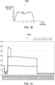
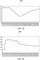
- Figure 1C depicts an exemplary graph 100C showing an impact on current at and after 03:21 PM. It can be seen in the graph 100C that AC Currents 1, 2, 3 before 3:21 PM is 18A, 37A, 37A respectively and after 3:21 PM, the AC Currents 1, 2, 3 is 1A, 2A, 3A.
- Figure 1D depicts an exemplary graph 100D showing an impact on humidity level at 03:21 PM. It can be seen in the graph 100D that the relative humidity before 3:21 PM is 97% respectively and after 3:21 PM, the relative humidity is 88%.
- Figure 1E depicts an exemplary graph 100E showing an impact on a condenser pressure at 03:21 PM. It can be seen in the graph 100E that the condenser pressure at 03:21 PM is 230 psi (pound per square inch) (1.6 MPa) and after 03:21 PM, the condenser pressure is 170 psi (1.2 MPa).
- Figure 1F depicts an exemplary graph 100F showing an impact on a suction modulation valve at 03:21 PM. It can be seen in the graph 100F that the suction modulation valve at 03:21 PM is 27% open and after 03:21 PM, the suction modulation valve is closed to 0% and then opens at 15%.
- Figure 1G depicts an exemplary graph 100G showing an impact on a condenser fan and compressor at 03:21 PM. It can be seen in the graph 100G that the compressor and condenser fan goes off at 3:21 PM.
- Figure 1H depicts an exemplary graph 100H showing no impact on an a low evaporator fan and a high evaporator fan at 03:21 PM.
- Figure 11 depicts an exemplary graph 100I showing an impact on a supply air temperature at 03:21 PM.
- Figure 1J depicts an exemplary graph 100J showing an impact on a return air temperature at 03:21 PM.
- FIG. 100K depicts an exemplary graph 100K showing an impact on a secondary return temperature at 03:21 PM.
- Figure 1L depicts an exemplary graph 100L showing an impact on a defrost termination sensor reading at 03:21 PM.
- the server 110 may transmit a notification to a device 112 through the network 108.
- the device 112 may be associated with a person 114 who can be a driver of the vehicle, an owner of the manufacturer of the goods, an owner of the vehicle 102, an insurance provider, a hospital for emergency, a technician for repairing the vehicle 102, or any other service.
- a timely and an informed decision can be taken by the person 114.
- the server 110 may determine one or more faults in the temperature-controlled unit 104 based on the impact on the one or more components of the temperature-controlled unit 104. Taking the above example, the server 110 determines that the current supply and the evaporator's fan has become faulty as the current is not supplied to the temperature-controlled unit 104 and the evaporator's fan is not rotating and thus, has stopped providing air. Based on one or more determined faults in the temperature-controlled unit 104, the server 110 may automatically initiate a recovery process for the one or more components based on the one or more faults determined in the temperature-controlled unit 104. For an example, an automatic restart of the evaporator or the current source may be initiated by the server at the temperature-controlled unit 104. Such automated recovery process may help in early recovery from the damage or the impact of the change in acceleration.
- the server 110 stores the information related to the detection of the change in acceleration and/or the information of one or more parameters associated with the one or more components in a memory for future.
- the information is saved in the memory with date, time, year of the detection of the change in acceleration and can be helpful in legal case scenario.
- the server 110 may erase such information.
- FIG. 2 depicts block diagram of different components of an exemplary apparatus 106 according to an exemplary embodiment of the invention.
- the apparatus 106 may comprise, but is not limited to, a transmitting unit 202, a receiving unit 204, a monitoring unit 206, one or more sensors 208, a memory 210, and/or a processor 212.
- the one or more sensors 208 may include, but is not limited to, pressure sensors, temperature sensors, voltage sensors, current sensors, air sensors, humidity sensors, a tri-axis accelerometer, and a gyroscope.
- the tri-axis accelerometer and/or the gyroscope sensors may be configured to detect a change in acceleration of a vehicle 102.
- the monitoring unit 206 may be configured to monitor one or more parameters associated with one or more components of the temperature-controlled unit 104 using the rest of the sensors as explained above. Further, the transmitting unit 202 may be configured to transmit information of the one or more monitored parameters to a server 110 to determine an impact on the one or more components of the temperature-controlled unit 104 due to the change in the acceleration.
- the receiving unit 204 may be configured to receive any communication from the server 110.
- the memory 210 may be configured to store information of the one or more monitored parameters as monitored by the sensors.
- the processor 212 may be configured to read values from the sensors 208, read information from the monitoring unit 206 and read information from the memory 210.
- the transmitting unit 202, the receiving unit 204, the monitoring unit 206, the one or more sensors 208, and/or the memory 210 may be communicably coupled with the processor 212.
- the different units described herein are exemplary. The invention may be performed using one or more units. For example, the tasks executed by the transmitting unit 202, the receiving unit 204, the monitoring unit 206, the one or more sensors 208, and/or the memory 210 and/or the processor 212 may be performed by a single unit. Alternatively, more number of units than described herein may be used to perform the present invention.
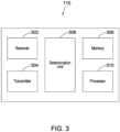
- FIG. 3 depicts block diagram of different components of an exemplary server 110 according to an exemplary embodiment of the invention.
- the server 110 may comprise, but is not limited to, a receiver 302, a transmitter 304, a determination unit 306, a memory 308, and/or a processor 310.
- the receiver 302 may be configured to receive information of one or more parameters associated with one or more components of a temperature-controlled unit 104 of a vehicle 102. Also, the information of the one or more parameters are received in response to a change in acceleration of the vehicle 102.
- the determination unit 306 may be configured to determine an impact on the one or more components of the temperature-controlled unit 104 due to the change in the acceleration. For this, the determination unit 306 may communicate with the processor 310 to perform comparison as explained above.
- the transmitter 304 may be configured to transmit a notification to a device 112 based on the impact on the one or more components of the temperature-controlled unit 104.
- the memory 308 may be configured to store information related to the detection of the change in acceleration and/or the one or more parameters associated with the one or more components.
- the memory 308 and the processor 310 may be configured to erase the information from the memory in an event no impact is determined on the one or more components of the temperature-controlled unit 104 due to the change in the acceleration.
- the receiver 302, the transmitter 304, the determination unit 306, the memory 308 may be communicably coupled with the processor 310.
- the different units described herein are exemplary. The invention may be performed using one or more units. For example, the tasks executed by the receiver 302, the transmitter 304, the determination unit 306, the memory 308 and/or the processor 310 may be performed by a single unit. Alternatively, more number of units than described herein may be used to perform the present invention.
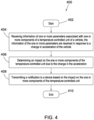
- FIG. 4 depicts a flowchart outlining the features of the invention in an embodiment of the invention.
- the method flowchart 400 describes a method for determining an impact on components of a temperature-controlled unit of a vehicle 102.
- the method flowchart 400 starts at step 402.
- a server 110 may receive information of one or more parameters associated with one or more components of a temperature-controlled unit 104 of a vehicle 102. Further, the information of the one or more parameters are received in response to a change in acceleration of the vehicle 102. This has been discussed in greater details in Figure 1A above.
- the server 110 may determine an impact on the one or more components of the temperature-controlled unit 104 due to the change in the acceleration. This has been discussed in greater details in Figure 1A above.
- the server 110 may transmit a notification to a device 112 based on the impact on the one or more components of the temperature-controlled unit 104. This has been discussed in greater details in Figure 1A above. Then, the method 400 may end at step 410.
- the invention can be operated using the one or more computer readable devices.
- the one or more computer readable devices can be associated with an apparatus 106.
- a computer readable medium comprises one or more processors and a memory coupled to the one or more processors, the memory stores instructions executed by the one or more processors.
- the one or more processors is configured to detect a change in acceleration of a vehicle 102. Also, the one or more sensors associated with a temperature-controlled unit 104 of the vehicle 102.
- the one or more processors is also configured to monitor one or more parameters associated with one or more components of the temperature-controlled unit 104 in response to detection of the change in the acceleration.
- the one or more processors is also configured to transmit information of the one or more monitored parameters to a server 110 to determine an impact on the one or more components of the temperature-controlled unit 104 due to the change in the acceleration.
- the present invention is applicable in various industries/fields such as pharmaceutical industry, transportation industry, delivery management industry, manufacturing, distribution and packaging industry and any such industry/field that is well known in the art and where the apparatus 106 is used.
- Exemplary computer readable media includes flash memory drives, digital versatile discs (DVDs), compact discs (CDs), floppy disks, and tape cassettes.
- Computer readable media comprise computer storage media and communication media.
- Computer storage media include volatile and nonvolatile, removable and non-removable media implemented in any method or technology for storage of information such as computer readable instructions, data structures, program modules or other data.
- Computer storage media are tangible and mutually exclusive to communication media.
- Computer storage media are implemented in hardware and exclude carrier waves and propagated signals.
- Computer storage media for purposes of this invention are not signals per se.
- Exemplary computer storage media include hard disks, flash drives, and other solid-state memory.
- communication media typically embody computer readable instructions, data structures, program modules, or other data in a modulated data signal such as a carrier wave or other transport mechanism and include any information delivery media.
- Examples of the invention may be described in the general context of computer-executable instructions, such as program modules, executed by one or more computers or other devices in software, firmware, hardware, or a combination thereof.
- the computer-executable instructions may be organized into one or more computer-executable components or modules.
- program modules include, but are not limited to, routines, programs, objects, components, and data structures that perform particular tasks or implement particular abstract data types.
- aspects of the invention may be implemented with any number and organization of such components or modules. For example, aspects of the invention are not limited to the specific computer-executable instructions or the specific components or modules illustrated in the Figures and described herein. Other examples of the invention may include different computer-executable instructions or components having more or less functionality than illustrated and described herein. Aspects of the invention transform a general-purpose computer into a special-purpose computing device when configured to execute the instructions described herein.
- controller can refer to substantially any processor or computing processing unit or device comprising, but not limited to comprising, a direct digital control of a HVAC system, single-core processors; single-processors with software multithread execution capability; multi-core processors; multi-core processors with software multithread execution capability; multi-core processors with hardware multithread technology; parallel platforms; and parallel platforms with distributed shared memory.
- a processor can refer to an integrated circuit, an application specific integrated circuit (ASIC), a digital signal processor (DSP), a field programmable gate array (FPGA), a programmable logic controller (PLC), a complex programmable logic device (CPLD), a discrete gate or transistor logic, discrete hardware components, or any combination thereof designed to perform the functions described herein.
- ASIC application specific integrated circuit
- DSP digital signal processor
- FPGA field programmable gate array
- PLC programmable logic controller
- CPLD complex programmable logic device
- a processor may also be implemented as a combination of computing processing units.
Claims (15)
- Procédé comprenant :la réception d'informations d'un ou de plusieurs paramètres associés à un ou à plusieurs composants d'une unité régulée en température (104) d'un véhicule routier (102), les informations des un ou plusieurs paramètres étant reçues en réponse à un changement dans l'accélération du véhicule routier (102), dans lequel le changement dans l'accélération du véhicule routier (102) est détecté dans le cas où des freins durs du véhicule routier (102) sont appliqués ;la détermination d'un impact sur les un ou plusieurs composants de l'unité régulée en température (104) dû au changement dans l'accélération ; etla transmission d'une notification à un dispositif (112) sur la base de l'impact sur les un ou plusieurs composants de l'unité régulée en température (104).
- Procédé selon la revendication 1, comprenant en outre la détermination d'un ou de plusieurs défauts dans l'unité régulée en température (104) sur la base de l'impact sur les un ou plusieurs composants de l'unité régulée en température (104).
- Procédé selon la revendication 2, dans lequel les un ou plusieurs défauts sont déterminés par la comparaison d'informations de chaque paramètre de l'unité régulée en température (104) à des valeurs prédéterminées des paramètres.
- Procédé selon la revendication 2 ou 3, comprenant le lancement automatique d'un processus de récupération pour les un ou plusieurs composants sur la base des un ou plusieurs défauts déterminés dans l'unité régulée en température (104).
- Procédé selon une quelconque revendication précédente, comprenant le stockage d'informations liées à la détection du changement dans l'accélération et/ou des un ou plusieurs paramètres associés aux un ou plusieurs composants dans une mémoire ; et
l'effacement des informations de la mémoire dans un cas où aucun impact n'est déterminé sur les un ou plusieurs composants de l'unité régulée en température (104) en raison du changement dans l'accélération. - Procédé selon une quelconque revendication précédente, dans lequel les un ou plusieurs paramètres associés aux un ou plusieurs composants sont surveillés par l'unité régulée en température (104) du véhicule routier (102).
- Procédé selon une quelconque revendication précédente, dans lequel le changement dans l'accélération du véhicule routier (102) est détecté à l'aide d'un ou de plusieurs capteurs associés à l'unité régulée en température (104).
- Procédé selon une quelconque revendication précédente, dans lequel les un ou plusieurs capteurs correspondent à un capteur accélérométrique tri-axe et à un gyroscope.
- Procédé selon une quelconque revendication précédente, dans lequel les un ou plusieurs composants de l'unité régulée en température (104) comprennent un compresseur, un évaporateur, un ventilateur de l'évaporateur, des serpentins chauffants, des serpentins de refroidissement, un condenseur, des ventilateurs du condenseur, un filtre sec, un échangeur de chaleur, une vanne magnétique de dégivrage et/ou des vannes pas à pas.
- Serveur (110) comprenant :un récepteur (302) configuré pour recevoir des informations d'un ou plusieurs paramètres associés à un ou plusieurs composants d'une unité régulée en température (104) d'un véhicule routier (102), les informations des un ou plusieurs paramètres étant reçues en réponse à un changement dans l'accélération du véhicule routier (102), dans lequel le changement dans l'accélération du véhicule routier est détecté dans le cas où des freins durs du véhicule routier (102) sont appliqués ;une unité de détermination (306) configurée pour déterminer un impact sur les un ou plusieurs composants de l'unité régulée en température (104) en raison du changement dans l'accélération ; etun émetteur (304) configuré pour émettre une notification à un dispositif (112) sur la base de l'impact sur les un ou plusieurs composants de l'unité régulée en température (104).
- Serveur (110) selon la revendication 10, dans lequel l'unité de détermination (306) est en outre configurée pour déterminer un ou plusieurs défauts dans l'unité régulée en température (104) sur la base de l'impact sur les un ou plusieurs composants de l'unité régulée en température (104).
- Serveur (110) selon la revendication 11, dans lequel les un ou plusieurs défauts sont déterminés par la comparaison d'informations de chaque paramètre de l'unité régulée en température (104) à des valeurs prédéterminées des paramètres.
- Serveur (110) selon la revendication 10, 11 ou 12, dans lequel :
les un ou plusieurs composants de l'unité régulée en température (104) comprennent un compresseur, un évaporateur, un ventilateur de l'évaporateur, des serpentins chauffants, des serpentins de refroidissement, un condenseur, des ventilateurs du condenseur, un filtre sec, un échangeur de chaleur, une vanne magnétique de dégivrage et/ou des vannes pas à pas. - Appareil (106) comprenant :un ou plusieurs capteurs configurés pour détecter un changement dans l'accélération d'un véhicule routier (102), les un ou plusieurs capteurs (108) étant associés à une unité régulée en température (104) du véhicule routier (102), dans lequel le changement dans l'accélération du véhicule routier (102) est détecté dans le cas où des freins durs du véhicule routier (102) sont appliqués ;une unité de surveillance (206) configurée pour surveiller un ou plusieurs paramètres associés à un ou à plusieurs composants de l'unité régulée en température (104) en réponse à la détection du changement dans l'accélération ; etune unité de transmission (202) configurée pour transmettre des informations des un ou plusieurs paramètres surveillés à un serveur (110) afin de déterminer un impact sur les un ou plusieurs composants de l'unité régulée en température (104) en raison du changement dans l'accélération.
- Appareil (106) selon la revendication 14, dans lequel au moins l'une des conditions s'applique :les un ou plusieurs capteurs (208) associés à l'unité régulée en température correspondent à un capteur accélérométrique tri-axe et à un gyroscope ; etles un ou plusieurs composants de l'unité régulée en température (104) comprennent un compresseur, un évaporateur, un ventilateur de l'évaporateur, des serpentins chauffants, des serpentins de refroidissement, un condenseur, des ventilateurs du condenseur, un filtre sec, un échangeur de chaleur, une vanne magnétique de dégivrage et/ou des vannes pas à pas.
Applications Claiming Priority (1)
| Application Number | Priority Date | Filing Date | Title |
|---|---|---|---|
| IN202011051282 | 2020-11-25 |
Publications (2)
| Publication Number | Publication Date |
|---|---|
| EP4008575A1 EP4008575A1 (fr) | 2022-06-08 |
| EP4008575B1 true EP4008575B1 (fr) | 2024-03-13 |
Family
ID=78789709
Family Applications (1)
| Application Number | Title | Priority Date | Filing Date |
|---|---|---|---|
| EP21210195.0A Active EP4008575B1 (fr) | 2020-11-25 | 2021-11-24 | Procédé et appareil pour déterminer un impact sur une unité à température contrôlée |
Country Status (3)
| Country | Link |
|---|---|
| US (1) | US11724566B2 (fr) |
| EP (1) | EP4008575B1 (fr) |
| CN (1) | CN114537078A (fr) |
Family Cites Families (3)
| Publication number | Priority date | Publication date | Assignee | Title |
|---|---|---|---|---|
| CN110281730A (zh) | 2018-03-19 | 2019-09-27 | 开利公司 | 运输制冷单元中的共振减轻 |
| US20200074395A1 (en) * | 2018-08-30 | 2020-03-05 | Steven Goldmann | Communication and control architecture of internet-of-things equipped freight train |
| JP6729674B2 (ja) * | 2018-12-21 | 2020-07-22 | ダイキン工業株式会社 | コンテナ用冷凍装置 |
-
2021
- 2021-11-22 US US17/532,405 patent/US11724566B2/en active Active
- 2021-11-24 EP EP21210195.0A patent/EP4008575B1/fr active Active
- 2021-11-25 CN CN202111410566.8A patent/CN114537078A/zh active Pending
Also Published As
| Publication number | Publication date |
|---|---|
| EP4008575A1 (fr) | 2022-06-08 |
| US11724566B2 (en) | 2023-08-15 |
| US20220161631A1 (en) | 2022-05-26 |
| CN114537078A (zh) | 2022-05-27 |
Similar Documents
| Publication | Publication Date | Title |
|---|---|---|
| US7966105B2 (en) | Method and apparatus for power management of asset tracking system | |
| KR101963305B1 (ko) | 물류환경정보 관리 시스템 | |
| EP3388990A1 (fr) | Système de suivi de cycle de vie et de la santé de moteurs | |
| US9735452B2 (en) | Apparatus and method for monitoring component breakdown of battery system | |
| US9665842B2 (en) | Supply chain management anomaly detection | |
| US20140068561A1 (en) | Control system having automatic component version management | |
| EP3433555A1 (fr) | Détection d'abus pour unités de réfrigération de transport | |
| EP4008575B1 (fr) | Procédé et appareil pour déterminer un impact sur une unité à température contrôlée | |
| JPH09230929A (ja) | 車載コントローラの故障診断方法及び装置 | |
| US11833886B2 (en) | Systems and methods of distributing cold chain diagnostics to own and third party cold chain, trucking and refrigeration solution providers | |
| US10955837B2 (en) | Method and system for error detection and monitoring for an electronically closed-loop or open-loop controlled machine part | |
| CN114550402A (zh) | 规划路线内物流运输中偷换货品行为告警方法 | |
| EP3913558B1 (fr) | Procédés et systèmes de transfert de données vers et depuis un système de régulation climatique de transport | |
| JP7288310B2 (ja) | 故障防止システム、故障防止方法及びプログラム | |
| US20190389257A1 (en) | Methods And Apparatuses For Transitioning To A Battery Storage Mode In Tire Pressure Monitoring Systems | |
| US20220355644A1 (en) | System and method for determination of required environmental conditions for transport and storage of goods | |
| US11414082B2 (en) | Estimating ambient air temperature and diagnosing sensor failure using intercooler efficiency | |
| EP3967865B1 (fr) | Détection de l'état de soupape de déflecteur d'air de système d'induction d'air pour véhicule | |
| EP4067133A1 (fr) | Ssystème et procédé pour détecter des symptômes de défaillance imminentes de la commande de climatisation de systèmes de climatisation de transport | |
| CN109132315A (zh) | 一种自动化立体冷库货物变质智能监控系统 | |
| US20240140738A1 (en) | Multimodal freight monitoring and contextual notification for delivery vehicle | |
| US20200126327A1 (en) | Method and apparatus for serpentine belt failure detection and mitigation | |
| KR20220107535A (ko) | 냉장/냉동차량용 온도관리장치의 음성 알람제공방법 | |
| CN114554435A (zh) | 用于自动起动和/或停止监测装置的系统和方法 | |
| Kshirsagar et al. | Informed Manufacturing Through the Use of Big Data Analytics for Freeze Drying Process and Equipment |
Legal Events
| Date | Code | Title | Description |
|---|---|---|---|
| PUAI | Public reference made under article 153(3) epc to a published international application that has entered the european phase |
Free format text: ORIGINAL CODE: 0009012 |
|
| STAA | Information on the status of an ep patent application or granted ep patent |
Free format text: STATUS: THE APPLICATION HAS BEEN PUBLISHED |
|
| AK | Designated contracting states |
Kind code of ref document: A1 Designated state(s): AL AT BE BG CH CY CZ DE DK EE ES FI FR GB GR HR HU IE IS IT LI LT LU LV MC MK MT NL NO PL PT RO RS SE SI SK SM TR |
|
| STAA | Information on the status of an ep patent application or granted ep patent |
Free format text: STATUS: REQUEST FOR EXAMINATION WAS MADE |
|
| 17P | Request for examination filed |
Effective date: 20221208 |
|
| RBV | Designated contracting states (corrected) |
Designated state(s): AL AT BE BG CH CY CZ DE DK EE ES FI FR GB GR HR HU IE IS IT LI LT LU LV MC MK MT NL NO PL PT RO RS SE SI SK SM TR |
|
| GRAP | Despatch of communication of intention to grant a patent |
Free format text: ORIGINAL CODE: EPIDOSNIGR1 |
|
| STAA | Information on the status of an ep patent application or granted ep patent |
Free format text: STATUS: GRANT OF PATENT IS INTENDED |
|
| INTG | Intention to grant announced |
Effective date: 20230929 |
|
| GRAS | Grant fee paid |
Free format text: ORIGINAL CODE: EPIDOSNIGR3 |
|
| GRAA | (expected) grant |
Free format text: ORIGINAL CODE: 0009210 |
|
| STAA | Information on the status of an ep patent application or granted ep patent |
Free format text: STATUS: THE PATENT HAS BEEN GRANTED |
|
| AK | Designated contracting states |
Kind code of ref document: B1 Designated state(s): AL AT BE BG CH CY CZ DE DK EE ES FI FR GB GR HR HU IE IS IT LI LT LU LV MC MK MT NL NO PL PT RO RS SE SI SK SM TR |
|
| REG | Reference to a national code |
Ref country code: GB Ref legal event code: FG4D |
|
| REG | Reference to a national code |
Ref country code: CH Ref legal event code: EP |
|
| REG | Reference to a national code |
Ref country code: DE Ref legal event code: R096 Ref document number: 602021010360 Country of ref document: DE |