EP4008564A1 - Jante de véhicule dotée d'un corps de jante comprenant au moins un faisceau de fibres, son procédé de fabrication, ainsi que roue de véhicule - Google Patents
Jante de véhicule dotée d'un corps de jante comprenant au moins un faisceau de fibres, son procédé de fabrication, ainsi que roue de véhicule Download PDFInfo
- Publication number
- EP4008564A1 EP4008564A1 EP21203073.8A EP21203073A EP4008564A1 EP 4008564 A1 EP4008564 A1 EP 4008564A1 EP 21203073 A EP21203073 A EP 21203073A EP 4008564 A1 EP4008564 A1 EP 4008564A1
- Authority
- EP
- European Patent Office
- Prior art keywords
- rim
- fiber
- fiber bundle
- vehicle
- vehicle wheel
- Prior art date
- Legal status (The legal status is an assumption and is not a legal conclusion. Google has not performed a legal analysis and makes no representation as to the accuracy of the status listed.)
- Granted
Links
Images
Classifications
-
- B—PERFORMING OPERATIONS; TRANSPORTING
- B60—VEHICLES IN GENERAL
- B60B—VEHICLE WHEELS; CASTORS; AXLES FOR WHEELS OR CASTORS; INCREASING WHEEL ADHESION
- B60B21/00—Rims
-
- B—PERFORMING OPERATIONS; TRANSPORTING
- B60—VEHICLES IN GENERAL
- B60B—VEHICLE WHEELS; CASTORS; AXLES FOR WHEELS OR CASTORS; INCREASING WHEEL ADHESION
- B60B21/00—Rims
- B60B21/10—Rims characterised by the form of tyre-seat or flange, e.g. corrugated
- B60B21/104—Rims characterised by the form of tyre-seat or flange, e.g. corrugated the shape of flanges
-
- B—PERFORMING OPERATIONS; TRANSPORTING
- B29—WORKING OF PLASTICS; WORKING OF SUBSTANCES IN A PLASTIC STATE IN GENERAL
- B29C—SHAPING OR JOINING OF PLASTICS; SHAPING OF MATERIAL IN A PLASTIC STATE, NOT OTHERWISE PROVIDED FOR; AFTER-TREATMENT OF THE SHAPED PRODUCTS, e.g. REPAIRING
- B29C70/00—Shaping composites, i.e. plastics material comprising reinforcements, fillers or preformed parts, e.g. inserts
- B29C70/04—Shaping composites, i.e. plastics material comprising reinforcements, fillers or preformed parts, e.g. inserts comprising reinforcements only, e.g. self-reinforcing plastics
- B29C70/06—Fibrous reinforcements only
- B29C70/10—Fibrous reinforcements only characterised by the structure of fibrous reinforcements, e.g. hollow fibres
- B29C70/16—Fibrous reinforcements only characterised by the structure of fibrous reinforcements, e.g. hollow fibres using fibres of substantial or continuous length
- B29C70/20—Fibrous reinforcements only characterised by the structure of fibrous reinforcements, e.g. hollow fibres using fibres of substantial or continuous length oriented in a single direction, e.g. roofing or other parallel fibres
- B29C70/205—Fibrous reinforcements only characterised by the structure of fibrous reinforcements, e.g. hollow fibres using fibres of substantial or continuous length oriented in a single direction, e.g. roofing or other parallel fibres the structure being shaped to form a three-dimensional configuration
- B29C70/207—Fibrous reinforcements only characterised by the structure of fibrous reinforcements, e.g. hollow fibres using fibres of substantial or continuous length oriented in a single direction, e.g. roofing or other parallel fibres the structure being shaped to form a three-dimensional configuration arranged in parallel planes of fibres crossing at substantial angles
-
- B—PERFORMING OPERATIONS; TRANSPORTING
- B29—WORKING OF PLASTICS; WORKING OF SUBSTANCES IN A PLASTIC STATE IN GENERAL
- B29C—SHAPING OR JOINING OF PLASTICS; SHAPING OF MATERIAL IN A PLASTIC STATE, NOT OTHERWISE PROVIDED FOR; AFTER-TREATMENT OF THE SHAPED PRODUCTS, e.g. REPAIRING
- B29C70/00—Shaping composites, i.e. plastics material comprising reinforcements, fillers or preformed parts, e.g. inserts
- B29C70/04—Shaping composites, i.e. plastics material comprising reinforcements, fillers or preformed parts, e.g. inserts comprising reinforcements only, e.g. self-reinforcing plastics
- B29C70/28—Shaping operations therefor
- B29C70/30—Shaping by lay-up, i.e. applying fibres, tape or broadsheet on a mould, former or core; Shaping by spray-up, i.e. spraying of fibres on a mould, former or core
-
- B—PERFORMING OPERATIONS; TRANSPORTING
- B29—WORKING OF PLASTICS; WORKING OF SUBSTANCES IN A PLASTIC STATE IN GENERAL
- B29C—SHAPING OR JOINING OF PLASTICS; SHAPING OF MATERIAL IN A PLASTIC STATE, NOT OTHERWISE PROVIDED FOR; AFTER-TREATMENT OF THE SHAPED PRODUCTS, e.g. REPAIRING
- B29C70/00—Shaping composites, i.e. plastics material comprising reinforcements, fillers or preformed parts, e.g. inserts
- B29C70/68—Shaping composites, i.e. plastics material comprising reinforcements, fillers or preformed parts, e.g. inserts by incorporating or moulding on preformed parts, e.g. inserts or layers, e.g. foam blocks
- B29C70/86—Incorporated in coherent impregnated reinforcing layers, e.g. by winding
- B29C70/865—Incorporated in coherent impregnated reinforcing layers, e.g. by winding completely encapsulated
-
- B—PERFORMING OPERATIONS; TRANSPORTING
- B60—VEHICLES IN GENERAL
- B60B—VEHICLE WHEELS; CASTORS; AXLES FOR WHEELS OR CASTORS; INCREASING WHEEL ADHESION
- B60B5/00—Wheels, spokes, disc bodies, rims, hubs, wholly or predominantly made of non-metallic material
- B60B5/02—Wheels, spokes, disc bodies, rims, hubs, wholly or predominantly made of non-metallic material made of synthetic material
-
- B—PERFORMING OPERATIONS; TRANSPORTING
- B29—WORKING OF PLASTICS; WORKING OF SUBSTANCES IN A PLASTIC STATE IN GENERAL
- B29C—SHAPING OR JOINING OF PLASTICS; SHAPING OF MATERIAL IN A PLASTIC STATE, NOT OTHERWISE PROVIDED FOR; AFTER-TREATMENT OF THE SHAPED PRODUCTS, e.g. REPAIRING
- B29C70/00—Shaping composites, i.e. plastics material comprising reinforcements, fillers or preformed parts, e.g. inserts
- B29C70/04—Shaping composites, i.e. plastics material comprising reinforcements, fillers or preformed parts, e.g. inserts comprising reinforcements only, e.g. self-reinforcing plastics
- B29C70/28—Shaping operations therefor
- B29C70/40—Shaping or impregnating by compression not applied
- B29C70/42—Shaping or impregnating by compression not applied for producing articles of definite length, i.e. discrete articles
- B29C70/46—Shaping or impregnating by compression not applied for producing articles of definite length, i.e. discrete articles using matched moulds, e.g. for deforming sheet moulding compounds [SMC] or prepregs
- B29C70/48—Shaping or impregnating by compression not applied for producing articles of definite length, i.e. discrete articles using matched moulds, e.g. for deforming sheet moulding compounds [SMC] or prepregs and impregnating the reinforcements in the closed mould, e.g. resin transfer moulding [RTM], e.g. by vacuum
-
- B—PERFORMING OPERATIONS; TRANSPORTING
- B29—WORKING OF PLASTICS; WORKING OF SUBSTANCES IN A PLASTIC STATE IN GENERAL
- B29K—INDEXING SCHEME ASSOCIATED WITH SUBCLASSES B29B, B29C OR B29D, RELATING TO MOULDING MATERIALS OR TO MATERIALS FOR MOULDS, REINFORCEMENTS, FILLERS OR PREFORMED PARTS, e.g. INSERTS
- B29K2307/00—Use of elements other than metals as reinforcement
- B29K2307/04—Carbon
-
- B—PERFORMING OPERATIONS; TRANSPORTING
- B29—WORKING OF PLASTICS; WORKING OF SUBSTANCES IN A PLASTIC STATE IN GENERAL
- B29L—INDEXING SCHEME ASSOCIATED WITH SUBCLASS B29C, RELATING TO PARTICULAR ARTICLES
- B29L2031/00—Other particular articles
- B29L2031/32—Wheels, pinions, pulleys, castors or rollers, Rims
-
- B—PERFORMING OPERATIONS; TRANSPORTING
- B60—VEHICLES IN GENERAL
- B60B—VEHICLE WHEELS; CASTORS; AXLES FOR WHEELS OR CASTORS; INCREASING WHEEL ADHESION
- B60B1/00—Spoked wheels; Spokes thereof
-
- B—PERFORMING OPERATIONS; TRANSPORTING
- B60—VEHICLES IN GENERAL
- B60B—VEHICLE WHEELS; CASTORS; AXLES FOR WHEELS OR CASTORS; INCREASING WHEEL ADHESION
- B60B2310/00—Manufacturing methods
- B60B2310/20—Shaping
- B60B2310/242—Shaping by laminating, e.g. fabrication of sandwich sheets
-
- B—PERFORMING OPERATIONS; TRANSPORTING
- B60—VEHICLES IN GENERAL
- B60B—VEHICLE WHEELS; CASTORS; AXLES FOR WHEELS OR CASTORS; INCREASING WHEEL ADHESION
- B60B2360/00—Materials; Physical forms thereof
- B60B2360/30—Synthetic materials
- B60B2360/32—Plastic compositions
-
- B—PERFORMING OPERATIONS; TRANSPORTING
- B60—VEHICLES IN GENERAL
- B60B—VEHICLE WHEELS; CASTORS; AXLES FOR WHEELS OR CASTORS; INCREASING WHEEL ADHESION
- B60B2360/00—Materials; Physical forms thereof
- B60B2360/30—Synthetic materials
- B60B2360/34—Reinforced plastics
- B60B2360/341—Reinforced plastics with fibres
- B60B2360/3412—Glass fibres
-
- B—PERFORMING OPERATIONS; TRANSPORTING
- B60—VEHICLES IN GENERAL
- B60B—VEHICLE WHEELS; CASTORS; AXLES FOR WHEELS OR CASTORS; INCREASING WHEEL ADHESION
- B60B2900/00—Purpose of invention
- B60B2900/10—Reduction of
- B60B2900/111—Weight
-
- B—PERFORMING OPERATIONS; TRANSPORTING
- B60—VEHICLES IN GENERAL
- B60B—VEHICLE WHEELS; CASTORS; AXLES FOR WHEELS OR CASTORS; INCREASING WHEEL ADHESION
- B60B2900/00—Purpose of invention
- B60B2900/30—Increase in
- B60B2900/311—Rigidity or stiffness
Definitions
- the invention relates to a vehicle rim with a (preferably rotationally symmetrical) rim body made of fiber composite material, the rim body having two rim flange areas and a rim well area connecting the two rim flange areas, and at least one rim flange area being reinforced by at least one fiber bundle.
- this is achieved in that the at least one fiber bundle is surrounded by a compression covering.
- a compression covering is understood to be a covering that exerts a pressure acting radially inward on the fiber bundle, with the individual fibers of the fiber bundle being in as close contact with one another as possible (compression).
- the Compression wrapping thus represents a wrapping that surrounds/compresses the fiber bundle with a specific radial prestressing force.
- Such a compression covering significantly increases the fiber density of the fiber bundle. Due to the radial preload, the formation of waviness is also significantly reduced or even completely avoided. This significantly increases strength.
- the at least one fiber bundle (viewed in its longitudinal direction) is twisted/twisted. Such a twist further reduces the formation of waves, so that the strength is increased.
- the fiber bundle has a plurality of individual rovings.
- the rovings are then preferably twisted together.
- Each roving and/or the at least one fiber bundle as a whole is preferably twisted with five to ten twists per meter.
- the at least one fiber bundle contains several, e.g. 3, 4, 5, 6, 7, 8, 9, 10, 11, 12, 13, 14, 15 or more rovings, which are preferably connected to each other, e.g. by 5, 6, 7, 8, 9 or 10 turns per meter +/- 2 to 3, the fiber bundle itself brings with it excellent rigidity both for processing and for later use of the entire rim body.
- the compression covering is designed as a wrapping or a braid.
- the compression covering is thus also implemented as a wrapped hose or braided hose. This allows for an over the length generate compression of the individual fibers of the fiber bundle that is as constant as possible. This also enables simple manufacturability.
- the compression wrapping has at least two threads that cross one another, preferably at least two threads that cross one another regularly/at equal intervals over the length of the fiber bundle.
- a distance between two immediately consecutive crossing points of the at least two threads along a surface line of the at least one fiber bundle is between 2 mm and 8 mm, more preferably between 4 mm and 6 mm, particularly preferably around 5 mm.
- the compression casing consists/is made of a glass fiber/glass fiber threads or thermoplastic threads/fibers, a material that is as damage-free as possible during the production process and that is easy to handle is made available.
- the manufacturing process of the rim flange area is additionally facilitated, since the fiber mat is arranged/draped directly together with the fiber bundle.
- a fiber mat made of NCF is to be understood as an NCF mat.
- An NCF is in turn understood to mean a "non-crimp fabric". This is a fabric that consists of one or more layers of parallel stretched threads. The threads are fixed at the crossing points. The fixation takes place either by material connection or mechanically by friction and/or form fit, for example by a seam.
- the NCF mat is a monoaxial / unidirectional, or biaxial (e.g. containing +/- 45° fibers) or multiaxial fabric, preferably made of carbon fibers, glass fibers or Aramid fibers is.
- the at least one fiber bundle is sewn onto the fiber mat, for example by means of a zigzag seam following the longitudinal direction of the fiber bundle and the NCF fiber mat. It has proven itself when a change in direction of a sewing thread of the zigzag seam takes place every 15 mm and the width of the seam measured transversely to the longitudinal direction of the fiber bundle is 7 mm.
- the at least one fiber bundle is preferably used as a 0° bundle.
- the at least one fiber bundle between 5 12 until 6 13 +/- 10% of the width of the fiber mat is spaced from a longitudinal edge of the fiber mat. In this way, the fiber bundle is positioned off-centre, which allows for more material when turning inside out / turning over / folding over / turning inside out.
- the at least one rim flange area has a plurality of fiber bundles arranged axially and/or radially next to one another. It is particularly preferred to provide two fiber bundles arranged axially next to one another (preferably running parallel to one another) which are further preferably sewn onto the same fiber mat.
- the at least one rim flange area has a plurality of radially nested fiber bundle sections (preferably of the same fiber bundle). This makes it possible to wind up the rim flange area in multiple layers using a single fiber mat, for example with a fiber bundle or two fiber bundles arranged next to one another.
- the individual fiber mat sections are ultimately connected to the rim well area inward in the radial direction or merge directly into this rim well area.
- the rim body can be produced as simply as possible in its entirety.
- the at least one fiber bundle and/or the fiber mat are/is more preferably made of carbon fiber. This further increases the strength. In other versions, the at least one fiber bundle and/or the fiber mat are/is also made of glass fiber or aramid fiber.
- the fiber bundle forms a mixture of different fiber materials or is supplemented by additional reinforcement components.
- the fiber bundle then preferably has a metal wire/yarn or a plurality of metal wires/yarns in addition to, preferably in addition to, rovings made of carbon fibre, glass fiber and/or aramid fibre.
- the invention relates to a vehicle wheel with the vehicle rim according to the invention according to at least one of the embodiments described above and a spoke unit connected to the rim body and leading to a hub body.
- the invention is a method for producing a vehicle rim with a rim body made of fiber composite material, wherein at least one fiber bundle is made available, which is provided with a compression covering while being compressed, whereupon the at least one fiber bundle is sewn onto a fiber mat, the fiber mat with the at least one fiber bundle is draped to form a rim flange area and finally the rim body is hardened/consolidated.
- the rim body is formed by a first sub-preform at a first axial end and a third sub-preform at an opposite, second axial end, with a second sub-preform being arranged between the first sub-preform and the third sub-preform, is assembled.
- the second sub-preform then preferably engages both in a front connection cavity formed/present by/in the first sub-preform and in a rear connection cavity formed/present by/in the third sub-preform.
- the first subpreform forms a first rim flange area
- the third subpreform forms a third rim flange area
- the second subpreform forms the rim well area connecting the first rim flange area to the second rim flange area.
- first subpreform and/or the second subpreform and/or the third subpreform has several, e.g. 3, 4, 5, 6, 7, 8 or more layers of the fiber mat / has / have fiber mat sections, the first subpreform and the third subpreform preferably having the same number of layers and the second subpreform having a different number of layers than the first and third subpreform, preferably more layers than the first subpreform and/or the third subpreform. It is precisely this different layer distribution that also has a positive effect on the later driving behavior of the vehicle using the vehicle wheel rim.
- the rigidity/weight ratio is particularly advantageous if the first sub-preform and/or the third sub-preform is wound up/built up in 4, 5 or 6 layers and/or the second sub-preform is wound up in 5, 6 or 7 layers/ is constructed. Even more layers, such as 8, 9, 10, etc. are possible.
- the vehicle wheel 20 has a spoke unit 22 in the usual way, which connects a rim body 2 of the vehicle rim 1 to a hub body 21 that can be attached to the vehicle.
- the spoke unit 22 has a plurality of spokes in the usual way, but can also alternatively be implemented as a disk.
- the vehicle wheel 20 is implemented as a wheel of a passenger car, according to further embodiments it can also be implemented as a wheel of a bus, truck or other commercial vehicle, but also of motor-driven motorcycles such as two-wheelers.
- the vehicle wheel 20 is implemented as a so-called hybrid wheel and, in addition to the rim body 2 made of fiber composite material, has the radially inwardly adjoining spoke unit 22 which is firmly connected to the rim body 2 and is made of a metal (preferably light metal alloy).
- the spoke unit 22 is preferably connected to the rim body 2 via screw connections.
- the spoke unit 22 is also made at least partially or completely from a fiber composite material and is integrally connected to the rim body 2 .
- axial/axial direction means a direction along/parallel to the longitudinal axis 13
- radial/radial direction means a direction perpendicular to the longitudinal axis 13
- circumferential direction means a direction along an imaginary circle running concentrically to the longitudinal axis 13.
- the structure of the rim body 2 of the vehicle rim 1 according to the invention from a plurality of subpreforms 23, 24, 25 (also referred to as preforms) can be seen.
- the rim body 2 consists of fiber composite material.
- the respective sub-preform 23, 24, 25 is made of fiber composite material.
- the design of the rim body 2 is not limited to this multi-part design and the rim body 2 can also be assembled from a single subpreform/preform or only two subpreforms in other versions.
- the rim body 2 has a rim flange region 3a, 3b at each axial end.
- the rim flange areas 3a, 3b are connected to one another by a rim well area 4.
- the rim flange areas 3a, 3b and the rim base area 4 are each formed from a sub-preform 23, 24, 25, which sub-preforms 23, 24, 25 are joined/glued together during the manufacture of the rim body 2.
- the first subpreform 23 forms the first rim flange area 3a
- the third subpreform 25 forms the second rim flange area 3b
- the second subpreform 24 forms the rim base area 4.
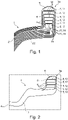
- Figs. 1 to 4 different exemplary embodiments of the rim body 2 can be seen.
- first rim flange region 3a is shown in these figures, but the second rim flange region 3b has the same structure as the first rim flange region 3a.
- the first rim flange area 3a is also formed by a plurality of fiber mat sections 14 arranged radially one above the other. These fiber mat sections 14 are part of a single fiber mat 11, as also shown in figure 5 is shown processed.
- the fiber mat 11 is wound up and turned inside out in such a way that the fiber mat sections 14 form the first rim flange area 3a and run to a radial inner side and to a common axial side towards the rim base area 4 and are connected to it.
- a fiber bundle 5 is arranged radially between the fiber mat sections 14 in the area of the first rim flange area 3a.
- a so-called single-row configuration can be seen in which only one fiber bundle 5 is wound up in the radial direction and forms a plurality of radially nested/radially stacked fiber bundle sections 12 . Accordingly, it is still preferred if the in 1 visible fiber bundle sections 12 arranged radially one above the other are formed by a single fiber bundle 5 .
- the fiber bundle 5 is fixed on the fiber mat 11 before the fiber mat 11 is wound up/the first rim flange region 3a is draped.
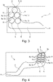
- the fiber bundle 5 is essentially rectangular and elliptical in the finished, hardened state of the rim body 2, with this cross-sectional shape also being able to deviate depending on the manufacturing process. This is under synopsis of Figs. 1 to 4 also clearly visible, wherein the fiber bundle or bundles 5 can also have wedge-shaped cross-sectional shapes.
- the radially outermost and the radially innermost fiber bundle section 12 can have a wedge shape describing the outer contour of the rim body 2 .
- Figs. 3 and 4 shows that several fiber bundles 5, characterized here as a first fiber bundle 5a and a second fiber bundle 5b, can be used in the first rim flange area 3a, which fiber bundles 5a, 5b are arranged axially next to each other on the respective fiber mat section 14 6 are arranged.
- the fiber bundles 5a, 5b thus form a plurality of radially nested rows with fiber bundle sections 12.
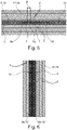
- Figs. 5 and 6 is the inventive compression wrapping 6 of the respective fiber bundle 5, as in the Figs. 1 to 4 is used alone or several times to recognize.
- the at least one fiber bundle 5 has the compression covering 6 .
- the compression wrap 6 is secured by a plurality of threads 7 that hold the fiber bundles 5 envelop, implemented.
- the threads 7 are wound around the fiber bundles 5 in such a way that they compress their individual threads in the radial direction.
- the compression covering 6 has at least two, here four, intersecting threads 7 which intersect regularly in the longitudinal direction of the fiber bundle 5 . In further embodiments, two, six or eight threads 7 are preferably used.
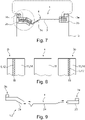
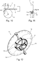
- the fiber bundle 5 is composed of several individual rovings, here eleven, which are twisted together in the longitudinal direction. Combined with 12 a corresponding wrapping method of the fiber bundle 5 is indicated in this regard.
- the fiber bundle 5 is fed centrally to a winding device 15 and is thereby wound up by the threads 7 wound up on movable spindle carriers 16 .
- the corresponding spindle carriers 16 are correspondingly prestressed for applying the compression.
- the rovings/fiber bundle 5 are made of carbon fiber in the present exemplary embodiments
- the threads 7 are made of glass fiber. However, other fibers can also be realized in other designs.
- the fiber bundle 5 is in accordance with the design figure 5 sewn onto the fiber mat 11.
- a seam is marked with the reference number 18 ( 8 ).
- the seam 18 is implemented as a zigzag seam or as a triple zigzag seam. In execution after 6 the two parallel fiber bundles 5a, 5b are also sewn onto the fiber mat 11.
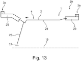
- the fiber mat 11 with the sewn-on fiber bundles 5 is of such a length that it is simply wound up several times, about three, four, five or six times, in order to Figs. 1 to 4 to form the first rim flange region 3a to be recognized.
- the protruding fiber mat sections 14 are, as already mentioned, simply further glued to the rim bed area 4 .
- the rim well area 4 is formed simply from a fiber mat 11 or from a plurality of fiber mats/fiber mat sections 14 placed one on top of the other.
- the fiber mat 11 is preferably implemented as an NCF mat, but can also be formed in other ways in further versions.
- the fiber mat 11 consists of a biaxial scrim (here +/-45° scrim) and is also made of carbon fiber.
- other fibers such as glass fibers or aramid fibers, are also used for the fiber mat 11 in further developments.
- the fiber bundles 5 are typically sewn onto the fiber mat 11.
- the fiber mat 11 is wound up several times together with the fiber bundles 5, with preference in the Figs. 10 and 11 recognizable take-up device 17 is used.
- the draping of the second rim flange area 3b takes place analogously to the draping of the first rim flange area 3a.
- the rim flange areas 3a and 3b are then connected to the rim base area 4 9 connected and consolidated to form the rim body 2.
- a binder powder is used to produce the rim body 2 / to connect the sub-preforms 23 , 24 , 25 .
- a resin is then added when the already assembled sub-preforms 23, 24, 25 (preform) are injected, with the implementation of an RTM injection.
- the binder powder then dissolves into the resin mixture during injection.
Landscapes
- Engineering & Computer Science (AREA)
- Mechanical Engineering (AREA)
- Chemical & Material Sciences (AREA)
- Composite Materials (AREA)
- Materials Engineering (AREA)
- Textile Engineering (AREA)
- Moulding By Coating Moulds (AREA)
Applications Claiming Priority (1)
| Application Number | Priority Date | Filing Date | Title |
|---|---|---|---|
| DE102020131243.1A DE102020131243A1 (de) | 2020-11-25 | 2020-11-25 | Fahrzeugfelge mit einem wenigstens ein Faserbündel aufweisenden Felgenkörper; Verfahren zu dessen Herstellung; sowie Fahrzeugrad |
Publications (3)
| Publication Number | Publication Date |
|---|---|
| EP4008564A1 true EP4008564A1 (fr) | 2022-06-08 |
| EP4008564B1 EP4008564B1 (fr) | 2023-09-06 |
| EP4008564C0 EP4008564C0 (fr) | 2023-09-06 |
Family
ID=78516484
Family Applications (1)
| Application Number | Title | Priority Date | Filing Date |
|---|---|---|---|
| EP21203073.8A Active EP4008564B1 (fr) | 2020-11-25 | 2021-10-18 | Jante de véhicule dotée d'un corps de jante comprenant au moins un faisceau de fibres, son procédé de fabrication, ainsi que roue de véhicule |
Country Status (3)
| Country | Link |
|---|---|
| US (1) | US20220161595A1 (fr) |
| EP (1) | EP4008564B1 (fr) |
| DE (1) | DE102020131243A1 (fr) |
Families Citing this family (4)
| Publication number | Priority date | Publication date | Assignee | Title |
|---|---|---|---|---|
| MX2023014781A (es) * | 2021-06-18 | 2024-03-19 | Carbon Revolution Ltd | Conector de refuerzo de cara a llanta de una rueda compuesta. |
| US20230114290A1 (en) * | 2021-10-12 | 2023-04-13 | Sram, Llc | Natural fiber composite bicycle component |
| TWI818394B (zh) * | 2021-12-27 | 2023-10-11 | 明安國際企業股份有限公司 | 輪框 |
| EP4698386A1 (fr) * | 2023-04-20 | 2026-02-25 | Carbon Revolution Pty Ltd | Architecture de fibre de jante d'une roue composite à performance améliorée |
Citations (3)
| Publication number | Priority date | Publication date | Assignee | Title |
|---|---|---|---|---|
| WO2015162173A1 (fr) * | 2014-04-23 | 2015-10-29 | Kringlan Composites Ag | Préforme de jante |
| WO2016128289A1 (fr) | 2015-02-11 | 2016-08-18 | Mubea Carbo Tech Gmbh | Procédé permettant de produire un corps annulaire renforcé par des fibres et dispositif permettant de produire un élément annulaire renforcé par des fibres |
| WO2019033169A1 (fr) * | 2017-08-18 | 2019-02-21 | Carbon Revolution Limited | Architecture de fibres de jante d'une roue composite |
Family Cites Families (7)
| Publication number | Priority date | Publication date | Assignee | Title |
|---|---|---|---|---|
| EP1506882B1 (fr) | 2003-08-11 | 2008-07-09 | Campagnolo Srl | Jante composite de bicyclette et procédé de sa fabrication |
| DE102006010445B4 (de) * | 2006-03-03 | 2014-02-13 | Denk Engineering Gmbh | Felge |
| US20090058180A1 (en) | 2007-08-29 | 2009-03-05 | Compositech, Inc. | Reinforced Composite Rim |
| US9550394B2 (en) * | 2013-03-27 | 2017-01-24 | Reynolds Cycling, Llc | Bicycle wheels with asymmetric carbon fiber rims |
| US9981500B2 (en) * | 2014-12-04 | 2018-05-29 | Enve Composites, Llc | Impact resistant rim |
| WO2016168834A1 (fr) * | 2015-04-17 | 2016-10-20 | Eve Wheels Llc | Ébauche de jante de roue composite et procédé de fabrication d'une ébauche de jante de roue composite |
| US11407253B2 (en) * | 2017-12-13 | 2022-08-09 | Falcon Composites Corp. | Bicycle rims and method of manufacture thereof |
-
2020
- 2020-11-25 DE DE102020131243.1A patent/DE102020131243A1/de active Pending
-
2021
- 2021-10-18 EP EP21203073.8A patent/EP4008564B1/fr active Active
- 2021-11-15 US US17/526,976 patent/US20220161595A1/en not_active Abandoned
Patent Citations (3)
| Publication number | Priority date | Publication date | Assignee | Title |
|---|---|---|---|---|
| WO2015162173A1 (fr) * | 2014-04-23 | 2015-10-29 | Kringlan Composites Ag | Préforme de jante |
| WO2016128289A1 (fr) | 2015-02-11 | 2016-08-18 | Mubea Carbo Tech Gmbh | Procédé permettant de produire un corps annulaire renforcé par des fibres et dispositif permettant de produire un élément annulaire renforcé par des fibres |
| WO2019033169A1 (fr) * | 2017-08-18 | 2019-02-21 | Carbon Revolution Limited | Architecture de fibres de jante d'une roue composite |
Also Published As
| Publication number | Publication date |
|---|---|
| EP4008564B1 (fr) | 2023-09-06 |
| DE102020131243A1 (de) | 2022-05-25 |
| EP4008564C0 (fr) | 2023-09-06 |
| US20220161595A1 (en) | 2022-05-26 |
Similar Documents
| Publication | Publication Date | Title |
|---|---|---|
| EP4008564B1 (fr) | Jante de véhicule dotée d'un corps de jante comprenant au moins un faisceau de fibres, son procédé de fabrication, ainsi que roue de véhicule | |
| DE102011087938B4 (de) | Radstern und Verfahren zur Herstellung eines Rades mit einem Radstern | |
| EP1985465B1 (fr) | Rayon, roue et procédé de fabrication d'un rayon, en particulier pour vélos | |
| EP2755862B1 (fr) | Roue de véhicule pourvue d'une jante en matière plastique renforcée par des fibres | |
| DE102010010513B4 (de) | Verfahren zur Herstellung von hohlprofilartigen Bauteilen aus Faserverbundwerkstoffen | |
| EP2361752B1 (fr) | Composant en composite de fibre et son procédé de fabrication | |
| EP2665600B1 (fr) | Procédé de fabrication d'un dispositif à fibres en forme de tube d'un élément composite renforcé par fibres et dispositif à fibres en forme de tube | |
| EP3587087A1 (fr) | Procédé de fabrication d'un récipient renforcé par des fibres | |
| EP2626218B1 (fr) | Procédé de fabrication d'une jante à base de matière première composite en fibres et jante pour un véhicule automobile | |
| EP3061593B1 (fr) | Roue de roulement de velo et procédé de fabrication | |
| EP3142843B1 (fr) | Procédé de production d'un tube d'amortisseur à partir d'un matériau composite renforcé par des fibres pour amortisseur de vibrations | |
| DE3239804A1 (de) | Verfahren zur herstellung eines gegenstands durch faserwickeln | |
| DE1188793B (de) | Verfahren und Hilfsmittel zur Herstellung eines druckfesten Kunststoffrohres | |
| DE1440200A1 (de) | Bau- oder Verbindungselemente fuer isolierende Konstruktionen,wie vornehmlich Isolatoren fuer Leitungen zum Transport elektrischer Energie oder von Mittelspannungsverteilungsnetzen | |
| DE3227138A1 (de) | Wulstkerne fuer luftreifen und ihre herstellung | |
| EP4297982B1 (fr) | Ensemble rayons en étoile fait d'une matière plastique renforcée par des fibres | |
| EP3974162A1 (fr) | Jante de véhicule pourvue de sous-préformes d'extrémité repliées ncf et son procédé de fabrication | |
| EP4272937A1 (fr) | Jante de véhicule comprenant une zone de bride formée d'au moins une sous-forme ; et procédé de fabrication d'un corps de jante | |
| WO2020169266A1 (fr) | Demi-produit tubulaire en matière fibreuse à tressage triaxial comportant des couches supplémentaires de fibres à délimitation locale | |
| DE102019101425B4 (de) | Verfahren zum Herstellen eines Felgenringes aus einem Faserverbundwerkstoff sowie Flechtkern zum Herstellen eines solchen Felgenringes | |
| DE102018125863A1 (de) | Verfahren zur Herstellung eines Faserverbund-Gelenkwellenrohres und Faserverbund-Gelenkwellenrohr | |
| DE2044995A1 (de) | Ringförmige Reifeneinlage fur Fahr zeugreifen | |
| DE102019006010A1 (de) | Faserverstärktes Strukturbauteil mit einer Kunststoffmatrix sowie Verfahren zu seiner Herstellung | |
| DE102019135794A1 (de) | Verfahren zum Herstellen einer Schraubenfeder aus einem Faser-Kunststoff-Verbundmaterial für Kraftfahrzeugaufhängungen mit progressiver Federkennlinie und Schraubenfeder | |
| DE19604275A1 (de) | Verfahren zur Herstellung eines Bauteils |
Legal Events
| Date | Code | Title | Description |
|---|---|---|---|
| PUAI | Public reference made under article 153(3) epc to a published international application that has entered the european phase |
Free format text: ORIGINAL CODE: 0009012 |
|
| STAA | Information on the status of an ep patent application or granted ep patent |
Free format text: STATUS: THE APPLICATION HAS BEEN PUBLISHED |
|
| AK | Designated contracting states |
Kind code of ref document: A1 Designated state(s): AL AT BE BG CH CY CZ DE DK EE ES FI FR GB GR HR HU IE IS IT LI LT LU LV MC MK MT NL NO PL PT RO RS SE SI SK SM TR |
|
| STAA | Information on the status of an ep patent application or granted ep patent |
Free format text: STATUS: REQUEST FOR EXAMINATION WAS MADE |
|
| 17P | Request for examination filed |
Effective date: 20220916 |
|
| RBV | Designated contracting states (corrected) |
Designated state(s): AL AT BE BG CH CY CZ DE DK EE ES FI FR GB GR HR HU IE IS IT LI LT LU LV MC MK MT NL NO PL PT RO RS SE SI SK SM TR |
|
| GRAP | Despatch of communication of intention to grant a patent |
Free format text: ORIGINAL CODE: EPIDOSNIGR1 |
|
| STAA | Information on the status of an ep patent application or granted ep patent |
Free format text: STATUS: GRANT OF PATENT IS INTENDED |
|
| RIC1 | Information provided on ipc code assigned before grant |
Ipc: B60B 21/10 20060101ALI20230210BHEP Ipc: B29C 70/86 20060101ALI20230210BHEP Ipc: B29C 70/30 20060101ALI20230210BHEP Ipc: B29C 70/20 20060101ALI20230210BHEP Ipc: B60B 21/00 20060101ALI20230210BHEP Ipc: B29C 70/28 20060101ALI20230210BHEP Ipc: B60B 5/02 20060101AFI20230210BHEP |
|
| INTG | Intention to grant announced |
Effective date: 20230322 |
|
| GRAS | Grant fee paid |
Free format text: ORIGINAL CODE: EPIDOSNIGR3 |
|
| GRAA | (expected) grant |
Free format text: ORIGINAL CODE: 0009210 |
|
| STAA | Information on the status of an ep patent application or granted ep patent |
Free format text: STATUS: THE PATENT HAS BEEN GRANTED |
|
| AK | Designated contracting states |
Kind code of ref document: B1 Designated state(s): AL AT BE BG CH CY CZ DE DK EE ES FI FR GB GR HR HU IE IS IT LI LT LU LV MC MK MT NL NO PL PT RO RS SE SI SK SM TR |
|
| REG | Reference to a national code |
Ref country code: GB Ref legal event code: FG4D Free format text: NOT ENGLISH |
|
| REG | Reference to a national code |
Ref country code: CH Ref legal event code: EP |
|
| REG | Reference to a national code |
Ref country code: DE Ref legal event code: R096 Ref document number: 502021001430 Country of ref document: DE |
|
| REG | Reference to a national code |
Ref country code: IE Ref legal event code: FG4D Free format text: LANGUAGE OF EP DOCUMENT: GERMAN |
|
| U01 | Request for unitary effect filed |
Effective date: 20230928 |
|
| U07 | Unitary effect registered |
Designated state(s): AT BE BG DE DK EE FI FR IT LT LU LV MT NL PT SE SI Effective date: 20231009 |
|
| PG25 | Lapsed in a contracting state [announced via postgrant information from national office to epo] |
Ref country code: GR Free format text: LAPSE BECAUSE OF FAILURE TO SUBMIT A TRANSLATION OF THE DESCRIPTION OR TO PAY THE FEE WITHIN THE PRESCRIBED TIME-LIMIT Effective date: 20231207 |
|
| PG25 | Lapsed in a contracting state [announced via postgrant information from national office to epo] |
Ref country code: RS Free format text: LAPSE BECAUSE OF FAILURE TO SUBMIT A TRANSLATION OF THE DESCRIPTION OR TO PAY THE FEE WITHIN THE PRESCRIBED TIME-LIMIT Effective date: 20230906 Ref country code: NO Free format text: LAPSE BECAUSE OF FAILURE TO SUBMIT A TRANSLATION OF THE DESCRIPTION OR TO PAY THE FEE WITHIN THE PRESCRIBED TIME-LIMIT Effective date: 20231206 Ref country code: HR Free format text: LAPSE BECAUSE OF FAILURE TO SUBMIT A TRANSLATION OF THE DESCRIPTION OR TO PAY THE FEE WITHIN THE PRESCRIBED TIME-LIMIT Effective date: 20230906 Ref country code: GR Free format text: LAPSE BECAUSE OF FAILURE TO SUBMIT A TRANSLATION OF THE DESCRIPTION OR TO PAY THE FEE WITHIN THE PRESCRIBED TIME-LIMIT Effective date: 20231207 |
|
| U20 | Renewal fee for the european patent with unitary effect paid |
Year of fee payment: 3 Effective date: 20231229 |
|
| PG25 | Lapsed in a contracting state [announced via postgrant information from national office to epo] |
Ref country code: IS Free format text: LAPSE BECAUSE OF FAILURE TO SUBMIT A TRANSLATION OF THE DESCRIPTION OR TO PAY THE FEE WITHIN THE PRESCRIBED TIME-LIMIT Effective date: 20240106 |
|
| PG25 | Lapsed in a contracting state [announced via postgrant information from national office to epo] |
Ref country code: ES Free format text: LAPSE BECAUSE OF FAILURE TO SUBMIT A TRANSLATION OF THE DESCRIPTION OR TO PAY THE FEE WITHIN THE PRESCRIBED TIME-LIMIT Effective date: 20230906 |
|
| PG25 | Lapsed in a contracting state [announced via postgrant information from national office to epo] |
Ref country code: SM Free format text: LAPSE BECAUSE OF FAILURE TO SUBMIT A TRANSLATION OF THE DESCRIPTION OR TO PAY THE FEE WITHIN THE PRESCRIBED TIME-LIMIT Effective date: 20230906 Ref country code: RO Free format text: LAPSE BECAUSE OF FAILURE TO SUBMIT A TRANSLATION OF THE DESCRIPTION OR TO PAY THE FEE WITHIN THE PRESCRIBED TIME-LIMIT Effective date: 20230906 Ref country code: IS Free format text: LAPSE BECAUSE OF FAILURE TO SUBMIT A TRANSLATION OF THE DESCRIPTION OR TO PAY THE FEE WITHIN THE PRESCRIBED TIME-LIMIT Effective date: 20240106 Ref country code: ES Free format text: LAPSE BECAUSE OF FAILURE TO SUBMIT A TRANSLATION OF THE DESCRIPTION OR TO PAY THE FEE WITHIN THE PRESCRIBED TIME-LIMIT Effective date: 20230906 Ref country code: CZ Free format text: LAPSE BECAUSE OF FAILURE TO SUBMIT A TRANSLATION OF THE DESCRIPTION OR TO PAY THE FEE WITHIN THE PRESCRIBED TIME-LIMIT Effective date: 20230906 Ref country code: SK Free format text: LAPSE BECAUSE OF FAILURE TO SUBMIT A TRANSLATION OF THE DESCRIPTION OR TO PAY THE FEE WITHIN THE PRESCRIBED TIME-LIMIT Effective date: 20230906 |
|
| PG25 | Lapsed in a contracting state [announced via postgrant information from national office to epo] |
Ref country code: PL Free format text: LAPSE BECAUSE OF FAILURE TO SUBMIT A TRANSLATION OF THE DESCRIPTION OR TO PAY THE FEE WITHIN THE PRESCRIBED TIME-LIMIT Effective date: 20230906 |
|
| REG | Reference to a national code |
Ref country code: DE Ref legal event code: R097 Ref document number: 502021001430 Country of ref document: DE |
|
| PG25 | Lapsed in a contracting state [announced via postgrant information from national office to epo] |
Ref country code: MC Free format text: LAPSE BECAUSE OF FAILURE TO SUBMIT A TRANSLATION OF THE DESCRIPTION OR TO PAY THE FEE WITHIN THE PRESCRIBED TIME-LIMIT Effective date: 20230906 |
|
| RAP2 | Party data changed (patent owner data changed or rights of a patent transferred) |
Owner name: ADVANCED INTERNATIONAL MULTITECH CO., LTD. |
|
| U1K | Transfer of rights of the unitary patent after the registration of the unitary effect |
Owner name: ADVANCED INTERNATIONAL MULTITECH CO., LTD.; TW |
|
| PLBE | No opposition filed within time limit |
Free format text: ORIGINAL CODE: 0009261 |
|
| STAA | Information on the status of an ep patent application or granted ep patent |
Free format text: STATUS: NO OPPOSITION FILED WITHIN TIME LIMIT |
|
| PG25 | Lapsed in a contracting state [announced via postgrant information from national office to epo] |
Ref country code: MC Free format text: LAPSE BECAUSE OF FAILURE TO SUBMIT A TRANSLATION OF THE DESCRIPTION OR TO PAY THE FEE WITHIN THE PRESCRIBED TIME-LIMIT Effective date: 20230906 |
|
| 26N | No opposition filed |
Effective date: 20240607 |
|
| U1N | Appointed representative for the unitary patent procedure changed after the registration of the unitary effect |
Representative=s name: STOECKELER, FERDINAND; DE |
|
| PG25 | Lapsed in a contracting state [announced via postgrant information from national office to epo] |
Ref country code: IE Free format text: LAPSE BECAUSE OF NON-PAYMENT OF DUE FEES Effective date: 20231018 |
|
| PG25 | Lapsed in a contracting state [announced via postgrant information from national office to epo] |
Ref country code: IE Free format text: LAPSE BECAUSE OF NON-PAYMENT OF DUE FEES Effective date: 20231018 |
|
| U20 | Renewal fee for the european patent with unitary effect paid |
Year of fee payment: 4 Effective date: 20241009 |
|
| PGFP | Annual fee paid to national office [announced via postgrant information from national office to epo] |
Ref country code: CH Payment date: 20241101 Year of fee payment: 4 |
|
| PG25 | Lapsed in a contracting state [announced via postgrant information from national office to epo] |
Ref country code: CY Free format text: LAPSE BECAUSE OF FAILURE TO SUBMIT A TRANSLATION OF THE DESCRIPTION OR TO PAY THE FEE WITHIN THE PRESCRIBED TIME-LIMIT; INVALID AB INITIO Effective date: 20211018 |
|
| U20 | Renewal fee for the european patent with unitary effect paid |
Year of fee payment: 5 Effective date: 20251014 |
|
| PG25 | Lapsed in a contracting state [announced via postgrant information from national office to epo] |
Ref country code: TR Free format text: LAPSE BECAUSE OF FAILURE TO SUBMIT A TRANSLATION OF THE DESCRIPTION OR TO PAY THE FEE WITHIN THE PRESCRIBED TIME-LIMIT Effective date: 20230906 |
|
| PGFP | Annual fee paid to national office [announced via postgrant information from national office to epo] |
Ref country code: GB Payment date: 20251009 Year of fee payment: 5 |
|
| PG25 | Lapsed in a contracting state [announced via postgrant information from national office to epo] |
Ref country code: HU Free format text: LAPSE BECAUSE OF FAILURE TO SUBMIT A TRANSLATION OF THE DESCRIPTION OR TO PAY THE FEE WITHIN THE PRESCRIBED TIME-LIMIT; INVALID AB INITIO Effective date: 20211018 |