EP4297982B1 - Ensemble rayons en étoile fait d'une matière plastique renforcée par des fibres - Google Patents
Ensemble rayons en étoile fait d'une matière plastique renforcée par des fibres Download PDFInfo
- Publication number
- EP4297982B1 EP4297982B1 EP22712798.2A EP22712798A EP4297982B1 EP 4297982 B1 EP4297982 B1 EP 4297982B1 EP 22712798 A EP22712798 A EP 22712798A EP 4297982 B1 EP4297982 B1 EP 4297982B1
- Authority
- EP
- European Patent Office
- Prior art keywords
- spoke
- spokes
- star
- hub
- rim
- Prior art date
- Legal status (The legal status is an assumption and is not a legal conclusion. Google has not performed a legal analysis and makes no representation as to the accuracy of the status listed.)
- Active
Links
Images


Classifications
-
- B—PERFORMING OPERATIONS; TRANSPORTING
- B60—VEHICLES IN GENERAL
- B60B—VEHICLE WHEELS; CASTORS; AXLES FOR WHEELS OR CASTORS; INCREASING WHEEL ADHESION
- B60B1/00—Spoked wheels; Spokes thereof
- B60B1/02—Wheels with wire or other tension spokes
- B60B1/04—Attaching spokes to rim or hub
- B60B1/043—Attaching spokes to rim
-
- B—PERFORMING OPERATIONS; TRANSPORTING
- B60—VEHICLES IN GENERAL
- B60B—VEHICLE WHEELS; CASTORS; AXLES FOR WHEELS OR CASTORS; INCREASING WHEEL ADHESION
- B60B1/00—Spoked wheels; Spokes thereof
- B60B1/003—Spoked wheels; Spokes thereof specially adapted for bicycles
-
- B—PERFORMING OPERATIONS; TRANSPORTING
- B60—VEHICLES IN GENERAL
- B60B—VEHICLE WHEELS; CASTORS; AXLES FOR WHEELS OR CASTORS; INCREASING WHEEL ADHESION
- B60B1/00—Spoked wheels; Spokes thereof
- B60B1/02—Wheels with wire or other tension spokes
- B60B1/04—Attaching spokes to rim or hub
- B60B1/043—Attaching spokes to rim
- B60B1/048—Attaching spokes to rim by the use of screws
-
- B—PERFORMING OPERATIONS; TRANSPORTING
- B60—VEHICLES IN GENERAL
- B60B—VEHICLE WHEELS; CASTORS; AXLES FOR WHEELS OR CASTORS; INCREASING WHEEL ADHESION
- B60B5/00—Wheels, spokes, disc bodies, rims, hubs, wholly or predominantly made of non-metallic material
- B60B5/02—Wheels, spokes, disc bodies, rims, hubs, wholly or predominantly made of non-metallic material made of synthetic material
-
- B—PERFORMING OPERATIONS; TRANSPORTING
- B60—VEHICLES IN GENERAL
- B60B—VEHICLE WHEELS; CASTORS; AXLES FOR WHEELS OR CASTORS; INCREASING WHEEL ADHESION
- B60B1/00—Spoked wheels; Spokes thereof
- B60B1/02—Wheels with wire or other tension spokes
- B60B1/04—Attaching spokes to rim or hub
- B60B1/043—Attaching spokes to rim
- B60B1/044—Attaching spokes to rim by the use of spoke nipples
-
- B—PERFORMING OPERATIONS; TRANSPORTING
- B60—VEHICLES IN GENERAL
- B60B—VEHICLE WHEELS; CASTORS; AXLES FOR WHEELS OR CASTORS; INCREASING WHEEL ADHESION
- B60B2360/00—Materials; Physical forms thereof
- B60B2360/30—Synthetic materials
- B60B2360/34—Reinforced plastics
- B60B2360/341—Reinforced plastics with fibres
-
- B—PERFORMING OPERATIONS; TRANSPORTING
- B60—VEHICLES IN GENERAL
- B60Y—INDEXING SCHEME RELATING TO ASPECTS CROSS-CUTTING VEHICLE TECHNOLOGY
- B60Y2200/00—Type of vehicle
- B60Y2200/10—Road Vehicles
- B60Y2200/13—Bicycles; Tricycles
Definitions
- the present invention relates to a spoke star made of a fiber-plastic composite, which is designed as a closed ring in star shape, wherein the spoke star has at least two spokes between a hub-side inner circumference of the spoke star and a rim-side outer circumference of the spoke star, wherein in the spoke star a single fiber bundle runs several times between the inner circumference and the outer circumference along spokes of the spoke star.
- a star is a roughly star-shaped structure whose rays are formed by spokes.
- a star has at least two spokes.
- Automotive rims made of fiber composite material are known in the art, modeled after cast rims. Their shape is given by fiber mats applied to a mold. The impregnated fiber mats are cured to produce the spoked wheel.
- a disadvantage of this state of the art is that preformed mold elements are required to give the rim its shape. Such molds are relatively complex to manufacture and accordingly expensive. Furthermore, they only allow the production of a specific type of spoked wheel in a specific size. Furthermore, the fiber utilization in the known solutions is not optimal.
- a generic spoke star is known from the DE102009020123A known.
- a method for producing a spoked star with one or more continuous fiber bundles using a manufacturing device is described.
- the manufacturing device has several Rim-side deflection devices and several hub-side deflection devices.
- a continuous fiber bundle is wound around at least a portion of the rim-side deflection devices, and a portion of the rim-side deflection devices is displaced toward the interior of the arrangement.
- the DE 94 16 688 U1 Describes hubs for attaching nipples to wheels with reversed spokes.
- the heads of uncranked spokes are secured to the rim, and the spokes are tensioned by nipples in the hub or another device on the hub.
- the rim-side end of a spoke made of fiber composite materials can be mounted in a slot parallel to the wheel plane, and the rim-side end can form a closed eyelet or one open toward the wheel axis. This eyelet contains a retaining pin that prevents the spoke from being pulled out due to tensile force.
- the DE 10 2007 026 782 A1 relates to a rim made of fiber composite material.
- the spoke end or individual spoke ends can be looped around a structural element of the rim, which can be, for example, a roving section, a stitching that engages the loop, and/or a pre-consolidated structural element.
- the spokes are made of a composite material and comprise a tapered tension body, the body having an intermediate section and two ends. The body is extended beyond each end by a fastening segment, the body and the fastening segments being connected by a transition region.
- the spoke has at least one section with a reinforced cross-section on the surface relative to the cross-section of the intermediate section, the section with a reinforced cross-section covering at least the transition region between the tension body and the built-in fastening segment.
- the Fastener can be applied as a sandwich between two layers of the rim and thus against the inner wall of the rim.
- the DE 10 2008 046 255 B3 describes a spoke made of carbon fibers for a bicycle wheel with an eyelet formed at at least one end, wherein the eyelet is divided into two separate opening areas by carbon fibers.
- a core made of material that is essentially incompressible with respect to the forces acting when the spokes are tensioned is inserted into each of the two opening areas.
- At the other end of the spoke there can be another eyelet with only one opening area.
- the opening area is semicircular on one side and tapered on the other side.
- a clamping block with an engagement element engages the eyelet and fixes it to the hub.
- the DE 10 2017 116 754 A1 describes a system wheel with spokes made of high-performance fiber materials.
- the spoke can be tensioned by means of at least one tensioning element, and the cross-section of the spoke is square-like in the untensioned state and essentially round in the tensioned state.
- the DE 10 2017 219 061 B4 relates to a vehicle wheel comprising a rim for receiving a tire of the wheel and a hub with spokes connecting the rim.
- the spokes consist of a spoke section made of an injection-molded thermoplastic material, into which at least one spoke reinforcement element is at least partially embedded, which consists at least partially of fiber-reinforced plastic.
- a loop of the reinforcement element, protruding from the spoke on the rim side, is guided radially outwardly around at least a portion of the rim reinforcement element.
- the EP 0 089 809 A1 describes a method for producing, by resin injection molding, fiber-reinforced articles from fibrous material bound in a curable matrix material.
- the articles comprise two or more spokes extending from a hub portion. Each spoke has the Loop shape.
- the fiber material is arranged so that at least as many rovings of the fiber material as there are spokes are arranged in continuous paths from the hub portion around each of the spokes. Each of the rovings overlaps each of the other rovings for at least part of its length.
- the DE 298 24 507 U1 relates to a composite spoke core for a wheel with spokes subjected to tensile stress.
- the composite spoke core comprises a continuous winding of a plurality of turns of fiber according to at least two parallel, straight sections, which are joined at their ends by two rounded sections.
- the straight sections can be joined to form a single strand.
- the core can have a fastening piece at each end for connection to the rim and the hub.
- the fastening piece consists of a bolt or a bolt section that engages the inner side of the continuous winding of the core.
- the EP 1 800 897 B1 describes a wheel comprising a rim, a hub, and at least one connection device of the rim to the hub.
- the connection device comprises a composite spoke and a first connection means of the spoke to the rim or the hub, wherein the spoke comprises an elongated body extending along a longitudinal direction between a first end and a second end.
- the body and the ends comprise fibers, wherein the fibers are arranged to form a first loop at the first end.
- the first connection means comprises a first insert arranged in the first loop, a first rod attached to the first insert, the first rod being aligned along the longitudinal direction, wherein a first screwing part or fastening part is defined on the first rod.
- the US 2008/0315675 A1 relates to a wheel comprising a rim, a hub, and at least one spoke connecting the rim to the hub.
- the spoke is made of a composite material, each spoke having a connecting element for detachably connecting the spoke to the hub.
- the connecting element is at least partially incorporated into the spoke by being molded together with the spoke.
- the connecting element may be a shouldered pin.
- the spoke may be a double spoke.
- the WO 1991/013771 A2 describes a non-rigid spoke comprising a central portion extending between a first and a second end, a first fastening means attached to a first end of the spoke, and a second fastening means arranged at the other end of the spoke.
- One of said fastening means may comprise an eye hook.
- the WO 2010/057857 A1 relates to a wheel, particularly for bicycles or motorcycles, comprising a rim having a polygonal cross-section, preferably a V-shape.
- the rim has, in its inner region, an arcuate insert or guide for supporting and sliding a complementarily shaped end of a spoke shaped like an open loop. The ends of the spoke can be inserted into correspondingly provided openings arranged in the rim in an area adjacent to the arcuate guide or insert.
- the DE 200 22 351 U1 discloses a composite spoke for a spoked wheel with an elongated central body and two attachment ends made of resin-embedded fibers.
- the fibers are arranged to form a loop at at least one of the attachment ends.
- the body has predetermined cross-sectional dimensions in a zone adjacent to the loop.
- the loop is formed around a thickening core enclosed within the loop such that the loop is filled and, at least locally, in a transverse direction, has a cross-sectional dimension larger than the dimension of the zone adjacent to the body.
- the present invention is based on the object of optimizing spoke stars made of fiber-plastic composite.
- a spoke star according to the preamble of claim 1 in that the two spokes of the double spokes are connected by a plastic matrix and the spoke arrangement within the spoke star is modeled on that of conventional wheels with steel spokes, wherein the spoke star is manufactured continuously as a closed ring of fiber composite material, wherein the spokes have a loop on the rim-side outer circumference of the spoke star and wherein the spokes have a loop on the hub-side inner circumference of the spoke star, wherein the loop on the hub-side inner circumference of the spoke star enables the spoke star to be fastened to bolts arranged on the hub.
- a fiber bundle is preferably a bundle of several continuous fibers, for example one or more rovings, which in particular have unidirectional fiber orientation, or a tape, a towpreg, an elongated prepreg, or an elongated scrim or fabric.
- a continuous fiber as is commonly used in fiber composite technology, is not actually infinitely long. In this patent application, a continuous fiber is defined as a fiber with the special property of being longer than a spoke. However, it is also conceivable to combine and use fibers that are shorter than a spoke to form a longer fiber bundle.
- a spoked star can, for example, be provided as part of a spoked wheel. It can serve to connect a hub to a rim.
- the spoked star preferably has an integer number of spokes.
- the spoked star preferably has rotationally symmetrical sections, in particular sections each comprising two spokes.
- a double spoke is formed by two parallel spokes.
- the spokes run approximately parallel from the hub-side inner circumference of the spoke star to the rim-side outer circumference of the spoke star.
- the loop on the rim-side outer circumference of the spoke star Fiber orientation reversed by 180°.
- the fibers in the two spokes of the double spoke run essentially parallel and oppositely directed.
- the spoke star according to the invention can be manufactured using the wet winding process.
- the fiber type and plastic matrix can be adapted to the requirements of the spoke star.
- the two spokes of the double spokes can be connected by the plastic matrix during the spoke star manufacturing process.
- the fibers in the spokes are arranged parallel.
- This arrangement of the fibers allows for optimal utilization of their stiffness and strength. This saves material in the production of the spoke spider, which also advantageously reduces the weight of the spoke spider.
- the goals of lightweight construction are thus achieved not only through the use of carbon fibers with a low specific weight, but also through the most efficient use of materials.
- the spoke star is constructed as a continuous, closed ring of fiber composite material.
- the spoke star has no open fiber bundles, allowing for better load transfer within the spoke star.
- the hub-side inner circumference of the spoke star and the rim-side outer circumference of the spoke star can have loops for connecting the spoke star to the hub or rim.
- These loops enable advantageous load transfer.
- the loops allow the spoke star to be attached to bolts located on the hub, eliminating the need for additional fastening elements and resulting in weight savings.
- the loops When designing the outer circumference of the spoke star on the rim side as loops, the loops preferably have half the diameter of the double spokes. This preferably reduces the tension while maintaining the same tensile force.
- the two spokes of the double spokes can be joined in such a way that the double spokes have the smallest cross-section in the direction of travel.
- the two spokes of the double spoke are arranged parallel and offset in the direction of travel.
- This arrangement of the spokes advantageously enables an aerodynamic shape.
- the shape of the double spoke can be advantageously modified by the cavity of the mold during the manufacturing process of the spoke star. This particularly advantageously allows the double spoke to be designed in an elliptical shape. This is particularly advantageous from an aerodynamic perspective.
- the spoke arrangement within the spoke star can be modeled on that of conventional wheels with steel spokes.
- the load transfer principles familiar from steel spokes can be used as a basis for this spoke arrangement.
- no new calculations, simulations, or tests on load transfer in the spokes are required.
- Experience with conventional rims can be used.
- the spoke star according to the invention advantageously simplifies assembly.
- Two identical spoke stars, twisted relative to each other, can be placed on the hub on each hub flange side.
- the spoke stars can be attached to the hub-side inner circumference of the spoke star using loops on hub bolts.
- the connection is preferably form-fitting.
- the rim-side outer circumference of the spoke star, with the loop located at the rim-side end of the double spokes, points directly towards the rim holes of the rim rim for fastening and tightening the spoke star to the rim rim.
- the radial and lateral runout as well as the centering of the spoked wheel can be adjusted by tightening the spoke star.
- the spoked star according to the invention enables a particularly simple and quick replacement of damaged spoked stars.
- a spoked star is damaged, only the spoked star can be replaced instead of the entire spoked wheel. This reduces repair costs and enables resource-efficient repair.
- a preferred embodiment of the invention is that at least one spoke has a fastening means on its loop.
- the fastener is used to attach the spoke star to the rim.
- the fastener can be inserted into the loop of the spoke star.
- the fastener can be detachably connected to the rim.
- fastening device can be connected to the loop in a form-fitting manner.
- connection between the spoke star and the fastener can be made with a form-fitting connection. Gluing the fastener is not necessary.
- fastening means can be fixed to a rim by means of a screw.
- the screw enables a particularly simple, quick, and secure connection of the fastener to the rim.
- the screw can be used to pre-tension the spoke star. By tightening the spoke star, the radial and lateral runout, as well as the centering of the spoked wheel, can be adjusted.
- the screw can be designed as a screw with a ball head.
- the loop can be bent slightly out of the plane.
- the loop is additionally secured in the fastener by the screw, providing a positive fit.
- the screw also prevents the loop from "jumping out” of the fastener.
- the fastener also prevents the loop from "pulling open.” This is achieved by the lateral support of the loop outlet provided by the fastener's "jaws.”
- a spoked wheel can be attached to a rim and a hub, forming a spoked wheel.
- the spoked wheel can be attached to the hub via loops on the spoked wheel, which are hooked into bolts on the hub.
- the spoked wheel can be attached to the rim using the fastening means according to the invention.
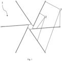
- FIGS 1 to 3 show schematically an embodiment of the spoke star 1 according to the invention.
- a single spoke star 1 is shown.
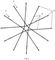
- Figure 2 is an arrangement of two spoke stars 1 made of Figure 1 The spoke stars 1 are rotated by 180° relative to each other. The arrangement can form one side of a spoked wheel.
- Figure 3 are two arrangements of Figure 2 The two arrangements are slightly twisted against each other and form the two sides of the spokes of a spoked wheel.
- the spoke star 1 consists of a fiber-plastic composite material.
- the spoke star 1 has spokes 2 between a hub-side inner circumference of the spoke star and a rim-side outer circumference of the spoke star.
- a single fiber bundle runs multiple times between the inner circumference and the outer circumference along spokes 2 of the spoke star.
- the spokes 2 are designed as double spokes.
- a double spoke is formed by two parallel spokes 2.
- the spokes 2 run approximately parallel from the hub-side inner circumference of the spoke star to the rim-side outer circumference of the spoke star.
- the spokes 2 have a loop 3 on the rim-side outer circumference of the spoke star.
- the loop 3 on the rim-side outer circumference of the spoke star reverses the fiber direction by 180°.
- the fibers in the two spokes 2 of the double spoke run essentially parallel and oppositely directed. Loops are provided on the hub-side inner circumference of the spoke star for a positive connection of the spoke star to a hub 7.
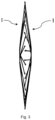
- Fig. 4 shows a detailed view of the rim-side outer circumference of a spoke star 1 according to the invention.
- the double spokes 2 have a loop 3 on the rim-side outer circumference of the spoke star.
- Loop 3 on the rim-side outer circumference of the spoke star reverses the fiber orientation by 180°.
- the fibers in the two spokes 2 of the double spoke run essentially parallel and oppositely directed.
- the loops 3 have half the diameter of the double spokes 2.
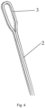
- Figure 5 is a detailed view of the hub-side inner circumference of the arrangement from Figure 2 shown.
- the loops on the hub-side inner circumference of the spoke star allow the spoke star to be connected in a form-fitting manner to a hub 7.
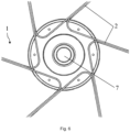
- Figure 6 is a detailed view of the hub-side inner circumference of the single spoke star 1 from Figure 1 shown.
- the loops on the hub-side inner circumference of the spoke star allow the spoke star to be connected in a form-fitting manner to a hub 7.
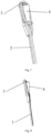
- FIGs 7 and 8 show a schematic representation of a spoke star 1 according to the invention with fastening means 4.
- the fastening means 4 is inserted into the loop 3 located on the rim-side outer circumference of the spoke star. In this way, the fastening means 4 is positively connected to the spoke star 1.
- the fastening means 4 can be connected to a rim 6 with a screw 5.
- the loop 3 is slightly bent out of the plane. This allows the loop 3 to be additionally secured in the fastening means 4 by a screw 5 when the spoke star 1 is mounted.
- the screw 5 advantageously prevents the loop 3 from "jumping out" of the fastening means 4.
- Fig. 9 is a representation of the spoke star1 with fastening means 4 from the Figures 7 and 8 shown in the mounted state on a rim 6.
- the fastening means 4 is fastened to the rim 6 with a screw 5.
- the screw 5 additionally prevents the loop 3 from jumping out of the Fastener 4 by positive locking.
- the screw 5 is aligned with the double spoke 2.
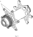
- FIGS 10 and 11 show schematically an embodiment of a hub 7 of a spoked wheel with a spoke star 1 according to the invention.
- the hub 7 has bolts 8 for the positive connection of the spoke star 1 with the hub 7, into which the loops 3 of the spoke star 1 engage.
- Fig. 11a and 11b show how first a first spoke star 1 is fastened by engagement of the bolts 8 in loops 3 on the hub-side inner circumference of the spoke star 1 and then - offset by 180° - a second spoke star 2.
Landscapes
- Engineering & Computer Science (AREA)
- Mechanical Engineering (AREA)
- Chemical & Material Sciences (AREA)
- Materials Engineering (AREA)
- Moulding By Coating Moulds (AREA)
Claims (6)
- Étoile à rayons (1) en un composite de fibres et de matière plastique, qui est réalisée sous la forme d'un anneau fermé en forme d'étoile, l'étoile à rayons (1) étant munie d'au moins deux rayons (2) entre une circonférence intérieure côté moyeu de l'étoile à rayons et une circonférence extérieure côté jante de l'étoile à rayons, un seul faisceau de fibres s'étendant plusieurs fois dans l'étoile à rayons entre la circonférence intérieure et la circonférence extérieure le long de rayons (2) de l'étoile à rayons, les rayons (2) étant réalisés sous la forme de rayons doubles,
caractérisée en ce que
les deux rayons (2) des rayons double sont reliés par une matrice en matière plastique, et la disposition des rayons à l'intérieur de l'étoile à rayons (1) est calquée sur celle des roues conventionnelles à rayons en acier, l'étoile à rayons (1) étant fabriquée de façon continue sous la forme d'un anneau fermé en matériau composite à base de fibres, les rayons (2) étant munis d'une boucle (3) sur la circonférence extérieure de l'étoile à rayons du côté de la jante, et les rayons (2) étant munis d'une boucle sur la circonférence intérieure de l'étoile à rayons du côté du moyeu, la boucle sur la circonférence intérieure de l'étoile à rayons du côté du moyeu permettant de fixer l'étoile à rayons à des boulons disposés sur le moyeu. - Étoile à rayons (1) selon la revendication 1, caractérisée en ce qu'au moins un rayon (2) est muni d'un moyen de fixation (4) au niveau de sa boucle (3).
- Étoile à rayons (1) selon la revendication 2, caractérisée en ce que le moyen de fixation (4) peut être relié par complémentarité de forme à la boucle (3).
- Étoile à rayons (1) selon l'une des revendications 2 ou 3, caractérisée en ce que le moyen de fixation (4) peut être fixé à une couronne de jante (6) au moyen d'une vis (5).
- Étoile à rayons (1) selon la revendication 4, caractérisée en ce que la vis (5) est alignée avec le rayon (2).
- Roue à rayons comprenant un moyeu (7), une couronne de jante (6) et plusieurs rayons (2) entre le moyeu (7) et la jante (6), caractérisée en ce que la roue à rayons comprend au moins une étoile à rayons (1) selon l'une des revendications précédentes.
Applications Claiming Priority (2)
| Application Number | Priority Date | Filing Date | Title |
|---|---|---|---|
| DE102021104740.4A DE102021104740A1 (de) | 2021-02-26 | 2021-02-26 | Speichenstern aus einem Faser-Kunststoff-Verbund |
| PCT/DE2022/100134 WO2022179662A1 (fr) | 2021-02-26 | 2022-02-21 | Ensemble rayons en étoile fait d'une matière plastique renforcée par des fibres |
Publications (3)
| Publication Number | Publication Date |
|---|---|
| EP4297982A1 EP4297982A1 (fr) | 2024-01-03 |
| EP4297982C0 EP4297982C0 (fr) | 2025-04-02 |
| EP4297982B1 true EP4297982B1 (fr) | 2025-04-02 |
Family
ID=80952453
Family Applications (1)
| Application Number | Title | Priority Date | Filing Date |
|---|---|---|---|
| EP22712798.2A Active EP4297982B1 (fr) | 2021-02-26 | 2022-02-21 | Ensemble rayons en étoile fait d'une matière plastique renforcée par des fibres |
Country Status (5)
| Country | Link |
|---|---|
| US (1) | US20240227432A9 (fr) |
| EP (1) | EP4297982B1 (fr) |
| CN (1) | CN116917138A (fr) |
| DE (1) | DE102021104740A1 (fr) |
| WO (1) | WO2022179662A1 (fr) |
Families Citing this family (1)
| Publication number | Priority date | Publication date | Assignee | Title |
|---|---|---|---|---|
| DE102022129154A1 (de) * | 2022-11-04 | 2024-05-08 | Munich Composites Gmbh | Felge für ein Kraftfahrzeug mit Felgenstern aus Faserverbundmaterial |
Citations (3)
| Publication number | Priority date | Publication date | Assignee | Title |
|---|---|---|---|---|
| DE102008046255B3 (de) * | 2008-09-08 | 2010-03-11 | Altek Gmbh | Speiche aus Karbonfasern für ein Fahrradlaufrad und Fahrradlaufrad mit einer Karbonspeiche |
| DE102017116754A1 (de) * | 2016-07-25 | 2018-01-25 | Ingo Berbig | Systemlaufrad mit Speichen auf Basis von Hochleistungsfaserstoffen |
| DE102018113797A1 (de) * | 2018-06-09 | 2019-12-12 | Institut Für Verbundwerkstoffe Gmbh | Herstellverfahren eines Speichensterns aus Endlosfaser-Kunststoff-Verbund |
Family Cites Families (24)
| Publication number | Priority date | Publication date | Assignee | Title |
|---|---|---|---|---|
| FR962372A (fr) * | 1950-06-09 | |||
| US657517A (en) * | 1900-01-17 | 1900-09-11 | Henry F Condon | Method of making vehicle-wheels. |
| EP0089809A1 (fr) | 1982-03-23 | 1983-09-28 | The British Petroleum Company p.l.c. | Méthode pour la fabrication d'objets renforcés de fibres |
| JPS59192601A (ja) * | 1983-04-15 | 1984-11-01 | Yamaha Motor Co Ltd | ワイヤスポ−ク車輪 |
| JPS61242833A (ja) * | 1985-04-19 | 1986-10-29 | Toyota Motor Corp | 繊維強化樹脂製デイスクホイ−ルの製造方法 |
| US5110190A (en) | 1990-03-16 | 1992-05-05 | Johnson Harold M | High modulus multifilament spokes and method |
| ATE118735T1 (de) * | 1990-07-25 | 1995-03-15 | Jiri Krampera | Felge für ein gespeichtes fahrrad-hinterrad. |
| DE9416688U1 (de) | 1994-10-18 | 1996-10-17 | Allmendinger, Eugen, Dipl.-Ing. (FH), 71711 Murr | Naben für die Befestigung von Nippeln im Nabenkörper bei Laufrädern mit umgekehrt eingebauten Speichen |
| DE29824507U1 (de) | 1997-04-16 | 2001-03-29 | Mavic (S.A.), Saint-Trivier-Sur-Moignans | Seele einer Speiche für ein Speichenrad, Speiche und Fahrradrad |
| FR2792251B1 (fr) * | 1999-04-16 | 2001-07-27 | Mavic Sa | Rayon realise en materiau composite pour une roue, et roue de bicyclette equipee desdits rayons |
| US6588853B2 (en) * | 2001-11-29 | 2003-07-08 | Shimano Inc. | Bicycle rim |
| FR2894873B1 (fr) | 2005-12-21 | 2008-04-18 | Salomon Sa | Roue comprenant une jante, un moyeu, et un dispositif de raccordement de la jante au moyeu |
| DE102007026782A1 (de) | 2006-06-25 | 2008-09-11 | Allmendinger, Eugen | Drahtreifenfelge aus Faserverbundwerkstoffen |
| DE102006051867A1 (de) * | 2006-10-31 | 2008-05-08 | Theuer, Arwed, Dr.-Ing. | Aus faserverstärktem Kunststoff gewickeltes Rad und Verfahren zu seiner Herstellung |
| FR2912345B1 (fr) | 2007-02-09 | 2009-05-08 | Salomon Sa | Rayon en matiere composite pour une roue a rayons. |
| FR2917666B1 (fr) * | 2007-06-25 | 2014-12-05 | Salomon Sa | Roue a rayon demontable en materiau composite |
| US20090033051A1 (en) * | 2007-07-31 | 2009-02-05 | Graco Children's Products Inc. | Stroller Wheel with Modular Suspension |
| IT1391976B1 (it) | 2008-11-18 | 2012-02-02 | Cicli Pinarello S P A | Struttura di ruota perfezionata |
| DE102009020123A1 (de) * | 2009-05-06 | 2010-11-11 | Golz, Günter | Vorrichtung zum Verbinden einer Nabe und einer Felge an einem Laufrad |
| DE102009050458B4 (de) * | 2009-10-23 | 2012-01-05 | Carbofibretec Gmbh | Fahrradlaufrad aus einem Verbundwerkstoff mit duroplastischem und thermoplastischem Harz sowie Fahrrad mit einem solchen Laufrad |
| DE102011087938B4 (de) * | 2011-12-07 | 2022-02-03 | Action Composites Hightech GmbH | Radstern und Verfahren zur Herstellung eines Rades mit einem Radstern |
| JP2016150615A (ja) * | 2015-02-16 | 2016-08-22 | 本田技研工業株式会社 | スポーク部製造方法 |
| DE102017219061B4 (de) | 2017-10-25 | 2019-06-27 | Ford Global Technologies, Llc | Radbauteil und Verfahren zum Herstellen eines Radbauteils |
| US20220080773A1 (en) * | 2018-12-31 | 2022-03-17 | Compagnie Generale Des Etablissements Michelin | Spoke for a non-pneumatic wheel |
-
2021
- 2021-02-26 DE DE102021104740.4A patent/DE102021104740A1/de not_active Ceased
-
2022
- 2022-02-21 US US18/277,508 patent/US20240227432A9/en active Pending
- 2022-02-21 WO PCT/DE2022/100134 patent/WO2022179662A1/fr not_active Ceased
- 2022-02-21 EP EP22712798.2A patent/EP4297982B1/fr active Active
- 2022-02-21 CN CN202280017123.9A patent/CN116917138A/zh active Pending
Patent Citations (3)
| Publication number | Priority date | Publication date | Assignee | Title |
|---|---|---|---|---|
| DE102008046255B3 (de) * | 2008-09-08 | 2010-03-11 | Altek Gmbh | Speiche aus Karbonfasern für ein Fahrradlaufrad und Fahrradlaufrad mit einer Karbonspeiche |
| DE102017116754A1 (de) * | 2016-07-25 | 2018-01-25 | Ingo Berbig | Systemlaufrad mit Speichen auf Basis von Hochleistungsfaserstoffen |
| DE102018113797A1 (de) * | 2018-06-09 | 2019-12-12 | Institut Für Verbundwerkstoffe Gmbh | Herstellverfahren eines Speichensterns aus Endlosfaser-Kunststoff-Verbund |
Also Published As
| Publication number | Publication date |
|---|---|
| EP4297982C0 (fr) | 2025-04-02 |
| CN116917138A (zh) | 2023-10-20 |
| US20240227432A9 (en) | 2024-07-11 |
| EP4297982A1 (fr) | 2024-01-03 |
| WO2022179662A1 (fr) | 2022-09-01 |
| DE102021104740A1 (de) | 2022-09-01 |
| US20240131861A1 (en) | 2024-04-25 |
Similar Documents
| Publication | Publication Date | Title |
|---|---|---|
| DE102011087938B4 (de) | Radstern und Verfahren zur Herstellung eines Rades mit einem Radstern | |
| EP1985465B1 (fr) | Rayon, roue et procédé de fabrication d'un rayon, en particulier pour vélos | |
| DE102008007722B4 (de) | Eingebettete Speiche aus Verbundmaterial für ein Speichenrad und Rad | |
| DE102006010445B4 (de) | Felge | |
| EP2755862B1 (fr) | Roue de véhicule pourvue d'une jante en matière plastique renforcée par des fibres | |
| EP2651751B1 (fr) | Élément modulaire de carrosserie et son procédé de fabrication | |
| DE102010050874B4 (de) | Kraftfahrzeugstrukturbauteil aus mittels eines Knotenelements verbundenen Halbzeug-Bauteilen und Herstellungsverfahren | |
| EP2511084B1 (fr) | Elément de noeud en matière plastique renforcée de fibres et procédé de fabrication et d'utilisation associé | |
| EP3041668B1 (fr) | Pièce composite pour un siège de véhicule et siège de véhicule correspondant | |
| DE102017219061B4 (de) | Radbauteil und Verfahren zum Herstellen eines Radbauteils | |
| EP2788173A1 (fr) | Roue réalisée en matériaux composites renforcés par fibres et procédé de fabrication | |
| DE102011077834A1 (de) | Verfahren zum Herstellen eines Faserverbund-Strukturteils, insbesondere Fahrzeug-Rades aus faserverstärktem Kunststoff | |
| EP1022164B1 (fr) | Dispositif d'attelage et crochet | |
| EP1607638B1 (fr) | Structure support utilisable dans le montage de carrosserie dans l'industrie automobile, et procédé pour la fabrication d'éléments d'une telle structure | |
| EP4008564B1 (fr) | Jante de véhicule dotée d'un corps de jante comprenant au moins un faisceau de fibres, son procédé de fabrication, ainsi que roue de véhicule | |
| EP4297982B1 (fr) | Ensemble rayons en étoile fait d'une matière plastique renforcée par des fibres | |
| EP3802150B1 (fr) | Procédé de fabrication d'une étoile à rayures en composite de fibres plastiques | |
| EP4197756A1 (fr) | Procédé de fabrication d'une jante, jante et dispositif outil | |
| DE29824507U1 (de) | Seele einer Speiche für ein Speichenrad, Speiche und Fahrradrad | |
| DE102019003260A1 (de) | Fahrradfelge und laufrad | |
| DE4416796A1 (de) | Radkörper | |
| DE102023117319B4 (de) | Felge mit einem Felgenbettbauteil, Felgenwänden und einem Rippenbauteil, sowie Laufrad und Herstellungsverfahren | |
| DE102022110699A1 (de) | Fahrzeugfelge mit einem aus mindestens einer Subpreform ausgebildetem Flanschbereich; und Verfahren zum Herstellen eines Felgenkörpers | |
| DE102024117759A1 (de) | Fahrradfelge mit Rippenbauteil beabstandet zu Felgenwänden, Laufrad und Herstellverfahren für Laufrad |
Legal Events
| Date | Code | Title | Description |
|---|---|---|---|
| STAA | Information on the status of an ep patent application or granted ep patent |
Free format text: STATUS: UNKNOWN |
|
| STAA | Information on the status of an ep patent application or granted ep patent |
Free format text: STATUS: THE INTERNATIONAL PUBLICATION HAS BEEN MADE |
|
| PUAI | Public reference made under article 153(3) epc to a published international application that has entered the european phase |
Free format text: ORIGINAL CODE: 0009012 |
|
| STAA | Information on the status of an ep patent application or granted ep patent |
Free format text: STATUS: REQUEST FOR EXAMINATION WAS MADE |
|
| 17P | Request for examination filed |
Effective date: 20230823 |
|
| AK | Designated contracting states |
Kind code of ref document: A1 Designated state(s): AL AT BE BG CH CY CZ DE DK EE ES FI FR GB GR HR HU IE IS IT LI LT LU LV MC MK MT NL NO PL PT RO RS SE SI SK SM TR |
|
| DAV | Request for validation of the european patent (deleted) | ||
| DAX | Request for extension of the european patent (deleted) | ||
| GRAP | Despatch of communication of intention to grant a patent |
Free format text: ORIGINAL CODE: EPIDOSNIGR1 |
|
| STAA | Information on the status of an ep patent application or granted ep patent |
Free format text: STATUS: GRANT OF PATENT IS INTENDED |
|
| INTG | Intention to grant announced |
Effective date: 20241004 |
|
| GRAS | Grant fee paid |
Free format text: ORIGINAL CODE: EPIDOSNIGR3 |
|
| GRAA | (expected) grant |
Free format text: ORIGINAL CODE: 0009210 |
|
| STAA | Information on the status of an ep patent application or granted ep patent |
Free format text: STATUS: THE PATENT HAS BEEN GRANTED |
|
| AK | Designated contracting states |
Kind code of ref document: B1 Designated state(s): AL AT BE BG CH CY CZ DE DK EE ES FI FR GB GR HR HU IE IS IT LI LT LU LV MC MK MT NL NO PL PT RO RS SE SI SK SM TR |
|
| REG | Reference to a national code |
Ref country code: GB Ref legal event code: FG4D Free format text: NOT ENGLISH |
|
| REG | Reference to a national code |
Ref country code: CH Ref legal event code: EP |
|
| REG | Reference to a national code |
Ref country code: IE Ref legal event code: FG4D Free format text: LANGUAGE OF EP DOCUMENT: GERMAN |
|
| REG | Reference to a national code |
Ref country code: DE Ref legal event code: R096 Ref document number: 502022003439 Country of ref document: DE |
|
| U01 | Request for unitary effect filed |
Effective date: 20250404 |
|
| U07 | Unitary effect registered |
Designated state(s): AT BE BG DE DK EE FI FR IT LT LU LV MT NL PT RO SE SI Effective date: 20250424 |
|
| PG25 | Lapsed in a contracting state [announced via postgrant information from national office to epo] |
Ref country code: ES Free format text: LAPSE BECAUSE OF FAILURE TO SUBMIT A TRANSLATION OF THE DESCRIPTION OR TO PAY THE FEE WITHIN THE PRESCRIBED TIME-LIMIT Effective date: 20250402 |
|
| PG25 | Lapsed in a contracting state [announced via postgrant information from national office to epo] |
Ref country code: GR Free format text: LAPSE BECAUSE OF FAILURE TO SUBMIT A TRANSLATION OF THE DESCRIPTION OR TO PAY THE FEE WITHIN THE PRESCRIBED TIME-LIMIT Effective date: 20250703 Ref country code: NO Free format text: LAPSE BECAUSE OF FAILURE TO SUBMIT A TRANSLATION OF THE DESCRIPTION OR TO PAY THE FEE WITHIN THE PRESCRIBED TIME-LIMIT Effective date: 20250702 |
|
| PG25 | Lapsed in a contracting state [announced via postgrant information from national office to epo] |
Ref country code: PL Free format text: LAPSE BECAUSE OF FAILURE TO SUBMIT A TRANSLATION OF THE DESCRIPTION OR TO PAY THE FEE WITHIN THE PRESCRIBED TIME-LIMIT Effective date: 20250402 |
|
| PG25 | Lapsed in a contracting state [announced via postgrant information from national office to epo] |
Ref country code: HR Free format text: LAPSE BECAUSE OF FAILURE TO SUBMIT A TRANSLATION OF THE DESCRIPTION OR TO PAY THE FEE WITHIN THE PRESCRIBED TIME-LIMIT Effective date: 20250402 |
|
| PG25 | Lapsed in a contracting state [announced via postgrant information from national office to epo] |
Ref country code: RS Free format text: LAPSE BECAUSE OF FAILURE TO SUBMIT A TRANSLATION OF THE DESCRIPTION OR TO PAY THE FEE WITHIN THE PRESCRIBED TIME-LIMIT Effective date: 20250702 |
|
| PG25 | Lapsed in a contracting state [announced via postgrant information from national office to epo] |
Ref country code: IS Free format text: LAPSE BECAUSE OF FAILURE TO SUBMIT A TRANSLATION OF THE DESCRIPTION OR TO PAY THE FEE WITHIN THE PRESCRIBED TIME-LIMIT Effective date: 20250802 |
|
| PG25 | Lapsed in a contracting state [announced via postgrant information from national office to epo] |
Ref country code: SM Free format text: LAPSE BECAUSE OF FAILURE TO SUBMIT A TRANSLATION OF THE DESCRIPTION OR TO PAY THE FEE WITHIN THE PRESCRIBED TIME-LIMIT Effective date: 20250402 |
|
| PG25 | Lapsed in a contracting state [announced via postgrant information from national office to epo] |
Ref country code: CZ Free format text: LAPSE BECAUSE OF FAILURE TO SUBMIT A TRANSLATION OF THE DESCRIPTION OR TO PAY THE FEE WITHIN THE PRESCRIBED TIME-LIMIT Effective date: 20250402 |
|
| PG25 | Lapsed in a contracting state [announced via postgrant information from national office to epo] |
Ref country code: SK Free format text: LAPSE BECAUSE OF FAILURE TO SUBMIT A TRANSLATION OF THE DESCRIPTION OR TO PAY THE FEE WITHIN THE PRESCRIBED TIME-LIMIT Effective date: 20250402 |
|
| PLBE | No opposition filed within time limit |
Free format text: ORIGINAL CODE: 0009261 |
|
| STAA | Information on the status of an ep patent application or granted ep patent |
Free format text: STATUS: NO OPPOSITION FILED WITHIN TIME LIMIT |
|
| REG | Reference to a national code |
Ref country code: CH Ref legal event code: L10 Free format text: ST27 STATUS EVENT CODE: U-0-0-L10-L00 (AS PROVIDED BY THE NATIONAL OFFICE) Effective date: 20260211 |
|
| 26N | No opposition filed |
Effective date: 20260105 |