EP4007710B1 - Display of an occupied and unoccupied seat in a vehicle for transporting passengers - Google Patents
Display of an occupied and unoccupied seat in a vehicle for transporting passengers Download PDFInfo
- Publication number
- EP4007710B1 EP4007710B1 EP20764015.2A EP20764015A EP4007710B1 EP 4007710 B1 EP4007710 B1 EP 4007710B1 EP 20764015 A EP20764015 A EP 20764015A EP 4007710 B1 EP4007710 B1 EP 4007710B1
- Authority
- EP
- European Patent Office
- Prior art keywords
- seat
- state
- lever
- occupied
- indication element
- Prior art date
- Legal status (The legal status is an assumption and is not a legal conclusion. Google has not performed a legal analysis and makes no representation as to the accuracy of the status listed.)
- Active
Links
- 238000000034 method Methods 0.000 claims description 5
- 238000001514 detection method Methods 0.000 description 5
- 238000010276 construction Methods 0.000 description 1
- 230000003137 locomotive effect Effects 0.000 description 1
- 239000000725 suspension Substances 0.000 description 1
Images


Classifications
-
- B—PERFORMING OPERATIONS; TRANSPORTING
- B60—VEHICLES IN GENERAL
- B60N—SEATS SPECIALLY ADAPTED FOR VEHICLES; VEHICLE PASSENGER ACCOMMODATION NOT OTHERWISE PROVIDED FOR
- B60N2/00—Seats specially adapted for vehicles; Arrangement or mounting of seats in vehicles
- B60N2/002—Seats provided with an occupancy detection means mounted therein or thereon
-
- B—PERFORMING OPERATIONS; TRANSPORTING
- B61—RAILWAYS
- B61D—BODY DETAILS OR KINDS OF RAILWAY VEHICLES
- B61D41/00—Indicators for reserved seats; Warning or like signs; Devices or arrangements in connection with tickets, e.g. ticket holders; Holders for cargo tickets or the like
- B61D41/04—Indicators for reserved seats
Definitions
- the invention relates to a device and a method for displaying the occupancy of a seat in a vehicle for passenger transport.
- WO 2014/044610 A1 It is known to use a sensor to determine the occupancy of a seat in a rail vehicle. An occupancy status of a set of seats in the rail vehicle is provided. To do this, a central unit detects data that represents the identification and position of a switch for the respective seat. Based on the data, the respective seat is marked as “occupied”.
- the US patent US 10,391,972 B1 describes a seat structure with a seat belt, in which a display element on the back of the seat back indicates whether a person occupying the seat has fastened or put on the seat belt.
- German patent application DE 10 2014 209 554 A1 describes a method for guiding a passenger to a passenger seat arranged in a vehicle. The occupancy status of passenger seats is determined and the passenger is directed to an unoccupied passenger seat.
- German patent application DE 10 2010 033 624 A1 describes a seat occupancy detection system for a motor vehicle with a plurality of motor vehicle seats.
- a detection means is arranged in each motor vehicle seat, which is set up and intended to detect whether the assigned motor vehicle seat is occupied by a person as intended.
- a control device for guiding people who enter the motor vehicle is set up and provided, in cooperation with the detection means, to indicate via a display means which the majority of motor vehicle seats are occupied as intended and/or are not occupied.
- the object of the invention is to increase the driving comfort for passengers of a vehicle for passenger transport and to improve the display of the occupancy of the seat in the vehicle.
- the device includes a display element which is arranged on the seat.
- the display element is designed to assume a first state in which the display element displays the seat as unoccupied.
- the display element is further designed to assume a second state in which the display element indicates the seat as occupied.
- the device further comprises a seat surface of the seat, which is intended to be occupied by a person or an object, and an operative connection between the seat surface and the display element, which is designed to cause the second state to be assumed when the seat is occupied.
- the invention recognized that passengers, when looking into a passenger compartment, in particular a so-called large compartment, are often unable to see which seats in the passenger compartment are occupied. On the one hand, this is because some of the seats face away from the passenger (in the direction of view). With this part of the seats, it is often not possible for the passenger to see whether a seat is occupied (as the seat back obscures the view). Even with seats that face the passenger (in the line of sight), it is often not possible for the passenger to see whether a seat is occupied by an object (e.g. a piece of luggage) or by a sleeping, slumped person (since other seats obscure the view). . So far it has been necessary for the passenger to walk through the passenger compartment in order to get free (ie not to look for occupied seats. Particularly in heavily utilized vehicles and due to the fact that passengers often carry luggage with them, finding free seats in existing vehicles is difficult.
- object e.g. a piece of luggage
- the solution according to the invention solves this problem in that the display element is put into the second state when the seat is occupied and shows the seat as occupied.
- the information about the current occupancy status can be mentally assigned to the seat simply by looking.
- a passenger looking for a free seat is thus able to determine which seats are occupied and which seats are free by taking a quick look into the passenger compartment.
- the passenger can quickly decide whether it is advisable to enter the passenger compartment or whether the passenger compartment can be passed through without taking a closer look or whether it can be left out when looking for a free seat. For example, the passenger may decide to continue the search in a different direction.
- indicating an occupied seat is to be understood to mean that an occupied seat (when the display element assumes the second state) and also an unoccupied seat (when the display element assumes the first state) can be identified.
- the vehicle for transporting people is preferably a vehicle for transporting people in local and/or long-distance public transport.
- the seat is preferably an elastic seat that lowers when the seat is occupied. More preferably, the elasticity is achieved by padding and/or suspension of the seat.
- the vehicle is a track-bound vehicle, in particular a double-decker train.
- the device according to the invention is particularly useful for track-bound vehicles, since the search for free seats in highly utilized track-bound vehicles represents a burden for passengers.
- passengers looking for a free seat have to carry their luggage through the vehicle's generally narrow aisles.
- Passengers who are already seated are also hindered by passengers looking for a free seat, for example when looking for a sanitary facility or an on-board restaurant.
- the device according to the invention is particularly advantageous in double-decker trains: after determining (by taking a quick look into the passenger compartment) that there is no free seat in a lower or upper passenger compartment, this passenger compartment can be left out and the search for a free seat in the upper or lower passenger compartment can be carried out . lower passenger compartment.
- double-decker train as a track-bound vehicle which is designed to be double-decker at least in some areas.
- it is a combination of a locomotive and several double-decker wagons.
- the double-decker train is, for example, a double-decker multiple unit.
- the display element is arranged on a seat back of the seat, in particular in the upper region of the seat back. This type of arrangement means that the display element is clearly visible, especially when you take a quick look over the seats in the passenger compartment.
- the active connection comprises a mechanical lever device. This represents a particularly simple and practical active connection.
- the lever device comprises a lever arm mounted on a pivot point.
- the pivot point is firmly connected to the seat.
- the lever arm is mounted on the pivot point in such a way that a first lever end of the lever arm is lowered when the seat is occupied and a second lever end of the lever arm is raised.
- the second lever end is connected to an arm element which is designed to move the display element into the second state when the second lever end is lifted. This can be implemented with particularly little effort in terms of construction.
- the arm element is preferably connected in an articulated manner to the second lever end.
- the arm element is connected in an articulated manner to the second lever end at a first arm end.
- the arm element is firmly connected to the display element at a second arm end.
- the active connection comprises an electronic, in particular data connection.
- the data connection can be a wireless connection and is preferably a wired connection.
- An occupation signal can be transmitted via the data connection. Depending on whether the occupancy signal represents an occupancy of the seat, the display element is set to the second state.
- a sensor element can be used to detect whether the seat is occupied. Depending on the detection of the sensor element, the occupancy of the seat is displayed using the display element. Preferably, an occupation signal is generated based on the detection of the sensor element, which is transmitted via the data connection is transmitted to the display element.
- the display element is designed as a displaceably mounted card element.
- This embodiment is particularly simple and practical.
- the map element is preferably colored reddish.
- the card element is mounted displaceably relative to the seat, in particular relative to the seat back.
- the display element protrudes visibly from the seat back of the seat at least in sections in the second state. In the first state, the display element is pushed into the seat back.
- the display element is an electronic display element.
- the display element lights up in the second state.
- the display element is a display element which displays occupancy information in the second state and does not display any occupancy information or information representing a free seat in the first state.
- the invention further relates to a seating device, comprising: a device of the type described above.
- the invention further relates to a track-bound vehicle, in particular a double-decker train, comprising: an arrangement of seating devices of the type described above.
- Figure 1 shows a track-bound vehicle 1 in a schematic side view with a device 10 according to the invention.
- the track-bound vehicle 1 is a rail vehicle 2, which is used to transport passengers 12, 14.
- the track-bound vehicle 1 has a passenger area 16, which is intended for the stay of the passengers 12 and 14.
- Several seating devices 18, in particular seats 19, are arranged within the passenger area 16.
- the seating devices 18 each have the device 10.
- the seat devices 18 each have a display element 20, which is arranged on the seat 19 in the upper region of the seat back 21.
- the display element 20 can have a first state 22 (see Figure 2 ), in which the seat 19 is displayed as unoccupied by means of the display element 20.
- the display element 20 can also have a second state 24 (see Figure 3 ), in which the seat 19 is displayed as occupied by the display element 20.
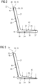
- Figure 2 shows one of the seat devices 18, in which the display element 20 is designed as a displaceably mounted card element 23 and assumes the first state 22.
- the seat 19 has a seat surface 26 which is intended to be occupied by a person (for example the passenger 14) and/or an object (not shown).
- the device 10 comprises an active connection 30 between the seat surface 26 and the display element 20.
- the active connection 30 is designed to cause the second state 24 to be assumed when the seat 19 is occupied.
- the active connection 30 is in the in Figure 2 shown first embodiment a mechanical lever device 32, which comprises a lever arm 36 mounted on a pivot point 34.
- the pivot point 34 is firmly connected to the seat 19.
- the lever arm 36 has a first lever end 37 and a second lever end 38. If the seat 19 is occupied and a force 42 is exerted on the seat surface 26, this leads to a lowering of the first lever end 37. Due to the storage on the pivot point 34, the second lever end 38 is raised when the first lever end 37 is lowered.
- the second lever end 38 is connected in an articulated manner to an arm element 44.
- the arm element 44 is connected in an articulated manner to the second lever end 38 at a first arm end 45.
- the arm element 44 is firmly connected to the display element 20 at a second arm end 46.
- Figure 3 shows the display element 20 in the second state 24, in which it is pushed out or pushed out of the upper opening 48.
- Figure 4 shows a front view of the seat 19, which is occupied by the passenger 14 and in which the display element 20 assumes the second state 24.
- FIG. 5 shows a second exemplary embodiment of a seat device 118 in a second state 24.
- a sensor element 136 detects whether the seat surface 26 is occupied.
- an occupation signal 150 is transmitted to the display element 120.
- the display element 120 is set to the second state 24.
- the display element 120 is an electronic display element which, for example, lights up in the second state 24 and does not light up in the first state 22.
- the display element 120 may be a display element which displays occupancy information in the second state 24 and does not display occupancy information or information representing a free seat in the first state 22.
Landscapes
- Engineering & Computer Science (AREA)
- Transportation (AREA)
- Mechanical Engineering (AREA)
- Aviation & Aerospace Engineering (AREA)
- Seats For Vehicles (AREA)
Description
Die Erfindung betrifft eine Vorrichtung und ein Verfahren zum Anzeigen einer Besetzung eines Sitzes in einem Fahrzeug zur Personenbeförderung.The invention relates to a device and a method for displaying the occupancy of a seat in a vehicle for passenger transport.
Aus der
Das
Die deutsche Patentanmeldung
Die deutsche Patentanmeldung
Vor diesem Hintergrund ist es Aufgabe der Erfindung, den Fahrkomfort für Fahrgäste eines Fahrzeugs zur Personenbeförderung zu erhöhen und die Anzeige der Besetzung des Sitzes in dem Fahrzeug zu verbessern.Against this background, the object of the invention is to increase the driving comfort for passengers of a vehicle for passenger transport and to improve the display of the occupancy of the seat in the vehicle.
Diese Aufgabe wird durch eine Vorrichtung zum Anzeigen einer Besetzung eines Sitzes in einem Fahrzeug zur Personenbeförderung gelöst. Die Vorrichtung umfasst ein Anzeigeelement, welches an dem Sitz angeordnet ist. Das Anzeigeelement ist ausgebildet, einen ersten Zustand, in welchem das Anzeigeelement den Sitz als nicht-besetzt anzeigt, einzunehmen. Das Anzeigeelement ist weiter ausgebildet, einen zweiten Zustand, in welchem das Anzeigeelement den Sitz als besetzt anzeigt, einzunehmen. Die Vorrichtung umfasst weiter eine Sitzfläche des Sitzes, welche für eine Besetzung durch eine Person oder einen Gegenstand vorgesehen ist, und eine Wirkverbindung zwischen der Sitzfläche und dem Anzeigeelement, die ausgebildet ist, bei Besetzen des Sitzes ein Einnehmen des zweiten Zustands zu bewirken.This task is solved by a device for displaying the occupancy of a seat in a passenger transport vehicle. The device includes a display element which is arranged on the seat. The display element is designed to assume a first state in which the display element displays the seat as unoccupied. The display element is further designed to assume a second state in which the display element indicates the seat as occupied. The device further comprises a seat surface of the seat, which is intended to be occupied by a person or an object, and an operative connection between the seat surface and the display element, which is designed to cause the second state to be assumed when the seat is occupied.
Mit der Erfindung wurde erkannt, dass Fahrgäste bei einem Blick in einen Fahrgastraum, insbesondere einen sogenannten Großraum, häufig nicht in der Lage sind, zu erkennen, welche Sitze des Fahrgastraums belegt sind. Dies liegt zum einen daran, dass ein Teil der Sitze dem Fahrgast (in Blickrichtung) abgewandt ist. Bei diesem Teil der Sitze ist für den Fahrgast häufig nicht erkennbar, ob ein Sitz besetzt ist (da die Sitzlehne die Sicht verdeckt). Auch bei Sitzen, die dem Fahrgast (in Blickrichtung) zugewandt sind, ist für den Fahrgast häufig nicht erkennbar, ob ein Sitz durch einen Gegenstand (z.B. ein Gepäckstück) oder durch eine schlafende, zusammengesunkene Person besetzt ist (da andere Sitze die Sicht verdecken). Somit ist es bisher erforderlich, dass der Fahrgast durch den Fahrgastraum läuft, um freie (d.h. nicht besetzte) Sitze zu suchen. Insbesondere bei hoch ausgelasteten Fahrzeugen und aufgrund der Tatsache, dass Fahrgäste häufig Gepäck mit sich führen, ist die Suche nach freien Sitzplätzen bei bisherigen Fahrzeugen beschwerlich.The invention recognized that passengers, when looking into a passenger compartment, in particular a so-called large compartment, are often unable to see which seats in the passenger compartment are occupied. On the one hand, this is because some of the seats face away from the passenger (in the direction of view). With this part of the seats, it is often not possible for the passenger to see whether a seat is occupied (as the seat back obscures the view). Even with seats that face the passenger (in the line of sight), it is often not possible for the passenger to see whether a seat is occupied by an object (e.g. a piece of luggage) or by a sleeping, slumped person (since other seats obscure the view). . So far it has been necessary for the passenger to walk through the passenger compartment in order to get free (ie not to look for occupied seats. Particularly in heavily utilized vehicles and due to the fact that passengers often carry luggage with them, finding free seats in existing vehicles is difficult.
Die erfindungsgemäße Lösung behebt dieses Problem, indem das Anzeigeelement durch das Besetzen des Sitzes in den zweiten Zustand versetzt wird und den Sitz als besetzt anzeigt. Durch die Anordnung des Anzeigeelements an dem Sitz kann die Information über den aktuellen Besetzungszustand dem Sitz durch einfaches Hinsehen gedanklich zugeordnet werden. Ein Fahrgast, der einen freien Sitzplatz sucht, wird dadurch in die Lage versetzt, anhand eines kurzen Blicks in den Fahrgastraum zu ermitteln, welche Sitze belegt und welche Sitze frei sind. Auf dieser Basis kann der Fahrgast zügig entscheiden, ob ein Begehen des Fahrgastraums zweckmäßig ist oder ob der Fahrgastraum ohne nähere Betrachtung passiert oder bei der Suche nach einem freien Sitzplatz ausgelassen werden kann. Beispielsweise kann der Fahrgast entscheiden, die Suche in einer anderen Richtung fortzusetzen.The solution according to the invention solves this problem in that the display element is put into the second state when the seat is occupied and shows the seat as occupied. By arranging the display element on the seat, the information about the current occupancy status can be mentally assigned to the seat simply by looking. A passenger looking for a free seat is thus able to determine which seats are occupied and which seats are free by taking a quick look into the passenger compartment. On this basis, the passenger can quickly decide whether it is advisable to enter the passenger compartment or whether the passenger compartment can be passed through without taking a closer look or whether it can be left out when looking for a free seat. For example, the passenger may decide to continue the search in a different direction.
Die Formulierung "Anzeigen einer Besetzung eines Sitzes" ist dahingehend zu verstehen, dass ein besetzter Sitz (wenn das Anzeigeelement den zweiten Zustand einnimmt) und zudem ein nicht-besetzter Sitz (wenn das Anzeigeelement den ersten Zustand einnimmt) kenntlich gemacht werden kann.The phrase “indicating an occupied seat” is to be understood to mean that an occupied seat (when the display element assumes the second state) and also an unoccupied seat (when the display element assumes the first state) can be identified.
Das Fahrzeug zur Personenbeförderung ist vorzugsweise ein Fahrzeug zur Beförderung von Personen im öffentlichen Nah- und/oder Fernverkehr.The vehicle for transporting people is preferably a vehicle for transporting people in local and/or long-distance public transport.
Die Sitzfläche ist vorzugsweise eine elastische Sitzfläche, die sich bei einem Besetzen des Sitzplatzes absenkt. Weiter vorzugsweise wird die Elastizität durch eine Polsterung und/oder Federung der Sitzfläche erzielt.The seat is preferably an elastic seat that lowers when the seat is occupied. More preferably, the elasticity is achieved by padding and/or suspension of the seat.
Bei einer bevorzugten Ausführungsform der erfindungsgemäßen Vorrichtung ist das Fahrzeug ein spurgebundenes Fahrzeug, insbesondere ein Doppelstockzug.In a preferred embodiment of the device according to the invention, the vehicle is a track-bound vehicle, in particular a double-decker train.
Die erfindungsgemäße Vorrichtung ist insbesondere für spurgebundene Fahrzeuge besonders zweckmäßig, da die Suche nach freien Sitzplätzen bei hoch ausgelasteten spurgebundenen Fahrzeugen eine Belastung für Fahrgäste darstellt. Zum einen müssen die nach einem freien Sitzplatz suchenden Fahrgäste ihr Gepäck durch die in der Regel engen Gänge des Fahrzeugs tragen. Auch die bereits sitzenden Fahrgäste werden durch die nach einem freien Sitzplatz suchenden Fahrgäste behindert, beispielsweise beim Aufsuchen einer sanitären Anlage oder eines Bordrestaurants.The device according to the invention is particularly useful for track-bound vehicles, since the search for free seats in highly utilized track-bound vehicles represents a burden for passengers. On the one hand, passengers looking for a free seat have to carry their luggage through the vehicle's generally narrow aisles. Passengers who are already seated are also hindered by passengers looking for a free seat, for example when looking for a sanitary facility or an on-board restaurant.
Besonders vorteilhaft ist die erfindungsgemäße Vorrichtung zudem bei Doppelstockzügen: Nach der Feststellung (durch einen kurzen Blick in den Fahrgastraum), dass in einem unteren bzw. oberen Fahrgastraum kein Sitzplatz frei ist, kann dieser Fahrgastraum ausgelassen und die Suche nach einem freien Sitzplatz im oberen bzw. unteren Fahrgastraum fortgesetzt werden.The device according to the invention is particularly advantageous in double-decker trains: after determining (by taking a quick look into the passenger compartment) that there is no free seat in a lower or upper passenger compartment, this passenger compartment can be left out and the search for a free seat in the upper or lower passenger compartment can be carried out . lower passenger compartment.
Der Fachmann versteht den Begriff "Doppelstockzug" als ein spurgebundenes Fahrzeug, welches zumindest in einem Teilbereich doppelstöckig ausgebildet ist. Beispielsweise handelt es sich um einen Verbund aus einer Lok und mehreren Doppelstockwaggons. Alternativ ist der Doppelstockzug beispielsweise ein Doppelstocktriebzug.The person skilled in the art understands the term "double-decker train" as a track-bound vehicle which is designed to be double-decker at least in some areas. For example, it is a combination of a locomotive and several double-decker wagons. Alternatively, the double-decker train is, for example, a double-decker multiple unit.
Bei einer weiteren bevorzugten Ausführungsform der erfindungsgemäßen Vorrichtung ist das Anzeigeelement an einer Sitzlehne des Sitzes, insbesondere im oberen Bereich der Sitzlehne angeordnet. Durch diese Art der Anordnung ist das Anzeigeelement gut sichtbar, insbesondere bei einem kurzen Blick über die Sitze des Fahrgastraums hinweg.In a further preferred embodiment of the device according to the invention, the display element is arranged on a seat back of the seat, in particular in the upper region of the seat back. This type of arrangement means that the display element is clearly visible, especially when you take a quick look over the seats in the passenger compartment.
Gemäß der erfindungsgemäßen Vorrichtung umfasst die Wirkverbindung eine mechanische Hebelvorrichtung. Dies stellt eine besonders einfache und zweckmäßige Wirkverbindung dar.According to the device according to the invention, the active connection comprises a mechanical lever device. This represents a particularly simple and practical active connection.
Ferner umfasst die Hebelvorrichtung erfindungsgemäß einen auf einem Drehpunkt gelagerten Hebelarm. Der Drehpunkt ist fest mit dem Sitz verbunden. Der Hebelarm ist derart auf dem Drehpunkt gelagert, dass ein erstes Hebelende des Hebelarms bei einem Besetzen des Sitzes abgesenkt wird und ein zweites Hebelende des Hebelarms angehoben wird. Das zweite Hebelende ist mit einem Armelement verbunden, welches ausgebildet ist, das Anzeigeelement beim Anheben des zweiten Hebelendes in den zweiten Zustand zu bewegen. Dies ist konstruktiv besonders aufwandsarm realisierbar.Furthermore, according to the invention, the lever device comprises a lever arm mounted on a pivot point. The pivot point is firmly connected to the seat. The lever arm is mounted on the pivot point in such a way that a first lever end of the lever arm is lowered when the seat is occupied and a second lever end of the lever arm is raised. The second lever end is connected to an arm element which is designed to move the display element into the second state when the second lever end is lifted. This can be implemented with particularly little effort in terms of construction.
Das Armelement ist vorzugsweise gelenkig mit dem zweiten Hebelende verbunden. Insbesondere ist das Armelement an einem ersten Armende gelenkig mit dem zweiten Hebelende verbunden. Zudem ist das Armelement an einem zweiten Armende fest mit dem Anzeigeelement verbunden.The arm element is preferably connected in an articulated manner to the second lever end. In particular, the arm element is connected in an articulated manner to the second lever end at a first arm end. In addition, the arm element is firmly connected to the display element at a second arm end.
Bei einer alternativen bevorzugten Ausführungsform der erfindungsgemäßen Vorrichtung umfasst die Wirkverbindung eine elektronische, insbesondere datentechnische Verbindung.In an alternative preferred embodiment of the device according to the invention, the active connection comprises an electronic, in particular data connection.
Die datentechnische Verbindung kann eine drahtlose Verbindung sein und ist vorzugsweise eine drahtgebundene Verbindung. Über die datentechnische Verbindung kann ein Besetzungssignal übertragen werden. In Abhängigkeit davon, ob das Besetzungssignal eine Besetzung des Sitzes repräsentiert, wird das Anzeigeelement in den zweiten Zustand versetzt.The data connection can be a wireless connection and is preferably a wired connection. An occupation signal can be transmitted via the data connection. Depending on whether the occupancy signal represents an occupancy of the seat, the display element is set to the second state.
Nach einer bevorzugten Weiterbildung ist mittels eines Sensorelements erfassbar, ob die Sitzfläche besetzt ist. In Abhängigkeit der Erfassung des Sensorelements wird die Besetzung des Sitzes mittels des Anzeigeelements angezeigt. Vorzugsweise wird auf Basis der Erfassung des Sensorelements ein Besetzungssignal erzeugt, welches über die datentechnische Verbindung an das Anzeigeelement übertragen wird.According to a preferred development, a sensor element can be used to detect whether the seat is occupied. Depending on the detection of the sensor element, the occupancy of the seat is displayed using the display element. Preferably, an occupation signal is generated based on the detection of the sensor element, which is transmitted via the data connection is transmitted to the display element.
Nach einer weiteren bevorzugten Ausführungsform der erfindungsgemäßen Vorrichtung ist das Anzeigeelement als verschieblich gelagertes Kartenelement ausgebildet. Diese Ausführungsform ist besonders einfach und zweckmäßig. Das Kartenelement ist vorzugsweise rötlich gefärbt.According to a further preferred embodiment of the device according to the invention, the display element is designed as a displaceably mounted card element. This embodiment is particularly simple and practical. The map element is preferably colored reddish.
Vorzugsweise ist das Kartenelement relativ zum Sitz, insbesondere relativ zur Sitzlehne, verschieblich gelagert.Preferably, the card element is mounted displaceably relative to the seat, in particular relative to the seat back.
Bei einer bevorzugten Weiterbildung ragt das Anzeigeelement in dem zweiten Zustand zumindest abschnittsweise sichtbar aus der Sitzlehne des Sitzes heraus. In dem ersten Zustand ist das Anzeigeelement in die Sitzlehne eingeschoben.In a preferred development, the display element protrudes visibly from the seat back of the seat at least in sections in the second state. In the first state, the display element is pushed into the seat back.
Bei einer weiteren alternativen Ausführungsform der erfindungsgemäßen Vorrichtung ist das Anzeigeelement ein elektronisches Anzeigeelement.In a further alternative embodiment of the device according to the invention, the display element is an electronic display element.
Beispielsweise leuchtet das Anzeigeelement im zweiten Zustand. Vorzugsweise ist das Anzeigeelement ein Displayelement, welches in dem zweiten Zustand eine Besetzungsinformation anzeigt, und in dem ersten Zustand keine Besetzungsinformation oder eine Information, die einen freien Sitzplatz repräsentiert, anzeigt.For example, the display element lights up in the second state. Preferably, the display element is a display element which displays occupancy information in the second state and does not display any occupancy information or information representing a free seat in the first state.
Die Erfindung betrifft ferner eine Sitzvorrichtung, umfassend: eine Vorrichtung der vorstehend beschriebenen Art. Die Erfindung betrifft ferner ein spurgebundenes Fahrzeug, insbesondere einen Doppelstockzug, umfassend: eine Anordnung von Sitzvorrichtungen der vorstehend beschriebenen Art.The invention further relates to a seating device, comprising: a device of the type described above. The invention further relates to a track-bound vehicle, in particular a double-decker train, comprising: an arrangement of seating devices of the type described above.
Die Erfindung betrifft ferner ein Verfahren zum Anzeigen einer Besetzung eines Sitzes in einem Fahrzeug zur Personenbeförderung, wobei ein Anzeigeelement an dem Sitz angeordnet ist, umfassend:
- Einnehmen eines ersten Zustands, in welchem das Anzeigeelement einen nicht-besetzten Sitz anzeigt,
- Besetzen einer Sitzfläche des Sitzes durch eine Person oder einen Gegenstand, und
- Einnehmen eines zweiten Zustands, in welchem das Anzeigeelement den Sitz als besetzt anzeigt,
- Assuming a first state in which the display element indicates an unoccupied seat,
- Occupying a seat surface of the seat by a person or an object, and
- Assuming a second state in which the display element shows the seat as occupied,
Zu Vorteilen, Ausführungsformen und Ausführungsdetails der Merkmale der erfindungsgemäßen Sitzvorrichtung, des erfindungsgemäßen spurgebundenen Fahrzeugs und des erfindungsgemäßen Verfahrens kann auf die obige Beschreibung zu den entsprechenden Merkmalen der erfindungsgemäßen Vorrichtung verwiesen werden.For advantages, embodiments and implementation details of the features of the seat device according to the invention, the track-bound vehicle according to the invention and the method according to the invention, reference can be made to the above description of the corresponding features of the device according to the invention.
Ausführungsbeispiele der Erfindung werden im Folgenden anhand der Zeichnungen erläutert. Es zeigen:
- Figur 1
- eine schematische Seitenansicht eines ersten Ausführungsbeispiels eines spurgebundenen Fahrzeugs,
- Figur 2
- eine schematische Seitenansicht eines ersten Ausführungsbeispiels einer Sitzvorrichtung des in
Figur 1 gezeigten spurgebundenen Fahrzeugs, bei der ein Anzeigeelement einen ersten Zustand einnimmt, - Figur 3
- eine schematische Seitenansicht des in
Figur 1 gezeigten ersten Ausführungsbeispiels der Sitzvorrichtung, bei der das Anzeigeelement einen zweiten Zustand einnimmt, - Figur 4
- eine schematische Frontansicht der in den
Figuren 2 und 3 gezeigten Sitzvorrichtung, bei der das Anzeigeelement den zweiten Zustand einnimmt, und - Figur 5
- eine schematische Seitenansicht eines zweiten Ausführungsbeispiels einer Sitzvorrichtung, bei der ein Anzeigeelement einen zweiten Zustand einnimmt.
- Figure 1
- a schematic side view of a first exemplary embodiment of a track-bound vehicle,
- Figure 2
- a schematic side view of a first embodiment of a seat device in
Figure 1 track-bound vehicle shown, in which a display element assumes a first state, - Figure 3
- a schematic side view of the in
Figure 1 shown first embodiment of the seat device, in which the display element assumes a second state, - Figure 4
- a schematic front view of the in the
Figures 2 and 3 seat device shown the display element assumes the second state, and - Figure 5
- a schematic side view of a second embodiment of a seat device, in which a display element assumes a second state.
Das spurgebundene Fahrzeug 1 weist einen Fahrgastbereich 16 auf, welcher für den Aufenthalt der Fahrgäste 12 und 14 vorgesehen ist. Innerhalb des Fahrgastbereichs 16 sind mehrere Sitzvorrichtungen 18, insbesondere Sitze 19, angeordnet. Die Sitzvorrichtungen 18 weisen jeweils die Vorrichtung 10 auf.The track-bound vehicle 1 has a passenger area 16, which is intended for the stay of the
Die Sitzvorrichtungen 18 weisen jeweils ein Anzeigeelement 20 auf, welches an dem Sitz 19 nämlich im oberen Bereich der Sitzlehne 21 angeordnet ist. Das Anzeigeelement 20 kann einen ersten Zustand 22 (siehe
Der Sitz 19 weist eine Sitzfläche 26 auf, die für eine Besetzung durch eine Person (beispielsweise den Fahrgast 14) und/oder einen Gegenstand (nicht gezeigt) vorgesehen ist.The seat 19 has a
Die Vorrichtung 10 umfasst eine Wirkverbindung 30 zwischen der Sitzfläche 26 und dem Anzeigeelement 20. Die Wirkverbindung 30 ist ausgebildet, ein Einnehmen des zweiten Zustands 24 zu bewirken, wenn der Sitz 19 besetzt wird.The device 10 comprises an
Die Wirkverbindung 30 ist in dem in
Der Hebelarm 36 weist ein erstes Hebelende 37 und ein zweites Hebelende 38 auf. Wird der Sitz 19 besetzt und dabei eine Kraft 42 auf die Sitzfläche 26 ausgeübt, führt dies zu einem Absenken des ersten Hebelendes 37. Durch die Lagerung auf dem Drehpunkt 34 wird beim Absenken des ersten Hebelendes 37 das zweite Hebelende 38 angehoben.The
Das zweite Hebelende 38 ist gelenkig mit einem Armelement 44 verbunden. Insbesondere ist das Armelement 44 an einem ersten Armende 45 gelenkig mit dem zweiten Hebelende 38 verbunden. Zudem ist das Armelement 44 an einem zweiten Armende 46 fest mit dem Anzeigeelement 20 verbunden. Wenn sich das zweite Hebelende 38 anhebt, bewirkt dies, dass sich das Anzeigeelement 20 in den zweiten Zustand 24 bewegt. Dabei wird das Anzeigeelement 20 aus einer oberen Öffnung 48 des Sitzes 19, insbesondere der Sitzlehne 21, herausgeschoben bzw. herausgedrückt.The
Das Anzeigeelement 120 ist ein elektronisches Anzeigeelement, welches beispielsweise im zweiten Zustand 24 leuchtet und im ersten Zustand 22 nicht leuchtet. Alternativ kann das Anzeigeelement 120 ein Displayelement sein, welches in dem zweiten Zustand 24 eine Besetzungsinformation anzeigt, und in dem ersten Zustand 22 keine Besetzungsinformation oder eine Information, die einen freien Sitzplatz repräsentiert, anzeigt.The
Obwohl die Erfindung anhand von Ausführungsbeispielen detailliert dargestellt und beschrieben wurde, ist die Erfindung nicht auf die offenbarten Ausführungsbeispiele und die darin erläuterten konkreten Merkmalskombinationen beschränkt. Weitere Variationen der Erfindung können von einem Fachmann hieraus abgeleitet werden, ohne den Schutzumfang der beanspruchten Erfindung zu verlassen.Although the invention has been illustrated and described in detail using exemplary embodiments, the invention is not limited to the exemplary embodiments disclosed and the specific combinations of features explained therein. Further variations of the invention can be derived by one skilled in the art without departing from the scope of the claimed invention.
Claims (9)
- Apparatus for indicating an occupancy of a seat (19) in a vehicle (1) for passenger transport, comprising:- an indication element (20, 120), which is arranged on the seat (19) and which is embodiedo to adopt a first state (22), in which the indication element (20, 120) indicates the seat (19) as unoccupied, ando to adopt a second state (24), in which the indication element (20, 120) indicates the seat (19) as occupied,- a seat surface (26) of the seat (19), which is provided for occupancy by a person (14) or an object, and- an active connection (30, 130) between the seat surface (26) and the indication element (20, 120), which is embodied to cause the second state (24) to be adopted when the seat (19) is occupied, characterised in thatthe active connection (30) comprises a mechanical lever apparatus (32) and the lever apparatus (32) comprises a lever arm (36) mounted at a point of rotation (34) and the point of rotation (34) is permanently connected to the seat (19),wherein the lever arm (36) is mounted at the point of rotation (34) in such a manner that a first lever end (37) of the lever arm (36) is lowered when the seat (19) is occupied and a second lever end (38) of the lever arm (36) is raised, andwherein the second lever end (38) is connected to an arm element (44), which is embodied to move the indication element (20) into the second state (24) when the second lever end (38) is raised.
- Apparatus according to claim 1,
in which the vehicle is a rail-bound vehicle (1), in particular a double-deck train. - Apparatus according to claim 1 or 2,
in which the indication element (20, 120) is arranged on a backrest (21) of the seat (19), in particular in the upper region of the backrest (21). - Apparatus according to at least one of the preceding claims,
in which the indication element (20) is embodied as a displaceably mounted map element (23). - Apparatus according to claim 3 and 4,
in which the indication element (20) in the second state (24) protrudes out from the backrest (21) of the seat (19) in a visible manner, at least in sections, and in the first state (22) is slid into the backrest (21). - Apparatus according to at least one of the preceding claims 1 to 3,
in which the indication element (120) is an electronic indication element. - Seat apparatus, comprising: an apparatus according to one of claims 1 to 6.
- Rail-bound vehicle, in particular double-deck train,
comprising: an arrangement of seat apparatuses (18, 118) according to claim 7. - Method for indicating an occupancy of a seat (19) in a vehicle (1) for passenger transport, wherein an indication element (30) is arranged on the seat (19), comprising:- adopting of a first state (22), in which the indication element (20) indicates an unoccupied seat (19),- occupancy of a seat surface (26) of the seat (19) by a person (14) or an object, and- adopting of a second state (24), in which the indication element (20) indicates the seat (19) as occupied,wherein the adopting of the second state (24) is caused by means of an active connection (30, 130) between the seat surface and the indication element (20, 120), characterised in that the active connection (30) comprises a mechanical lever apparatus (32) and the lever apparatus (32) comprises a lever arm (36) mounted at a point of rotation (34) and the point of rotation (34) is permanently connected to the seat (19),wherein the lever arm (36) is mounted at the point of rotation (34) in such a manner that a first lever end (37) of the lever arm (36) is lowered when the seat (19) is occupied and a second lever end (38) of the lever arm (36) is raised, and wherein the second lever end (38) is connected to an arm element (44), which is embodied to move the indication element (20) into the second state (24) when the second lever end (38) is raised.
Applications Claiming Priority (2)
| Application Number | Priority Date | Filing Date | Title |
|---|---|---|---|
| DE102019213946.9A DE102019213946A1 (en) | 2019-09-12 | 2019-09-12 | Display of an occupied and unoccupied seat in a vehicle for passenger transport |
| PCT/EP2020/072595 WO2021047850A1 (en) | 2019-09-12 | 2020-08-12 | Display of an occupied and unoccupied seat in a vehicle for transporting passengers |
Publications (2)
| Publication Number | Publication Date |
|---|---|
| EP4007710A1 EP4007710A1 (en) | 2022-06-08 |
| EP4007710B1 true EP4007710B1 (en) | 2023-09-27 |
Family
ID=72266259
Family Applications (1)
| Application Number | Title | Priority Date | Filing Date |
|---|---|---|---|
| EP20764015.2A Active EP4007710B1 (en) | 2019-09-12 | 2020-08-12 | Display of an occupied and unoccupied seat in a vehicle for transporting passengers |
Country Status (4)
| Country | Link |
|---|---|
| EP (1) | EP4007710B1 (en) |
| DE (1) | DE102019213946A1 (en) |
| PT (1) | PT4007710T (en) |
| WO (1) | WO2021047850A1 (en) |
Family Cites Families (4)
| Publication number | Priority date | Publication date | Assignee | Title |
|---|---|---|---|---|
| DE102010033624A1 (en) * | 2010-08-06 | 2012-02-09 | Daimler Ag | Seat occupancy recognition system for omnibus, has control device for directing passengers to unoccupied seats based on cooperation of detecting unit with indicator unit |
| WO2014044610A1 (en) | 2012-09-18 | 2014-03-27 | Siemens Aktiengesellschaft | Sensor, sensor network, seat and method for the detection of train seat occupancies |
| DE102014209554A1 (en) * | 2014-05-20 | 2015-11-26 | Siemens Aktiengesellschaft | Management of passengers |
| US10391972B1 (en) * | 2018-04-18 | 2019-08-27 | The Boeing Company | Seat assembly, seatbelt security system, and method |
-
2019
- 2019-09-12 DE DE102019213946.9A patent/DE102019213946A1/en not_active Ceased
-
2020
- 2020-08-12 WO PCT/EP2020/072595 patent/WO2021047850A1/en unknown
- 2020-08-12 EP EP20764015.2A patent/EP4007710B1/en active Active
- 2020-08-12 PT PT207640152T patent/PT4007710T/en unknown
Also Published As
| Publication number | Publication date |
|---|---|
| EP4007710A1 (en) | 2022-06-08 |
| WO2021047850A1 (en) | 2021-03-18 |
| DE102019213946A1 (en) | 2021-03-18 |
| PT4007710T (en) | 2024-01-02 |
Similar Documents
| Publication | Publication Date | Title |
|---|---|---|
| DE102008018938B4 (en) | Rail car with seat occupancy indicator | |
| DE102016011737B4 (en) | Rail-bound axle assembly | |
| DE102007055091A1 (en) | Seat arrangement in an aircraft | |
| DE102008060747A1 (en) | Need seat for a motor vehicle | |
| DE69108642T2 (en) | Command console of a driver's cab of a locomotive for a high-speed train. | |
| DE102010033624A1 (en) | Seat occupancy recognition system for omnibus, has control device for directing passengers to unoccupied seats based on cooperation of detecting unit with indicator unit | |
| WO2014040892A2 (en) | Operating a rail vehicle by means of an etcs device | |
| WO2018046264A1 (en) | Method and device for determining the presence of at least one passenger in a vehicle | |
| EP4007710B1 (en) | Display of an occupied and unoccupied seat in a vehicle for transporting passengers | |
| EP2821310A1 (en) | Arrangement of a display device for electronic seat reservation display in a vehicle | |
| EP0541928A1 (en) | Locking device for holding freight in an aircraft | |
| DE19641521C1 (en) | Method of controlling railway marshalling track occupancy using automatic signalling systems especially for controlling entry into station | |
| EP3694761B1 (en) | Rail vehicle car with a display device for seats | |
| DE10148482A1 (en) | Electronic derailment detector | |
| DE19824012B4 (en) | Information system for vehicles | |
| EP0572811A1 (en) | Assistant driver seat for omnibus | |
| DE102011081851A1 (en) | System for informing e.g. older person of underground railway, has passenger occupancies for individual wagons of transport units at respective stops displayed before arrival of transport unit near respective stop | |
| AT12883U1 (en) | PASSENGER RAIL VEHICLE WITH VARIABLE INTERIOR FOR MOBILITY RESTRICTED PEOPLE | |
| DE102018004006A1 (en) | Method for operating a vehicle | |
| DE102004036280B4 (en) | A resting | |
| AT135384B (en) | Device for coupling railway vehicles. | |
| DE102010022685A1 (en) | Seat system i.e. passenger seat system, for passenger car, has front and rear seat units arranged one behind another in one position, collapsible in another position for forming single seat, and provided with backrest and cushion parts | |
| EP0995661B1 (en) | Car body of a railway vehicle | |
| WO2013044947A1 (en) | Method for operating a track-bound vehicle, track-bound vehicle and arrangement with such a vehicle | |
| DE102022001439A1 (en) | Method for determining the overall height of a vehicle |
Legal Events
| Date | Code | Title | Description |
|---|---|---|---|
| STAA | Information on the status of an ep patent application or granted ep patent |
Free format text: STATUS: UNKNOWN |
|
| STAA | Information on the status of an ep patent application or granted ep patent |
Free format text: STATUS: THE INTERNATIONAL PUBLICATION HAS BEEN MADE |
|
| PUAI | Public reference made under article 153(3) epc to a published international application that has entered the european phase |
Free format text: ORIGINAL CODE: 0009012 |
|
| STAA | Information on the status of an ep patent application or granted ep patent |
Free format text: STATUS: REQUEST FOR EXAMINATION WAS MADE |
|
| 17P | Request for examination filed |
Effective date: 20220301 |
|
| AK | Designated contracting states |
Kind code of ref document: A1 Designated state(s): AL AT BE BG CH CY CZ DE DK EE ES FI FR GB GR HR HU IE IS IT LI LT LU LV MC MK MT NL NO PL PT RO RS SE SI SK SM TR |
|
| DAV | Request for validation of the european patent (deleted) | ||
| DAX | Request for extension of the european patent (deleted) | ||
| GRAP | Despatch of communication of intention to grant a patent |
Free format text: ORIGINAL CODE: EPIDOSNIGR1 |
|
| STAA | Information on the status of an ep patent application or granted ep patent |
Free format text: STATUS: GRANT OF PATENT IS INTENDED |
|
| INTG | Intention to grant announced |
Effective date: 20230322 |
|
| GRAS | Grant fee paid |
Free format text: ORIGINAL CODE: EPIDOSNIGR3 |
|
| GRAA | (expected) grant |
Free format text: ORIGINAL CODE: 0009210 |
|
| STAA | Information on the status of an ep patent application or granted ep patent |
Free format text: STATUS: THE PATENT HAS BEEN GRANTED |
|
| AK | Designated contracting states |
Kind code of ref document: B1 Designated state(s): AL AT BE BG CH CY CZ DE DK EE ES FI FR GB GR HR HU IE IS IT LI LT LU LV MC MK MT NL NO PL PT RO RS SE SI SK SM TR |
|
| REG | Reference to a national code |
Ref country code: GB Ref legal event code: FG4D Free format text: NOT ENGLISH |
|
| REG | Reference to a national code |
Ref country code: CH Ref legal event code: EP |
|
| REG | Reference to a national code |
Ref country code: DE Ref legal event code: R096 Ref document number: 502020005431 Country of ref document: DE |
|
| REG | Reference to a national code |
Ref country code: IE Ref legal event code: FG4D Free format text: LANGUAGE OF EP DOCUMENT: GERMAN |
|
| REG | Reference to a national code |
Ref country code: PT Ref legal event code: SC4A Ref document number: 4007710 Country of ref document: PT Date of ref document: 20240102 Kind code of ref document: T Free format text: AVAILABILITY OF NATIONAL TRANSLATION Effective date: 20231221 |
|
| REG | Reference to a national code |
Ref country code: LT Ref legal event code: MG9D |
|
| PG25 | Lapsed in a contracting state [announced via postgrant information from national office to epo] |
Ref country code: GR Free format text: LAPSE BECAUSE OF FAILURE TO SUBMIT A TRANSLATION OF THE DESCRIPTION OR TO PAY THE FEE WITHIN THE PRESCRIBED TIME-LIMIT Effective date: 20231228 |
|
| PG25 | Lapsed in a contracting state [announced via postgrant information from national office to epo] |
Ref country code: SE Free format text: LAPSE BECAUSE OF FAILURE TO SUBMIT A TRANSLATION OF THE DESCRIPTION OR TO PAY THE FEE WITHIN THE PRESCRIBED TIME-LIMIT Effective date: 20230927 Ref country code: RS Free format text: LAPSE BECAUSE OF FAILURE TO SUBMIT A TRANSLATION OF THE DESCRIPTION OR TO PAY THE FEE WITHIN THE PRESCRIBED TIME-LIMIT Effective date: 20230927 Ref country code: NO Free format text: LAPSE BECAUSE OF FAILURE TO SUBMIT A TRANSLATION OF THE DESCRIPTION OR TO PAY THE FEE WITHIN THE PRESCRIBED TIME-LIMIT Effective date: 20231227 Ref country code: LV Free format text: LAPSE BECAUSE OF FAILURE TO SUBMIT A TRANSLATION OF THE DESCRIPTION OR TO PAY THE FEE WITHIN THE PRESCRIBED TIME-LIMIT Effective date: 20230927 Ref country code: LT Free format text: LAPSE BECAUSE OF FAILURE TO SUBMIT A TRANSLATION OF THE DESCRIPTION OR TO PAY THE FEE WITHIN THE PRESCRIBED TIME-LIMIT Effective date: 20230927 Ref country code: HR Free format text: LAPSE BECAUSE OF FAILURE TO SUBMIT A TRANSLATION OF THE DESCRIPTION OR TO PAY THE FEE WITHIN THE PRESCRIBED TIME-LIMIT Effective date: 20230927 Ref country code: GR Free format text: LAPSE BECAUSE OF FAILURE TO SUBMIT A TRANSLATION OF THE DESCRIPTION OR TO PAY THE FEE WITHIN THE PRESCRIBED TIME-LIMIT Effective date: 20231228 Ref country code: FI Free format text: LAPSE BECAUSE OF FAILURE TO SUBMIT A TRANSLATION OF THE DESCRIPTION OR TO PAY THE FEE WITHIN THE PRESCRIBED TIME-LIMIT Effective date: 20230927 |
|
| REG | Reference to a national code |
Ref country code: NL Ref legal event code: MP Effective date: 20230927 |
|
| PG25 | Lapsed in a contracting state [announced via postgrant information from national office to epo] |
Ref country code: NL Free format text: LAPSE BECAUSE OF FAILURE TO SUBMIT A TRANSLATION OF THE DESCRIPTION OR TO PAY THE FEE WITHIN THE PRESCRIBED TIME-LIMIT Effective date: 20230927 |
|
| PG25 | Lapsed in a contracting state [announced via postgrant information from national office to epo] |
Ref country code: IS Free format text: LAPSE BECAUSE OF FAILURE TO SUBMIT A TRANSLATION OF THE DESCRIPTION OR TO PAY THE FEE WITHIN THE PRESCRIBED TIME-LIMIT Effective date: 20240127 |
|
| PG25 | Lapsed in a contracting state [announced via postgrant information from national office to epo] |
Ref country code: ES Free format text: LAPSE BECAUSE OF FAILURE TO SUBMIT A TRANSLATION OF THE DESCRIPTION OR TO PAY THE FEE WITHIN THE PRESCRIBED TIME-LIMIT Effective date: 20230927 |
|
| PG25 | Lapsed in a contracting state [announced via postgrant information from national office to epo] |
Ref country code: SM Free format text: LAPSE BECAUSE OF FAILURE TO SUBMIT A TRANSLATION OF THE DESCRIPTION OR TO PAY THE FEE WITHIN THE PRESCRIBED TIME-LIMIT Effective date: 20230927 Ref country code: RO Free format text: LAPSE BECAUSE OF FAILURE TO SUBMIT A TRANSLATION OF THE DESCRIPTION OR TO PAY THE FEE WITHIN THE PRESCRIBED TIME-LIMIT Effective date: 20230927 Ref country code: IS Free format text: LAPSE BECAUSE OF FAILURE TO SUBMIT A TRANSLATION OF THE DESCRIPTION OR TO PAY THE FEE WITHIN THE PRESCRIBED TIME-LIMIT Effective date: 20240127 Ref country code: ES Free format text: LAPSE BECAUSE OF FAILURE TO SUBMIT A TRANSLATION OF THE DESCRIPTION OR TO PAY THE FEE WITHIN THE PRESCRIBED TIME-LIMIT Effective date: 20230927 Ref country code: EE Free format text: LAPSE BECAUSE OF FAILURE TO SUBMIT A TRANSLATION OF THE DESCRIPTION OR TO PAY THE FEE WITHIN THE PRESCRIBED TIME-LIMIT Effective date: 20230927 Ref country code: SK Free format text: LAPSE BECAUSE OF FAILURE TO SUBMIT A TRANSLATION OF THE DESCRIPTION OR TO PAY THE FEE WITHIN THE PRESCRIBED TIME-LIMIT Effective date: 20230927 |
|
| PG25 | Lapsed in a contracting state [announced via postgrant information from national office to epo] |
Ref country code: PL Free format text: LAPSE BECAUSE OF FAILURE TO SUBMIT A TRANSLATION OF THE DESCRIPTION OR TO PAY THE FEE WITHIN THE PRESCRIBED TIME-LIMIT Effective date: 20230927 Ref country code: IT Free format text: LAPSE BECAUSE OF FAILURE TO SUBMIT A TRANSLATION OF THE DESCRIPTION OR TO PAY THE FEE WITHIN THE PRESCRIBED TIME-LIMIT Effective date: 20230927 |
|
| REG | Reference to a national code |
Ref country code: DE Ref legal event code: R097 Ref document number: 502020005431 Country of ref document: DE |
|
| PG25 | Lapsed in a contracting state [announced via postgrant information from national office to epo] |
Ref country code: DK Free format text: LAPSE BECAUSE OF FAILURE TO SUBMIT A TRANSLATION OF THE DESCRIPTION OR TO PAY THE FEE WITHIN THE PRESCRIBED TIME-LIMIT Effective date: 20230927 |
|
| PG25 | Lapsed in a contracting state [announced via postgrant information from national office to epo] |
Ref country code: DK Free format text: LAPSE BECAUSE OF FAILURE TO SUBMIT A TRANSLATION OF THE DESCRIPTION OR TO PAY THE FEE WITHIN THE PRESCRIBED TIME-LIMIT Effective date: 20230927 |
|
| PLBE | No opposition filed within time limit |
Free format text: ORIGINAL CODE: 0009261 |
|
| STAA | Information on the status of an ep patent application or granted ep patent |
Free format text: STATUS: NO OPPOSITION FILED WITHIN TIME LIMIT |
|
| 26N | No opposition filed |
Effective date: 20240628 |