EP4007471A2 - Leckerkennungs- und verhinderungssystem - Google Patents
Leckerkennungs- und verhinderungssystem Download PDFInfo
- Publication number
- EP4007471A2 EP4007471A2 EP22163713.5A EP22163713A EP4007471A2 EP 4007471 A2 EP4007471 A2 EP 4007471A2 EP 22163713 A EP22163713 A EP 22163713A EP 4007471 A2 EP4007471 A2 EP 4007471A2
- Authority
- EP
- European Patent Office
- Prior art keywords
- fluid
- cooling
- leak
- detection wires
- detection
- Prior art date
- Legal status (The legal status is an assumption and is not a legal conclusion. Google has not performed a legal analysis and makes no representation as to the accuracy of the status listed.)
- Withdrawn
Links
Images


Classifications
-
- H—ELECTRICITY
- H05—ELECTRIC TECHNIQUES NOT OTHERWISE PROVIDED FOR
- H05K—PRINTED CIRCUITS; CASINGS OR CONSTRUCTIONAL DETAILS OF ELECTRIC APPARATUS; MANUFACTURE OF ASSEMBLAGES OF ELECTRICAL COMPONENTS
- H05K7/00—Constructional details common to different types of electric apparatus
- H05K7/20—Modifications to facilitate cooling, ventilating, or heating
- H05K7/20218—Modifications to facilitate cooling, ventilating, or heating using a liquid coolant without phase change in electronic enclosures
- H05K7/20272—Accessories for moving fluid, for expanding fluid, for connecting fluid conduits, for distributing fluid, for removing gas or for preventing leakage, e.g. pumps, tanks or manifolds
-
- G—PHYSICS
- G06—COMPUTING OR CALCULATING; COUNTING
- G06F—ELECTRIC DIGITAL DATA PROCESSING
- G06F1/00—Details not covered by groups G06F3/00 - G06F13/00 and G06F21/00
- G06F1/16—Constructional details or arrangements
- G06F1/20—Cooling means
- G06F1/206—Cooling means comprising thermal management
-
- G—PHYSICS
- G01—MEASURING; TESTING
- G01M—TESTING STATIC OR DYNAMIC BALANCE OF MACHINES OR STRUCTURES; TESTING OF STRUCTURES OR APPARATUS, NOT OTHERWISE PROVIDED FOR
- G01M3/00—Investigating fluid-tightness of structures
- G01M3/02—Investigating fluid-tightness of structures by using fluid or vacuum
- G01M3/04—Investigating fluid-tightness of structures by using fluid or vacuum by detecting the presence of fluid at the leakage point
- G01M3/16—Investigating fluid-tightness of structures by using fluid or vacuum by detecting the presence of fluid at the leakage point using electric detection means
- G01M3/165—Investigating fluid-tightness of structures by using fluid or vacuum by detecting the presence of fluid at the leakage point using electric detection means by means of cables or similar elongated devices, e.g. tapes
-
- H—ELECTRICITY
- H05—ELECTRIC TECHNIQUES NOT OTHERWISE PROVIDED FOR
- H05K—PRINTED CIRCUITS; CASINGS OR CONSTRUCTIONAL DETAILS OF ELECTRIC APPARATUS; MANUFACTURE OF ASSEMBLAGES OF ELECTRICAL COMPONENTS
- H05K7/00—Constructional details common to different types of electric apparatus
- H05K7/20—Modifications to facilitate cooling, ventilating, or heating
- H05K7/20218—Modifications to facilitate cooling, ventilating, or heating using a liquid coolant without phase change in electronic enclosures
- H05K7/20254—Cold plates transferring heat from heat source to coolant
-
- H—ELECTRICITY
- H05—ELECTRIC TECHNIQUES NOT OTHERWISE PROVIDED FOR
- H05K—PRINTED CIRCUITS; CASINGS OR CONSTRUCTIONAL DETAILS OF ELECTRIC APPARATUS; MANUFACTURE OF ASSEMBLAGES OF ELECTRICAL COMPONENTS
- H05K7/00—Constructional details common to different types of electric apparatus
- H05K7/20—Modifications to facilitate cooling, ventilating, or heating
- H05K7/20709—Modifications to facilitate cooling, ventilating, or heating for server racks or cabinets; for data centers, e.g. 19-inch computer racks
- H05K7/20763—Liquid cooling without phase change
- H05K7/20772—Liquid cooling without phase change within server blades for removing heat from heat source
-
- H—ELECTRICITY
- H05—ELECTRIC TECHNIQUES NOT OTHERWISE PROVIDED FOR
- H05K—PRINTED CIRCUITS; CASINGS OR CONSTRUCTIONAL DETAILS OF ELECTRIC APPARATUS; MANUFACTURE OF ASSEMBLAGES OF ELECTRICAL COMPONENTS
- H05K7/00—Constructional details common to different types of electric apparatus
- H05K7/20—Modifications to facilitate cooling, ventilating, or heating
- H05K7/20709—Modifications to facilitate cooling, ventilating, or heating for server racks or cabinets; for data centers, e.g. 19-inch computer racks
- H05K7/20763—Liquid cooling without phase change
- H05K7/20781—Liquid cooling without phase change within cabinets for removing heat from server blades
Definitions
- Embodiments of the present invention relate generally to server and electronic cooling systems. More particularly, embodiments of the invention relate to leak detection and prevention in server cooling systems.
- a leak prevention system includes: a liquid cooling device for a data center including a fluid area configured to receive a cooling fluid; at least one pair of detection wires disposed within the liquid cooling device and at least partially surrounding the fluid area of the liquid cooling device; and a sensor connected to the at least one pair of detection wires and configured to detect when the cooling fluid contacts the detection wires.
- the senor is a current sensor; and the liquid cooling device includes an upper frame and a lower frame, and the at least one pair of detection wires is disposed between the upper frame and the lower frame.
- the leak prevention system further includes an inner sealing pad and an outer sealing pad disposed between the upper frame and the lower frame and surrounding the fluid area of the liquid cooling device, and wherein the at least one pair of detection wires is disposed between the inner sealing pad and the outer sealing pad.
- the leak prevention system further includes an inner sealing pad and an outer sealing pad disposed between the upper frame and the lower frame and surrounding the fluid area of the liquid cooling device, and wherein the at least one pair of detection wires is disposed within the inner sealing pad or the outer sealing pad.
- the at least one pair of detection wires detect a leak from the fluid area before the leak passes beyond the liquid cooling device.
- a leak prevention system includes a cooling plate within a liquid cooled data center cooling system, the cooling plate including at least one fluid port configured to connect with a fluid hose to receive a cooling fluid; at least one pair of detection wires positioned at a junction of the fluid port and the fluid hose; and a sensor connected to the at least one pair of detection wires and configured to detect when the cooling fluid contacts the detection wires.
- the senor is a current sensor; and each fluid port has a plurality of barbs extending radially outward from an external surface of the fluid port, and the at least one pair of detection wires is positioned between the external surface of the fluid port and the fluid hose across at least one of the plurality of barbs.
- the senor and at least one pair of detection wires are configured to detect a leak within the junction of the fluid port and the fluid hose before the cooling fluid leaks beyond the junction.
- the leak prevention system further includes a clamp positioned at the junction of the fluid port and the fluid hose and securing the fluid hose around an external surface of the fluid port, and the at least one pair of detection wires is positioned between the external surface of the fluid port and the fluid hose and is held in place by the clamp.
- a leak resistant server cooling module includes a plurality of cooling plates within a server rack, each cooling plate configured to receive a cooling fluid within a fluid area; a pair of detection wires disposed within each cooling plate and at least partially surrounding the fluid area of each cooling plate; an electrical detection bus connecting each pair of detection wires to form a plurality of detection circuits; one or more sensors in communication with the detection wires via the electrical detection bus and configured to detect when the cooling fluid contacts the detection wires; and a controller in communication with the one or more sensors configured to identify a location of a leak when the cooling fluid contacts the detection wires.
- each cooling plate includes an upper frame and a lower frame, and the detection wires of each cooling plate are disposed between the upper frame and the lower frame.; and the one or more sensors are current sensors.
- the leak resistant server cooling module further includes a fluid distribution manifold having one or more fluid ports configured to connect with a fluid hose to receive the cooling fluid; and at least one pair of detection wires positioned at a junction of one of the fluid ports and the fluid hose.
- each fluid port has a plurality of barbs extending radially outward from an external surface of the fluid port, and the detection wires are positioned between the external surface of the fluid port and the fluid hose across at least one of the plurality of barbs; and the sensor and detection wires are configured to detect a leak within the junction of the fluid port and the fluid hose before the cooling fluid leaks beyond the junction.
- the leak resistant server cooling module further includes a clamp positioned at the junction of one of the fluid ports and the fluid hose, the clamp securing the fluid hose around an external surface of the fluid port, wherein the at least one pair of detection wires is positioned between the external surface of the fluid port and the fluid hose and is held in place by the clamp.
- the controller is further configured to generate a notification identifying the location of the leak when the cooling fluid contacts the detection wires.
- Coupled is used to indicate that two or more elements, which may or may not be in direct physical or electrical contact with each other, co-operate or interact with each other.
- Connected is used to indicate the establishment of communication between two or more elements that are coupled with each other.
- server client
- device is intended to refer generally to data processing systems rather than specifically to a particular form factor for the server, client, and/or device.
- Embodiments described herein provide for a solution for developing leak detection and prevention solutions for servers, IT hardware equipment or other electronics packages products.
- the present disclosure provides for a leak detection design that can precisely identify a leak location before damage to servers or IT hardware occurs.
- a leak detection design that can precisely identify a leak location before damage to servers or IT hardware occurs.
- the present disclosure provides for a leak detection design that can precisely identify a leak location before damage to servers or IT hardware occurs.
- the present disclosure provides for a leak detection design that can precisely identify a leak location before damage to servers or IT hardware occurs.
- the server liquid cooling leak detection system In data centers, there are many liquid-cooled servers connected in a cooling loop, and leaks may happen in any of the servers or locations within the cooling loop. Therefore, one problem solved by the present disclosure is to provide a design for the server liquid cooling leak detection system to provide actual leaking locations in any leaking incidents.
- the current leak detection design can be used on different liquid cooling components and devices, and the leak detection system accuracy in terms of the detailed leakage locations can
- Another challenge in leak detection and prevention systems is cost. Not only is the detection system hardware costly, but also the corresponding sensors and controls systems. If the leak detection system consumes a large portion of the cooling hardware cost budget, the solution may not be deployed successfully in an actual product. This is also one of the major challenges for deploying liquid-cooled systems at a large scale. In addition, high scalability and interoperability are critical features for leak detection solutions, since the solution may need to be used for different liquid cooling components used in server cooling modules.
- a leak detection and prevention system which enables leak detection before the leaking fluid causes damage to electronics (i.e. before a critical leak occurs).
- the solution can be integrated with a server system easily, in some embodiments, and does not require expensive hardware costs.
- the leak detection and prevention system can be co-fabricated with the cooling components or the cooling module, thus allowing it to be more easily deployed within a server system. This may enable the solution to be more easily accepted, and makes for more efficient deployment.
- the leak detection system includes several sections or components, including electrical detection wires, electrical circuits, and one or more sensors.
- the electrical detection wires may be integrated within the cooling units, such as the cold plates, cooling manifolds, fluid ports, etc.
- the electrical detection wires can be connected with the electrical wires which are directly connected to a DC power source, such as a DC voltage.
- the electrical detection wires may be partially connected to the electrical circuits, in some embodiments.
- the circuits can be an open circuit when there is no leakage, and the circuits can be closed by the fluid when any leak occurs.
- the corresponding leak electrical detection wires can be assembled with the sealing structures or in their own dedicated channels, in various embodiments.
- the closed circuit is formed, and therefore the leak is detected, before the leaking fluid exits the cooling system or any components within the system that may causing damage to the electronics. Thus, a critical leak is prevented.
- Electronics cooling is an important market, since it is a fundamental technology for new chips and electronics and it provides a basic thermal environment for proper design and operation. It is seen that thermal management is becoming more and more critical for high performance processors. As computing hardware and processors become more and more expensive, cooling reliability is critical to prevent any potential damage to expensive components.
- FIG. 1A shows a cross sectional side view of a leak detection and prevention system, according to an embodiment of the present disclosure.
- a side view of a cold plate 101 is presented, and the cold plate includes an upper frame 103 and a lower frame 105.
- a sealing structure 109 Between the upper frame 103 and lower frame 105 is a sealing structure 109, which includes a sealing notch 115 configured to receive one or more sealing pads 113.
- the electrical wires 107 can extend from outside the cold plate, and be connected with electrical detection wires 111 located within the sealing structure 109 between the upper frame 103 and the lower frame 105.
- a detailed wiring layout of the electrical wires 107 can be different depending on various factors, including the product design.
- the detection wires 111 can be located within the internal sealing structure or sealing pad.
- the sealing structure 109 and electrical detection wires 111 can provide fluid sealing and leak prevention and detection from any leaks that may happen between the upper frame 103 and the lower frame 105.
- the embodiment shown in Figure 1A shows a solution developed on a commonly used cold plate. In some embodiments, co-design of the cooling components may be required in order to successfully implement the leak detection and prevention system.
- Figure 1B shows a cross sectional top view of the leak detection and prevention system of Figure 1A , according to an embodiment of the present disclosure. It can be seen in this embodiment that there are two sealing pads/structures, including an inner sealing pad 117 and an outer sealing pad 119.
- the detection wires 111 are located within the inner sealing pad 117, and the detection wires at least partially surround an internal area of the cold plate along the upper, right, and left sides, in this embodiment.
- the detection wires 111 are each connected to the outer sealing pad 119, and then can extend to the exterior of the cold plate toward a sensor (shown in FIG. 3 , etc.).
- the detection wires 111 are assembled at the inner sealing pad 117 to ensure that once any leaked fluid flows into the inner sealing notch holding the inner sealing pad 117, the leaked fluid contacts the detection wires 111 and completes a closed circuit.
- the outer sealing pad 119 provides additional fluid sealing. This means that the leak is detected before any fluid flows out of the cold plate. In a cold plate design, since the upper frame and lower frame are two separate parts attached together, therefore the contacting layer may leak if no proper sealing is added. It can be seen that the design shown in Figures 1A-1B can detect a leak before any critical leak actually occurs, thus significantly improving system reliability.
- the detection circuit used can be any suitable type of cable, such as copper wire.
- Several features of the detection wires may include the following. There may be two portions of the electrical wires: one portion used for detection, and the other portion used as a common electrical wire for completing a closed circuit loop.
- the detection wires 111 can be integrated into the sealing structure, and they can be placed in several disconnected locations, which can be connected by fluid in leaking incidents. In some embodiments, integrating the detection wires 111 with the inner sealing pad 117 simplifies construction, as the same channel can be used to hold the inner sealing pad 117 and the detection wires 111.
- FIG. 2 shows a cross sectional top view of another leak detection and prevention system, according to an embodiment of the present disclosure.
- the detection wires 205 are located within their own channel in the cold plate 201 between the inner sealing pad 207 and the outer sealing pad 203.
- the inner sealing pad 207 provides a first level of sealing. If any potential leaking happens within the cold plate, the fluid may flow to through the ring formed by the inner sealing pad 207, and then to a detection channel holding the detection wires 205. Once the fluid flows into contact with the detection wires 205, the closed circuit will enable a sensor to trigger a leakage alarm.
- the outer sealing pad 203 provides an additional layer of protection past the detection wires 205. Since the main material of the cold plate 201 may be copper, proper isolation may need to be designed for the detection wires 205, and such isolation may provide additional leak protection, in some embodiments. However, by proper voltage design on the detection circuit, isolation may not be necessary in every instance.
- FIG. 3 shows another design of a leak detection and prevention system, according to an embodiment of the present disclosure.
- the leak detection and prevention system includes a cooling unit 301, such as a cold plate, that includes an upper frame 303 and a lower frame 305.
- the cooling unit 301 contains a fluid area 307, and both an inner sealing pad 311 and an outer sealing pad 313 surround the fluid area 307.
- the detection wires 309 in this embodiment are located within the same channel as the inner sealing pad 311, and are connected to a sensor 315, that is in turn connected to a power source, such as a DC source.
- the fluid area 307 is the designed working area for the cooling fluid of the cooling unit 301, and any fluid leaking out of this fluid area 307 will contact with the inner sealing pad 311 as well as the detection wires 309 in the same channel.
- the sensor 315 may be any type of sensor, such as a current sensor.
- the current sensor can be used as the leakage signal and used as an input to a controller, in some embodiments. In this embodiment, once fluid leaks beyond the fluid area 307 and contacts the detection wires 309, a closed circuit is formed for the sensor 315 with the DC source.
- Figure 4 shows a cross sectional side view of a leak detection system assembled on a barb and hose assembly, according to an embodiment of the present disclosure.
- the liquid cooling system includes a fluid port 403, which includes a number of barbs 407.
- the barbs 407 can be angled annular features extending radially outward from the external surface of the fluid port 403.
- a fluid hose 405 can be fit around one side of the fluid port 403 in order to provide a cooling fluid to the cooling system (i.e. the cold plate), and the barbs 407 can interact with and create a seal with the fluid hose 405.
- the detection wires 401 can be connected to a sensor 409 and a DC voltage for detecting a leak.
- the detection wires can also be positioned at a junction between the fluid port 403 and the fluid hose 405, and can pass across at least one of the barbs 407.
- the detection wires 401 are positioned between the external surface of the fluid port 403 and the fluid hose 405 and pass across two of the barbs 407, such that if fluid leaks past the first barb, the leak will be detected before it passes beyond the entire junction between the fluid port 403 and the fluid hose 405.
- the detection wires 401 can pass across fewer or more barbs, as long as they pass across at least one, but not all, of the barbs.
- the detection wires 401 can detect a leak within the junction of the fluid port 403 and the fluid hose 405 before cooling fluid can leak beyond the junction.
- the fluid port 403 can be a fluid port integrated with a fluid manifold or a cold plate, or any other component of a fluid-cooled system that may transmit or receive cooling fluid.
- the fluid port 403 can include any number of barbs 407 (frequently three, but some designs could include as few as two), and the barbs can have various different geometries, in some embodiments.
- the fluid port can have no barbs, and the fluid hose can be secured to the fluid port using a clamp. An example of such a design is described in more detail in reference to FIG. 6 .
- Figure 5 shows another design of a leak detection and prevention system with barbed fluid ports, according to an embodiment of the present disclosure.
- Figure 5 shows a cooling module including multiple cooling components, cold plate, hoses, and fluid barb.
- a cold plate 501 includes a fluid area 503 filled with a cooling fluid, and this fluid area 503 is configured to connect with two fluid hoses 515 via fluid ports 511.
- These fluid ports 511 include a number of barbs 513 that can engage with the fluid hoses 515 to secure the hoses 515 on the fluid ports 511.
- the detection wires 505 are located at the fluid area 503 (for example, as described in FIGS. 1A-3 ), and also at the barbed fluid ports 511 (for example, as described in FIG. 4 ).
- the detection wires 505 are then able to connect with a sensor 509 via an electrical connection 507.
- the corresponding detection circuits for the fluid ports 511 and cold plate 501 may be assembled in a parallel manner to ensure that any leakage may form a complete circuit.
- Figure 6 shows a cross sectional side view of a leak detection system assembled on a clamp and hose assembly, according to embodiments of the present disclosure.
- a fluid hose 603 can be secured around another fluid hose 601, or a fluid port of a fluid manifold or cold plate, by using a clamp 605 that can be tightened around the junction between the fluid hoses 601, 603.
- the detection wires can be located between the fluid hoses 601, 603, or located at some other position at the junction between the fluid hoses 601, 603, and held in place by the clamp 605.
- detection wires 607 can be integrated into the clamp 605 such that a leak at the junction between the fluid hoses 601, 603 will be detected by the sensor 609.
- fluid connection described in Figure 6 can be a fluid port integrated with a fluid manifold or a cold plate, or any other component of a fluid-cooled system that may transmit or receive cooling fluid.
- FIG. 7 shows a diagram of a server cooling module 701, according to embodiments of the present disclosure.
- the server cooling module 701 has several cold plates 703, and each cold plate can include a set of detection wires 705.
- the detection circuit for each cold plate 703 can be separate, as shown in this embodiment, and can then be connected to one main circuit with a DC source and a sensor 707. In this design, only one sensor 707 is used. This means the detection accuracy is on the server level, and any of leak among all of the cold plates 703 may trigger the alarm.
- the sensor 707 can identify the accurate leak locations through internal design.
- FIG. 8 shows a diagram of another server cooling module 801, according to embodiments of the present disclosure.
- the server cooling module 801 includes a fluid distribution manifolds 803 as well as a number of cold plates 805.
- each fluid manifold 803 can service a certain number of cold plates 805 via fluid lines 807.
- the detection wires 813 are shown as examples to represent an efficient system level leakage detection implementation, where detection wires 813 are located at each cold plate 805, and also at a number of fluid ports 809.
- the fluid ports 809 can be barbed fluid ports, as described in FIGS. 4-5 , in some embodiments.
- the server cooling module 801 also includes an electrical detection bus 811 that can connect each of the individual detection circuits formed by the detection wires 813. Using the electrical bus 811, the leak detection and prevention solution can be implemented to different cooling components within the cooling module 801. In this embodiment, all of the detection circuits can be connected to the electrical bus 811, which can be designed as a standard port on the cooling module. In some embodiments, the electrical bus 811 can also function as a port to connect with a server DC source, or other DC source.
- FIG. 9 shows a diagram of a multi-module server cooling system, according to embodiments of the present disclosure.
- two server cooling modules 901, 902 are shown, each with fluid manifolds 903, and cold plates 905 fluidly connected via fluid lines 907.
- the server cooling system also includes detection lines 913 that can be located at the cold plates 905 and at fluid ports 909 that may be located on either the fluid manifolds 903 or the cold plates 905.
- the detection lines 913 can be connected with a DC power source and a sensor 915 via electrical connections 911.
- this embodiment only shows two server cooling modules 901, 902, this design can be expanded to include any number of server cooling modules within a data center.
- the potential failure rate of the sensors may be decreased, and the overall design of the cooling system is simplified and made more efficient.
- the sensor 915 can be integrated with additional controls for further instructions after detecting a leak.
- the accuracy of the detection system from the sensor 915 can be understood as multiple systems, this means this accuracy is lower than the one illustrated in Figure 8 .
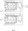
- FIG. 10 shows a diagram of another multi-module server cooling system, according to embodiments of the present disclosure.
- two server cooling modules 1001, 1003 include their own dedicated sensor 1005, 1007, which are each connected to a controller 1009.
- Each server cooling module 1001, 1003 can also include fluid manifolds, cold plates, fluid lines, fluid ports, detection wires, etc. as described above in FIGS. 1A-9 , in various embodiments.
- Connecting server cooling modules 1001, 1003 to a controller 1009 can enable additional features, such as allowing the sensors to provide leakage detection, and also allowing the controller 1009 to identify a corresponding module associated with the leak. In this way, the system can detect leaks early and also identify a location of the leak, thus additionally preventing critical leaks that may damage hardware.
- the controller 1009 can also generate a message or notification, in some embodiments, that can indicate the existence of, and in some cases the location of, a leak. In some embodiments, a different notification can be generated depending on the number of leaks detected, such that the severity of a leak can be indicated.
- each sensor 1005, 1007 shown in FIG. 10 is associated with a single server cooling module, one skilled in the art will appreciate that in other embodiments each of these sensors can be associated with a number of cooling modules, as described in reference to FIG. 9 .
- Various other customized arrangements of sensors, controllers, cooling modules, and cooling components are also envisioned by this disclosure and fall within the scope of this disclosure.
- the arrangement and implementation of the detection wires and/or electrical wires can be different for different objectives or cooling designs. These objectives and cooling designs can vary depending on the types of servers or IT hardware being cooled, in some embodiments.
- a leak prevention system includes a liquid cooling device for a data center including a fluid area configured to receive a cooling fluid.
- the system also includes at least one pair of detection wires disposed within the liquid cooling device and at least partially surrounding the fluid area of the liquid cooling device.
- the system also includes a sensor connected to the detection wires and configured to detect when the cooling fluid contacts the detection wires.
- the sensor is a current sensor.
- the liquid cooling device includes an upper frame and a lower frame, and the detection wires are disposed between the upper frame and the lower frame.
- the system also includes an inner sealing pad and an outer sealing pad disposed between the upper frame and the lower frame and surrounding the fluid area of the liquid cooling device.
- the detection wires are disposed between the inner sealing pad and the outer sealing pad. In another such embodiment, the detection wires are disposed within the inner sealing pad or the outer sealing pad. In one embodiment, the detection wires detect a leak from the fluid area before the leak passes beyond the liquid cooling device.
- a leak prevention system includes a cooling plate within a liquid cooled data center cooling system.
- the cooling plate includes a fluid port configured to connect with a fluid hose to receive cooling fluid.
- the system also includes a pair of detection wires positioned at a junction of the fluid port and the fluid hose, and a sensor connected to the detection wires and configured to detect when the cooling fluid contacts the detection wires.
- the sensor is a current sensor.
- each fluid port has a number of barbs extending radially outward from an external surface of the fluid port, and the detection wires are positioned between the external surface of the fluid port and the fluid hose across at least one of the barbs.
- the senor and detection wires are configured to detect a leak within the junction of the fluid port and the fluid hose before the cooling fluid leaks beyond the junction.
- the system also includes a clamp positioned at the junction of the fluid port and the fluid hose to secure the fluid hose around an external surface of the fluid port.
- the detection wires are positioned between the external surface of the fluid port and the fluid hose and are held in place by the clamp.
- a leak resistant server cooling module includes a number of cooling plates within a server rack, with each cooling plate configured to receive a cooling fluid within a fluid area.
- the module also includes a pair of detection wires disposed within each cooling plate and at least partially surrounding the fluid area of each cooling plate.
- the module also includes an electrical detection bus connecting each pair of detection wires to form a plurality of detection circuits, and one or more sensors in communication with the detection wires via the electrical detection bus and configured to detect when the cooling fluid contacts the detection wires.
- the module also includes a controller in communication with the sensors and configured to identify a location of a leak when the cooling fluid contacts the detection wires.
- each cooling plate includes an upper frame and a lower frame, and the detection wires of each cooling plate are disposed between the upper frame and the lower frame.
- the sensors are current sensors.
- the module also includes a fluid distribution manifold having one or more fluid ports configured to connect with a fluid hose to receive the cooling fluid.
- the module also includes a pair of detection wires positioned at a junction of one of the fluid ports and the fluid hose.
- each fluid port has a number of barbs extending radially outward from an external surface of the fluid port, and the detection wires are positioned between the external surface of the fluid port and the fluid hose across at least one of the barbs.
- the sensor and detection wires are configured to detect a leak within the junction of the fluid port and the fluid hose before the cooling fluid leaks beyond the junction.
- the system also includes a clamp positioned at the junction of one of the fluid ports and the fluid hose to secure the fluid hose around an external surface of the fluid port.
- the detection wires are positioned between the external surface of the fluid port and the fluid hose and held in place by the clamp.
- the controller is further configured to generate a notification identifying the location of the leak when the cooling fluid contacts the detection wires.
Landscapes
- Engineering & Computer Science (AREA)
- Physics & Mathematics (AREA)
- Microelectronics & Electronic Packaging (AREA)
- Thermal Sciences (AREA)
- General Physics & Mathematics (AREA)
- General Engineering & Computer Science (AREA)
- Theoretical Computer Science (AREA)
- Computer Hardware Design (AREA)
- Human Computer Interaction (AREA)
- Examining Or Testing Airtightness (AREA)
- Cooling Or The Like Of Electrical Apparatus (AREA)
Applications Claiming Priority (1)
| Application Number | Priority Date | Filing Date | Title |
|---|---|---|---|
| US17/213,581 US11960335B2 (en) | 2021-03-26 | 2021-03-26 | Leak detection and prevention system |
Publications (2)
| Publication Number | Publication Date |
|---|---|
| EP4007471A2 true EP4007471A2 (de) | 2022-06-01 |
| EP4007471A3 EP4007471A3 (de) | 2022-08-31 |
Family
ID=80934319
Family Applications (1)
| Application Number | Title | Priority Date | Filing Date |
|---|---|---|---|
| EP22163713.5A Withdrawn EP4007471A3 (de) | 2021-03-26 | 2022-03-23 | Leckerkennungs- und verhinderungssystem |
Country Status (4)
| Country | Link |
|---|---|
| US (1) | US11960335B2 (de) |
| EP (1) | EP4007471A3 (de) |
| JP (1) | JP2022084839A (de) |
| CN (1) | CN115127745A (de) |
Families Citing this family (3)
| Publication number | Priority date | Publication date | Assignee | Title |
|---|---|---|---|---|
| US20240107707A1 (en) * | 2020-12-09 | 2024-03-28 | Saab Ab | Cooling system of an electronic module with a leakage control device |
| US11980006B2 (en) * | 2021-09-01 | 2024-05-07 | Baidu Usa Llc | Leak segregation and detection system for an electronics rack |
| CN115268609A (zh) * | 2022-09-13 | 2022-11-01 | 英业达科技有限公司 | 液冷系统 |
Family Cites Families (14)
| Publication number | Priority date | Publication date | Assignee | Title |
|---|---|---|---|---|
| US6826948B1 (en) * | 2003-10-09 | 2004-12-07 | Delphi Technologies, Inc. | Leak detection apparatus for a liquid circulation cooling system |
| US20070051166A1 (en) | 2005-09-02 | 2007-03-08 | Baker Kenneth R | Leak detection systems and methods |
| US20120188078A1 (en) * | 2011-01-21 | 2012-07-26 | Soles Alexander M | Damage detection and remediation system and methods thereof |
| JP2013222914A (ja) | 2012-04-19 | 2013-10-28 | Hitachi Ltd | 液漏れ防止装置及び方法、液冷システム |
| US20140251583A1 (en) * | 2013-03-07 | 2014-09-11 | Asetek A/S | Leak detection system for a liquid cooling system |
| WO2017023280A1 (en) | 2015-07-31 | 2017-02-09 | Hewlett Packard Enterprise Development Lp | Leakage detection for a logic board |
| US10677680B1 (en) | 2017-05-05 | 2020-06-09 | Amazon Technologies, Inc. | Interior tubing monitoring devices |
| TWM573429U (zh) * | 2017-10-11 | 2019-01-21 | 訊凱國際股份有限公司 | Fluid leak detector |
| US10736240B2 (en) * | 2018-05-24 | 2020-08-04 | Baidu Usa Llc | High reliability cooling module design for IT and data center liquid cooling |
| CN110941314B (zh) * | 2018-05-31 | 2022-04-19 | 技嘉科技股份有限公司 | 液冷导热装置、液冷循环系统以及漏液检测方法 |
| US11131931B2 (en) * | 2018-06-29 | 2021-09-28 | Taiwan Semiconductor Manufacturing Co., Ltd. | Fluidic leakage handling for semiconductor apparatus |
| US20200025641A1 (en) | 2018-07-18 | 2020-01-23 | Ling Long | Leak-detachable liquid-heat-transmission device |
| US11473860B2 (en) | 2019-04-25 | 2022-10-18 | Coolit Systems, Inc. | Cooling module with leak detector and related systems |
| CN110568911B (zh) * | 2019-09-05 | 2021-04-23 | 英业达科技有限公司 | 服务器 |
-
2021
- 2021-03-26 US US17/213,581 patent/US11960335B2/en active Active
- 2021-12-30 CN CN202111651452.2A patent/CN115127745A/zh active Pending
-
2022
- 2022-03-23 EP EP22163713.5A patent/EP4007471A3/de not_active Withdrawn
- 2022-03-24 JP JP2022048410A patent/JP2022084839A/ja active Pending
Also Published As
| Publication number | Publication date |
|---|---|
| JP2022084839A (ja) | 2022-06-07 |
| CN115127745A (zh) | 2022-09-30 |
| EP4007471A3 (de) | 2022-08-31 |
| US11960335B2 (en) | 2024-04-16 |
| US20220312645A1 (en) | 2022-09-29 |
Similar Documents
| Publication | Publication Date | Title |
|---|---|---|
| EP4007471A2 (de) | Leckerkennungs- und verhinderungssystem | |
| US11725890B2 (en) | Cooling module with leak detector and related systems | |
| EP4007470B1 (de) | Eine verbesserte dichtungstruktur für flüssigkeitskühlung | |
| US6798660B2 (en) | Liquid cooling module | |
| CN110568911B (zh) | 服务器 | |
| TWI807225B (zh) | 測漏系統 | |
| US5537291A (en) | Cooling device for integrated circuit element | |
| CN113301767B (zh) | 倒置液体冷却系统 | |
| US12274028B2 (en) | Liquid cooling system with liquid leakage detecting module | |
| CN110941314A (zh) | 液冷导热装置、液冷循环系统以及漏液检测方法 | |
| US10240997B2 (en) | Sensor members | |
| JPH0260151A (ja) | 集積回路パッケージの温度検出構造 | |
| US11994447B1 (en) | Leak detection and management system for rack cooling systems | |
| US20230096919A1 (en) | Server design with high reliability cooling hardware | |
| US12000756B2 (en) | Leakage detection system | |
| CN211574501U (zh) | 一种漏液保护装置及电子设备 | |
| CN213750979U (zh) | 液冷超算服务器及液冷运算装置 | |
| US20250234483A1 (en) | Manifold system for computing assembly | |
| JPH0770674B2 (ja) | 集積回路パッケージの温度検出構造 | |
| JPH02239335A (ja) | 異常検出回路 | |
| KR20060132250A (ko) | 냉매 누설을 감지하는 센서를 구비한 냉각 장치 | |
| CN114980680A (zh) | 水冷散热功放机柜 | |
| CN119545739A (zh) | 在部件故障的情况下对数据中心液体冷却资源进行共享 |
Legal Events
| Date | Code | Title | Description |
|---|---|---|---|
| PUAI | Public reference made under article 153(3) epc to a published international application that has entered the european phase |
Free format text: ORIGINAL CODE: 0009012 |
|
| STAA | Information on the status of an ep patent application or granted ep patent |
Free format text: STATUS: THE APPLICATION HAS BEEN PUBLISHED |
|
| AK | Designated contracting states |
Kind code of ref document: A2 Designated state(s): AL AT BE BG CH CY CZ DE DK EE ES FI FR GB GR HR HU IE IS IT LI LT LU LV MC MK MT NL NO PL PT RO RS SE SI SK SM TR |
|
| PUAL | Search report despatched |
Free format text: ORIGINAL CODE: 0009013 |
|
| AK | Designated contracting states |
Kind code of ref document: A3 Designated state(s): AL AT BE BG CH CY CZ DE DK EE ES FI FR GB GR HR HU IE IS IT LI LT LU LV MC MK MT NL NO PL PT RO RS SE SI SK SM TR |
|
| RIC1 | Information provided on ipc code assigned before grant |
Ipc: H05K 7/20 20060101AFI20220725BHEP |
|
| STAA | Information on the status of an ep patent application or granted ep patent |
Free format text: STATUS: THE APPLICATION IS DEEMED TO BE WITHDRAWN |
|
| 18D | Application deemed to be withdrawn |
Effective date: 20230301 |