EP4007154A1 - Système de conversion de puissance multiplex - Google Patents
Système de conversion de puissance multiplex Download PDFInfo
- Publication number
- EP4007154A1 EP4007154A1 EP19938114.6A EP19938114A EP4007154A1 EP 4007154 A1 EP4007154 A1 EP 4007154A1 EP 19938114 A EP19938114 A EP 19938114A EP 4007154 A1 EP4007154 A1 EP 4007154A1
- Authority
- EP
- European Patent Office
- Prior art keywords
- unit power
- current
- power converters
- conversion system
- power conversion
- Prior art date
- Legal status (The legal status is an assumption and is not a legal conclusion. Google has not performed a legal analysis and makes no representation as to the accuracy of the status listed.)
- Pending
Links
- 238000006243 chemical reaction Methods 0.000 title claims abstract description 72
- 230000007935 neutral effect Effects 0.000 claims description 30
- 238000001514 detection method Methods 0.000 claims description 17
- 230000001681 protective effect Effects 0.000 claims description 3
- 238000010586 diagram Methods 0.000 description 46
- 230000014509 gene expression Effects 0.000 description 18
- 239000003990 capacitor Substances 0.000 description 17
- 230000006870 function Effects 0.000 description 11
- 238000000034 method Methods 0.000 description 8
- 230000010354 integration Effects 0.000 description 6
- 230000002159 abnormal effect Effects 0.000 description 5
- 230000005856 abnormality Effects 0.000 description 5
- 239000004065 semiconductor Substances 0.000 description 5
- 239000011229 interlayer Substances 0.000 description 2
- 238000004804 winding Methods 0.000 description 2
- 239000002131 composite material Substances 0.000 description 1
- 239000004020 conductor Substances 0.000 description 1
- 230000000694 effects Effects 0.000 description 1
- 238000009499 grossing Methods 0.000 description 1
- 239000007788 liquid Substances 0.000 description 1
- 230000003287 optical effect Effects 0.000 description 1
- 230000003252 repetitive effect Effects 0.000 description 1
- 230000001629 suppression Effects 0.000 description 1
Images


Classifications
-
- H—ELECTRICITY
- H02—GENERATION; CONVERSION OR DISTRIBUTION OF ELECTRIC POWER
- H02M—APPARATUS FOR CONVERSION BETWEEN AC AND AC, BETWEEN AC AND DC, OR BETWEEN DC AND DC, AND FOR USE WITH MAINS OR SIMILAR POWER SUPPLY SYSTEMS; CONVERSION OF DC OR AC INPUT POWER INTO SURGE OUTPUT POWER; CONTROL OR REGULATION THEREOF
- H02M7/00—Conversion of ac power input into dc power output; Conversion of dc power input into ac power output
- H02M7/42—Conversion of dc power input into ac power output without possibility of reversal
- H02M7/44—Conversion of dc power input into ac power output without possibility of reversal by static converters
- H02M7/48—Conversion of dc power input into ac power output without possibility of reversal by static converters using discharge tubes with control electrode or semiconductor devices with control electrode
- H02M7/493—Conversion of dc power input into ac power output without possibility of reversal by static converters using discharge tubes with control electrode or semiconductor devices with control electrode the static converters being arranged for operation in parallel
-
- H—ELECTRICITY
- H02—GENERATION; CONVERSION OR DISTRIBUTION OF ELECTRIC POWER
- H02M—APPARATUS FOR CONVERSION BETWEEN AC AND AC, BETWEEN AC AND DC, OR BETWEEN DC AND DC, AND FOR USE WITH MAINS OR SIMILAR POWER SUPPLY SYSTEMS; CONVERSION OF DC OR AC INPUT POWER INTO SURGE OUTPUT POWER; CONTROL OR REGULATION THEREOF
- H02M1/00—Details of apparatus for conversion
- H02M1/32—Means for protecting converters other than automatic disconnection
- H02M1/327—Means for protecting converters other than automatic disconnection against abnormal temperatures
-
- H—ELECTRICITY
- H02—GENERATION; CONVERSION OR DISTRIBUTION OF ELECTRIC POWER
- H02M—APPARATUS FOR CONVERSION BETWEEN AC AND AC, BETWEEN AC AND DC, OR BETWEEN DC AND DC, AND FOR USE WITH MAINS OR SIMILAR POWER SUPPLY SYSTEMS; CONVERSION OF DC OR AC INPUT POWER INTO SURGE OUTPUT POWER; CONTROL OR REGULATION THEREOF
- H02M7/00—Conversion of ac power input into dc power output; Conversion of dc power input into ac power output
- H02M7/42—Conversion of dc power input into ac power output without possibility of reversal
- H02M7/44—Conversion of dc power input into ac power output without possibility of reversal by static converters
- H02M7/48—Conversion of dc power input into ac power output without possibility of reversal by static converters using discharge tubes with control electrode or semiconductor devices with control electrode
- H02M7/483—Converters with outputs that each can have more than two voltages levels
- H02M7/487—Neutral point clamped inverters
-
- H—ELECTRICITY
- H02—GENERATION; CONVERSION OR DISTRIBUTION OF ELECTRIC POWER
- H02M—APPARATUS FOR CONVERSION BETWEEN AC AND AC, BETWEEN AC AND DC, OR BETWEEN DC AND DC, AND FOR USE WITH MAINS OR SIMILAR POWER SUPPLY SYSTEMS; CONVERSION OF DC OR AC INPUT POWER INTO SURGE OUTPUT POWER; CONTROL OR REGULATION THEREOF
- H02M7/00—Conversion of ac power input into dc power output; Conversion of dc power input into ac power output
- H02M7/42—Conversion of dc power input into ac power output without possibility of reversal
- H02M7/44—Conversion of dc power input into ac power output without possibility of reversal by static converters
- H02M7/48—Conversion of dc power input into ac power output without possibility of reversal by static converters using discharge tubes with control electrode or semiconductor devices with control electrode
- H02M7/53—Conversion of dc power input into ac power output without possibility of reversal by static converters using discharge tubes with control electrode or semiconductor devices with control electrode using devices of a triode or transistor type requiring continuous application of a control signal
- H02M7/537—Conversion of dc power input into ac power output without possibility of reversal by static converters using discharge tubes with control electrode or semiconductor devices with control electrode using devices of a triode or transistor type requiring continuous application of a control signal using semiconductor devices only, e.g. single switched pulse inverters
- H02M7/5387—Conversion of dc power input into ac power output without possibility of reversal by static converters using discharge tubes with control electrode or semiconductor devices with control electrode using devices of a triode or transistor type requiring continuous application of a control signal using semiconductor devices only, e.g. single switched pulse inverters in a bridge configuration
- H02M7/53871—Conversion of dc power input into ac power output without possibility of reversal by static converters using discharge tubes with control electrode or semiconductor devices with control electrode using devices of a triode or transistor type requiring continuous application of a control signal using semiconductor devices only, e.g. single switched pulse inverters in a bridge configuration with automatic control of output voltage or current
-
- H—ELECTRICITY
- H02—GENERATION; CONVERSION OR DISTRIBUTION OF ELECTRIC POWER
- H02M—APPARATUS FOR CONVERSION BETWEEN AC AND AC, BETWEEN AC AND DC, OR BETWEEN DC AND DC, AND FOR USE WITH MAINS OR SIMILAR POWER SUPPLY SYSTEMS; CONVERSION OF DC OR AC INPUT POWER INTO SURGE OUTPUT POWER; CONTROL OR REGULATION THEREOF
- H02M1/00—Details of apparatus for conversion
- H02M1/0003—Details of control, feedback or regulation circuits
- H02M1/0009—Devices or circuits for detecting current in a converter
Definitions
- the present invention relates to a multiple power conversion system.
- PTL 1 discloses a multiple power conversion system including a plurality of three-level power converters.
- the multiple power conversion system can prevent temperature rise in a DC smoothing capacitor and stabilize a potential of a DC bus.
- a circulating current may flow among the plurality of power converters.
- a current sensor may be provided in each phase on an AC side of the plurality of power converters. In this case, the number of current sensors is large.
- the present invention is made to solve the above-described issues.
- the object of the present invention is to provide a multiple power conversion system that can detect the circulating current with a small number of current sensors.
- a multiple power conversion system includes: a plurality of first to n-th unit power converters, DC positive sides of the plurality of unit power converters being connected to one another, DC negative sides of the plurality of unit power converters being connected to one another, n being an integer of two or more; and means each for detecting a current flowing through the DC positive side or the DC negative side of a corresponding one of (n-1) or more of the plurality of unit power converters.
- a multiple power conversion system includes: a plurality of unit power converters, DC positive sides of the plurality of unit power converters being connected to one another, DC negative sides of the plurality of unit power converters being connected to one another, DC neutral points of the plurality of unit power converters being connected to one another; and a plurality of current sensors each configured to detect a current flowing through the DC neutral point of a corresponding one of the plurality of unit power converters.
- the circulating current is detected based on detection results of the current sensors provided on a DC side. Therefore, the circulating current can be detected with a small number of current sensors.
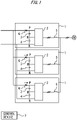
- Fig. 1 is a configuration diagram of a multiple power conversion system according to Embodiment 1.
- the multiple power conversion system includes a plurality of unit power converters 1.
- a DC side is connected to an unillustrated DC power supply.
- an AC side is connected to an AC load.
- Each of the plurality of unit power converters 1 includes a switching element group 2, a positive-side DC capacitor 3, a negative-side DC capacitor 4, and a plurality of reactors 5.
- the switching element group 2 includes a plurality of unillustrated switching elements.
- the positive-side DC capacitor 3 is connected between a DC positive side P and a DC neutral point M in each of the unit power converters 1.
- the negative-side DC capacitor 4 is connected between a DC negative side N and the DC neutral point M in each of the unit power converters 1.
- Fig. 1 only one of the plurality of reactors 5 is illustrated. Each of the plurality of reactors 5 is connected in series to each phase on the AC side.
- the DC positive sides P are connected to one another.
- the DC negative sides N are connected to one another.
- the DC neutral points M are not connected to one another.
- a plurality of DC side current sensors 6 are provided on the respective DC positive sides P of the plurality of unit power converters 1.
- Each of the plurality of DC side current sensors 6 is provided to detect a current flowing through the DC positive side P of the corresponding one of the plurality of unit power converters 1.
- the plurality of DC side current sensors 6 are provided on the respective DC negative sides N of the plurality of unit power converters 1 in some cases. In this case, each of the plurality of DC side current sensors 6 is provided to detect a current flowing through the DC negative side N of the corresponding one of the plurality of unit power converters 1.
- a control device 7 transmits the same gate signal to each of the plurality of unit power converters 1.
- the control device 7 transmits, to each of the plurality of unit power converters 1, a gate signal generated from the same voltage instruction value and different carrier waves.
- the control device 7 calculates a nonuniform amount of the current flowing through each of the plurality of unit power converters 1 based on detection results of the plurality of DC side current sensors 6.
- the control device 7 controls operation of the switching element groups 22 of the plurality of unit power converters 1 based on calculation results of the current nonuniform amounts.
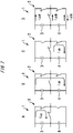
- Fig. 2 is a configuration diagram of the first example of one unit power converter in the multiple power conversion system according to Embodiment 1.
- Fig. 2 illustrates a configuration example of the three-phase three-level unit power converter 1 using self-excited semiconductor devices and diodes.
- the positive-side DC capacitor 3 and the negative-side DC capacitor 4 are connected in series between DC terminals, and the DC neutral point is present at an intermediate point.
- an on signal or an off signal is applied to a gate of each of the self-excited semiconductor devices inside the unit power converter 1
- the potential at any of the DC positive side P, the DC neutral point M, and the DC negative side N is output to an AC terminal of each phase based on the signals.
- Fig. 3 is a configuration diagram of the second example of one unit power converter in the multiple power conversion system according to Embodiment 1.
- Fig. 3 illustrates a configuration example of the three-phase three-level unit power converter 1 using self-excited semiconductor devices and diodes. Also in the unit power converter 1, as with the unit power converter 1 illustrated in Fig. 2 , when an on signal or an off signal is applied to a gate of each of the self-excited semiconductor devices inside the unit power converter 1, the potential at any of the DC positive side P, the DC neutral point M, and the DC negative side N is output to the AC terminal of each phase based on the signals.
- two configurations of the three-phase three-level unit power converter 1 are illustrated; however, the configuration of the unit power converter 1 is not limited to these two configurations.
- the example of the three-phase unit power converter 1 is illustrated; however, the number of phases may be optional number without limitation to the three phase.
- the example of the three-level unit power converter 1 is illustrated; however, the number of levels of the unit power converter 1 is not limited to three, and may be an optional number of three or more.
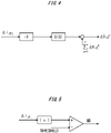
- Fig. 4 is a block diagram to explain the method of suppressing the circulating current in the multiple power conversion system according to Embodiment 1.
- G(s) represents a low-pass filter and a feedback gain.
- a zero-phase voltage (nonuniform amount ⁇ v io ) is output to the AC side of the unit power converter 1 in a direction of suppressing a zero-phase circulating current (nonuniform amount ⁇ i io ).
- the control device 7 calculates a target value ⁇ v io ⁇ of the nonuniform amount of the zero-phase voltage for each of the plurality of unit power converters 1.
- the control device 7 detects a current nonuniform amount ⁇ i iPj of the current and operates the voltage v io , thereby controlling the current nonuniform amount ⁇ i io .
- Fig. 5 is a block diagram to explain the method of protecting the unit power converters 1 in the multiple power conversion system according to Embodiment 1.
- the control device 7 calculates the nonuniform amount ⁇ i iPj of the current flowing through each of the unit power converters 1, and determines whether the calculated value is greater than a preset threshold. In a case where the nonuniform amount ⁇ i iPj of the current flowing through each of the unit power converters 1 is greater than the preset threshold, the control device 7 performs protective operation. More specifically, the control device 7 transmits a gate block signal GB to turn off the plurality of switching element groups 2.
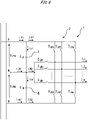
- Fig. 6 is a configuration diagram of a main part of one unit power converter in the multiple power conversion system according to Embodiment 1.
- Fig. 7 is a diagram illustrating short-circuit failure modes of the unit power converter in the multiple power conversion system according to Embodiment 1.
- the control device 7 detects the short-circuit failure based on the detected value of the DC side current sensor 6.
- Fig. 7 illustrates a path through which the current flows when the short-circuit failure occurs. There are modes A to D depending on a position of the short-circuit failure.
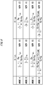
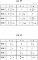
- Fig. 8 and Fig. 9 are diagrams illustrating theoretical values of the nonuniform amount when the short circuit occurs in the multiple power conversion system according to Embodiment 1.
- a physical amount with a subscript i is a physical amount in the unit power converter in which the short-circuit failure has occurred
- a physical amount with a subscript j is a physical amount in the unit power converter other than the unit power converter in which the short-circuit failure has occurred.
- the current nonuniform amount on the DC positive side P is ⁇ i iP1
- the current nonuniform amount on the DC negative side N is ⁇ i iN1 .
- the current nonuniform amount on the DC positive side P is ⁇ i iP1
- the current nonuniform amount on the DC negative side N is ⁇ i jN1 .
- the theoretical value of the nonuniform amount in a unit power converter i in which the short-circuit failure has occurred is represented by a new expression (1) or a new expression (2).
- the new expression (1) represents the nonuniform amount of the detected value in a case where the DC side current sensor 6 is provided on the DC positive side P
- the new expression (2) represents the nonuniform amount of the detected value in a case where the DC side current sensor 6 is provided on the DC negative side N.
- the theoretical value of the nonuniform amount in the unit power converter i in which the short-circuit failure has occurred is represented by a new expression (3) or a new expression (4).
- the new expression (3) represents the nonuniform amount of the detected value in the case where the DC side current sensor 6 is provided on the DC positive side P
- the new expression (4) represents the nonuniform amount of the detected value in the case where the DC side current sensor 6 is provided on the DC negative side N.
- the theoretical value of the nonuniform amount in the unit power converter i in which the short-circuit failure has occurred is represented by a new expression (5) or a new expression (6).
- the new expression (5) represents the nonuniform amount of the detected value in the case where the DC side current sensor 6 is provided on the DC positive side P
- the new expression (6) represents the nonuniform amount of the detected value in the case where the DC side current sensor 6 is provided on the DC negative side N.
- the theoretical value of the nonuniform amount in the unit power converter i in which the short-circuit failure has occurred is represented by a new expression (7) or a new expression (8).
- the new expression (7) represents the nonuniform amount of the detected value in the case where the DC side current sensor 6 is provided on the DC positive side P
- the new expression (8) represents the nonuniform amount of the detected value in the case where the DC side current sensor 6 is provided on the DC negative side N.
- a value smaller than the nonuniform amounts in the new expressions (1) to (8) is set as the threshold to be compared with the nonuniform amount, which makes it possible to detect the short-circuit failure of the unit power converter.
- the nonuniform amount of the unit power converter (with subscript i) in which the short-circuit failure has occurred becomes greater than the nonuniform amount of each of the other unit power converters (with subscript j). Therefore, the nonuniform amounts of the respective unit power converters detected by the control device are compared, and the unit power converter having the greatest nonuniform amount can be specified as the unit power converter in which the failure has occurred. This is because (1 - 1/n) > 1/n is established.
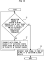
- Fig. 10 is a flowchart to explain the outline of the operation by the control device in the multiple power conversion system according to Embodiment 1.
- step S1 the control device 7 calculates the nonuniform amount of the current flowing through each of the unit power converters 1, and determines whether the calculated value is greater than the preset threshold.
- step S1 the control device 7 performs operation in step S2.
- step S2 the control device 7 transmits the gate signal to the plurality of switching element groups 22 based on the voltage instruction value. Thereafter, the control device 7 performs the operation in step S1.
- step S1 the control device 7 performs operation in step S3.
- step S3 the control device 7 transmits the gate signal to turn off the plurality of switching element groups 2. Thereafter, the control device 7 ends the operation.
- the circulating current is detected based on the detection results of the DC side current sensors 6. Therefore, the circulating current can be detected with a small number of current sensors.
- the circulating current may be detected based on the detection results of the DC side current sensors 6 in the number smaller by one than the number of unit power converters 1. In this case, the circulating current can be detected with a smaller number of current sensors.
- the plurality of unit power converters 1 are controlled based on the detection results of the DC side current sensors 6. Therefore, the circulating current can be suppressed with a small number of current sensors.
- control device 7 transmits the gate signal of the plurality of unit power converters 1 based on the detection results of the plurality of DC side current sensors 6, thereby suppressing a zero-phase component of the circulating current.
- a margin to a rated current of a component (mainly, AC reactor) rating considering superimposition can be made small, which makes it possible to suppress an excess cost.
- control device 7 turns off at least one switching element of the plurality of unit power converters 1 based on the detection results of the plurality of DC side current sensors 6. Accordingly, when the short-circuit failure, abnormal reduction in a capacity, or abnormal increase in a leakage current of the positive-side DC capacitor 3 or the negative-side DC capacitor 4 is detected, it is possible to prevent overheat, rupture, and liquid leakage of the positive-side DC capacitor 3 or the negative-side DC capacitor 4.
- occurrence of abnormality for example, the short-circuit failure, the capacity reduction, and the increase in a leakage current of the positive-side DC capacitor or the negative-side DC capacitor, and abnormal reduction of inductance caused by interlayer short-circuit failure of the AC reactor is also detectable without limitation to the short-circuit failure of the switching element. This is because, in a case where such abnormality occurs, the nonuniform amount of the detected value of each of the DC side current sensors 6 has a certain magnitude, and abnormality can be determined when the detection threshold is set lower than the magnitude.
- the abnormality may be determined by a method similar to the method disclosed in JP 2017-22816 A .
- a switch may be provided on at least one of the DC positive side and the DC negative side. At this time, based on the detected values of the plurality of current sensors, the switch may be turned off in the unit power converter 1 in failure, and operation may be performed only by the sound unit power converters 1.
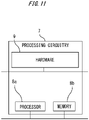
- control device 7 Next, an example of the control device 7 is described with reference to Fig. 11 .
- Fig. 11 is a hardware configuration diagram of the control device in the multiple power conversion system according to Embodiment 1.
- control device 7 can be realized by a processing circuitry.
- the processing circuitry includes at least one processor 8a and at least one memory 8b.
- the processing circuitry includes at least one dedicated hardware 9.
- each of the functions of the control device 7 is realized by software, firmware, or a combination of the software and the firmware.
- At least one of the software and the firmware is described as a program.
- At least one of the software and the firmware is stored in the at least one memory 8b.
- the at least one processor 8a reads out and executes a program stored in the at least one memory 8b, to realize each of the functions of the control device 7.
- the at least one processor 8a is also referred to as a central processing unit, a processing device, a calculation device, a microprocessor, a microcomputer, or a DSP.
- the at least one memory 8b is a nonvolatile or volatile semiconductor memory such as a RAM, a ROM, a flash memory, an EPROM, and an EEPROM, a magnetic disk, a flexible disk, an optical disk, a compact disk, a minidisk, or a DVD.
- a nonvolatile or volatile semiconductor memory such as a RAM, a ROM, a flash memory, an EPROM, and an EEPROM, a magnetic disk, a flexible disk, an optical disk, a compact disk, a minidisk, or a DVD.
- the processing circuitry includes the at least one dedicated hardware 9
- the processing circuitry is realized by, for example, a single circuit, a composite circuit, a programmed processor, a parallel-programmed processor, an ASIC, a FPGA, or a combination thereof.
- the functions of the control device 7 are each realized by the processing circuitry.
- the functions of the control device 7 are collectively realized by the processing circuitry.
- a part of the functions of the control device 7 may be realized by the dedicated hardware 9, and the other functions may be realized by the software or the firmware.
- the function of transmitting the gate signal may be realized by the processing circuitry serving as the dedicated hardware 9, and the functions other than the function of transmitting the gate signal may be realized in such a manner that the at least one processor 8a reads out and executes programs stored in the at least one memory 8b.
- the processing circuitry realizes the functions of the control device 7 by the hardware 9, the software, the firmware, or a combination thereof.
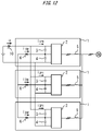
- Fig. 12 is a configuration diagram of a multiple power conversion system according to Embodiment 2. Note that the parts same as or equivalent to the parts according to Embodiment 1 are denoted by the same reference numerals. Descriptions of the parts are omitted.
- the DC neutral points M are not connected to one another. In contrast, in the plurality of unit power converters 1 according to Embodiment 2, the DC neutral points M are connected to one another.
- the plurality of DC side current sensors 6 are provided at the respective DC neutral points M of the plurality of unit power converters 1.
- Each of the plurality of DC side current sensors 6 is provided to detect a current flowing through the DC neutral point M of the corresponding one of the plurality of unit power converters 1.
- the plurality of DC side current sensors 6 are provided at the respective DC neutral points M of the unit power converters 1 except for one of the plurality of unit power converters 1 in some cases.
- each of the plurality of DC side current sensors 6 is provided to detect the current flowing through the DC neutral point of the corresponding one of the unit power converters 1 except for one of the plurality of unit power converters 1.
- a DC side integration current sensor 10 is provided on the DC positive side P.
- the DC side integration current sensor 10 is provided to detect the current flowing through the DC positive side P.
- the control device 7 calculates the nonuniform amount of the current flowing through each of the plurality of unit power converters 1 based on the detection results of the plurality of DC side current sensors 6.
- the control device 7 controls operation of the switching element groups 2 of the plurality of unit power converters 1 based on the calculation results of the current nonuniform amounts.
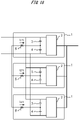
- Fig. 13 is a configuration diagram of a main part of one unit power converter in the multiple power conversion system according to Embodiment 2.
- control device 7 detects the short-circuit failure based on the detected values of the DC side current sensor 6 and the DC side integration current sensor 10.
- Fig. 14 and Fig. 15 are diagrams illustrating theoretical values of the nonuniform amount when the short circuit occurs in the multiple power conversion system according to Embodiment 2.
- a physical amount with a subscript i is a physical amount in the unit power converter in which the short-circuit failure has occurred
- a physical amount with a subscript j is a physical amount in the unit power converter other than the unit power converter in which the short-circuit failure has occurred.
- the current nonuniform amount on the DC positive side P is ⁇ i ip1
- the current nonuniform amount at the DC neutral point M is ⁇ i iM1
- the current nonuniform amount on the DC negative side N is ⁇ i iN1 .
- the current nonuniform amount on the DC positive side P is ⁇ i iP1
- the current nonuniform amount at the DC neutral point M is ⁇ i jM1
- the current nonuniform amount on the DC negative side N is ⁇ i jN1 .
- a value smaller than the nonuniform amounts ⁇ i ip1 , ⁇ i iN1 , and ⁇ i iM1 is set as the threshold to be compared with the nonuniform amount, which makes it possible to detect the short-circuit failure of the unit power converter.
- the nonuniform amount of the unit power converter (with subscript i) in which the short-circuit failure has occurred becomes greater than the nonuniform amount of each of the other unit power converters (with subscript j). Therefore, the nonuniform amounts of the respective unit power converters detected by the control device are compared, and the unit power converter having the greatest nonuniform amount can be specified as the unit power converter in which the failure has occurred. This is because (1 - 1/n) > 1/n is established.
- the circulating current is detected based on the detection results of the DC side current sensors 6 and the DC side integration current sensor 10. Therefore, the circulating current can be detected with a small number of current sensors.
- the plurality of unit power converters 1 are controlled based on the detection results of the DC side current sensors 6 and the DC side integration current sensor 10. Therefore, the circulating current can be suppressed with a small number of current sensors.
- each of the DC side current sensors 6 detects the current flowing through the corresponding DC neutral point M.
- the current is smaller than the current flowing through the DC positive side P and the current flowing through the DC negative side N. Accordingly, it is possible to reduce the rating of each of the DC side current sensors 6.
- a conductor may be thin. This facilitates arrangement of the DC side current sensors 6. As a result, it is possible to enhance flexibility of mounting of the DC side current sensors 6.
- the short-circuit failure can be detected by calculating the nonuniform amounts ⁇ i ip1 and ⁇ i iN1 on the positive sides P and the negative sides N, and comparing the nonuniform amounts ⁇ i ip1 and ⁇ i iN1 with the threshold.
- Fig. 16 is a configuration diagram of a multiple power conversion system according to Embodiment 3. Note that the parts same as or equivalent to the parts according to Embodiment 2 are denoted by the same reference numerals. Descriptions of the parts are omitted.
- the plurality of DC side current sensors 6 are provided on the respective unit power converters 1. Each of the plurality of DC side current sensors 6 is provided to detect a difference between the current flowing through the DC positive side P and the current flowing through the DC negative side N of the corresponding one of the plurality of unit power converters 1 at once.
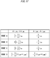
- Fig. 17 is a diagram illustrating the theoretical values of the nonuniform amount when the short circuit occurs in the multiple power conversion system according to Embodiment 3.
- a physical amount with a subscript i is a physical amount in the unit power converter in which the short-circuit failure has occurred
- a physical amount with a subscript j is a physical amount in the unit power converter other than the unit power converter in which the short-circuit failure has occurred.
- the current nonuniform amount on the DC positive side P is ⁇ i ip1
- the current nonuniform amount on the DC negative side N is ⁇ i iN1 .
- the current nonuniform amount on the DC positive side P is ⁇ i iP1
- the current nonuniform amount on the DC negative side N is ⁇ i jN1 .
- a value smaller than the nonuniform amount ⁇ i iP1 or ⁇ i iN1 shown in Fig. 17 is set as the threshold to be compared with the nonuniform amount, which makes it possible to detect the short-circuit failure of the unit power converter.
- the nonuniform amount of the unit power converter (with subscript i) in which the short-circuit failure has occurred becomes greater than the nonuniform amount of each of the other unit power converters (with subscript j). Therefore, the nonuniform amounts of the respective unit power converters detected by the control device are compared, and the unit power converter having the greatest nonuniform amount can be specified as the unit power converter in which the failure has occurred. This is because (1 - 1/n) > 1/n is established.
- each of the plurality of DC side current sensors 6 detects differences between the currents flowing through the DC positive side P and the DC negative side N of the plurality of unit power converters 1 at once. Therefore, the circulating current can be detected with a small number of current sensors.
- control device can detect the short-circuit failure of all of the mode A to the mode D based on the detection results of the plurality of DC side current sensors 6.
- Fig. 18 is a configuration diagram of a multiple power conversion system according to Embodiment 4. Note that the parts same as or equivalent to the parts according to Embodiment 2 are denoted by the same reference numerals. Descriptions of the parts are omitted.
- Each of the unit power converters 1 according to Embodiment 4 is a two-level power converter.
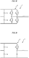
- Fig. 19 is a configuration diagram of the first example of one unit power converter in the multiple power conversion system according to Embodiment 4.
- Fig. 19 illustrates a configuration example of the two-level unit power converter 1 that converts DC power into AC power.
- Fig. 20 is a configuration diagram of the second example of one unit power converter in the multiple power conversion system according to Embodiment 4.
- Fig. 20 illustrates a configuration example of the two-level power converter 1 that converts DC power into DC power.
- the DC side current sensors 6 are provided in the respective two-level unit power converters 1. Even in this case, the circulating current can be detected with a small number of current sensors.
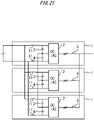
- Fig. 21 is a configuration diagram of a multiple power conversion system according to Embodiment 5. Note that the parts same as or equivalent to the parts according to Embodiment 2 are denoted by the same reference numerals. Descriptions of the parts are omitted.
- Embodiment 5 a plurality of reactors 11 are provided on the DC positive sides P and the DC negative sides N of the plurality of unit power converters 1.
- the plurality of reactors 11 are provided on the DC positive sides P of the plurality of unit power converters 1. Also, in this case, the circulating current can be detected with a small number of current sensors.
- the reactors 11 may be provided on the respective DC neutral points M. Also, in this case, the circulating current can be detected with a small number of current sensors.
- Fig. 22 is a configuration diagram of a multiple power conversion system according to Embodiment 6. Note that the parts same as or equivalent to the parts according to Embodiment 2 are denoted by the same reference numerals. Descriptions of the parts are omitted.
- an output side of each of the plurality of unit power converters 1 is connected to a single-phase multiple winding transformer.
- Each of the plurality of unit power converters 1 is a unit power converter 1 for one phase.
- An AC side current sensor 12 is provided on the output side of any one of the plurality of unit power converters 1.
- Fig. 23 is a configuration diagram of a multiple power conversion system according to Embodiment 7. Note that the parts same as or equivalent to the parts according to Embodiment 6 are denoted by the same reference numerals. Descriptions of the parts are omitted.
- each of the plurality of unit power converters 1 is connected to a three-phase multiple winding transformer.
- Each of a plurality of AC side current sensors 12 is provided on the output side of the unit power converter 1 corresponding to two phases of the plurality of unit power converters 1.
- each of the plurality of AC side current sensors 12 is provided on the output side of the unit power converter 1 corresponding to the two phases of the plurality of unit power converters 1. Also, in this case, the circulating current can be suppressed, and the number of current sensors can be reduced.
- the current sensors on the AC side are provided at, for example, points U1, U2, U3, V1, V2, and V3 in order to detect and suppress the circulating current among the points U1, U2, and U3, the circulating current among the points V1, V2, and V3, and the circulating current among points W1, W2, and W3 or in order to detect failure.
- the current sensors for the W phase are unnecessary because the current in the W phase can be calculated from Kirchhoff s current law.
- the current sensors 6 are provided at the respective neutral points of the unit power converters as with the present embodiment, the circulating current can be suppressed by these sensors, or the failure can be detected as with Embodiment 2.
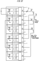
- Fig. 24 is a configuration diagram of a multiple power conversion system according to Embodiment 8. Note that the parts same as or equivalent to the parts according to Embodiment 6 are denoted by the same reference numerals. Descriptions of the parts are omitted.
- a plurality of reactors 13 are provided on the respective output sides of the plurality of unit power converters 1.
- the plurality of reactors 13 are provided on the respective output sides of the plurality of unit power converters 1. Also, in this case, the circulating current can be suppressed, and the number of current sensors can be reduced.
- the current sensors on the AC side are provided at, for example, points U1, U2, and U3 in order to detect and suppress the circulating current among the points U1, U2, and U3 or in order to detect failure.
- the current sensors for the V phase are unnecessary because the current in the V phase can be calculated from Kirchhoff s current law.
- the current sensors 6 are provided on the respective neutral points of the unit power converters as with the present embodiment, the circulating current can be suppressed by these sensors, or the failure can be detected as with Embodiment 2. Accordingly, it is unnecessary to use the current values at all of the points U1, U2, and U3.
- the reason of remaining the current sensor at the point U1 is to recognize a total value of the currents on the AC side.
- the current values at the points U1, U2, and U3 are equivalent to one another, and the current values at the points V1, V2, and V3 are equivalent to one another.
- Using the fact and Kirchhoff s current law allows for estimation of the current values at all of the points U1, U2, U3, V1, V2, and V3. As a result, a total value of the currents on the AC side can be estimated.
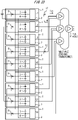
- Fig. 25 is a configuration diagram of a multiple power conversion system according to Embodiment 9. Note that the parts same as or equivalent to the parts according to Embodiment 6 are denoted by the same reference numerals. Descriptions of the parts are omitted.
- the plurality of unit power converters 1 are divided into sets corresponding to different phases.
- the DC neutral points M are connected to one another.
- the DC neutral points M are not connected to one another.
- the plurality of DC side current sensors 6 are provided on the respective DC positive sides P of the plurality of unit power converters 1.
- Each of the plurality of DC side current sensors 6 is provided to detect a current flowing through the DC positive side P of the corresponding one of the plurality of unit power converters 1.
- the plurality of DC side current sensors 6 are provided on the respective DC negative sides N of the plurality of unit power converters 1 in some cases. In this case, each of the plurality of DC side current sensors 6 is provided to detect a current flowing through the DC negative side N of the corresponding one of the plurality of unit power converters 1.
- the DC neutral points M are connected to one another.
- the DC neutral points M are not connected to one another.
- the current sensors on the AC side are provided at, for example, points U1, U2, and U3 in order to detect and suppress the circulating current among the points U1, U2, and U3 and the circulating current among the points V1, V2, and V3 or in order to detect failure.
- the current sensors for the V phase are unnecessary because the current in the V phase can be calculated from Kirchhoff s current law.
- the current sensors 6 are provided on the respective DC sides of the unit power converters, the circulating current can be suppressed by these sensors, or the failure can be detected as with Embodiment 2. Accordingly, it is unnecessary to use the current values at all of the points U1, U2, and U3.
- the reason of remaining the current sensor at the point U1 is to recognize a total value of the currents on the AC side.
- the current values at the points U1, U2, and U3 are equivalent to one another, and the current values at the points V1, V2, and V3 are equivalent to one another.
- Using the fact and Kirchhoff s current law allows for estimation of the current values at all of the points U1, U2, U3, V1, V2, and V3. As a result, a total value of the currents on the AC side can be estimated.
- the failure can be detected at high speed as compared with the case where the current sensors are provided at the points U1, U2, and U3 on the AC side. This is because change of the current when the failure occurs is steeper on the DC side than on the AC side.
- a plurality of switches may be provided on at least two of the DC positive side P, the DC negative side N, and the DC neutral point M.
- the plurality of switches in the unit power converters 1 in failure are turned off based on the detected values of the plurality of DC side current sensors 6.
- the multiple power conversion system according to the present invention is usable in a system that detects the circulating current with a small number of current sensors.
Landscapes
- Engineering & Computer Science (AREA)
- Power Engineering (AREA)
- Inverter Devices (AREA)
Applications Claiming Priority (1)
| Application Number | Priority Date | Filing Date | Title |
|---|---|---|---|
| PCT/JP2019/028871 WO2021014574A1 (fr) | 2019-07-23 | 2019-07-23 | Système de conversion de puissance multiplex |
Publications (2)
| Publication Number | Publication Date |
|---|---|
| EP4007154A1 true EP4007154A1 (fr) | 2022-06-01 |
| EP4007154A4 EP4007154A4 (fr) | 2023-02-08 |
Family
ID=74193545
Family Applications (1)
| Application Number | Title | Priority Date | Filing Date |
|---|---|---|---|
| EP19938114.6A Pending EP4007154A4 (fr) | 2019-07-23 | 2019-07-23 | Système de conversion de puissance multiplex |
Country Status (5)
| Country | Link |
|---|---|
| US (1) | US20220085733A1 (fr) |
| EP (1) | EP4007154A4 (fr) |
| JP (1) | JP7294424B2 (fr) |
| CN (1) | CN113228493B (fr) |
| WO (1) | WO2021014574A1 (fr) |
Families Citing this family (1)
| Publication number | Priority date | Publication date | Assignee | Title |
|---|---|---|---|---|
| WO2021038698A1 (fr) * | 2019-08-26 | 2021-03-04 | 株式会社デンソー | Onduleur |
Family Cites Families (18)
| Publication number | Priority date | Publication date | Assignee | Title |
|---|---|---|---|---|
| JPH01122370A (ja) * | 1987-11-05 | 1989-05-15 | Mitsubishi Electric Corp | トランジスタインバータ装置 |
| JP3180961B2 (ja) * | 1991-04-19 | 2001-07-03 | 東芝エフエーシステムエンジニアリング株式会社 | ブリッジ形変換器の保護装置 |
| JPH06319263A (ja) * | 1991-07-26 | 1994-11-15 | Hitachi Ltd | インバータ装置 |
| US5790396A (en) * | 1995-12-19 | 1998-08-04 | Kabushiki Kaisha Toshiba | Neutral point clamped (NPC) inverter control system |
| JP3968572B2 (ja) * | 2002-06-07 | 2007-08-29 | サンケン電気株式会社 | 複数台のインバータを並列接続した電力変換装置 |
| JP2005185003A (ja) * | 2003-12-19 | 2005-07-07 | Yaskawa Electric Corp | 電力変換装置の保護装置 |
| JP4322173B2 (ja) | 2004-06-17 | 2009-08-26 | 富士通株式会社 | データ転送方法及びシステム、入出力要求装置、並びに、データ転送プログラム及び同プログラムを記録したコンピュータ読取可能な記録媒体 |
| CN101953062B (zh) * | 2009-02-20 | 2013-07-10 | 东芝三菱电机产业系统株式会社 | 电力转换装置 |
| JP5739734B2 (ja) * | 2011-06-08 | 2015-06-24 | 東芝三菱電機産業システム株式会社 | 電力変換装置 |
| JP2014236530A (ja) * | 2013-05-30 | 2014-12-15 | 富士電機株式会社 | 電力変換装置 |
| JP6289675B2 (ja) * | 2014-12-24 | 2018-03-07 | 三菱電機株式会社 | 電力変換装置 |
| US9450479B2 (en) * | 2015-02-20 | 2016-09-20 | Ge Energy Power Conversion Technology Ltd | Systems and methods to optimize active current sharing of parallel power converters |
| CN107820670A (zh) * | 2015-07-03 | 2018-03-20 | 东芝三菱电机产业系统株式会社 | 电力转换装置的控制装置 |
| JP6348460B2 (ja) | 2015-07-08 | 2018-06-27 | 東芝三菱電機産業システム株式会社 | 電力変換システム |
| DE102015114452B4 (de) * | 2015-08-31 | 2017-05-04 | Sma Solar Technology Ag | Verfahren zum Betrieb eines Wechselrichters und Wechselrichter |
| JP6319263B2 (ja) | 2015-10-16 | 2018-05-09 | 京セラドキュメントソリューションズ株式会社 | 画像形成システム、ジョブ制御装置、ジョブ制御方法、及びコンピュータープログラム |
| JP6817881B2 (ja) * | 2017-04-21 | 2021-01-20 | 株式会社日立製作所 | 電力変換装置、及び異常検出方法 |
| US10644612B2 (en) * | 2017-11-30 | 2020-05-05 | General Electric Company | System of input current sharing for compact architecture in a power converter |
-
2019
- 2019-07-23 CN CN201980085810.2A patent/CN113228493B/zh active Active
- 2019-07-23 EP EP19938114.6A patent/EP4007154A4/fr active Pending
- 2019-07-23 JP JP2021534459A patent/JP7294424B2/ja active Active
- 2019-07-23 US US17/416,623 patent/US20220085733A1/en active Pending
- 2019-07-23 WO PCT/JP2019/028871 patent/WO2021014574A1/fr unknown
Also Published As
| Publication number | Publication date |
|---|---|
| CN113228493B (zh) | 2023-11-28 |
| JPWO2021014574A1 (fr) | 2021-01-28 |
| WO2021014574A1 (fr) | 2021-01-28 |
| US20220085733A1 (en) | 2022-03-17 |
| EP4007154A4 (fr) | 2023-02-08 |
| CN113228493A (zh) | 2021-08-06 |
| JP7294424B2 (ja) | 2023-06-20 |
Similar Documents
| Publication | Publication Date | Title |
|---|---|---|
| CN108702089B (zh) | 转换器装置 | |
| AU2005290575B2 (en) | Power supply circuit protecting method and apparatus for the same | |
| EP3905507A1 (fr) | Dispositif de conversion de puissance | |
| US11909307B2 (en) | Power conversion device | |
| EP1411624B1 (fr) | Onduleur | |
| EP4120544A1 (fr) | Dispositif de conversion de puissance | |
| JP2017085771A (ja) | 多相コンバータ | |
| EP4120545A1 (fr) | Dispositif de conversion de puissance | |
| EP4007154A1 (fr) | Système de conversion de puissance multiplex | |
| EP3905508A1 (fr) | Dispositif de conversion de puissance | |
| EP3258563B1 (fr) | Dispositif de protection et système de protection | |
| US12046991B2 (en) | Multiplex power conversion system having means to prevent failure spread | |
| JP6365012B2 (ja) | 分散型電源システム | |
| US20230098992A1 (en) | Power conversion system | |
| CN107852098B (zh) | 功率转换装置 | |
| WO2020030245A1 (fr) | Procédé de commande d'un mmc | |
| JPH11332246A (ja) | 過電流検出装置 |
Legal Events
| Date | Code | Title | Description |
|---|---|---|---|
| STAA | Information on the status of an ep patent application or granted ep patent |
Free format text: STATUS: THE INTERNATIONAL PUBLICATION HAS BEEN MADE |
|
| PUAI | Public reference made under article 153(3) epc to a published international application that has entered the european phase |
Free format text: ORIGINAL CODE: 0009012 |
|
| STAA | Information on the status of an ep patent application or granted ep patent |
Free format text: STATUS: REQUEST FOR EXAMINATION WAS MADE |
|
| 17P | Request for examination filed |
Effective date: 20210629 |
|
| AK | Designated contracting states |
Kind code of ref document: A1 Designated state(s): AL AT BE BG CH CY CZ DE DK EE ES FI FR GB GR HR HU IE IS IT LI LT LU LV MC MK MT NL NO PL PT RO RS SE SI SK SM TR |
|
| DAV | Request for validation of the european patent (deleted) | ||
| DAX | Request for extension of the european patent (deleted) | ||
| A4 | Supplementary search report drawn up and despatched |
Effective date: 20230109 |
|
| RIC1 | Information provided on ipc code assigned before grant |
Ipc: H02M 1/00 19680901ALN20230102BHEP Ipc: H02M 7/5387 19850101ALI20230102BHEP Ipc: H02M 1/32 20070101ALI20230102BHEP Ipc: H02M 7/487 20070101ALI20230102BHEP Ipc: H02M 7/493 20070101AFI20230102BHEP |
|
| STAA | Information on the status of an ep patent application or granted ep patent |
Free format text: STATUS: EXAMINATION IS IN PROGRESS |
|
| 17Q | First examination report despatched |
Effective date: 20240122 |