EP4006536A1 - Elektrophoresegerät und methoden - Google Patents
Elektrophoresegerät und methoden Download PDFInfo
- Publication number
- EP4006536A1 EP4006536A1 EP20210257.0A EP20210257A EP4006536A1 EP 4006536 A1 EP4006536 A1 EP 4006536A1 EP 20210257 A EP20210257 A EP 20210257A EP 4006536 A1 EP4006536 A1 EP 4006536A1
- Authority
- EP
- European Patent Office
- Prior art keywords
- molecules
- frames
- interest
- separation matrix
- electrodes
- Prior art date
- Legal status (The legal status is an assumption and is not a legal conclusion. Google has not performed a legal analysis and makes no representation as to the accuracy of the status listed.)
- Withdrawn
Links
Images


Classifications
-
- G—PHYSICS
- G01—MEASURING; TESTING
- G01N—INVESTIGATING OR ANALYSING MATERIALS BY DETERMINING THEIR CHEMICAL OR PHYSICAL PROPERTIES
- G01N27/00—Investigating or analysing materials by the use of electric, electrochemical, or magnetic means
- G01N27/26—Investigating or analysing materials by the use of electric, electrochemical, or magnetic means by investigating electrochemical variables; by using electrolysis or electrophoresis
- G01N27/416—Systems
- G01N27/447—Systems using electrophoresis
- G01N27/44704—Details; Accessories
- G01N27/44717—Arrangements for investigating the separated zones, e.g. localising zones
- G01N27/44739—Collecting the separated zones, e.g. blotting to a membrane or punching of gel spots
-
- G—PHYSICS
- G01—MEASURING; TESTING
- G01N—INVESTIGATING OR ANALYSING MATERIALS BY DETERMINING THEIR CHEMICAL OR PHYSICAL PROPERTIES
- G01N27/00—Investigating or analysing materials by the use of electric, electrochemical, or magnetic means
- G01N27/26—Investigating or analysing materials by the use of electric, electrochemical, or magnetic means by investigating electrochemical variables; by using electrolysis or electrophoresis
- G01N27/416—Systems
- G01N27/447—Systems using electrophoresis
- G01N27/44756—Apparatus specially adapted therefor
- G01N27/44782—Apparatus specially adapted therefor of a plurality of samples
Definitions
- Gel separating matrices are typically made by pouring a liquid phase into a mold and letting the matrices solidify. In slab gel electrophoresis, outcroppings in plastic material form combs embedded in the top of the separating matrix. These allow the formation of sample loading wells when the combs are removed after solidification of the matrix. In order to separate the molecules, the gel matrix is placed in appropriate electrophoresis buffers, and an electrical field is generated.
- Blotting is a process used to transfer molecules from an electrophoresis matrix to a membrane for further analysis, such as Southern, Northern, Western or Eastern blotting.
- the separation matrix containing the electrophoresed biological material is removed from the electrophoresis apparatus and placed in a blotting sandwich.
- the blotting sandwich generally consists of buffer saturated sponges and paper pads; a gel containing the separated biologicals; a suitable transfer membrane that is in intimate contact with the separating matrix; and another layer of buffer saturated paper pads and sponges.
- electrotransfer electrodes and buffer may provide an electrical field to move the molecules out of the separating matrix and into the membrane.
- electrophoresis assembly disclosed herein in a method for performing electrophoresis or in a method for performing electroblotting as disclosed herein.
- the present electrophoresis assemblies are particularly useful for performing high-throughput electrophoresis in a convenient, time-saving and labour-saving manner. They can be used to perform electrophoresis in a bufferless environment, where the only required buffer is supplied within each respective inner frame.
- the electrophoresis assemblies of the present disclosure comprise at least two frames (2), each of which is configured for holding at least one inner frame (3) which is configured for holding at least one separation matrix (4) such as a gel or a liquid separation matrix.
- the electrophoresis assembly is dynamic, and can adopt two main configurations.
- the electrophoresis assembly of the present disclosure may be reusable or may be intended for a single use.
- SBS formats or SLAS standards are defined by two dimensions: a first dimension corresponding to rows, and a second dimension corresponding to columns.
- the electrophoresis assembly described herein thus matches a 48-well standard (arranged in 6 X 8), a 96-well standard (arranged in 8 X 12), a 384-well standard (arranged in 16 first openings X 24 frames, or in 16 frames X 24 first openings), a 1536-well standard (arranged in 32 first openings X 48 frames, or in 32 frames X 48 first openings), a 3456-well standard (arranged in 48 X 72) or a 9600-well format (arranged in 120 X 80).
- the assembly when in the second configuration can form a closed perimeter.
- the assembly comprises at least three frames, and the two frames located in the extremities of the assembly can be connected to one another; the assembly can thus form a closed perimeter.
- the closed perimeter thus formed can adopt various shapes.
- An assembly comprising three frames will have an essentially triangular shape.
- An assembly comprising an even number of frames can have an essentially rectangular shape.
- An assembly comprising four frames, or a number of frames which is a multiple of four, can have an essentially square shape.
- An assembly comprising an even number of frames greater than four, in particular an even number which is not a multiple of four can have an essentially regular shape. Uneven numbers of frames will result in other shapes.
- the assembly can however also be used in configurations where the frames when in the second configuration, do not form a closed perimeter.
- the two or more frames may comprise an inner cavity on a lateral surface, or a lateral surface or a lateral side of the two or more frames may comprise a transparent surface, which allows optical access to the inner frame(s), and hence to the separation matrix/matrices, held in the assembly, at least in the second configuration.
- a transparent surface when present is made of a material which allows optical access, in particular transmission of light, such as UV light, laser light or blue light.
- the frame may comprise a sheet, which can be peeled off, cut, removed or pierced, and which can be fixed thereon. The sheet can be peeled off, cut, removed or pierced, either to facilitate extraction of the separated molecules of interest, or prior to performing electroblotting if it is desirable to do so.
- the assembly comprises at least two frames, such as at least three frames, such as at least four frames, such as at least five frames, such as at least six frames, such as at least seven frames, such as at least eight frames, such as at least nine frames, such as at least ten frames, such as at least eleven frames, such as at least twelve frames, or more.
- Each frame may comprise one inner frame or more, such as two inner frames.
- each frame comprises one inner frame.
- each frame comprises two inner frames.
- the assembly comprises two frames and four inner frames, two in each frame, or the assembly comprises three frames and six inner frames, four frames and eight inner frames, five frames and ten inner frames, six frames and twelve inner frames, seven frames and fourteen inner frames, eight frames and sixteen inner frames, nine frames and eighteen inner frames, ten frames and twenty inner frames, eleven frames and twenty-two inner frames, or twelve frames and twenty-four inner frames, or more.
- some frames comprise one inner frame and some frames comprise two inner frames.
- the frame is defined by lateral walls which allow optical access to the inner chamber, i.e. which allow optical access to the separation matrix held in the inner chamber at least when the electrophoresis assembly is in the second configuration.
- the lateral walls of the frame may be hollow, and thus define a frame cavity, or they may be manufactured from a material allowing optical access through one lateral side, thus enabling optical access to the separation matrix held in the inner frame at least when the electrophoresis assembly is in the second configuration.
- the lateral sides of the frame preferably consist of a material which allows transmission of light, such as UV light, laser light or blue light.
- the frames comprise a hinge.
- the frame defines a rectangle comprising four sides: an upper side (where the inner frame can be introduced through the opening (18)), and a lower side, a right side and a left side (which together hold the inner frame with the separation matrix in place).
- the hinge is preferably located on the right side and/or on the left side of the frame.
- the hinge is preferably not located on the upper side or on the lower side.
- the hinge may be one hinge, two hinges, three hinges or more.
- the frame(s) comprise(s) a hinge on one side
- additional connection means on another side for example magnets (30, 30').
- the frame may thus comprise a hinge on at least one side, through which it can be connected to another identical frame, and may further comprise additional connection means such as magnets on another side.
- the additional connection means may be located on the side of the frame opposite to the hinge, and/or they may be located on the upper and/or the lower end of the frame.
- Such additional connection means may help maintain the inner frames comprised in the assembly in place to facilitate introduction of a liquid or a molten separation matrix in the inner chamber (5) of the inner frames (3) and/or to facilitate loading of samples in the assembly, as they may prevent the creation of gaps between the frames.
- the additional connection means are magnets.
- the magnets may be coated with isolating material or cushioning material.
- the inner frame comprises: an inner chamber (5) configured for receiving and holding the separation matrix, a buffer chamber (6) configured for receiving and holding a buffer solution, and a set of electrodes consisting of a set of first electrodes (29) and a set of second electrodes (29').
- the inner frame is thus defined by the inner chamber (5) and the buffer chamber (6) as well as by an upper wall (26) and a lower wall (34).
- the sheet provides a fluid-tight separation and protects the separation matrix, thus avoiding its drying out, for example at least until samples are loaded or until electrophoresis is complete.
- the sheet can be peeled off, cut, removed or pierced prior to extracting the separated molecules of interest or prior to performing electroblotting, if desired.
- the upper wall (27) of the inner chamber (5) comprises a first plurality of openings (10, 10'). These are configured to match an SBS and/or an SLAS format or standard, which enables the use of a liquid handler to perform electrophoresis.
- the first plurality of openings can in practice be in the form of channels or ports, for example defined by a lateral wall which protrudes at least in the upper compartment, and optionally also in the inner chamber.
- the lateral wall in practice helps containing the samples so that these remain in the vicinity of the first openings, such that when an electrical current is applied to the electrophoresis assembly, charged molecules comprised within the samples can migrate electrophoretically into the separation matrix so that electrophoresis can be performed.
- the lateral wall also facilitates loading of the samples.
- the electrophoresis assembly can thus match a 48-well standard (arranged in 6 X 8), a 96-well standard (arranged in 8 X 12), a 384-well standard (arranged in 16 first openings X 24 frames, or in 16 frames X 24 first openings), a 1536-well standard (arranged in 32 first openings X 48 frames, or in 32 frames X 48 first openings), a 3456-well standard (arranged in 48 X 72) or a 9600-well format (arranged in 120 X 80).
- the buffer chamber (6) can consist of a single chamber, as shown for example on Figures 1 and 2 , which may be divided in several compartments, for example an upper compartment (7) located at the upper end of the inner chamber, a lower compartment (8) located at the lower end of the inner chamber, and a lateral compartment (9) which is in fluid communication with both the upper compartment and the lower compartment.
- the buffer chamber may alternatively consist of several compartments which are not in fluid communication with one another, for example a lower compartment and an upper compartment.
- the buffer chamber is preferably filled or at least partially filled with a buffer solution prior to use.
- the buffer chamber is fluid-tight, i.e.
- the buffer chamber is configured to receive a buffer solution, which is a conductive fluid suitable for performing sample migration, e.g. by electrophoresis.
- the inner chamber holding the separation matrix preferably does not comprise the buffer, or is essentially devoid of buffer.
- Separation matrices typically contain a high percentage of conductive fluid, which is sufficient for separating the molecules in the samples without actually submerging the separation matrix in the buffer.
- the buffer may comprise a dye or a marker allowing for staining or visualisation of the samples, such as any of the dyes and stains described herein below.
- a dye or a marker allowing for staining or visualisation of the samples, such as any of the dyes and stains described herein below.
- RedSafe or ethidium bromide may be added to buffers used in electrophoresis migration of nucleic acids, as is known in the art.
- Adding a dye or a stain to the conductive fluid may be desirable in some embodiments, and renders the addition of a dye or a stain to the sample unnecessary.
- the third plurality of openings may thus match the same SBS and/or SLAS format as the first and second pluralities of openings, or it may match a different SBS and/or SLAS format.
- the inner frame comprises a pierceable seal (14) covering the second plurality of openings.
- the pierceable seal is penetrable and fluid-tight, and can be made as is known in the art, for example it is made of aluminium foil or a sealant such as a rubber sealant.
- the inner frame further comprises a pierceable, fluid-tight bottom layer (12) in its lower end.
- the electrophoresis assembly in some embodiments is provided with a first plurality of first piercing elements in the lower part of the frame.
- the bottom layer at least in those embodiments is made of a material that allows the first piercing elements to penetrate the supporting layer, so that they go through the supporting layer.
- the supporting layer can thus be manufactured from rubber or silicone, or any other suitable material known in the art.
- the frames hold more than one inner frame.
- each frame holds two inner frames.
- optical access to the separation matrix held within each inner frame is possible from one lateral side.
- blocking means can consist of a non-transparent barrier (21).
- the barrier may be in the form of a sheet or a membrane. This allows optical access to only one separation matrix from one given lateral side at least when the assembly is in the second configuration.
- the frame can in such cases be flanked by two detection means, which independently each monitor a single separation matrix in one of the two inner frames; these can be monitored simultaneously.
- Such blocking means may be external to the inner frames, for example they may comprise or consist of a non-transparent sheet separating the two inner frames from one another, or they may be integrated in one inner frame, thus dividing the inner frame in two.
- the blocking means comprise or consist of a coating on the back part of the containers, wherein said coating is configured to prevent optical access to one of the two separation matrices, at least when the assembly is in the second configuration.
- the blocking means are internal to the inner frames, they may be provided as an integrated part of the inner frames, for example they may be formed by mould injection as known in the art. In such embodiments, the blocking means may be manufactured from the same material as the inner frame.
- the blocking means preferably have such shape and dimensions that optical access to one of said two separation matrices is enabled from one side of a frame while optical access to the other of said two separation matrices from said side is prevented, at least when the assembly is in the second configuration.
- a first plurality of first piercing elements (17, 17') is provided in the lower part of the frame, each of said first piercing elements being configured to penetrate the supporting layer and optionally the pierceable, fluid-tight bottom layer when the inner frame is inserted in the frame, so that the first piercing elements are partially or completely inserted in the lower compartment and optionally so that the first piercing elements are partially or completely inserted in the inner chamber through the third plurality of openings.
- the first piercing elements are made of such a material that they can penetrate the fluid-tight bottom layer, or the openings or channels provided in the fluid-tight bottom layer, when present.
- the electrophoresis assembly may further comprise a second plurality of second piercing elements (19, 19') provided in the upper part of the frame.
- the second piercing elements are each configured to be partially inserted in the first plurality of openings, and are thus arranged to match the spacing of the first plurality of openings.
- the second piercing elements must thus also match the second plurality of openings, as they need to go through the second plurality of openings before reaching the first plurality of openings.
- a pierceable seal (14) covers the second plurality of openings, and the second piercing elements are made of a material which allows them to penetrate, pierce and/or rupture the pierceable seal.
- Such capping means may be selected from the group consisting of: a strip, such as a silicone strip, a layer of separation matrix such as a gel, and a filter such as a 450 nm filter.
- a strip such as a silicone strip
- a layer of separation matrix such as a gel
- a filter such as a 450 nm filter.
- the outer channels of the first piercing elements and/or the outer channels of the second piercing elements may act as a third electrode, or may be in electrical connection with a third electrode, as is detailed further below.
- each piercing elements is the female part of a quick connector system as is known in the art.
- the male part of the quick connector system is embedded into the ends of the inner frames.
- separation matrix will typically be dictated by the nature of the molecules to be separated in the matrix. The skilled person knows how to choose a separation matrix suitable for given molecules of interest. Separation matrices comprise gel cassettes suitable for electrophoresis as is known in the art.
- the separation matrix may also be a gel cassette, typically a polyacrylamide gel cassette.
- Protein separation may involve denaturing methods and native methods.
- SDS-PAGE sodium dodecyl sulfate polyacrylamide gel electrophoresis
- SDS binding to the polypeptide confers an even distribution of charge per unit mass and thus results in separation by approximate size during electrophoresis.
- Native or non-denaturing gels allow for separation of proteins in their folded state according to their electrophoretic mobility, which in this case is a function not only of the charge-to-mass ratio but also on the physical size and shape of the protein.
- BN-PAGE blue native PAGE
- CN-PAGE clear native PAGE or native PAGE
- QPNC-PAGE quantitative native PAGE
- BN-PAGE the Coomassie blue dye provides the necessary charges to the proteins for electrophoretic separation.
- CN-PAGE separates acidic water-soluble and membrane proteins in polyacrylamide gradient gels. No charged dye is used, so the electrophoretic mobility depends on the intrinsic charge of the proteins. Migration distance is a function of protein charge, size and gel pore size.
- QPNC-PAGE is used to separate folded protein complexes.
- Silica matrices can e.g. be used.
- alkaline polyacrylamide gels or gradient polyacrylamide gels can be employed.
- capillary gel electrophoresis is commonly used.
- the two or more frames and inner frames of the electrophoresis assembly all have the same dimensions. At any rate, the two or more frames preferably have at least the same height. Optionally, the two or more frames preferably also have the same thickness and/or the same width.
- Separation matrices such as gels
- Electrophoresis assemblies suitable for holding such separation matrices can aptly have the following dimensions: 13 to 14 cm in width or more; 0.85 cm in thickness or more; 11.25 cm in height or more.
- the electrophoresis assembly described herein comprises inner frames configured to match a separation matrix, e.g. a gel cassette, such as a standard separation matrix.
- a separation matrix e.g. a gel cassette
- Standard separation matrices are well-known in the art.
- a standard separation matrix has 96 wells, 192 wells, 384 wells, 768 wells, 1536 wells, 3456 wells or 9600 wells.
- the electrophoresis assembly in the first configuration has such dimensions that the upper part of the assembly, to which samples are loaded when the electrophoresis assembly holds one or more inner frames holding one or more separation matrices, matches the dimensions of a 96 well plate, a 192 well plate, a 384 well plate, a 768 well plate, a 1536 well plate, a 3456 well plate, or a 9600 well plate.
- the spacing between the wells of the separation matrices match the spacings between the dispenser tips of standard manual or automatic liquid handlers as are known in the art. In this manner, high-throughput loading of the samples to the separation matrices may be achieved.
- the electrophoresis assembly comprises at least one sample reservoir, for example two sample reservoirs. These comprise wells, in which the samples comprising the molecules of interest can be placed, said wells matching the same SBS format and/or SLAS standard.
- the sample reservoir can be a PCR plate, a microtiter plate, a deep well plate, or any other plate matching an SBS format and/or SLAS standard.
- the present electrophoresis assemblies can be used to perform electrophoresis with high-throughput.
- a method for performing electrophoresis comprising the steps of:
- the electrophoresis assembly provided in step i) may be any of the electrophoresis assemblies described herein.
- the method may further include a step of inserting a molten separation matrix in the inner chamber, and allowing the separation matrix to solidify. This can be done before step i), or prior to step iii) where samples are loaded in the first plurality of openings; preferably the molten separation matrix is inserted while the assembly is in the first configuration.
- the electrophoresis assembly is first arranged in a first configuration, where it matches an SBS format and/or an SLAS standard as described above, i.e. the number of frames defines one dimension of the SBS format, while the number of first (and second) openings defines the other dimension of the SBS format. Step iii) of loading samples comprising molecules of interest in the first plurality of openings is therefore facilitated, and can even be automated.
- the electrophoresis assembly is provided with a suitable buffer in the buffer chamber, the electrophoresis assembly does not require immersion in an electrophoresis buffer.
- the molecules of interest can be comprised within a sample, and it may be desirable to perform electrophoresis in order to separate the molecules of interest from the remaining molecules comprised within the sample.
- the sample may be a biological sample or a synthetic sample, for example the product of a polymerase chain reaction (PCR); in this case the desired product of the PCR reaction can be separated from the other compounds comprised within the reaction such as primers, enzymes, and template nucleic acid.
- PCR polymerase chain reaction
- the samples may be mixed with a dye or a marker prior to loading, in order to facilitate monitoring of sample migration through the separation matrix in a later step.
- a dye or a marker prior to loading, in order to facilitate monitoring of sample migration through the separation matrix in a later step.
- several dyes or markers are used.
- the sample, or at least the molecules of interest contained in the sample is stained or dyed using common stains or dyes known in the art.
- stains and dyes include: Instant-Bands treatment buffer, Coomassie-based stains, silver stains, negative staining with insoluble metal salts such as copper or zinc salts, fluorescent stains, tetramethylrhodamine (TRITC), and others.
- ninhydrin (2,2-dihydroxyindane-1,3-dione) is a suitable stain.
- 2-aminoacridone AMAC
- 2-aminobenzoic acid (2-AA)
- 7-amino-1,3-naphthalene disulfonic acid ANDS
- 8-aminonaphthalene-1,3,6-trisulfonic acid ALS
- 9-aminopyrene-1,4,6-trisulfonic acid APTS
- sample reservoirs are provided to facilitate loading of the samples.
- at least a first sample reservoir (24) is provided comprising wells (25, 25') matching any of the SBS format and/or SLAS standards described herein. The samples in solution can then be introduced in the wells, and can easily be transferred using a liquid handler to the openings as described herein above.
- the first piercing elements comprise loading channels as described herein above.
- the first piercing elements may in such embodiments be embedded in the inner frame, and the samples can be loaded directly in the loading channels.
- the first piercing elements are not embedded in the inner frame and can be placed directly in the wells of the first sample reservoir, so that the outer channels are contacted with the sample solution.
- the first piercing elements can become charged, either because they act as an electrode or because they are connected to an electrode.
- molecules of interest having a charge opposite to that of the first piercing elements can migrate from the sample solution upwards to the surface of the first piercing elements.
- the sample solution is conductive.
- the molecules of interest Once the molecules of interest have been attracted to the surface of the first piercing elements, they can be removed from the sample reservoir.
- the current can then be interrupted and electrophoresis can be performed as described above.
- the current is reversed to facilitate migration, so that the molecules of interest are pushed away from the first piercing elements due to the first piercing elements now having the same charge as the molecules of interest, who will now migrate towards the electrode of opposite charge at the other end of the separation matrix.
- the molecules of interest are attracted directly from sample reservoir/sample plate due to the first electrodes having a charge of the same polarity as the molecules of interest. In this way, the molecules of interest are repulsed and move upwards towards the upper second electrode with a charge of opposite polarity.
- a similar operation can if desired be performed to attach another group of molecules of interest to the second piercing elements.
- This other group of molecules of interest can be from the same samples, and from the same first sample reservoir, or they can be from another set of samples, and be provided in a second sample reservoir, which also matches an SBS format and/or SLAS standard as described above.
- both groups of molecules of interest have opposite charges, and will migrate in opposite directions toward each other within the same separation matrix.
- the third electrode is switched off.
- the first piercing elements can be removed from the sample reservoir, a current can be applied to the first and second electrodes, and electrophoresis can start.
- the samples comprising or suspected of comprising the molecules of interest must then be loaded into the separation matrices, preferably through the first plurality of openings and/or loading channels as described above.
- the samples may be mixed with high density solutions, as is known in the art, to prevent the samples from diffusing out of the openings or channels.
- the electrophoresis assembly disclosed herein allows for easy sample loading, preferably in a high-throughput manner.
- the electrophoresis assembly comprising the separation matrices, either solid or liquid, as detailed herein above, and loaded with samples, is arranged in a first configuration wherein the two or more frames it comprises abut each other in a longitudinal direction.
- the loading channels of the first and/or second plurality of openings are in close vicinity. This allows for easy pipetting of the sample, and may in some embodiments allow use of a manual or automatic liquid handler.
- the electrophoresis assembly comprises eight frames for holding eight separation matrices with 12 wells each (defined by the first plurality of openings, which is matched by the second plurality of openings).
- such an electrophoresis assembly advantageously matches the dimensions of a 96-well plate.
- the wells of the eight separation matrices are placed in such a manner that the spacing therebetween corresponds to the spacing between the wells of a 96-well plate.
- the present electrophoresis assembly can be scaled up as follows. It may be impractical or difficult to load separation matrices with many wells. In order to reduce the volume of the electrophoresis assembly, the spacing between the wells may be as on a 96 well plate or a 192 well plate, and the frames may be scaled up in one or both directions. It may also be advantageous to have two separation matrices within one frame, as described herein. In such embodiments, where a frame comprises two separation matrices, it may be advantageous to also include blocking means between the two frames, such as an intercalator or a separation barrier, as described herein above.
- intercalator refers here to a thin sheet or plate of a material which preferably does not allow transmission of light, in order to facilitate imaging as it will block the signal from one of the separation matrices and thus allow proper imaging of the other separation matrices from a lateral side.
- the material of which the intercalator is made can be for example black plastic, and the intercalator has a thickness such that it effectively blocks light transmission.
- the intercalator may also be made of a conductive material, and can in such embodiments function as an additional electrode, as will be further detailed below.
- a volume of samples are loaded in the first plurality of openings, and another volume of samples (the same, or different samples) can be loaded in the third plurality of openings.
- any of the first or second piercing elements thus can become charged.
- samples comprising whole cells can be lysed, thus releasing the molecules of interest in the sample solution.
- the molecules of interest can be attracted to the piercing elements as described herein.
- the present methods can thus advantageously be used on a variety of crude samples, such as samples comprising whole cells, for examples samples obtained from a fermentation broth, and samples containing biomass. This current can then be interrupted before performing electrophoresis, or it can be reversed, in which case the molecules of interest will be pushed away from the piercing elements.
- Electrophoretic migration in the separation matrix is performed as is known in the art. More specifically, an electrical current is applied between the first electrode(s) and the second electrode(s). The electrical current has a direction parallel to the large lateral side of the separation matrix. If samples comprising the molecules of interest are loaded in the first plurality of openings, the samples will, prior to applying the electrical current, be resting on top of the separation matrix. Applying a current such that the electrode at the other end of the separation matrix has a charge opposite the charge of the molecules of interest and the electrode on the end of the separation matrix where the first plurality of openings is located has the same charge as the molecules of interest then enables migration of the molecules of interest first into the separation matrix, and then separation of the molecules of interest is effected over time.
- a first group can be introduced in the separation matrix as described above via the first plurality of openings
- a second group of samples can be introduced in the separation matrix via the third plurality of openings at the other end of the separation matrix.
- the molecules of interest comprised within the first group of samples and the second group of samples have opposite charges.
- the first group of samples is loaded in the first plurality of openings as described above, and a current is applied for a duration sufficient to ensure that the molecules of interest have entered the separation matrix. The current can then be interrupted. The entire electrophoresis assembly can then be turned upside down, resulting in the third plurality of openings now being located on top.
- a volume of the samples is first loaded into the first plurality of openings, and a current is applied so that the positively charged proteins (and possibly some neutral proteins) migrate towards the other end of the separation matrix because the corresponding electrode is negative.
- the current can then (but does not have to) be interrupted.
- the electrophoresis assembly is turned upside down, and a volume of the samples is loaded into the third plurality of openings. The current is reestablished.
- the electrode on the other end of the separation matrix is positive, hence negatively charged proteins comprised within the samples will enter the separation matrix and migrate towards the positive electrode. Both positively charged and negatively charged proteins will thus migrate toward the center of the separation matrix.
- the current can be interrupted before the two groups of proteins meet at the center of the separation matrix.
- monitoring is performed in real-time, i.e. in a continuous manner. In other embodiments, monitoring is performed at punctual times, for example every second, every 10 seconds, every 30 seconds, every minute, every second minute, every 5 minutes. A decision may be made by the user (or by appropriate automated means) to interrupt the electrical field by interrupting the current between the electrodes if the samples have migrated sufficiently.
- the current is interrupted before the molecules of interest have migrated so far through the separation matrix that there is a risk that they might exit the matrix at the lower end.
- the molecules of interest can then be collected directly from the openings, e.g. using a pipette tip, for example using an automated or manual liquid handler.
- Monitoring migration may require the presence of a dye or a stain either in the sample or in the conductive fluid, as explained herein above.
- monitoring of the separation matrices requires that the electrophoresis assembly is arranged in such a way that optical access to at least one frame is possible from both lateral sides at the same time. Monitoring is performed using optical detection means.
- optical detection means typically comprise a light source and imaging equipment.
- the light source should be placed in such a way that the light it emits falls on the side of the separation matrix, through the frame and through the inner frame, where sample migration can be visualised.
- the direction of the light may be perpendicular to the plane of the separation matrix corresponding to sample migration.
- the light source preferably emits light which is suitable for monitoring sample migration.
- the skilled person knows which type of light is useful depending on which kind of separation is run, and/or depending on the type of dye/stain or marker used for visualisation. Examples of suitable lights include UV light, blue light and laser.
- Imaging equipment may comprise one or more cameras, placed in such a manner around the assembly that monitoring is possible.
- the detection means may also comprise or be supplemented by analysis means, which can be connected to the detection means.
- analysis means may be a computer or another automated system, for example a smartphone or a tablet, which can collect data from the detection means and provide an output to the user - such output may give valuable information as to the progress of migration.
- the method further comprises a step of extracting the molecules of interest from the separation matrix. Thanks to the continuous monitoring of migration, it is easy to determine when the molecules of interest have migrated sufficiently that they are separated from unwanted molecules in the separation matrix.
- the desired molecules can then be extracted from the separation matrix. This can be done either while the assembly is in the second configuration, or the frame or the inner frame comprising the separation matrix from which the molecules are to be recovered can be removed from the assembly prior to extracting the molecules.
- one or more pieces of the separation matrix which is suspected of containing the molecules of interest, are cut with cutting means such as a tip (37), as exemplified in Figure 20 .
- cutting means can be in the form of a scalpel or other cutting device, for example a pipette tip.
- the pipette tip has a square end, a rectangular end or a circular end.
- the extraction can be guided by an automated system.
- the pieces of separation matrix can then be placed in a container or in a collection reservoir, or in any of the openings provided in the assembly.
- the assembly may comprise a conductive sheet or plate which can function as electrode, and with dimensions such that it covers (and is in contact with) at least the portion of the separation matrix where the molecules of interest are located.
- This electrode plate is unpowered, i.e. uncharged, during electrophoresis.
- conductive cutting means can be employed to cut the relevant area of the separation matrix.
- a conductive tip made of or comprising a conductive material such as metal can be used, which can function as another electrode.
- the separation matrix is protected with a sheet which can be peeled, cut, removed or pierced, the sheet is removed or ruptured prior to extraction.
- Methods suitable for recovering charged molecules from a piece of separation matrix for example from a gel such as an agarose gel, are known in the art.
- the method described in WO 2020/079220 can also be used. Such method is also compatible with SBS formats and/or SLAS standards.
- the electrophoresis assembly is preferably such that the separation matrix can become directly accessible from a lateral side of the assembly, at least when the assembly is in the second configuration.
- the sheet is peeled off, cut, removed or ruptured prior to performing electroblotting, i.e. prior to placing an electroblotting membrane in contact with the separation matrix.
- the inner frame can be provided with an electrode such as an electrode plate, having dimensions such that it covers at least the portion of the separation matrix where the molecules of interest to be transferred to an electroblotting membrane are located.
- This electrode plate is unpowered, i.e. uncharged, during electrophoresis.
- This electrode plate can also be the conductive blocking means that separates the two inner frames.
- the other electrode can advantageously also be in the form of an electrode plate covering at least the portion of the separation matrix where the molecules of interest to be transferred to the electroblotting membrane are located.
- a current is then applied to the electroblotting electrodes, so that the electrode directly in contact with the separation matrix has the same charge as the molecules of interest to be transferred to the membrane, and the other electrode, which is in contact with the membrane, has a charge opposite the charge of the molecules of interest, which will then migrate toward said other electrode onto the membrane.
- the membrane is aptly selected from a nitrocellulose membrane, a polyvinylidene difluoride membrane, a filter paper membrane or a nylon membrane.
- DNA molecules can be transferred by Southern blot, and RNA molecules by Northern blot or reverse Northern blot, as is known in the art.
- the molecules are e.g. glycoplipids
- Far-Eastern blots are typically used.
- the molecules may be marked as is known in the art, in order to enable proper analysis of the membrane. Accordingly, in some embodiments, the method further comprises a step of analysing the membrane after transfer. Analysis of the membrane may comprise one or more of: detection of the presence of the molecules of interest, lack of detection of the presence of the molecules of interest, quantification of the amount of the molecules of interest, for example by Western blot, Southern blot or Northern blot.
- Figure 1 shows an embodiment of an inner frame (3) which can be used in the electrophoresis assembly of the present disclosure.
- the inner frame is of dimensions such that it can accommodate a separation matrix such as a gel in the inner chamber (5).
- the inner chamber (5) is defined by lateral walls which allow optical access to the inner part of the inner chamber, here shown as transparent walls, as well as by an upper wall (27) in the upper end of the inner chamber and by a supporting layer (11) in the lower end of the inner chamber.
- the inner chamber (5) further comprises a buffer chamber (6), which is configured to receive and hold a buffer solution.
- the supporting layer (11) may rest on a lower wall (39) of the inner chamber, said lower wall comprising openings.
- the upper wall (27) of the inner chamber (5) comprises a first plurality of openings (10, 10'), in this embodiment of a cylindrical shape, which are defined by a lateral wall protruding in the upper compartment (7) and in the inner chamber (5).
- the inner frame (3) is further defined by an upper wall (26) comprising a second plurality of openings (13, 13'), and a lower wall (34) comprising a third plurality of openings (31, 31').
- the first plurality of openings (10, 10'), the second plurality of openings (13, 13') and the third plurality of openings (31, 31') all match each other.
- the inner frame (3) is shown here as comprising means to connect (28) to electrodes so that electrophoresis can be performed.
- the inner frame (3) further comprises a pierceable, fluid-tight bottom layer (12) in its lower end. This layer ensures that when the lower compartment (8) contains a buffer solution, no leakage occurs.
- the inner frame (3) here also comprises a pierceable seal (14) covering the second plurality of openings (13, 13').
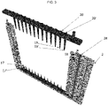
- Figure 2 shows the inner frame (3) of Figure 1 , ready to be inserted in a frame.
- a separation matrix (4) here a gel, has been introduced in molten form through the first plurality of openings (10, 10') into the inner chamber (5).
- the buffer chamber here consisting of an upper compartment (7), a lower compartment (8) and a lateral compartment (9) which are in fluid communication with one another, has been filled with a buffer solution suitable for performing electrophoresis.
- a frame (2) is shown in exploded view, said frame having an opening (18) in its upper end through which an inner frame (not shown) can be inserted.
- the frame (2) comprises a first plurality of first piercing elements (17, 17') in its lower part.
- a second plurality of second piercing elements (19, 19') is provided, which can be fixed on the sides of the frame (2).
- the second piercing elements (19, 19') are here provided with loading channels (20, 20'), which are hollow.
- the frame (2) further comprises means (28) to connect to electrodes.
- the second piercing elements (19, 19') are fixed onto the frame (2).
- the second piercing elements rupture the pierceable seal (14) and go through the second plurality of openings (13, 13') and into the first plurality of openings (10, 10'), so that when samples are loaded in the loading channels (20, 20'), they are effectively introduced in the first plurality of openings (10, 10').
- the first piercing elements (17, 17') upon insertion of the inner frame (3) into the frame (2), go through the bottom layer (12) and are in contact with the buffer in the lower compartment (8), but in this embodiment are not in contact with the inner chamber (5).
- Figure 5B shows an exploded view of the frame (2) and inner frame (3) from figure 5A where the first piercing elements are replaced with an embedded electrode in the bottom of the inner frame (3).
- Figure 6 shows another embodiment of the frame (2), where the first piercing elements (17, 17') also comprise outer channels (23, 23') which extend outside the frame (2) when fixed thereon.
- the first piercing elements (17, 17') are long enough to not only go through the bottom layer (12), but also to be in contact with the separation matrix (4) in the inner chamber (5) through the openings in the lower wall (39).
- the frame (2) comprises means (28) to connect to an electrode, thereby allowing an electrical current to be applied to the outer channels (23, 23') since the first piercing elements are made at least partly of a conductive material; the outer channels thus act as negative electrodes.
- a positive electrode (29) is arranged in the upper compartment (7) of the buffer chamber.
- a first sample reservoir (24) which has wells (25, 25') comprising samples to be analysed by electrophoresis.
- the wells are spaced in such a way that they match the spacing between the first piercing elements (17, 17'), and in particular match the outer channels (23, 23').
- the molecules of interest contained within the samples have a negative charge.
- Application of an electrical current to the first piercing elements and hence to the outer channels (23, 23'), so that these now have a negative charge results in the molecules of interest migrating upwards via the outer channels (23, 23') and continue towards the upper positive electrode (29).
- Such an embodiment thus alleviates the need to load the samples in the outer channels (23, 23') by means of a pipette or liquid handler.
- the electrophoresis procedure as such can then commence, and is in practice performed by reverting the current so that the outer channels (23, 23') now have a positive charge, and the electrode (29) now has a negative charge - thereby allowing migration of the samples through the separation matrix towards the negative electrode (29).
- the pierceable seal (14), which is fluid-tight, allows the user to turn the frame upside down if convenient.
- the second piercing elements (19, 19') are long enough to go through the pierceable seal (14), through the second plurality of openings (13, 13') and to be inserted in the first plurality of openings (10, 10'), and can as shown here come in contact with the separation matrix (4).
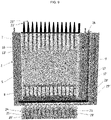
- Figure 8 shows the frame (2) of Figure 7 .
- a first sample reservoir (24) is provided, which has wells (25, 25') comprising samples to be analysed by electrophoresis.
- the wells are spaced in such a way that they match the spacing between the first piercing elements (17, 17'), and in particular match the outer channels (23, 23') of the first piercing elements.
- the frame (2) can be turned upside down, and the outer channels (23", 23'") of the second piercing elements (19, 19') can be inserted in the first sample reservoir (24).
- This allows another type of molecules of interest comprised within the samples, having an opposite charge to the molecules of interest now attached to the outer channels (23, 23') of the first piercing elements (17, 17'), to migrate to the outer channels (23", 23'") of the second piercing elements (19, 19').
- the frame (2) can be turned upside down, and the outer channels (23", 23"') of the second piercing elements (19, 19') can be inserted in the first sample reservoir (24).
- This allows another group of molecules of interest comprised within the samples, having an opposite charge to the molecules of interest now already entered in the separation matrix via outer channels (23, 23') of the first piercing elements (17, 17'), to migrate upwards via the outer channels (23", 23'") of the second piercing elements (19, 19').
- sample reservoir is removed and electrophoreses continue. Migration can be monitored so that the two groups of molecules of interest, having different charges, do not migrate so far that they get intermixed in the separation matrix (4).
- Figure 9 shows a frame (2) comprising an inner frame (3) with a separation matrix (4) in the inner chamber (5).
- an upper electrode (29) is provided in the upper compartment (7) of the buffer chamber which also comprises a lateral compartment (9) and a lower compartment (8).
- the assembly here comprises a first plurality of first piercing elements (17,17') in the lower end, with outer channels (23, 23') protruding out of the frame.
- the first piercing elements go through the fluid-tight bottom layer (12).
- the first piercing elements are electrically connected to another electrode (29') shown here just under the fluid-tight bottom layer.
- the outer channels are electrically connected to a third electrode (29") located just under the second electrode (29').
- the frame (2) comprises means to connect the electrodes (28) to power.
- a sample reservoir (24) comprising twelve wells (25, 25') matching one dimension of a 96-well SBS format.
- the wells comprise a volume of samples comprising molecules of interest.
- the samples comprise whole cells.
- the third electrode (29") is switched off.
- the first electrode (29) and the second electrode (29') can then be turned on, and electrophoretic migration can start.
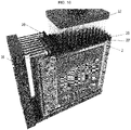
- Figure 10 shows an exploded view of the frame and inner frame of Figure 9 .
- Figure 11 shows an alternative embodiment which, similar to the embodiment of Figures 9 and 10 , can also be used to perform lysis of the samples.
- a second plurality of second piercing elements (19, 19') is here provided in the upper part of the frame. They can be partially inserted in the first plurality of openings (10, 10').
- the second piercing elements comprise loading channels (20, 20') and are connected to an upper electrode (29).
- the second piercing elements can be used to load another set of samples which are introduced in the loading channels, or they can be used to collect the molecules of interest originating from the samples in the sample reservoir (24) once they exit the separation matrix on the upper end. In practice, this is achieved by turning off the power provided to the electrodes (29, 29') to interrupt migration once the molecules of interest exit the upper end of the separation matrix.
- the samples can then easily be collected from the first plurality of openings (10, 10'), for example with a pipette tip. Since the layout of the whole assembly matches an SBS format, the samples can easily be transferred to e.g. a suitable SBS well plate, for example a 96-well plate in an assembly comprising eight frames with 12 lanes each. In the case where different molecules having different sizes reach the first plurality of openings (10, 10') at different times, the continuous monitorability will trigger molecule collection each time a specific group of molecules reaches its respective first plurality of openings (10, 10'),
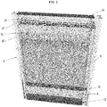
- FIG 12 shows an embodiment of an electrophoresis assembly (1) of the present disclosure.
- the electrophoresis assembly comprises here eight frames (2) connected via an external slidable connection (16), here a ring or cylinder on which each frame is attached.
- the assembly is here shown in the first configuration, where the frames abut each other in a longitudinal direction.
- the eight frames which each comprise 12 openings so that electrophoresis can be performed on 12 lanes, thus match a 96-well SBS format in the first configuration.
- This enables the use of a robot liquid handler (32) to load the samples into the loading channels (20, 20') of the second piercing elements.
- the second piercing elements (19, 19') are connected to an electrode (29), while the first piercing elements (17, 17') are connected to an electrode of opposite charge (29') via the connecting means (28) of the frame (2).
- Figure 13 shows how the electrodes (29, 29') can connect to the connecting means (28) and to the second piercing elements via the connecting means (28').
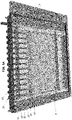
- FIG 14 shows the electrophoresis assembly of Figure 12 while electrophoresis is being performed.
- Each frame can be slid along the external slidable connection (16), and thus become accessible for optical monitoring by optical detection means, here two cameras (31), while electrophoretic separation is progressing.
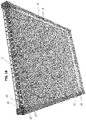
- Figure 15 shows a partial view of the electrophoresis assembly of Figure 12 , here shown without the inner frames, and here shown in the second configuration, where seven frames (2) abut each other in a longitudinal direction, while one frame is accessible for optical monitoring.
- the frames are connected via an external slidable connection (16), along which each frame can slide.
- the frames are equipped with magnets (30, 30'), which help maintain the electrophoresis assembly in the first configuration.
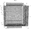
- Figure 16 shows another embodiment of an electrophoresis assembly of the present disclosure.
- the eight frames (2) comprising each 12 openings and 12 loading channels (20, 20') match a 96-well SBS standard.
- a liquid handler (32) can thus be used to introduce samples in the loading channels (20, 20').
- An electrical current is applied to the frames via the connecting means (28) which are connected to electrodes (29, 29').
- Figure 17 shows the electrophoresis assembly of Figure 16 in a second configuration, where not all frames abut each other in a longitudinal direction.
- the frame to be monitored via the detection means here two cameras (40, 40'), can be slid outwards so that optical access to the separation matrix is possible. After image capture, the frame is slid back, and another frame can be slid out for imaging.
- Figure 19 shows a top view of the inner chamber of Figure 18 , flanked by electroblotting membranes (35, 35') and by electroblotting electrodes (22, 22').
- the non-transparent barrier (21) is made of a conductive material, and can thus function as an electrode (shown here as a negative electrode).
- the assembly is arranged in the second configuration before performing electroblotting.
- the inner frame can be removed from the assembly, and electroblotting can be performed on each inner frame individually.
- An electroblotting membrane (35, 35') can be placed on one side of each of the two separation matrices (4, 4'), and another electroblotting electrode (22, 22') of a charge opposite the charge of the electrode (21) (the electroblotting electrodes (22, 22') are here shown with a positive charge) can be used to transfer the molecules of interest from the separation matrix to the electroblotting membrane (35, 35').
- the electroblotting electrodes (22, 22') also have a charge opposite to the charge of the molecules of interest that it is desirable to transfer to the electroblotting membrane.
- the electroblotting electrodes can be in the form of a plate or a sheet made of conductive material and connected to a power supply. Detection of the molecules of interest after transfer to the membrane can then be performed as is known in the art.
- FIG 21 shows how the inner frame of Figure 18 can be used to easily collect molecules of interest from the separation matrix.
- the separation matrix (4) now comprises groups of separated molecules of interest (38, 38').
- a tip (37) can be used to pick up the separated molecules of interest.
- the tip may be a conventional pipette tip, or it may be a conductive tip, e.g. made of a conductive material such as metal, which can incise the separation matrix around the molecules of interest. These can then be aspired within the tip, and transferred for example to a collection reservoir (not shown) for further analysis.
- a current may be applied to the tip having a charge opposite the charge of the molecules of interest, whereby the molecules of interest migrate to the tip.
- a collection reservoir can then be transferred to a collection reservoir.
- this is done by placing the tip in a conductive solution comprised within the collection reservoir and either interrupting the current and/or resuspending the molecules in solution, or inverting the current so that the molecules of interest are submitted to repulsive actions.
Landscapes
- Health & Medical Sciences (AREA)
- Life Sciences & Earth Sciences (AREA)
- Molecular Biology (AREA)
- Chemical & Material Sciences (AREA)
- Chemical Kinetics & Catalysis (AREA)
- Electrochemistry (AREA)
- Physics & Mathematics (AREA)
- Analytical Chemistry (AREA)
- Biochemistry (AREA)
- General Health & Medical Sciences (AREA)
- General Physics & Mathematics (AREA)
- Immunology (AREA)
- Pathology (AREA)
- Investigating, Analyzing Materials By Fluorescence Or Luminescence (AREA)
Priority Applications (1)
| Application Number | Priority Date | Filing Date | Title |
|---|---|---|---|
| EP20210257.0A EP4006536A1 (de) | 2020-11-27 | 2020-11-27 | Elektrophoresegerät und methoden |
Applications Claiming Priority (1)
| Application Number | Priority Date | Filing Date | Title |
|---|---|---|---|
| EP20210257.0A EP4006536A1 (de) | 2020-11-27 | 2020-11-27 | Elektrophoresegerät und methoden |
Publications (1)
| Publication Number | Publication Date |
|---|---|
| EP4006536A1 true EP4006536A1 (de) | 2022-06-01 |
Family
ID=73642632
Family Applications (1)
| Application Number | Title | Priority Date | Filing Date |
|---|---|---|---|
| EP20210257.0A Withdrawn EP4006536A1 (de) | 2020-11-27 | 2020-11-27 | Elektrophoresegerät und methoden |
Country Status (1)
| Country | Link |
|---|---|
| EP (1) | EP4006536A1 (de) |
Cited By (1)
| Publication number | Priority date | Publication date | Assignee | Title |
|---|---|---|---|---|
| KR102645006B1 (ko) * | 2023-06-19 | 2024-03-07 | 이종영 | 전기 영동용 아가로스 겔 제조보관틀 |
Citations (7)
| Publication number | Priority date | Publication date | Assignee | Title |
|---|---|---|---|---|
| US20010037940A1 (en) * | 2000-01-28 | 2001-11-08 | Lih-Bin Shih | Apparatus for horizontal gel electrophoresis and method of using same |
| US20020025278A1 (en) * | 2001-01-09 | 2002-02-28 | Gel Manipulation Apparatus | Gel manipulation apparatus |
| WO2013180641A1 (en) * | 2012-05-31 | 2013-12-05 | Ge Healthcare Bio-Sciences Ab | Method of manufacturing an electrophoresis cassette |
| WO2015079048A1 (en) * | 2013-11-29 | 2015-06-04 | Ge Healthcare Bio-Sciences Ab | Electrophoresis system |
| WO2020079220A1 (en) | 2018-10-18 | 2020-04-23 | Danmarks Tekniske Universitet | Methods for extraction of molecules |
| WO2020079211A1 (en) * | 2018-10-18 | 2020-04-23 | Danmarks Tekniske Universitet | Electrophoresis assembly |
| WO2020146565A1 (en) * | 2019-01-09 | 2020-07-16 | Emd Millipore Corporation | Gel cast cassette and hand cast system |
-
2020
- 2020-11-27 EP EP20210257.0A patent/EP4006536A1/de not_active Withdrawn
Patent Citations (7)
| Publication number | Priority date | Publication date | Assignee | Title |
|---|---|---|---|---|
| US20010037940A1 (en) * | 2000-01-28 | 2001-11-08 | Lih-Bin Shih | Apparatus for horizontal gel electrophoresis and method of using same |
| US20020025278A1 (en) * | 2001-01-09 | 2002-02-28 | Gel Manipulation Apparatus | Gel manipulation apparatus |
| WO2013180641A1 (en) * | 2012-05-31 | 2013-12-05 | Ge Healthcare Bio-Sciences Ab | Method of manufacturing an electrophoresis cassette |
| WO2015079048A1 (en) * | 2013-11-29 | 2015-06-04 | Ge Healthcare Bio-Sciences Ab | Electrophoresis system |
| WO2020079220A1 (en) | 2018-10-18 | 2020-04-23 | Danmarks Tekniske Universitet | Methods for extraction of molecules |
| WO2020079211A1 (en) * | 2018-10-18 | 2020-04-23 | Danmarks Tekniske Universitet | Electrophoresis assembly |
| WO2020146565A1 (en) * | 2019-01-09 | 2020-07-16 | Emd Millipore Corporation | Gel cast cassette and hand cast system |
Cited By (1)
| Publication number | Priority date | Publication date | Assignee | Title |
|---|---|---|---|---|
| KR102645006B1 (ko) * | 2023-06-19 | 2024-03-07 | 이종영 | 전기 영동용 아가로스 겔 제조보관틀 |
Similar Documents
| Publication | Publication Date | Title |
|---|---|---|
| US9719961B2 (en) | Multichannel preparative electrophoresis system | |
| EP2347252B1 (de) | Mehrkanalsystem für die präparative elektrophorese | |
| EP0776700B2 (de) | Verfahren zur Reinigung und Übertragung von sequenzierten DNA-Proben nach Trenn-/Feststellungssystem und Platte dafür | |
| Feng et al. | Microfluidic chip: next-generation platform for systems biology | |
| EP2906935B1 (de) | Molekülfraktionierungsvorrichtung mit seitlicher elution | |
| KR20000068494A (ko) | 생물 샘플의 능동적 제조를 위한 장치 및 방법 | |
| EP2184602A1 (de) | Mikrokanalchip für elektrophorese und verfahren für elektrophorese | |
| EP2234724B1 (de) | Vorrichtung und verfahren zur erkennung von dna-beschädigung | |
| US20120138463A1 (en) | Facile method and apparatus for the analysis of biological macromolecules in two dimensions using common and familiar electrophoresis formats | |
| EP4006536A1 (de) | Elektrophoresegerät und methoden | |
| CN111569958B (zh) | 通过使用ewod器件进行扩散的分子分离 | |
| EP2986978B1 (de) | Minigelkamm | |
| WO2020079211A1 (en) | Electrophoresis assembly | |
| WO2000009998A1 (en) | Novel in-situ loader for electrophoretic gels | |
| CN104031820A (zh) | 核酸的制备装置和核酸的制备方法 | |
| RU2558229C2 (ru) | Набор и способ для приготовления многослойных агарозных блоков на поверхности мини-стекол для микроскопии | |
| JPH07506421A (ja) | 分離されたタンパク質類またはdna/rnaなどの荷電巨大分子類を含有するゲルの電気溶出法およびこれに用いる装置と手段 | |
| JPH10253591A (ja) | サンプルプレートとマルチキャピラリー電気泳動装置 | |
| Yin et al. | Intracellular labeling methods for chip-based capillary electrophoresis | |
| KUBICKI et al. | Dosing and separation of tracking dyes in glass chip for capillary gel electrophoresis | |
| AU2014253462A1 (en) | Apparatus and method for detecting DNA damage | |
| JP2000137021A (ja) | サンプルプレートとマルチキャピラリー電気泳動装置 |
Legal Events
| Date | Code | Title | Description |
|---|---|---|---|
| PUAI | Public reference made under article 153(3) epc to a published international application that has entered the european phase |
Free format text: ORIGINAL CODE: 0009012 |
|
| STAA | Information on the status of an ep patent application or granted ep patent |
Free format text: STATUS: THE APPLICATION HAS BEEN PUBLISHED |
|
| AK | Designated contracting states |
Kind code of ref document: A1 Designated state(s): AL AT BE BG CH CY CZ DE DK EE ES FI FR GB GR HR HU IE IS IT LI LT LU LV MC MK MT NL NO PL PT RO RS SE SI SK SM TR |
|
| STAA | Information on the status of an ep patent application or granted ep patent |
Free format text: STATUS: THE APPLICATION IS DEEMED TO BE WITHDRAWN |
|
| 18D | Application deemed to be withdrawn |
Effective date: 20221202 |