EP4004440B1 - Doppelverteilungslinse für eine leuchte - Google Patents
Doppelverteilungslinse für eine leuchte Download PDFInfo
- Publication number
- EP4004440B1 EP4004440B1 EP20747403.2A EP20747403A EP4004440B1 EP 4004440 B1 EP4004440 B1 EP 4004440B1 EP 20747403 A EP20747403 A EP 20747403A EP 4004440 B1 EP4004440 B1 EP 4004440B1
- Authority
- EP
- European Patent Office
- Prior art keywords
- lens
- luminaire
- light
- housing
- light source
- Prior art date
- Legal status (The legal status is an assumption and is not a legal conclusion. Google has not performed a legal analysis and makes no representation as to the accuracy of the status listed.)
- Active
Links
Images


Classifications
-
- F—MECHANICAL ENGINEERING; LIGHTING; HEATING; WEAPONS; BLASTING
- F21—LIGHTING
- F21S—NON-PORTABLE LIGHTING DEVICES; SYSTEMS THEREOF; VEHICLE LIGHTING DEVICES SPECIALLY ADAPTED FOR VEHICLE EXTERIORS
- F21S8/00—Lighting devices intended for fixed installation
- F21S8/02—Lighting devices intended for fixed installation of recess-mounted type, e.g. downlighters
- F21S8/026—Lighting devices intended for fixed installation of recess-mounted type, e.g. downlighters intended to be recessed in a ceiling or like overhead structure, e.g. suspended ceiling
-
- F—MECHANICAL ENGINEERING; LIGHTING; HEATING; WEAPONS; BLASTING
- F21—LIGHTING
- F21V—FUNCTIONAL FEATURES OR DETAILS OF LIGHTING DEVICES OR SYSTEMS THEREOF; STRUCTURAL COMBINATIONS OF LIGHTING DEVICES WITH OTHER ARTICLES, NOT OTHERWISE PROVIDED FOR
- F21V13/00—Producing particular characteristics or distribution of the light emitted by means of a combination of elements specified in two or more of main groups F21V1/00 - F21V11/00
- F21V13/02—Combinations of only two kinds of elements
- F21V13/04—Combinations of only two kinds of elements the elements being reflectors and refractors
-
- F—MECHANICAL ENGINEERING; LIGHTING; HEATING; WEAPONS; BLASTING
- F21—LIGHTING
- F21V—FUNCTIONAL FEATURES OR DETAILS OF LIGHTING DEVICES OR SYSTEMS THEREOF; STRUCTURAL COMBINATIONS OF LIGHTING DEVICES WITH OTHER ARTICLES, NOT OTHERWISE PROVIDED FOR
- F21V17/00—Fastening of component parts of lighting devices, e.g. shades, globes, refractors, reflectors, filters, screens, grids or protective cages
- F21V17/02—Fastening of component parts of lighting devices, e.g. shades, globes, refractors, reflectors, filters, screens, grids or protective cages with provision for adjustment
-
- F—MECHANICAL ENGINEERING; LIGHTING; HEATING; WEAPONS; BLASTING
- F21—LIGHTING
- F21V—FUNCTIONAL FEATURES OR DETAILS OF LIGHTING DEVICES OR SYSTEMS THEREOF; STRUCTURAL COMBINATIONS OF LIGHTING DEVICES WITH OTHER ARTICLES, NOT OTHERWISE PROVIDED FOR
- F21V17/00—Fastening of component parts of lighting devices, e.g. shades, globes, refractors, reflectors, filters, screens, grids or protective cages
- F21V17/06—Fastening of component parts of lighting devices, e.g. shades, globes, refractors, reflectors, filters, screens, grids or protective cages the fastening being onto or by the lampholder
-
- F—MECHANICAL ENGINEERING; LIGHTING; HEATING; WEAPONS; BLASTING
- F21—LIGHTING
- F21V—FUNCTIONAL FEATURES OR DETAILS OF LIGHTING DEVICES OR SYSTEMS THEREOF; STRUCTURAL COMBINATIONS OF LIGHTING DEVICES WITH OTHER ARTICLES, NOT OTHERWISE PROVIDED FOR
- F21V17/00—Fastening of component parts of lighting devices, e.g. shades, globes, refractors, reflectors, filters, screens, grids or protective cages
- F21V17/10—Fastening of component parts of lighting devices, e.g. shades, globes, refractors, reflectors, filters, screens, grids or protective cages characterised by specific fastening means or way of fastening
- F21V17/16—Fastening of component parts of lighting devices, e.g. shades, globes, refractors, reflectors, filters, screens, grids or protective cages characterised by specific fastening means or way of fastening by deformation of parts; Snap action mounting
- F21V17/164—Fastening of component parts of lighting devices, e.g. shades, globes, refractors, reflectors, filters, screens, grids or protective cages characterised by specific fastening means or way of fastening by deformation of parts; Snap action mounting the parts being subjected to bending, e.g. snap joints
-
- F—MECHANICAL ENGINEERING; LIGHTING; HEATING; WEAPONS; BLASTING
- F21—LIGHTING
- F21V—FUNCTIONAL FEATURES OR DETAILS OF LIGHTING DEVICES OR SYSTEMS THEREOF; STRUCTURAL COMBINATIONS OF LIGHTING DEVICES WITH OTHER ARTICLES, NOT OTHERWISE PROVIDED FOR
- F21V5/00—Refractors for light sources
- F21V5/02—Refractors for light sources of prismatic shape
-
- F—MECHANICAL ENGINEERING; LIGHTING; HEATING; WEAPONS; BLASTING
- F21—LIGHTING
- F21V—FUNCTIONAL FEATURES OR DETAILS OF LIGHTING DEVICES OR SYSTEMS THEREOF; STRUCTURAL COMBINATIONS OF LIGHTING DEVICES WITH OTHER ARTICLES, NOT OTHERWISE PROVIDED FOR
- F21V5/00—Refractors for light sources
- F21V5/04—Refractors for light sources of lens shape
-
- F—MECHANICAL ENGINEERING; LIGHTING; HEATING; WEAPONS; BLASTING
- F21—LIGHTING
- F21Y—INDEXING SCHEME ASSOCIATED WITH SUBCLASSES F21K, F21L, F21S and F21V, RELATING TO THE FORM OR THE KIND OF THE LIGHT SOURCES OR OF THE COLOUR OF THE LIGHT EMITTED
- F21Y2115/00—Light-generating elements of semiconductor light sources
- F21Y2115/10—Light-emitting diodes [LED]
Definitions
- Embodiments of the technology relate generally to luminaires and more particularly to a dual distribution lens for a luminaire.
- Luminaires often include multiple components, such as a housing, a light source, a reflector, a lens, and a trim.
- sellers can offer customers options for the various components.
- a seller of luminaires can offer customers different types of trims that provide different appearances.
- Sellers of luminaires also can offer different types of lenses that provide different distributions of light.
- the seller can offer customers a first type of lens that provides a wide distribution of light from the luminaire.
- the seller can offer a second type of lens that modifies the light exiting the luminaire to achieve a more narrow distribution of light.
- the seller may offer a variety of lenses with each luminaire to provide a variety of different distributions.
- offering a variety of different lenses for sale with a luminaire adds expense because the manufacturer must create tooling for making each variety of lens. Additionally, offering a variety of lenses for sale with a luminaire adds supply chain costs and challenges because the seller must keep each variation of the lens in stock. Accordingly, it would be beneficial to provide a solution that allows customers to choose different light distributions while also minimizing the number of different lenses that are required to be manufactured and held in stock for sale to customers.
- U.S. patent publication 2008/0298071 discloses an LED lighting device having a polygon surface shaped light-pervious plate is disposed at the open side and light emitted from the LED is capable of being spread outward through the polygon surface shaped light-pervious plate.
- U.S. patent publication 2008/0137347 discloses a light fixture structure comprises a housing defining an opening and an first attachment element comprising a nose element, a hook element and a connection region, and optionally further comprising a diffuser engaging a first portion of the hook element, and/or an accessory which engages a second portion of the hook element.
- Japanese patent publication JP2015088349 discloses an LED lighting device with a lens located at the end of a reflector to close the opening, where the lens member includes a protruding part, which controls light distribution, protruding toward the LED light source and disposed at a periphery of the lens member.
- Japanese patent publication JP2015062187 discloses an LED lighting apparatus with a lens cassette holder with multiple slits to relocate a lens, or install the lens upside down.
- a luminaire comprises a housing, a light emitting diode light source disposed within the housing, a reflector disposed within the housing, and a lens disposed within the housing.
- the reflector is oriented within the housing to reflect a portion of light emitted from the light emitting diode light source.
- the lens comprises a first side and a second side, wherein at least one of the first side and the second side comprises a pattern of optical features.
- the lens further comprises an attachment feature configured to attach the lens to the luminaire either in a first position with the first side facing the light emitting diode light source or in a second position with the second side facing the light emitting diode light source.
- a luminaire comprises a housing, a light emitting diode light source disposed within the housing, and a lens disposed within the housing.
- the lens comprises a first side and a second side, wherein at least one of the first side and the second side comprises a pattern of optical features.
- the lens further comprises an attachment feature configured to attach the lens to the luminaire either in a first position with the first side facing the light emitting diode light source or in a second position with the second side facing the light emitting diode light source.
- the example embodiments described herein relate to a luminaire having a housing and a lens disposed within the housing.
- the lens comprises two different broad surfaces. When the lens is oriented in the luminaire housing with the first broad surface facing the light source, the lens emits light having a first distribution. However, when the lens is removed, flipped over, and inserted back into the luminaire housing so that the lens is oriented with the opposite second broad surface facing the light source of the luminaire, the lens emits light having a second distribution that is different from the first distribution.
- the example embodiments illustrated in the attached figures pertain to a recessed luminaire. However, it should be understood that the example embodiments described herein are representative and the disclosure can be applied to other types of light fixtures, including but not limited to surface mounted light fixtures, pendant light fixtures, troffer light fixtures, highbay light fixtures, outdoor light fixtures, and flood light fixtures.
- the example light fixtures are subject to meeting certain standards and/or requirements.
- NEC National Electric Code
- NEMA National Electrical Manufacturers Association
- IEC International Electrotechnical Commission
- FCC Federal Communication Commission
- IEEE Institute of Electrical and Electronics Engineers
- UL Underwriters Laboratories
- any light fixture components e.g., housings, reflectors, lenses, trim assemblies
- a single piece e.g., as from a mold, injection mold, die cast, 3-D printing process, extrusion process, stamping process, or other prototype methods.
- a luminaire or components thereof
- the multiple pieces can be mechanically coupled to each other using one or more of a number of coupling methods, including but not limited to epoxy, welding, fastening devices, compression fittings, mating threads, and slotted fittings.
- One or more pieces that are mechanically coupled to each other can be coupled to each other in one or more of a number of ways, including but not limited to fixedly, hingedly, removeably, slidably, and threadably.
- An attachment feature (including a complementary attachment feature) as described herein can allow one or more components and/or portions of an example lens, reflector, housing or other component of a light fixture to become coupled, directly or indirectly, to another portion or other component of a light fixture.
- An attachment feature can include, but is not limited to, a flange, a snap, Velcro, a clamp, a portion of a hinge, an aperture, a recessed area, a protrusion, a slot, a spring clip, a tab, a detent, and mating threads.
- One portion of an example lens can be coupled to a light fixture by the direct use of one or more attachment features.
- a portion of a light fixture can be coupled using one or more independent devices that interact with one or more attachment features disposed on a component of the lens, light fixture, or other component of a light fixture.
- independent devices can include, but are not limited to, a pin, a hinge, a fastening device (e.g., a bolt, a screw, a rivet), epoxy, glue, adhesive, tape, and a spring.
- One attachment feature described herein can be the same as, or different than, one or more other attachment features described herein.
- a complementary attachment feature also sometimes called a corresponding attachment feature
- a complementary attachment feature as described herein can be a coupling feature that mechanically couples, directly or indirectly, with another coupling feature.
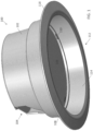
- Figure 1 shows a perspective view of luminaire 100 with a view up into the light emitting aperture 112.
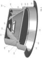
- Figure 2 shows a cross-sectional view of luminaire 100 with the cross section taken along a vertical plane passing through the luminaire 100.
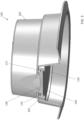
- Figure 3 shows another cross-sectional view of luminaire 100 with the cross section taken along another vertical plane passing through the luminaire 100.
- the example luminaire 100 is a recessed luminaire for installation in a ceiling.
- the recessed luminaire 100 can be mounted using any of a variety of known methods including but not limited to fasteners, torsion springs, friction clips, and mounting brackets.
- the primary components of the example luminaire 100 comprise a housing 102, a light source 125, a reflector 130, and a lens 106.
- the housing 102 comprises an interior surface 114 which can be reflective so as to reflect light incident on the interior surface 114.
- the lower edge of the interior surface 114 defines the light emitting aperture 112.
- the housing 102 further comprises a housing flange 118 extending from the lower edge of the interior surface 114 of the housing 102.
- the housing flange 118 can cover any gaps which may exist between the luminaire 100 and the surface (e.g., a ceiling) in which the luminaire 100 is mounted.
- the housing 102 of example luminaire 100 also comprises an optional service aperture 104.
- the service aperture 104 provides access to the interior of the housing 102 and can be used, for example, to make wiring connections when installing the luminaire 100.
- the light source illustrated in Figure 2 is a chip on board LED light source 125, which is mounted to the interior upper surface of housing 102. It should be understood that in alternate embodiments other types of light sources can be implemented including but not limited to a single LED, an array of LEDs, and one or more organic LEDs. Additionally, in alternate embodiments, the light source can be located in other positions within the luminaire.
- the reflector 130 is mounted within the housing 102 near the interior upper surface and near the light source 125.
- the reflector 130 is generally conical in shape and comprises an entrance opening proximal to the light source 125 and an exit opening distal from the light source 125.
- the reflector 130 receives some of the light emitted by the light source 125 and reflects the incident light down toward the light emitting aperture 112.
- the housing 102 and the reflector 130 are shown as distinct components in the example of Figures 1-3 , it should be understood that the dual distribution lens can be implemented in a variety of luminaires which may have different housings and may or may not include a reflector.
- the separate reflector can be omitted and the interior of the housing can comprise a reflective surface.
- a reflective surface within the luminaire may be unnecessary.
- the reflector 130 comprises a reflector flange 131 which extends outward from the bottom edge of the reflector 130.
- the reflector flange 131 retains the dual distribution lens 106 within the housing 102.
- the dual distribution lens 106 comprises a first broad surface (or first side) 122, a second broad surface (or second side) 120, and a rim 107 about the perimeter of the lens 106.
- the rim 107 of the lens 106 comprises one or more attachment features for securing the lens 106 within the housing 102.
- the attachment features are tabs 110 and 111 disposed along the interior surface of the rim 107.
- the reflector flange 131 comprises one or more gaps 132 through which tabs 110 or tabs 111 can fit.
- the tabs 111 of the rim 107 are inserted into the gaps 132 of the reflector flange 131 and the lens 106 is rotated so that the tabs 111 rest on the upper side of the reflector flange 131.
- the lens 106 is positioned with the tabs 111 passing through the gaps 132 and the lens 106 is rotated, the lens 106 is secured by the reflector flange 131 within the luminaire in the first orientation.
- the first broad surface 122 of the lens comprises a pattern of optical features which makes the first broad surface 122 different from the second broad surface 120.
- the lens 106 provides a first distribution of light created by the light from the light source 125 encountering the pattern of optical features on the first broad surface 122 before the light passes through the lens 106.
- the lens 106 can comprise an indicator 108, such as the word "WIDE", on one or both of the first broad surface 122 and the second broad surface 120 indicating the type of light distribution associated with the orientation of the lens 106.
- the light distribution emitted by the luminaire 100 can be changed by reorienting or flipping over the same lens 106 without the need for another lens.
- two different light distributions can be achieved with the single lens having different surfaces on the opposite broad surfaces of the lens.
- the lens 106 can be rotated so that the tabs 111 pass back through the gaps 132 in the reflector flange 131 and so that the lens 106 can be removed from the housing 102. Once removed, the lens 106 can be flipped over so that the second broad surface 120 faces upward toward the light source 125.
- the lens 106 can then be inserted back into the housing 102 so that the tabs 110 on the second side of the lens 106 are inserted into the gaps 132 in the reflector flange 131. Once the tabs 110 are inserted into the gaps 132, the lens 106 is rotated so that the tabs 110 rest on top of the reflector flange 131 and the lens 106 is retained in place in a second orientation within the luminaire 100.
- the second broad surface 120 is different than the first broad surface 122 so that a different light distribution is emitted by the luminaire 100 when the lens 106 is in the second orientation.
- the tabs 110 and 111 and the reflector flange 131 are merely one example of attachment features for securing the lens 106 within the luminaire 100 according to the invention.
- the tabs can be located on the outer surface of the rim 107 and the tabs can attach to a ledge on the interior surface of the housing 102.
- the bottom of the reflector can be wider than the lens with a reflector flange extending inward and the tabs can be located on the outer surface of the rim 107 such that they rest on the inward extending reflector flange.
- the tabs can be replaced by threads, detents, or a variety of other types of attachment features that allow the lens to be easily attached to and detached from the luminaire so that the lens can be easily flipped over from the first orientation to the second orientation.
- the lens can be located at different positions with respect to the luminaire.
- the lens 106 recessed in the housing 102 in other embodiments, the lens can be located adjacent the housing flange 118 at the light emitting aperture 112.
- FIG. 4 two ray trace diagrams are provided illustrating the different light distributions that can be achieved by reorienting the lens 106 from the first orientation to the second orientation.
- the ray trace diagrams shown in Figures 4 and 5 have been simplified from the example luminaire of Figures 1-3 in that the housing 102, reflector 130, and lens rim 107 are not shown, the light source 125 has been simplified to a point source, and only a portion of the light rays are shown.
- Figure 4 shows lens 106 with the first broad surface 122 facing the light source 125 and the second broad surface 120 facing away from the light source 125.
- An axis 140 is shown passing through the center of the lens 106.
- the pattern of optical features on the first broad surface 122 causes a substantial portion of the light rays emitted from the light source 125 to diverge.
- the diverging light rays 144 constitute a majority of the light rays and the converging light rays 142 a minority of the light rays, thereby producing a relatively wide light distribution.
- Figure 5 shows lens 106 after being reoriented or flipped over, as described above, so that the first broad surface 122 faces away from the light source 125 and the second broad surface 120 faces the light source 125.
- the light rays emitted from the light source 125 do not encounter the pattern of optical features on the first side 122 until after the light rays pass through the lens 106.
- the example dual distribution lens 106 illustrated in Figures 1-5 has a pattern of optical features on the first broad surface 122 and a smooth surface on the second broad surface 120.
- the pattern of optical features on the first broad surface 122 has features with the shape of a four-sided pyramid. However, to achieve other light distributions, the features can have other shapes including but not limited to conic, tetrahedral, or hexagonal. Additionally, in other example embodiments, instead of a smooth surface, the second broad surface 120 of the lens 106 can have a pattern of optical features that is different from the pattern of optical features on the first broad surface 122. The differing patterns of optical features on opposite sides of the lens can also be used to achieve different light distributions.
- first broad surface 122 While the pattern of optical features on the first broad surface 122 are shown extending from the lens 106, it should be understood that in other embodiments, other types of features affecting light distribution can be embedded within the lens proximal to one or both of the first side and the second side of the lens.
Landscapes
- Engineering & Computer Science (AREA)
- General Engineering & Computer Science (AREA)
- Non-Portable Lighting Devices Or Systems Thereof (AREA)
- Securing Globes, Refractors, Reflectors Or The Like (AREA)
Claims (12)
- Leuchte (100), umfassend:ein Gehäuse (102);eine Leuchtdiodenlichtquelle (125), die innerhalb des Gehäuses angeordnet ist;einen Reflektor (130), der innerhalb des Gehäuses angeordnet und so ausgerichtet ist, dass er einen Teil des Lichts von der Leuchtdiodenlichtquelle reflektiert; undeine Linse (106), die innerhalb des Gehäuses angeordnet ist, wobei die Linse eine erste Seite (122) und eine zweite Seite (120) umfasst, wobei mindestens eine der ersten Seite und der zweiten Seite ein Muster optischer Merkmale umfasst, wobei die Linse ein Befestigungsmerkmal umfasst, das die Linse am Reflektor befestigt, wobei das Befestigungsmerkmal dazu konfiguriert ist, die Linse in einer ersten Position, wobei die erste Seite der Leuchtdiodenlichtquelle zugewandt ist, und in einer zweiten Position, wobei die zweite Seite der Leuchtdiodenlichtquelle zugewandt ist, an der Leuchte zu befestigen,dadurch gekennzeichnet, dass das Befestigungsmerkmal umfasst: eine erste Vielzahl von Laschen (110) in der Nähe einer ersten Kante eines Randes (107) der Linse, wobei, wenn die Linse in der ersten Position an der Leuchte befestigt ist, die erste Vielzahl von Laschen in entsprechende Aussparungen (132) im Reflektor passt; undeine zweite Vielzahl von Laschen (111) in der Nähe einer zweiten Kante des Linsenrands, wobei, wenn die Linse in der zweiten Position an der Leuchte angebracht ist, die zweite Vielzahl von Laschen in die entsprechenden Aussparungen (132) im Reflektor passt.
- Leuchte nach Anspruch 1, wobei die Linse, wenn sie in der ersten Position angebracht ist, bewirkt, dass ein Großteil des Lichts von der Leuchtdiodenlichtquelle beim Durchgang durch die Linse divergiert.
- Leuchte nach Anspruch 1, wobei der Reflektor ein integraler Bestandteil des Gehäuses ist.
- Leuchte nach Anspruch 1, wobei das Befestigungsmerkmal am Rand der Linse angeordnet ist.
- Leuchte nach Anspruch 4, wobei das Befestigungsmerkmal an einer Innenfläche des Linsenrands angeordnet ist.
- Leuchte nach Anspruch 4, wobei das Befestigungsmerkmal an einer Außenfläche des Linsenrands angeordnet ist.
- Leuchte nach Anspruch 1, wobei das Muster optischer Merkmale auf der ersten Seite der Linse angeordnet ist und die zweite Seite der Linse glatt ist.
- Leuchte nach Anspruch 1, wobei die Linse, wenn sie in der ersten Position an der Leuchte angebracht ist, bewirkt, dass ein Großteil des Lichts von der Leuchtdiodenlichtquelle beim Durchgang durch die Linse divergiert.
- Leuchte nach Anspruch 1, wobei jedes optische Merkmal des Musters optischer Merkmale eine Form aufweist, die aus der Gruppe ausgewählt ist, die aus pyramidenförmig, kegelförmig, tetraedrisch und sechseckig besteht.
- Leuchte nach Anspruch 1, wobei die erste Seite der Linse ein erstes Muster optischer Merkmale umfasst und die zweite Seite der Linse ein zweites Muster optischer Merkmale umfasst.
- Leuchte nach Anspruch 1, ferner umfassend eine Blende (112), durch die das Licht von der Leuchtdiodenlichtquelle die Leuchte verlässt, nachdem es durch die Linse gegangen ist.
- Leuchte nach Anspruch 11, wobei die Linse zwischen der Blende und der Leuchtdiodenlichtquelle angeordnet ist.
Applications Claiming Priority (2)
| Application Number | Priority Date | Filing Date | Title |
|---|---|---|---|
| US16/528,313 US10753572B1 (en) | 2019-07-31 | 2019-07-31 | Dual distribution lens for a luminaire |
| PCT/EP2020/071232 WO2021018876A1 (en) | 2019-07-31 | 2020-07-28 | Dual distribution lens for a luminaire |
Publications (3)
| Publication Number | Publication Date |
|---|---|
| EP4004440A1 EP4004440A1 (de) | 2022-06-01 |
| EP4004440C0 EP4004440C0 (de) | 2024-12-25 |
| EP4004440B1 true EP4004440B1 (de) | 2024-12-25 |
Family
ID=71846404
Family Applications (1)
| Application Number | Title | Priority Date | Filing Date |
|---|---|---|---|
| EP20747403.2A Active EP4004440B1 (de) | 2019-07-31 | 2020-07-28 | Doppelverteilungslinse für eine leuchte |
Country Status (6)
| Country | Link |
|---|---|
| US (2) | US10753572B1 (de) |
| EP (1) | EP4004440B1 (de) |
| JP (1) | JP7604453B2 (de) |
| CN (1) | CN114174717A (de) |
| ES (1) | ES2998762T3 (de) |
| WO (1) | WO2021018876A1 (de) |
Families Citing this family (2)
| Publication number | Priority date | Publication date | Assignee | Title |
|---|---|---|---|---|
| US10753572B1 (en) * | 2019-07-31 | 2020-08-25 | Signify Holding B.V. | Dual distribution lens for a luminaire |
| GB2599076B (en) * | 2020-09-08 | 2025-07-23 | Iq Structures Sro | Modular luminaires |
Family Cites Families (29)
| Publication number | Priority date | Publication date | Assignee | Title |
|---|---|---|---|---|
| US6079844A (en) * | 1997-06-10 | 2000-06-27 | The University Of British Columbia | High efficiency high intensity backlighting of graphic displays |
| US6379012B1 (en) | 2000-06-20 | 2002-04-30 | Draper, Inc. | Overhead projector mount system |
| JP2002049324A (ja) * | 2000-07-31 | 2002-02-15 | Nippon Seiki Co Ltd | バックライト装置 |
| TWI293707B (en) * | 2004-06-08 | 2008-02-21 | Prodisc Technology Inc | Liquid crystal display and backlight module |
| TWI291573B (en) * | 2004-12-24 | 2007-12-21 | Prodisc Technology Inc | Liquid crystal display and backlight module |
| US7195359B1 (en) | 2005-01-28 | 2007-03-27 | Conti Mario W | Framing projector with adjustable shutter |
| EP2100076B1 (de) * | 2006-11-30 | 2014-08-13 | Cree, Inc. | Leuchten, beleuchtungsvorrichtungen und bestandteile dafür |
| US20080298071A1 (en) | 2007-06-03 | 2008-12-04 | Ching-Hang Shen | Led lighting device (2) |
| JP2009048920A (ja) | 2007-08-22 | 2009-03-05 | Tokai Kogaku Kk | 照明装置 |
| US8446288B2 (en) | 2008-10-15 | 2013-05-21 | Panasonic Corporation | Light projection device |
| US7993025B2 (en) * | 2009-12-01 | 2011-08-09 | Davinci Industrial Inc. | LED lamp |
| US8947349B1 (en) | 2010-03-02 | 2015-02-03 | Rawles Llc | Projecting content onto a display medium |
| JP2013008620A (ja) | 2011-06-27 | 2013-01-10 | Mitsubishi Electric Corp | 照明器具 |
| CN102853325A (zh) * | 2011-06-28 | 2013-01-02 | 海洋王照明科技股份有限公司 | 灯具 |
| US9091426B2 (en) * | 2012-03-29 | 2015-07-28 | Abl Ip Holding Llc | Light assembly |
| US8882311B2 (en) * | 2012-04-27 | 2014-11-11 | Cree, Inc. | Lens assembly for lighting fixture |
| US20130322091A1 (en) * | 2012-06-01 | 2013-12-05 | Kenneth W. Honeycutt | Lamp accent assembly and method |
| US9316889B2 (en) | 2012-08-07 | 2016-04-19 | Nook Digital, Llc | Front projection eReader system |
| US9134006B2 (en) | 2012-10-22 | 2015-09-15 | Cree, Inc. | Beam shaping lens and LED lighting system using same |
| JP3187902U (ja) | 2013-10-10 | 2013-12-19 | ミネベア株式会社 | 照明装置 |
| JP6311856B2 (ja) | 2013-10-31 | 2018-04-18 | パナソニックIpマネジメント株式会社 | 照明器具 |
| US9236345B2 (en) | 2014-03-24 | 2016-01-12 | Globalfoundries Inc. | Oxide mediated epitaxial nickel disilicide alloy contact formation |
| JP5885807B2 (ja) | 2014-10-31 | 2016-03-16 | 三菱電機株式会社 | Led照明器具 |
| US9874325B2 (en) | 2015-04-10 | 2018-01-23 | Simply Leds, Llc | Configurable overhead light |
| CN205535397U (zh) * | 2016-04-29 | 2016-08-31 | 厦门市益光照明科技有限公司 | 便于组装的筒灯 |
| CN106678558A (zh) * | 2016-08-31 | 2017-05-17 | 厦门益光照明科技股份有限公司 | 一种正装或倒装的led透镜和led照明灯具 |
| CN106678726A (zh) | 2016-12-29 | 2017-05-17 | 安徽科发信息科技有限公司 | 一种产生立体灯光效果的灯具 |
| CN110462453A (zh) * | 2017-04-03 | 2019-11-15 | 昕诺飞控股有限公司 | 固态照明的宽光束角度创建 |
| US10753572B1 (en) * | 2019-07-31 | 2020-08-25 | Signify Holding B.V. | Dual distribution lens for a luminaire |
-
2019
- 2019-07-31 US US16/528,313 patent/US10753572B1/en active Active
-
2020
- 2020-07-28 ES ES20747403T patent/ES2998762T3/es active Active
- 2020-07-28 EP EP20747403.2A patent/EP4004440B1/de active Active
- 2020-07-28 CN CN202080055037.8A patent/CN114174717A/zh active Pending
- 2020-07-28 US US17/630,781 patent/US11846414B2/en active Active
- 2020-07-28 WO PCT/EP2020/071232 patent/WO2021018876A1/en not_active Ceased
- 2020-07-28 JP JP2022506300A patent/JP7604453B2/ja active Active
Also Published As
| Publication number | Publication date |
|---|---|
| EP4004440C0 (de) | 2024-12-25 |
| JP2022542608A (ja) | 2022-10-05 |
| EP4004440A1 (de) | 2022-06-01 |
| US10753572B1 (en) | 2020-08-25 |
| US20220268422A1 (en) | 2022-08-25 |
| JP7604453B2 (ja) | 2024-12-23 |
| ES2998762T3 (en) | 2025-02-21 |
| WO2021018876A1 (en) | 2021-02-04 |
| US11846414B2 (en) | 2023-12-19 |
| CN114174717A (zh) | 2022-03-11 |
Similar Documents
| Publication | Publication Date | Title |
|---|---|---|
| US10677429B2 (en) | LED module with mounting brackets | |
| US9702516B1 (en) | Light-emitting diode based recessed light fixtures | |
| US10436976B2 (en) | Ribs for sealing and aligning an outdoor lightguide luminaire | |
| US20090290343A1 (en) | Lighting fixture | |
| US20190301727A1 (en) | Loudspeaker luminaire with light pipe | |
| EP4004440B1 (de) | Doppelverteilungslinse für eine leuchte | |
| US11047554B2 (en) | Adjustable trim collar for a light fixture | |
| JP5016711B2 (ja) | 照明装置 | |
| US10393344B2 (en) | Uplight reflector for luminaires | |
| US10072806B1 (en) | Luminaire downlight | |
| US20110019429A1 (en) | Cover and lighting apparatus including the cover | |
| CN218645321U (zh) | 灯具 | |
| CN103453462A (zh) | 光源单元及照明器具 | |
| CN216480786U (zh) | 一种防眩光照明设备 | |
| CN210921130U (zh) | 一种无螺钉徒手组装的平板天花灯 | |
| JP5570637B2 (ja) | カバー及び該カバーを備える照明装置 | |
| EP3260772B1 (de) | Installationsmechanismus für led-scheinwerfer | |
| US10794570B2 (en) | Optical element, light source module and lighting device | |
| JP6990149B2 (ja) | 照明器具 | |
| CN109973830A (zh) | 快装光源模组及灯具 | |
| JP2021044258A (ja) | 照明器具 | |
| JP2013258092A (ja) | 照明装置 | |
| JP2016051499A (ja) | 照明器具 | |
| JP2013196789A (ja) | 照明装置 | |
| JP2011204548A (ja) | 照明器具 |
Legal Events
| Date | Code | Title | Description |
|---|---|---|---|
| STAA | Information on the status of an ep patent application or granted ep patent |
Free format text: STATUS: UNKNOWN |
|
| STAA | Information on the status of an ep patent application or granted ep patent |
Free format text: STATUS: THE INTERNATIONAL PUBLICATION HAS BEEN MADE |
|
| PUAI | Public reference made under article 153(3) epc to a published international application that has entered the european phase |
Free format text: ORIGINAL CODE: 0009012 |
|
| STAA | Information on the status of an ep patent application or granted ep patent |
Free format text: STATUS: REQUEST FOR EXAMINATION WAS MADE |
|
| 17P | Request for examination filed |
Effective date: 20220228 |
|
| AK | Designated contracting states |
Kind code of ref document: A1 Designated state(s): AL AT BE BG CH CY CZ DE DK EE ES FI FR GB GR HR HU IE IS IT LI LT LU LV MC MK MT NL NO PL PT RO RS SE SI SK SM TR |
|
| DAV | Request for validation of the european patent (deleted) | ||
| DAX | Request for extension of the european patent (deleted) | ||
| GRAP | Despatch of communication of intention to grant a patent |
Free format text: ORIGINAL CODE: EPIDOSNIGR1 |
|
| STAA | Information on the status of an ep patent application or granted ep patent |
Free format text: STATUS: GRANT OF PATENT IS INTENDED |
|
| INTG | Intention to grant announced |
Effective date: 20240719 |
|
| GRAS | Grant fee paid |
Free format text: ORIGINAL CODE: EPIDOSNIGR3 |
|
| GRAA | (expected) grant |
Free format text: ORIGINAL CODE: 0009210 |
|
| STAA | Information on the status of an ep patent application or granted ep patent |
Free format text: STATUS: THE PATENT HAS BEEN GRANTED |
|
| AK | Designated contracting states |
Kind code of ref document: B1 Designated state(s): AL AT BE BG CH CY CZ DE DK EE ES FI FR GB GR HR HU IE IS IT LI LT LU LV MC MK MT NL NO PL PT RO RS SE SI SK SM TR |
|
| REG | Reference to a national code |
Ref country code: GB Ref legal event code: FG4D |
|
| REG | Reference to a national code |
Ref country code: CH Ref legal event code: EP |
|
| REG | Reference to a national code |
Ref country code: DE Ref legal event code: R096 Ref document number: 602020043679 Country of ref document: DE |
|
| REG | Reference to a national code |
Ref country code: IE Ref legal event code: FG4D |
|
| REG | Reference to a national code |
Ref country code: ES Ref legal event code: FG2A Ref document number: 2998762 Country of ref document: ES Kind code of ref document: T3 Effective date: 20250221 |
|
| U01 | Request for unitary effect filed |
Effective date: 20250123 |
|
| U07 | Unitary effect registered |
Designated state(s): AT BE BG DE DK EE FI FR IT LT LU LV MT NL PT RO SE SI Effective date: 20250129 |
|
| PG25 | Lapsed in a contracting state [announced via postgrant information from national office to epo] |
Ref country code: HR Free format text: LAPSE BECAUSE OF FAILURE TO SUBMIT A TRANSLATION OF THE DESCRIPTION OR TO PAY THE FEE WITHIN THE PRESCRIBED TIME-LIMIT Effective date: 20241225 |
|
| PG25 | Lapsed in a contracting state [announced via postgrant information from national office to epo] |
Ref country code: NO Free format text: LAPSE BECAUSE OF FAILURE TO SUBMIT A TRANSLATION OF THE DESCRIPTION OR TO PAY THE FEE WITHIN THE PRESCRIBED TIME-LIMIT Effective date: 20250325 |
|
| PG25 | Lapsed in a contracting state [announced via postgrant information from national office to epo] |
Ref country code: GR Free format text: LAPSE BECAUSE OF FAILURE TO SUBMIT A TRANSLATION OF THE DESCRIPTION OR TO PAY THE FEE WITHIN THE PRESCRIBED TIME-LIMIT Effective date: 20250326 |
|
| PG25 | Lapsed in a contracting state [announced via postgrant information from national office to epo] |
Ref country code: RS Free format text: LAPSE BECAUSE OF FAILURE TO SUBMIT A TRANSLATION OF THE DESCRIPTION OR TO PAY THE FEE WITHIN THE PRESCRIBED TIME-LIMIT Effective date: 20250325 |
|
| PG25 | Lapsed in a contracting state [announced via postgrant information from national office to epo] |
Ref country code: SM Free format text: LAPSE BECAUSE OF FAILURE TO SUBMIT A TRANSLATION OF THE DESCRIPTION OR TO PAY THE FEE WITHIN THE PRESCRIBED TIME-LIMIT Effective date: 20241225 |
|
| PG25 | Lapsed in a contracting state [announced via postgrant information from national office to epo] |
Ref country code: PL Free format text: LAPSE BECAUSE OF FAILURE TO SUBMIT A TRANSLATION OF THE DESCRIPTION OR TO PAY THE FEE WITHIN THE PRESCRIBED TIME-LIMIT Effective date: 20241225 |
|
| PG25 | Lapsed in a contracting state [announced via postgrant information from national office to epo] |
Ref country code: IS Free format text: LAPSE BECAUSE OF FAILURE TO SUBMIT A TRANSLATION OF THE DESCRIPTION OR TO PAY THE FEE WITHIN THE PRESCRIBED TIME-LIMIT Effective date: 20250425 |
|
| PG25 | Lapsed in a contracting state [announced via postgrant information from national office to epo] |
Ref country code: SK Free format text: LAPSE BECAUSE OF FAILURE TO SUBMIT A TRANSLATION OF THE DESCRIPTION OR TO PAY THE FEE WITHIN THE PRESCRIBED TIME-LIMIT Effective date: 20241225 |
|
| PG25 | Lapsed in a contracting state [announced via postgrant information from national office to epo] |
Ref country code: CZ Free format text: LAPSE BECAUSE OF FAILURE TO SUBMIT A TRANSLATION OF THE DESCRIPTION OR TO PAY THE FEE WITHIN THE PRESCRIBED TIME-LIMIT Effective date: 20241225 |
|
| U20 | Renewal fee for the european patent with unitary effect paid |
Year of fee payment: 6 Effective date: 20250725 |
|
| PGFP | Annual fee paid to national office [announced via postgrant information from national office to epo] |
Ref country code: ES Payment date: 20250812 Year of fee payment: 6 |
|
| PGFP | Annual fee paid to national office [announced via postgrant information from national office to epo] |
Ref country code: GB Payment date: 20250722 Year of fee payment: 6 |
|
| PLBE | No opposition filed within time limit |
Free format text: ORIGINAL CODE: 0009261 |
|
| STAA | Information on the status of an ep patent application or granted ep patent |
Free format text: STATUS: NO OPPOSITION FILED WITHIN TIME LIMIT |
|
| 26N | No opposition filed |
Effective date: 20250926 |