EP4004400B1 - Courroie en v à ligne de câbles centrale - Google Patents
Courroie en v à ligne de câbles centrale Download PDFInfo
- Publication number
- EP4004400B1 EP4004400B1 EP20757015.1A EP20757015A EP4004400B1 EP 4004400 B1 EP4004400 B1 EP 4004400B1 EP 20757015 A EP20757015 A EP 20757015A EP 4004400 B1 EP4004400 B1 EP 4004400B1
- Authority
- EP
- European Patent Office
- Prior art keywords
- belt
- line
- modulus
- cord
- overcord
- Prior art date
- Legal status (The legal status is an assumption and is not a legal conclusion. Google has not performed a legal analysis and makes no representation as to the accuracy of the status listed.)
- Active
Links
- 239000000835 fiber Substances 0.000 claims description 36
- 229920001971 elastomer Polymers 0.000 claims description 21
- 239000000806 elastomer Substances 0.000 claims description 14
- 239000004744 fabric Substances 0.000 claims description 13
- 150000003839 salts Chemical class 0.000 claims description 10
- 229910052751 metal Inorganic materials 0.000 claims description 9
- 239000002184 metal Substances 0.000 claims description 9
- 239000012763 reinforcing filler Substances 0.000 claims description 9
- 150000007524 organic acids Chemical class 0.000 claims description 7
- 239000004711 α-olefin Substances 0.000 claims description 6
- 150000002978 peroxides Chemical class 0.000 claims description 4
- 230000003014 reinforcing effect Effects 0.000 claims description 4
- 238000012360 testing method Methods 0.000 description 39
- 150000001875 compounds Chemical class 0.000 description 30
- 239000000463 material Substances 0.000 description 28
- 238000000034 method Methods 0.000 description 17
- 239000000203 mixture Substances 0.000 description 17
- 238000010276 construction Methods 0.000 description 15
- 238000004519 manufacturing process Methods 0.000 description 12
- 238000009472 formulation Methods 0.000 description 10
- 238000005520 cutting process Methods 0.000 description 9
- VYPSYNLAJGMNEJ-UHFFFAOYSA-N Silicium dioxide Chemical compound O=[Si]=O VYPSYNLAJGMNEJ-UHFFFAOYSA-N 0.000 description 8
- 238000005452 bending Methods 0.000 description 7
- -1 poly(ethylene propylene) Polymers 0.000 description 7
- 239000005060 rubber Substances 0.000 description 7
- 229920000728 polyester Polymers 0.000 description 6
- 230000008569 process Effects 0.000 description 6
- 229920000742 Cotton Polymers 0.000 description 5
- 239000000853 adhesive Substances 0.000 description 5
- 230000001070 adhesive effect Effects 0.000 description 5
- 229920003235 aromatic polyamide Polymers 0.000 description 5
- 238000003490 calendering Methods 0.000 description 5
- 150000001451 organic peroxides Chemical class 0.000 description 5
- 230000002787 reinforcement Effects 0.000 description 5
- 238000013112 stability test Methods 0.000 description 5
- 239000002699 waste material Substances 0.000 description 5
- 229920002943 EPDM rubber Polymers 0.000 description 4
- 239000004677 Nylon Substances 0.000 description 4
- 239000004760 aramid Substances 0.000 description 4
- 239000006229 carbon black Substances 0.000 description 4
- 229920001778 nylon Polymers 0.000 description 4
- 239000000377 silicon dioxide Substances 0.000 description 4
- 239000004753 textile Substances 0.000 description 4
- VGGSQFUCUMXWEO-UHFFFAOYSA-N Ethene Chemical compound C=C VGGSQFUCUMXWEO-UHFFFAOYSA-N 0.000 description 3
- 239000005977 Ethylene Substances 0.000 description 3
- 230000000052 comparative effect Effects 0.000 description 3
- 238000007906 compression Methods 0.000 description 3
- 230000006835 compression Effects 0.000 description 3
- 230000000694 effects Effects 0.000 description 3
- 238000005259 measurement Methods 0.000 description 3
- 239000011295 pitch Substances 0.000 description 3
- 238000012545 processing Methods 0.000 description 3
- 238000010058 rubber compounding Methods 0.000 description 3
- PIMBTRGLTHJJRV-UHFFFAOYSA-L zinc;2-methylprop-2-enoate Chemical compound [Zn+2].CC(=C)C([O-])=O.CC(=C)C([O-])=O PIMBTRGLTHJJRV-UHFFFAOYSA-L 0.000 description 3
- 229920000089 Cyclic olefin copolymer Polymers 0.000 description 2
- NINIDFKCEFEMDL-UHFFFAOYSA-N Sulfur Chemical compound [S] NINIDFKCEFEMDL-UHFFFAOYSA-N 0.000 description 2
- HCHKCACWOHOZIP-UHFFFAOYSA-N Zinc Chemical compound [Zn] HCHKCACWOHOZIP-UHFFFAOYSA-N 0.000 description 2
- XLOMVQKBTHCTTD-UHFFFAOYSA-N Zinc monoxide Chemical compound [Zn]=O XLOMVQKBTHCTTD-UHFFFAOYSA-N 0.000 description 2
- 230000005540 biological transmission Effects 0.000 description 2
- 229910052799 carbon Inorganic materials 0.000 description 2
- 230000001419 dependent effect Effects 0.000 description 2
- 239000006185 dispersion Substances 0.000 description 2
- 238000001125 extrusion Methods 0.000 description 2
- 239000011152 fibreglass Substances 0.000 description 2
- 239000000945 filler Substances 0.000 description 2
- 238000000227 grinding Methods 0.000 description 2
- 239000004615 ingredient Substances 0.000 description 2
- 238000003475 lamination Methods 0.000 description 2
- 239000011159 matrix material Substances 0.000 description 2
- 125000002496 methyl group Chemical group [H]C([H])([H])* 0.000 description 2
- 239000000178 monomer Substances 0.000 description 2
- 230000007935 neutral effect Effects 0.000 description 2
- 239000003921 oil Substances 0.000 description 2
- 235000005985 organic acids Nutrition 0.000 description 2
- 230000000704 physical effect Effects 0.000 description 2
- 238000007665 sagging Methods 0.000 description 2
- 238000004513 sizing Methods 0.000 description 2
- 239000011593 sulfur Substances 0.000 description 2
- 229910052717 sulfur Inorganic materials 0.000 description 2
- 229910052725 zinc Inorganic materials 0.000 description 2
- 239000011701 zinc Substances 0.000 description 2
- SZUVGFMDDVSKSI-WIFOCOSTSA-N (1s,2s,3s,5r)-1-(carboxymethyl)-3,5-bis[(4-phenoxyphenyl)methyl-propylcarbamoyl]cyclopentane-1,2-dicarboxylic acid Chemical compound O=C([C@@H]1[C@@H]([C@](CC(O)=O)([C@H](C(=O)N(CCC)CC=2C=CC(OC=3C=CC=CC=3)=CC=2)C1)C(O)=O)C(O)=O)N(CCC)CC(C=C1)=CC=C1OC1=CC=CC=C1 SZUVGFMDDVSKSI-WIFOCOSTSA-N 0.000 description 1
- XMNIXWIUMCBBBL-UHFFFAOYSA-N 2-(2-phenylpropan-2-ylperoxy)propan-2-ylbenzene Chemical compound C=1C=CC=CC=1C(C)(C)OOC(C)(C)C1=CC=CC=C1 XMNIXWIUMCBBBL-UHFFFAOYSA-N 0.000 description 1
- OYPRJOBELJOOCE-UHFFFAOYSA-N Calcium Chemical compound [Ca] OYPRJOBELJOOCE-UHFFFAOYSA-N 0.000 description 1
- OKTJSMMVPCPJKN-UHFFFAOYSA-N Carbon Chemical compound [C] OKTJSMMVPCPJKN-UHFFFAOYSA-N 0.000 description 1
- 229920000049 Carbon (fiber) Polymers 0.000 description 1
- 240000000797 Hibiscus cannabinus Species 0.000 description 1
- DGAQECJNVWCQMB-PUAWFVPOSA-M Ilexoside XXIX Chemical compound C[C@@H]1CC[C@@]2(CC[C@@]3(C(=CC[C@H]4[C@]3(CC[C@@H]5[C@@]4(CC[C@@H](C5(C)C)OS(=O)(=O)[O-])C)C)[C@@H]2[C@]1(C)O)C)C(=O)O[C@H]6[C@@H]([C@H]([C@@H]([C@H](O6)CO)O)O)O.[Na+] DGAQECJNVWCQMB-PUAWFVPOSA-M 0.000 description 1
- FYYHWMGAXLPEAU-UHFFFAOYSA-N Magnesium Chemical compound [Mg] FYYHWMGAXLPEAU-UHFFFAOYSA-N 0.000 description 1
- 239000004642 Polyimide Substances 0.000 description 1
- 239000004372 Polyvinyl alcohol Substances 0.000 description 1
- 239000004614 Process Aid Substances 0.000 description 1
- 229920000297 Rayon Polymers 0.000 description 1
- BLRPTPMANUNPDV-UHFFFAOYSA-N Silane Chemical compound [SiH4] BLRPTPMANUNPDV-UHFFFAOYSA-N 0.000 description 1
- 229910000831 Steel Inorganic materials 0.000 description 1
- RTAQQCXQSZGOHL-UHFFFAOYSA-N Titanium Chemical compound [Ti] RTAQQCXQSZGOHL-UHFFFAOYSA-N 0.000 description 1
- 239000002253 acid Substances 0.000 description 1
- 150000007513 acids Chemical class 0.000 description 1
- NIXOWILDQLNWCW-UHFFFAOYSA-N acrylic acid group Chemical class C(C=C)(=O)O NIXOWILDQLNWCW-UHFFFAOYSA-N 0.000 description 1
- 239000004480 active ingredient Substances 0.000 description 1
- 230000004075 alteration Effects 0.000 description 1
- 229910052782 aluminium Inorganic materials 0.000 description 1
- XAGFODPZIPBFFR-UHFFFAOYSA-N aluminium Chemical compound [Al] XAGFODPZIPBFFR-UHFFFAOYSA-N 0.000 description 1
- 239000003963 antioxidant agent Substances 0.000 description 1
- 230000003078 antioxidant effect Effects 0.000 description 1
- 235000006708 antioxidants Nutrition 0.000 description 1
- 238000013459 approach Methods 0.000 description 1
- 229910052793 cadmium Inorganic materials 0.000 description 1
- BDOSMKKIYDKNTQ-UHFFFAOYSA-N cadmium atom Chemical compound [Cd] BDOSMKKIYDKNTQ-UHFFFAOYSA-N 0.000 description 1
- 239000011575 calcium Substances 0.000 description 1
- 229910052791 calcium Inorganic materials 0.000 description 1
- 239000004917 carbon fiber Substances 0.000 description 1
- 235000013985 cinnamic acid Nutrition 0.000 description 1
- WBYWAXJHAXSJNI-UHFFFAOYSA-N cinnamic acid group Chemical class C(C=CC1=CC=CC=C1)(=O)O WBYWAXJHAXSJNI-UHFFFAOYSA-N 0.000 description 1
- 239000011248 coating agent Substances 0.000 description 1
- 238000000576 coating method Methods 0.000 description 1
- 239000002131 composite material Substances 0.000 description 1
- 229940126543 compound 14 Drugs 0.000 description 1
- 229920001577 copolymer Polymers 0.000 description 1
- 239000007822 coupling agent Substances 0.000 description 1
- 238000005336 cracking Methods 0.000 description 1
- 239000008380 degradant Substances 0.000 description 1
- 238000013461 design Methods 0.000 description 1
- LSXWFXONGKSEMY-UHFFFAOYSA-N di-tert-butyl peroxide Chemical compound CC(C)(C)OOC(C)(C)C LSXWFXONGKSEMY-UHFFFAOYSA-N 0.000 description 1
- 150000001993 dienes Chemical class 0.000 description 1
- PRAKJMSDJKAYCZ-UHFFFAOYSA-N dodecahydrosqualene Natural products CC(C)CCCC(C)CCCC(C)CCCCC(C)CCCC(C)CCCC(C)C PRAKJMSDJKAYCZ-UHFFFAOYSA-N 0.000 description 1
- 230000009977 dual effect Effects 0.000 description 1
- 239000013536 elastomeric material Substances 0.000 description 1
- 238000005265 energy consumption Methods 0.000 description 1
- 238000009661 fatigue test Methods 0.000 description 1
- 239000002657 fibrous material Substances 0.000 description 1
- 238000003754 machining Methods 0.000 description 1
- 239000011777 magnesium Substances 0.000 description 1
- 229910052749 magnesium Inorganic materials 0.000 description 1
- 125000005395 methacrylic acid group Chemical class 0.000 description 1
- VNWKTOKETHGBQD-UHFFFAOYSA-N methane Chemical compound C VNWKTOKETHGBQD-UHFFFAOYSA-N 0.000 description 1
- 238000000465 moulding Methods 0.000 description 1
- 239000002071 nanotube Substances 0.000 description 1
- 230000008520 organization Effects 0.000 description 1
- 230000003071 parasitic effect Effects 0.000 description 1
- 239000002245 particle Substances 0.000 description 1
- 239000004014 plasticizer Substances 0.000 description 1
- 229920001084 poly(chloroprene) Polymers 0.000 description 1
- 229920001721 polyimide Polymers 0.000 description 1
- 229920006124 polyolefin elastomer Polymers 0.000 description 1
- 229920002451 polyvinyl alcohol Polymers 0.000 description 1
- 238000007639 printing Methods 0.000 description 1
- 230000001737 promoting effect Effects 0.000 description 1
- 239000002964 rayon Substances 0.000 description 1
- 229910000077 silane Inorganic materials 0.000 description 1
- 229910052708 sodium Inorganic materials 0.000 description 1
- 239000011734 sodium Substances 0.000 description 1
- 239000010959 steel Substances 0.000 description 1
- 229920003048 styrene butadiene rubber Polymers 0.000 description 1
- 238000006467 substitution reaction Methods 0.000 description 1
- 229920002994 synthetic fiber Polymers 0.000 description 1
- 239000012209 synthetic fiber Substances 0.000 description 1
- GJBRNHKUVLOCEB-UHFFFAOYSA-N tert-butyl benzenecarboperoxoate Chemical compound CC(C)(C)OOC(=O)C1=CC=CC=C1 GJBRNHKUVLOCEB-UHFFFAOYSA-N 0.000 description 1
- 238000011282 treatment Methods 0.000 description 1
- 230000007306 turnover Effects 0.000 description 1
- 238000004073 vulcanization Methods 0.000 description 1
- 239000002023 wood Substances 0.000 description 1
- 239000011787 zinc oxide Substances 0.000 description 1
- XKMZOFXGLBYJLS-UHFFFAOYSA-L zinc;prop-2-enoate Chemical compound [Zn+2].[O-]C(=O)C=C.[O-]C(=O)C=C XKMZOFXGLBYJLS-UHFFFAOYSA-L 0.000 description 1
Images

Classifications
-
- F—MECHANICAL ENGINEERING; LIGHTING; HEATING; WEAPONS; BLASTING
- F16—ENGINEERING ELEMENTS AND UNITS; GENERAL MEASURES FOR PRODUCING AND MAINTAINING EFFECTIVE FUNCTIONING OF MACHINES OR INSTALLATIONS; THERMAL INSULATION IN GENERAL
- F16G—BELTS, CABLES, OR ROPES, PREDOMINANTLY USED FOR DRIVING PURPOSES; CHAINS; FITTINGS PREDOMINANTLY USED THEREFOR
- F16G5/00—V-belts, i.e. belts of tapered cross-section
- F16G5/22—V-belts, i.e. belts of tapered cross-section built-up from superimposed layers
-
- F—MECHANICAL ENGINEERING; LIGHTING; HEATING; WEAPONS; BLASTING
- F16—ENGINEERING ELEMENTS AND UNITS; GENERAL MEASURES FOR PRODUCING AND MAINTAINING EFFECTIVE FUNCTIONING OF MACHINES OR INSTALLATIONS; THERMAL INSULATION IN GENERAL
- F16G—BELTS, CABLES, OR ROPES, PREDOMINANTLY USED FOR DRIVING PURPOSES; CHAINS; FITTINGS PREDOMINANTLY USED THEREFOR
- F16G5/00—V-belts, i.e. belts of tapered cross-section
- F16G5/04—V-belts, i.e. belts of tapered cross-section made of rubber
- F16G5/06—V-belts, i.e. belts of tapered cross-section made of rubber with reinforcement bonded by the rubber
- F16G5/08—V-belts, i.e. belts of tapered cross-section made of rubber with reinforcement bonded by the rubber with textile reinforcement
Definitions
- This invention relates generally to a center cord-line V-belt without fabric reinforcements, more particularly to a V-belt with very-high-modulus, adhesion gum and lesser-modulus, fiber-loaded overcord and undercord.
- CCL V-belts have been known for decades. With the cord line centered in the belt, a cured belt slab or sleeve can be cut into individual belts alternating inverted and upright belts with minimal or no material waste. A central cord line can also make the V-belt more stable, i.e., less likely to roll over in use. However, because of the lower cord line, CCL V-belts have been known as "lower quality" belts (i.e., lower load carrying capability), compared to modern V-belts with a cord line closer to the top of the belt.
- Exemplary center cord-line V-belts are disclosed in U.S. Pat. Nos. 3,941,005 and 3,869,933
- exemplary high cord-line belts are disclosed in U.S. Pat. Nos. 4,231,826 and 3,869,933 .
- the latter patent describes the problem of the sagging cord line in CCL V-belts and proposes the solutions of adding fabric layers or raising the cord line.
- US 3,987,684 A discloses a trapezoidal endless power transmission belt structure which is made primarily of elastomeric material and has a pair of oppositely arranged surfaces disposed in spacde relation to define an outside and insider surface of the belt structure and has a load-carrying section arranged midway between the inside and outside surfaces.
- the belt structure has a tension section and a compression section which are of similar construction and each is comprised of a plurality of layers including a fiber-loaded layer disposed adjacent the load-carrying section and a fabric layer disposed remote from the load-carrying section; and the fabric layers and fiber-loaded layers cooperate to assure that the belt structure has longitudinal flexibility yet has transverse rigidity or stiffness sufficient to enable the belt structure to be operated in associated sheaves free of shear planes parallel to the load-carrying section.
- Notched or cogged V-belts and methods are disclosed in U.S. Pat. Nos. 4,106,966 and 2,016,140 .
- the present invention is directed to systems which provide more flexible and more cost effective CCL V-belts with good performance characteristics that can be manufactured using methods producing minimal wasted material.
- the invention relates to a center cord-line V-belt as recited in claim 1.
- the anisotropic moduli may be the result of oriented short fibers and the with-grain modulus may be oriented axially in the belt.
- the adhesion gum preferably has no short fiber.
- the adhesion gum, overcord layer and undercord layer are preferably based on an ethylene-alpha-olefin elastomer, with peroxide cure, reinforcing filler, and metal salt of an ⁇ - ⁇ -unsaturated organic acid.
- the preferred construction maximizes the balance or ratio of axial or transverse stiffness and bending stiffness.
- the belt may have notches on one or both of the inner and outer radial surfaces, which further enhance the belt flexibility.
- the invention relates to a V-belt, defined as an endless power transmission belt with a trapezoidal cross section, axial sides being angled in a V or partial V arrangement.
- a V-belt according to the invention has an elastomeric belt body and longitudinally extending, helically wound, tensile cords embedded therein.
- a center cord line V-belt has the tensile cords in a layer substantially, approximately in the middle, radially, of the belt body.
- the performance of a V-belt depends on having a high tensile strength for pulling the loads in a belt drive, and high transverse stiffness for resisting the wedging forces on the V-angled sides when it is in a V-sheave or pulley, and good longitudinal flexibility to minimize energy consumption and heat build-up from flexing around the pulleys in the belt drive.
- Rubber compounds with high transverse stiffness are often equally stiff in the longitudinal direction. Even anisotropic rubber compounds do not provide a sufficient difference (or high enough stiffness ratio) between transverse and longitudinal stiffness.
- Use of various textiles to stiffen the belt may be insufficient as well, but in addition will certainly increase the cost and manufacturing complexity of the belt.
- a CCL V-belt is provided with high transverse stiffness, high tensile strength, good flexibility, leading to good belt life on flex and load capacity tests.
- the inventive belts have no fabric or textile reinforcement other than the tensile cord itself. Having a center cord line permits manufacturing efficiencies and minimum waste.
- the central tensile cord layer includes the helically wound tensile cord and a very high-modulus adhesion gum.
- the remainder of the belt body i.e., the overcord and the undercord layers
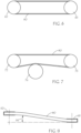
- FIG's 1-4 show four embodiments of the inventive V-belt.
- V-belt 10 includes tensile layer 12 which includes tensile cord 13 and very high-modulus compound 14 which will be referred to herein as the adhesion gum 14.
- V-belt 10 also includes overcord 16 and undercord 18.
- V-belt 20 includes tensile layer 12 which includes tensile cord 13 and adhesion gum 14.
- V-belt 10 also includes overcord 16 and undercord 18.
- V-belt 20 also includes a single set of notches 25 which are on the inside or bottom surface of the belt. The notches are alternating depressions or troughs and cogs or tooth-like projections. These alternating depressions and projections may preferably follow a generally sinusoidal path as illustrated which may serve to distribute and minimize bending stresses as the belt passes around pulleys or sheaves during its operation.
- V-belt 30 includes tensile layer 12 which includes tensile cord 13 and adhesion gum 14.
- V-belt 10 also includes overcord 16 and undercord 18.
- V-belt 30 also includes a single set of notches 37 which are on the outside or top surface of the belt.
- V-belt 40 includes tensile layer 12 which includes tensile cord 13 and adhesion gum 14.
- V-belt 10 also includes overcord 16 and undercord 18.
- V-belt 20 also includes two sets of notches 25 and 37 in the undercord and overcord, respectively.
- the tensile cord layer includes the tensile cord and the very-high-modulus, rubber compound, which is also referred to herein as the "adhesion gum.” It should be understood that adhesion to the tensile cord and the undercord and overcord is just one of the functions of the adhesion gum. This compound is also the key to high transverse stiffness.
- the high-modulus, tensile cord layer is restricted to a relatively thin layer centered in the belt body which helps the tensile layer remain sufficiently flexible in the longitudinal direction.
- the tensile cord layer thickness may be only slightly thicker than the cord diameter, up to several times the cord diameter.
- the tensile cord layer may range from about 1-mm to about 7-mm in thickness, or from 1.5-mm to 5-mm in thickness, or from 2 to 3-mm thick.
- the tensile cord layer thickness including both tensile cord and adhesion gum, could range from 1 to 7, or 1 to 5, or 1.5 to 5, or 2 to 3 cord diameters.
- the adhesive gum 14 is illustrated in exaggerated form in order to visually distinguish it from the other elastomeric portions of the belt.
- the cured composite is frequently visually indistinguishable from the surrounding elastomeric belt body portion except in certain cases, e.g., where one and not the other of the adhesive gum 14 and the undercord 18 and/or overcord 16 are fiber loaded.
- the adhesion gum furthermore need not form a perfectly flat interface at the overcord or undercord or resemble the proportions that might be suggested by the FIG's.
- the adhesion gum may include lobes, or other shapes of flow lines instead of the smooth interface represented in the figures.
- the tensile cord may be any desired high-modulus fiber material known for V-belts.
- the tensile cord could be polyester, nylon, fiberglass, carbon fiber, aramid (either para-, meta-, or co-poly-aramid), steel wire or cable, or combinations thereof. Polyester, nylon, and aramid are preferred cord materials.
- the tensile cord may be any desired construction, i.e., yarn style, twist levels, plied or cabled, etc.
- the tensile cord may be treated with any desired sizing, coating, adhesive and the like.
- the tension section, or overcord 16, of the belt body is radially outside of the tensile cord layer, i.e., the top layer of the belt when the belt is in the upright position.
- the compression section, or undercord 18, of the belt body is radially inward of the tensile cord layer, i.e., the bottom layer when the belt is in the upright orientation.
- the rubber compound in the tension section is referred to as the overcord.
- the rubber compound in the compression section is referred to as the undercord.
- the overcord is approximately the same thickness as the undercord, since the tensile cord layer is centrally located.
- the overcord and undercord may be of the same composition, so that whether an inverted belt or an upright belt is cut from the same sleeve, it will have the same composition and comparable properties.
- the under cord and overcord compounds are the same composition.
- the under cord and overcord compounds possess greater flexibility and crack resistance than the adhesion gum. Generally, greater flexibility requires lower modulus, higher elongation, and the like.
- the overcord and undercord compound may be selected to give a desired coefficient of friction ("COF") between the angled sides and a sheave. The COF of the overcord and undercord will dominate the frictional properties of the V-belt because of their higher surface area, relative to the adhesion gum in the tensile cord layer.
- COF coefficient of friction
- Short fibers may be included in the overcord and undercord compounds. Short fibers can help provide the desired COF. When oriented axially (i.e. transversely in the belt), the short fibers can help provide transverse stiffness while having a minimal impact on longitudinal flexibility.
- FIG. 5 illustrates a point in one possible manufacturing process for making the inventive CCL V-belts.
- a mandrel 50 may be provided on which to build up the belt materials.
- a cylindrical mandrel (with a smooth cylindrical surface) may be used to make the V-belts having one or both of the inner and outer surfaces smooth.
- a grooved or wavy mandrel may be used to build up and/or mold a notched embodiment. Alternately, a grooved or wavy matrix may be wrapped around a smooth mandrel to mold a notched embodiment.
- One of the undercord or overcord may be applied to the mandrel first. Then the materials of the tensile cord layer may be applied thereon.
- the tensile cord layer 12 may be applied in a number of ways.
- the tensile cord may be helically wound onto the mandrel.
- the tensile cord may include two cords, such as an "S" twisted cord and a "Z" twisted cord, applied simultaneously in parallel fashion.
- the adhesion gum 14 may be applied before the tensile cord or after the tensile cord or as two layers, one before and one after the tensile cord. Finally the other of the overcord and undercord is applied thereon.
- the resulting built-up material layers is called the belt slab or belt sleeve 52.
- the belt sleeve 52 may be cured on the mandrel 50 or moved to a second mandrel or mold for curing (or vulcanization). Curing may be accomplished in any way known in the art. A typical method is to place a cure bag around the belt sleeve on the mandrel and apply heat and pressure sufficient to cure the belt sleeve.
- the cure bag may be grooved or wavy if notches are desired. Alternately, a grooved or wavy matrix may be wrapped around the belt slab before placing in a smooth cure bag if notches are desired.
- the belt sleeve may be removed from the mandrel or mold, or processed further on the mandrel or mold.
- the most important further processing step is the cutting of the belt sleeve to form individual CCL V-belts.
- the preferred method is to alternate the cutting angle as shown in FIG. 5 , so that upright belts 54 are cut alternately with inverted belts 55.
- This cutting approach makes maximum use of the materials, resulting in only two partial belt end pieces 53 as waste from each belt sleeve.
- the cutting may be carried out on separate cutting devices to avoid damaging the mandrel or mold.
- process steps that may be carried out include applying labels or printing on the belt, touch grinding or machining one or more surfaces for a desired final effect or appearance, and flipping the belts that are made inverted to assume the upright orientation.
- the belts could be made the same by V-cutting the sleeve, or by square cutting followed by grinding the V-angles.
- all the belts can be made inverted or all upright, depending on the preferred manufacturing process. This would, of course mean the process does not achieve the reduced waste that is a prime reason for making CCL V-belts.
- the notches on both sides of the belt are substantially equivalent, but they do not mirror each other.
- the peaks and valleys of the top and bottom notches go in and out of phase with some periodicity.
- the periodicity or pitch may be dependent on belt circumference as one notch pattern bends inward and the other bends outward.
- the top to bottom notch orientation at any point of any belt is therefore usually random.
- the adhesion gum, overcord and undercord compounds are preferably rubber formulations with a base elastomer chosen from ethylene-alpha-olefin copolymers.
- Suitable ethylene-alpha-olefin copolymers include poly(ethylene propylene), poly(ethylene butene), poly(ethylene pentene), and so forth, up to and including poly(ethylene octene).
- Suitable copolymers include any of the aforementioned that may also include one or more additional monomers such as a cure site diene monomer or other unsaturated component.
- the most notable example is ethylene-propylene-diene terpolymer elastomer (EPDM).
- EPDM ethylene-propylene-diene terpolymer elastomer
- the rubber formulations for the adhesion gum, overcord and undercord compounds preferably include a metal salt of an ⁇ - ⁇ -unsaturated organic acid.
- the metal salts of ⁇ - ⁇ -unsaturated organic acids useful in the present invention are metal salts of acids such as, for example, acrylic, methacrylic, maleic, fumaric, ethacrylic, vinyl-acrylic, itaconic, methyl itaconic, aconitic, methyl aconitic, crotonic, alpha-methylcrotonic, ascorbic, cinnamic, and 2,4- dihydroxy cinnamic acids.
- These salts may be of zinc, cadmium, calcium, magnesium, sodium or aluminum, and are preferably those of zinc.
- the preferred metal salts of ⁇ - ⁇ -unsaturated organic acids are zinc diacrylate and zinc dimethacrylate.
- the most preferred metal salt of unsaturated organic acid is zinc dimethacrylate. Amounts of the metal salt useful in the present invention depend on which component of the belt is formulated.
- the rubber formulations for the adhesion gum, overcord and undercord compounds preferably include one or more reinforcing fillers.
- Preferred reinforcing fillers include silica and carbon black.
- the amount and type of filler depends on which component of the belt is formulated. In general, higher structure, smaller particle size fillers are more reinforcing and therefore preferred for obtaining the high modulus compounds useful in the invention.
- the adhesion gum is preferably a very-high-modulus compound. Modulus may be measured by any suitable direct measurement such as ASTM D412 or ISO 37. Modulus may also be indicated by indirect measurements such as Shore Durometer, preferably either the A or D scale, as taught for example in ASTM D2240, or using the IRHD scale, as taught for example in ASTM D1415. MH (i.e., highest torque attained) on a cure rheometer test (e.g. the moving die rheometer as described in ASTM D5289) is also a good indicator of the very high modulus of the adhesion gum at elevated temperature.
- the adhesion gum preferably includes no short fiber reinforcements.
- the preferred adhesion gum is thus fairly isotropic in its physical properties.
- the anisotropy of the adhesion gum defined for example as with-grain/cross-grain modulus, is less than 2.0, or less than 1.5, or less than 1.2.
- the amount of the metal salt of the ⁇ - ⁇ -unsaturated organic acid may range from about 20 phr to about 50 phr, and are preferably from about 25 to about 35 phr.
- Phr refers to the number of parts per hundred parts of the rubber or elastomer component or components.
- the reinforcing filler for the adhesion gum is preferably mostly silica, with optionally some carbon black as well. Silica is often found to produce higher modulus than carbon black at a similar loading.
- the total levels of reinforcing filler may be in the range of from about 30 phr to about 200 phr, preferably from about 40 phr to about 100 phr.
- Silane, titanate, or zirconate coupling agents may also be used with the reinforcing fillers to further enhance the modulus and other physical properties of the compounds.
- Very high modulus adhesion gums may be formulated using the relevant teachings thereof set forth in U.S. Pat. No. 5,610,217 and U.S. Pat. No. 6,616,558 with the exception of the teachings on use of short or discontinuous fibers.
- the preferred range for the modulus of the adhesion gum, based on the tensile stress at 10% elongation (“M10") determined in accordance with ASTM D412 at RT is greater than 500 psi (3.45 MPa).
- the preferred range for M10 of the adhesion gum at 125°C (257°F) is greater than 250 psi (1.72MPa), or greater than 350 psi (2.41MPa), or from 400 psi (2.76MPa) to about 600 psi (about 4.14MPa), in both the with-grain and cross-grain directions.
- the preferred modulus, indicated by the durometer hardness is greater than about 90 Shore A, or greater than about 40 Shore D, or from 40 to 60 Shore D.
- Preferred MH values are greater than 80 in-lb. (9 N-m), or greater than 90 in-lb. (10 N-m) or greater than 100 in-lb. (11 N-m), or greater than 110 in-lb. (12 N-m), or in the range from 80 to 140 in-lb. (9-16 N-m), or 90 to 130 in-lb. (10-15 N-m), or 100 to 120 in-lb. (11-14 Nm), or 110 to 130 in. lb. (12-15 N-m).
- the MH may be measured at a temperature of 177°C or higher, preferably at 198°C or 200°C.
- the overcord is preferably a lower modulus formulation than the adhesion gum.
- the overcord is preferably made anisotropic in properties by the addition of short fibers which are oriented by calendering, extrusion or other processing operation.
- the direction of orientation of the fibers is called the "with-grain” direction, and the direction orthogonal to the fibers is called the "cross-grain” direction.
- the overcord is preferably of a lower cross-grain modulus than the adhesion gum modulus, but it may be of a comparable or even greater modulus in the with-grain direction relative to the adhesion gum modulus due to the fiber.
- the overcord is suitably flexible in the belt longitudinal direction (which will be the cross-grain direction of the compound) to withstand repeated flexing at the higher strains experienced by that portion of the belt as it wraps around sheaves during use.
- the adhesion gum being restricted to the region of the tensile cord layer, does not experience such severe strains and stresses during belt use. Therefore the adhesion gum modulus can be made very high indeed.
- the undercord is also preferably a lower modulus formulation than the adhesion gum.
- the undercord is also preferably made anisotropic in properties by the addition of short fibers which are oriented by calendering, extrusion or other processing operation so that the with grain direction is aligned across the width of the belt.
- the undercord formulation may be the same as the overcord formulation. When the overcord and undercord are the same formulation and both oriented transverse to the cord direction in the belt, the individual belts cut from the same belt sleeve in inverted and upright orientations will have matching constructions (as illustrated in FIG. 5 ).
- the preferred range for the M10 of the overcord and undercord at room temperature (“RT") is greater than 100 psi (0.69 MPa), or greater than 200 psi (1.38 MPa), or greater than 300 psi (2.07 MPa), or greater than 400 psi (2.76 MPa), in the cross-grain direction and greater than 200 psi (1.38 MPa), greater than 400 psi (2.76 MPa), greater than 600 psi (4.14 MPa), or greater than 900 psi (6.21 MPa), in the with-grain direction.
- the anisotropy ratio based on M10 at RT for the overcord and undercord is preferably greater than 2.0, greater than 2.5, or about 3 or greater than 3.0.
- the preferred range for M10 of the overcord and undercord at 125°C is greater than 50 psi (0.35 MPa), greater than 100 psi (0.69 MPa), greater than 200 psi (1.38 MPa), or greater than 250 psi (1.72 MPa), or up to about 200 psi (about 1.38 MPa), 400 psi (2.76 MPa), or 600 psi (4.14 MPa), in the cross-grain direction and greater than 100 psi (0.69 MPa), greater than 200 psi (1.38 MPa), greater than 500 psi (3.45 MPa), or greater than 600 psi (4.14 MPa), in the with-grain direction.
- the anisotropy ratio based on M10 at 125°C for the overcord and undercord is preferably greater than 2.0, greater than 2.5, or about 3 or greater than 3.0.
- the preferred modulus for overcord and undercord, indicated by the durometer hardness at RT is greater than about 75, 80, 85, or 90 Shore A, or greater than about 30 or 40 Shore D, or from 40 to 60 Shore D.
- the preferred modulus for overcord and undercord, indicated by the durometer hardness is a few points less, or from 3 to 20 points less, or from 5 to 10 points less than that of the adhesion gum.
- Preferred MH values are less than 80 in-lb. (9 Nm), or less than 70 in-lb. (8 Nm) or less than 60 in-lb.
- the MH may be measured at a temperature of 177°C or higher, preferably at 198°C or 200°C.
- Short fibers useful in the overcord and undercord compounds may be of any conventional or suitable material or form, including for example materials such as cotton, kenaf, wood, rayon, polyester, aramid, carbon (including nanotubes), polyimide, polyvinyl alcohol, nylon and fiberglass; and in forms including staple or chopped fibers, and pulped or flocked fibers.
- the fibers may optionally be treated with sizing, an adhesive, or other conventional and/or suitable fiber treatments as are known in the art.
- Preferred fibers are cotton, nylon, polyester and aramids. Most preferred is cotton. The level needed should be readily discernable by the skilled practitioner in view of the levels of reinforcing fillers and other ingredients.
- the amount of fiber may range from about 1 phr to about 75 phr, or from about 10% up to about 20% by volume.
- Short fiber lengths may range up to about 7 mm.
- Some natural staple fibers may have longer lengths.
- Chopped synthetic fibers typically are useful in the range of 1 to 3 mm.
- undercord and overcord formulations may also utilize the relevant teachings set forth in U.S. Pat. No. 5,610,217 and U.S. Pat. No. 6,616,558 including the teachings on use of short or discontinuous fibers.
- the adhesion gum, overcord and undercord compounds may include: other elastomers blended at less than 50%, preferably less than 20%, of the total elastomer by weight; other reinforcing and non-reinforcing fillers; process aids and dispersion aids; anti-degradants; plasticizers, softeners, and oils; coagents; curatives; and the like, as long as the desired properties are obtained.
- any suitable cure system may be used for the adhesion gum, overcord and undercord, and they may all be similar for maximum compatibility and adhesion.
- the compound is cured with an organic peroxide or other free-radical promoting material, optionally in the presence of a minor amount of sulfur in a mixed cure system.
- Suitable peroxides for curing ethylene elastomers include for example, dicumyl peroxide, bis-(t-butyl peroxy-diisopropyl benzene, t-butyl perbenzoate, di-t-butyl peroxide, 2,5-dimethyl-2,5-di-t-butylperoxyhexane, ⁇ - ⁇ -bis(t-butylperoxy) diisopropylbenzene.
- the preferred organic peroxide curative is ⁇ - ⁇ -bis(t-butylperoxy) diisopropylbenzene.
- Cure-effective amounts of organic peroxide for purposes of the present invention are typically from about 2 to about 10 phr. Preferred levels of organic peroxide are from about 4 to about 6 phr. Sulfur may optionally be added to the organic peroxide curative as part of a mixed cure system in an amount of from about 0.01 to about 1.0 phr.
- Flexibility or flex resistance of the compounds may be measured in accordance with the DeMattia fatigue test as described in ASTM D430 Method B, or the pierced DeMattia crack growth test of ASTM D813. Flex life measured in Kilocycles ("kcycles") for an initial crack to grow to one inch (the width of the specimen) may be used as a relative indicator of compound performance under flex.
- the compounds may be mixed according to known methods. For example they may be mixed in an internal mixer, finished on a mill, and calendered to a desired width and thickness for orienting the fiber and for building V-belts on a mandrel. Typical cure temperatures and pressures may be used.
- TABLE 1 An example formulation for adhesive gum and for both the overcord and undercord is shown in TABLE 1, with amounts given in phr. Some properties of the compounds are listed in TABLE 2.
- Tb is the tensile stress at break and Eb is the elongation at break per ASTM D412, die-C, pulled at 6 in./min (150 mm/min).
- the DeMattia crack growth test was run on the overcord/undercord compound at 300 cpm, 0.5" (1.27 cm) stroke, at 125°C, w/g. The same test was repeated on the overcord compound minus the cotton fiber. The mean flex life with fiber was about 5 kcycles/in., and without fiber about 19 kcycles/in.
- Example (“Ex.”) CCL V-belts were made as described herein in connection with FIG. 5 .
- the belts were so-called “B-section” belts of 42-inch (107 cm) nominal length, outside circumference 45 inches (114 cm).
- the example belts were constructed with the afore-mentioned compounds and with polyester tensile cords (S twist, with approximately 0.050" (1.27 mm) diameter at 16.5 cords per inch).
- Ex. 1 was constructed without notches according to the embodiment of FIG. 1 .
- the total thickness of calendered adhesion gum making up the tensile cord layer was 0.024 inches (0.061 cm).
- the overall thickness of the Ex. 1 belts was 0.39 in. (9.9 mm).
- Ex. 2 was constructed like Ex. 1, but with the thickness of adhesion gum at 0.060 inches (0.152 cm).
- the overall thickness of the Ex. 2 belts was 0.36 in. (9.1 mm).
- Ex. 4 is an inventive CCL V-belt made with dual notches according to the embodiment of FIG. 4 .
- the overall thickness of the Ex. 4 belts was 0.43 in. (10.9 mm).
- Comparative Example (Comp. Ex.) belts were also made or obtained.
- Comp. Ex. 3 was a CCL V-belt like Ex. 1 and Ex. 2 but made entirely with the above mentioned overcord/undercord formulation, i.e., without the very high modulus adhesion gum.
- Comp. Ex. 5 was a CCL V-belt like Ex. 4 but made entirely with the above mentioned overcord/undercord formulation, i.e., without the very high modulus adhesion gum.
- Comp. Ex. 6 was a conventional commercial B42 fabric-wrapped V-belt sold under the trademark Hi-Power ® II by Gates Corporation. Comp. Ex. 6 was flat like FIG. 1 , i.e., with no notches. The polyester tensile cord in Comp. Ex. 6 is positioned in the top 1/3 of the belt body, so it is not a CCL belt.
- Comp. Ex. 7 was a raw edge laminated CCL V-belt sold under the trademark Carlisle ® Super II by The Timken Company.
- Comp. Ex. 7 was a B62 construction with outside circumference of 65 inches (165 cm). Therefore, the belt test results for Comp. Ex.
- Comp. Ex. 7 had to be adjusted to an equivalent length basis for comparison to the other examples, using the life-length 2.75 power-law relationship of SAE J637.
- Comp. Ex. 7 is advertised as being superior to wrapped V-belts.
- Comp. Ex. 6 and Comp. Ex. 7 represent state-of the-art commercial belts.
- the load test illustrated in FIG. 6 , was a two-point test, with belt 60 trained around 4.75-inch (12.1 cm) diameter driver 62 and driven 63 sheaves, run at room temperature, 1750 rpm, and at two different load conditions.
- the first load condition was run with 262 lb. (1170 N) total tension and a load of 10 hp (7.5 kW).
- the second load condition was run with 313 lb. (1390 N) total tension and a load of 12 hp (8.9 kW).
- the load tests are greatly accelerated by using a significantly higher hp and a significantly higher tension than would be recommended for the belt in actual practice. Also, a 10% increase in hp is expected to reduce the belt life in half, as a first approximation.
- the recommended maximum hp for Comp. Ex. 3 is about 3.8 hp (2.8 kW) at about 70 lb. (310 N) total tension.
- the flex test illustrated in FIG. 7 , was run on 4.75-inch (12.1 cm) diameter driver 72 and driven 73 sheaves, with a 5-inch (12.7 cm) diameter flat back side idler 74, at room temperature, at 3600 rpm, 50 lb. (220 N) total tension, and no load.
- the flex test is greatly accelerated by using a significantly smaller idler diameter than recommended for actual use of the belt.
- the minimum back side idler diameter recommended by ARPM standards for these belts is about 7.7 inches (about 19.6 cm).
- the stability test involves increasing a misalignment angle 84 until the belt 60 rolls over.
- the layout for the stability test is a two-point test, run at room temperature on 6.75-inch (17.1 cm) diameter pulleys 82 and 83, at room temperature, at 700 rpm and 260 lb. (1160 N) total tension.
- the pulley axes are parallel, but one pulley 82 is displaced along its axis until the belt 60 fails by turning over.
- the misalignment angle 84 at turnover indicates the stability of the belt.
- the inventive CCL-V-belts thus provide a number of advantages. By avoiding the usual fabric laminations or wraps, the manufacturing is made simpler and the material cost is reduced. By applying the high-modulus materials described herein, the performance can be unexpectedly equal to or even better than conventional laminated or wrapped V-belts. Thus, the reputation for poor quality for CCL V-belts is surprisingly overcome.
- Double Notch CCL V-belts have better performance than conventional banded (wrapped) V-belts.
- a belt requires a certain axial stiffness to be able to carry load.
- the tensile cord provides most of the tensile strength for application of torque to a pulley, but the cord requires a "bridge" across the V pulley to support it. If not fully supported, the edge cords will elongate much more than the cords in the center resulting in earlier belt failure. So for pure load carrying, very stiff elastomeric materials are required.
- a belt must also flex in its running (longitudinal) direction. As such, very stiff belts will be less efficient due to hysteretic loss, and they will fail sooner due to higher belt operating temperatures. So what is needed is a belt that has a high ratio of axial to longitudinal stiffness. And not only is the ratio important. There will also be a minimum required axial stiffness as well as a maximum allowable bending stiffness.
- One means of delivering axial stiffness (or transverse rigidity) and longitudinal flexibility is to apply elastomeric materials with anisotropic properties.
- short fiber reinforced elastomers can yield distinctly orthotropic materials moduli.
- this means has been relied on for the bulk of the axial stiffness.
- this means is applied in the overcord and undercord in a way that maintains good flexibility.
- a second means of gaining axial stiffness is also applied, namely the adhesion gum.
- the traditional function of these gums is to merely flow around and adhere to the tensile cords.
- the adhesion gum is an ultra-high modulus material in a narrow band around the cord line.
- this material provides a much greater share of the axial stiffness of the belt than in conventional belts, while at the same time, keeping the high stiffness material very near the neutral axis of the belt.
- the ultra-high modulus material will never experience high strains that might cause hysteretic losses, but it will still provide sufficient axial stiffness.
- the result is a better balance of flexible elastomeric materials in overcord and undercord areas of the belt farther from the neutral axis.
- the result is a belt with good load durability and flexibility.
- the result is a belt with good energy efficiency and low hysteretic losses or heat buildup.
- the use of the EE materials also can result in very high heat resistance (potentially up to 285°F or 140°C operating temperatures) compared to traditional elastomers like polychloroprene or styrene-butadiene rubber.
- the invention relates to: A belt that has sufficient axial stiffness (tensile cord support) to be able to efficiently carry load well while still having a low longitudinal bending stiffness.
- the thickness of this tensile cord layer is preferably between 1 mm and 5 mm (including the tensile cord and the adhesion gum).
- the thickness of this layer may also be specified in multiples of the cord diameter or specified as a percent of the overall belt thickness.
- the remainder of the belt may be composed of a more flexible material to minimize bending stiffness.
- the tensile cord is positioned at the centerline of the belt.
- the belt may be notched on one or both sides.
- V-belt construction described herein is useful in a wide variety of V-belt applications. It should be recognized that this construction can also be used as the base belt body for other types or styles of V-belts, such as a fabric-wrapped V-belt (banded V-belt).
- the inventive construction could also be used as the basis for power bands, i.e., multiple V-belts banded together. It could also be used for variable speed V-belts.
- the belt materials described herein could be applied to a high cord-line V-belt.
- the inventive belt construction results in higher efficiency or more efficient belt performance than other V-belt constructions.
- the layout was as shown in FIG. 6 , with pulleys 62 and 63 having an outside diameter of 5.75" and a pitch diameter for B-section belt of 5.40".
- the driver was run at 1770 RPM with no applied torque.
- the average load, average driver speed and average driver torque were measured.
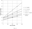
- the parasitic torque of the drive or bearing loss was determined by running a very thin, small belt at each hub load. Then the various example belts were run and the bearing loss subtracted to determine the power loss due to the belt construction at a given hub load. The power loss determined is reported in Table 4 in units of mW (milliwatts).
- the inventive CCL belt whether cut inverted or upright, runs with significantly less power loss than either of the conventional, comparative-example belts.
- the power loss is plotted versus the hub load in FIG. 9 , where it is clear that the data in Table 4 for each belt is well fit by a straight line.
- the lines for Ex. 2 fall well below the lines for the comparative examples.
- the inventive belts may be characterized by the design region described by the inequality: Power Loss (mW) ⁇ Hub Load (N)/60 (mW/N) + 15 (mW).
- the inventive V-belts have a center cord line so they can be cut from the slab they are made in without waste, half then are used inverted and half upright.
- the inventive belts have a very high-modulus adhesion gum layer at the cord line, and a lower modulus material both below and above the cordline.
- the inventive belts have no additional fabric or textile reinforcement layers. Yet the inventive belts can perform better on load-life tests and flex tests than wither conventional wrapped V-belts with higher cord lines or fabric reinforced CCL V-belts. Moreover, the inventive CCL V-belts can exhibit lower power loss than the conventional V-belts.
Landscapes
- Engineering & Computer Science (AREA)
- General Engineering & Computer Science (AREA)
- Mechanical Engineering (AREA)
- Textile Engineering (AREA)
- Compositions Of Macromolecular Compounds (AREA)
- Ropes Or Cables (AREA)
Claims (11)
- Courroie en V à ligne câblée centrale (10) qui n'a aucune couche de tissu de renfort et aucune enveloppe de tissu, la courroie en V à ligne câblée centrale (10) comprenant une ligne câblée centrée radialement (12) de câble de traction enroulé hélicoïdalement (13) incorporé dans une gomme adhésive à module très haut (14) ; une couche de sur-câble (16) ; et une couche de sous-câble (18) ;
dans laquelle la gomme adhésive (14) comprend un module sensiblement isotrope ; les couches de sur-câble et de sous-câble (16, 18) comprennent des modules inégaux dans le sens des grains et dans le sens transversal aux grains ; les modules dans le sens transversal aux grains de sur-câble et de sous-câble sont inférieurs au module de gomme adhésive. - Courroie en V à ligne câblée centrale (10) selon la revendication 1, dans laquelle le module de la gomme adhésive à module très haut (14), tel qu'indiqué par une valeur de MH sur un rhéomètre de durcissement à matrice oscillante à 177 °C ou plus, est supérieur à 80 pouce-livre ou 9,0 N-m.
- Courroie en V à ligne câblée centrale (10) selon la revendication 2, dans laquelle les modules du sur-câble (16) et du sous-câble (18), tels qu'indiqués par une valeur de MH sur un rhéomètre de durcissement à matrice oscillante à 177 °C ou plus, est inférieur à 80 pouce-livre ou 9,0 N-m.
- Courroie en V à ligne câblée centrale (10) selon la revendication 1, dans laquelle les modules anisotropes du sur-câble (16) et du sous-câble (18) sont le résultat de fibres courtes orientées et le module dans le sens des grains est orienté axialement dans la courroie.
- Courroie en V à ligne câblée centrale (10) selon la revendication 4, dans laquelle le module anisotrope du sur-câble (16) et du sous-câble (18) sont indiqués par un module dans le sens des grains sur sens transversal aux grains supérieur à 2,0.
- Courroie en V à ligne câblée centrale (10) selon la revendication 1, dans laquelle la gomme adhésive (14) n'a aucune fibre courte.
- Courroie en V à ligne câblée centrale (10) selon la revendication 1, dans laquelle le module sensiblement isotrope de la gomme adhésive (14) est indiqué par un module dans le sens des grains sur sens transversal aux grains inférieur à 2,0.
- Courroie en V à ligne câblée centrale (10) selon la revendication 1, dans laquelle la gomme adhésive (14), la couche de sur-câble (16) et la couche de sous-câble (18) sont sur la base d'un élastomère éthylène-alpha-oléfine, avec durcissement peroxyde, charge de renfort, et sel métallique d'un acide organique insaturé α-β.
- Courroie en V à ligne câblée centrale (10) selon la revendication 1, comprenant des encoches (25, 37) sur une ou les deux des surfaces radiales intérieure et extérieure.
- Courroie en V à ligne câblée centrale (10) selon la revendication 1, avec une quelconque combinaison des limitations des revendications 2 à 10.
- Courroie en V à ligne câblée centrale (10) selon la revendication 1, dans laquelle la perte de puissance mesurée en mW sur un dispositif d'essai à deux points et sans couple est dans la plage inférieure ou égale à la charge de moyeu en Newtons divisée par 60 plus 15 mW.
Applications Claiming Priority (2)
| Application Number | Priority Date | Filing Date | Title |
|---|---|---|---|
| US201962877763P | 2019-07-23 | 2019-07-23 | |
| PCT/US2020/043348 WO2021016495A1 (fr) | 2019-07-23 | 2020-07-23 | Courroie en v à ligne de câbles centrale |
Publications (2)
| Publication Number | Publication Date |
|---|---|
| EP4004400A1 EP4004400A1 (fr) | 2022-06-01 |
| EP4004400B1 true EP4004400B1 (fr) | 2023-07-12 |
Family
ID=72087145
Family Applications (1)
| Application Number | Title | Priority Date | Filing Date |
|---|---|---|---|
| EP20757015.1A Active EP4004400B1 (fr) | 2019-07-23 | 2020-07-23 | Courroie en v à ligne de câbles centrale |
Country Status (10)
| Country | Link |
|---|---|
| US (1) | US20220316555A1 (fr) |
| EP (1) | EP4004400B1 (fr) |
| JP (1) | JP7334330B2 (fr) |
| KR (1) | KR20220032624A (fr) |
| CN (1) | CN114286903B (fr) |
| BR (1) | BR112022001266A2 (fr) |
| CA (1) | CA3148251A1 (fr) |
| MX (1) | MX2022000906A (fr) |
| PL (1) | PL4004400T3 (fr) |
| WO (1) | WO2021016495A1 (fr) |
Family Cites Families (35)
| Publication number | Priority date | Publication date | Assignee | Title |
|---|---|---|---|---|
| US2016140A (en) | 1934-05-12 | 1935-10-01 | Dayton Rubber Mfg Co | Belt |
| US3090716A (en) * | 1958-09-12 | 1963-05-21 | Gates Rubber Co | Adhesive treatment and article of manufacture |
| GB1400799A (en) * | 1972-11-14 | 1975-07-23 | Goodyear Tire & Rubber | V-belts |
| US3941005A (en) * | 1975-03-03 | 1976-03-02 | The Gates Rubber Company | Power transmission belt |
| US3987684A (en) * | 1975-07-28 | 1976-10-26 | Dayco Corporation | Endless power transmission belt structure |
| US4106966A (en) | 1977-05-20 | 1978-08-15 | Dayco Corporation | Method of making toothed endless power transmission belts |
| JPS5582839A (en) * | 1978-12-16 | 1980-06-21 | Mitsuboshi Belting Ltd | Power transmitting v-belt and its manufacturing method |
| US4231826A (en) | 1978-12-22 | 1980-11-04 | The Gates Rubber Company | Process for forming V-belts and belt sleeves |
| US5610217A (en) | 1994-10-31 | 1997-03-11 | The Gates Corporation | Ethylene-alpha-olefin belting |
| EP1228325B2 (fr) * | 1999-11-12 | 2011-06-29 | The Gates Corporation | Courroie de transmission d'energie a textile en treillis dans le tissu corde externe ameliorant la penetration du caoutchouc |
| EP1235996B1 (fr) * | 1999-11-12 | 2007-01-10 | The Gates Corporation | Courroie de transmission de puissance comportant une gaine tubulaire tricotee |
| US6595883B1 (en) * | 2000-07-06 | 2003-07-22 | The Gates Corporation | V-belt for clutching drive applications |
| EP1309808B1 (fr) * | 2000-08-18 | 2005-08-03 | The Gates Corporation | Courroie de transmission d'energie comportant un element en caoutchouc adhesif a module eleve |
| US6695734B2 (en) * | 2000-12-21 | 2004-02-24 | The Goodyear Tire & Rubber Company | Power transmission belt |
| TW565661B (en) * | 2002-01-16 | 2003-12-11 | Gates Corp | Multi-ribbed belt with tip profile |
| US6824485B2 (en) * | 2002-07-09 | 2004-11-30 | The Gates Corporation | Power transmission belt |
| US20040033857A1 (en) * | 2002-08-13 | 2004-02-19 | Susan Welk | Belt |
| US7037578B2 (en) * | 2002-12-11 | 2006-05-02 | The Goodyear Tire & Rubber Company | Power transmission belt |
| US7201688B2 (en) * | 2004-03-09 | 2007-04-10 | The Gates Corporation | Power transmission belt |
| CN100473864C (zh) * | 2004-05-25 | 2009-04-01 | 坂东化学株式会社 | 传动皮带及其制造方法 |
| US7254934B2 (en) * | 2005-03-24 | 2007-08-14 | The Gates Corporation | Endless belt with improved load carrying cord |
| CN101160478A (zh) * | 2005-04-15 | 2008-04-09 | 邦多化学株式会社 | 摩擦传动带及其制造方法 |
| JP4834331B2 (ja) * | 2005-06-14 | 2011-12-14 | バンドー化学株式会社 | 摩擦伝動ベルト及びそれを用いたベルト伝動装置 |
| US7942773B2 (en) * | 2005-06-27 | 2011-05-17 | The Gates Corporation Ip Law Dept. | Banded power transmission V-belt |
| US9506527B2 (en) * | 2006-04-07 | 2016-11-29 | Gates Corporation | Power transmission belt |
| CN2908911Y (zh) * | 2006-04-07 | 2007-06-06 | 浙江三力士橡胶股份有限公司 | 农业机械用变速传动带 |
| US8197372B2 (en) * | 2006-04-07 | 2012-06-12 | The Gates Corporation | Power transmission belt |
| DE102008037561B4 (de) * | 2008-11-18 | 2020-06-18 | Contitech Antriebssysteme Gmbh | Artikel, insbesondere Antriebsriemen, mit einer Textilauflage und Verfahren zur Herstellung eines Antriebsriemens |
| US8206251B2 (en) * | 2009-04-30 | 2012-06-26 | The Gates Corporation | Double cogged V-belt for variable speed drive |
| US8809441B2 (en) * | 2009-08-03 | 2014-08-19 | The Gates Corporation | Method of reinforcing rubber and rubber composition |
| WO2011038200A1 (fr) * | 2009-09-24 | 2011-03-31 | The Gates Corporation | Courroie pour transmission à variation continue (cvt) |
| US9353466B2 (en) * | 2012-09-12 | 2016-05-31 | Timken Smo Llc | Hybrid power transmission cord |
| US9341232B2 (en) * | 2013-11-08 | 2016-05-17 | Gates Corporation | Two-component cord and method for molded power transmission belts |
| RU2670505C1 (ru) | 2015-05-11 | 2018-10-23 | Гейтс Корпорейшн | Ремень вариатора |
| US20170023098A1 (en) * | 2015-07-21 | 2017-01-26 | Gates Corporation | Power transmission belt |
-
2020
- 2020-07-23 PL PL20757015.1T patent/PL4004400T3/pl unknown
- 2020-07-23 CN CN202080059535.XA patent/CN114286903B/zh active Active
- 2020-07-23 JP JP2022504117A patent/JP7334330B2/ja active Active
- 2020-07-23 BR BR112022001266A patent/BR112022001266A2/pt unknown
- 2020-07-23 MX MX2022000906A patent/MX2022000906A/es unknown
- 2020-07-23 CA CA3148251A patent/CA3148251A1/fr active Pending
- 2020-07-23 EP EP20757015.1A patent/EP4004400B1/fr active Active
- 2020-07-23 KR KR1020227005297A patent/KR20220032624A/ko not_active Application Discontinuation
- 2020-07-23 WO PCT/US2020/043348 patent/WO2021016495A1/fr unknown
- 2020-07-23 US US17/628,154 patent/US20220316555A1/en active Pending
Also Published As
| Publication number | Publication date |
|---|---|
| CN114286903B (zh) | 2023-11-24 |
| JP2022542864A (ja) | 2022-10-07 |
| MX2022000906A (es) | 2022-02-16 |
| EP4004400A1 (fr) | 2022-06-01 |
| CN114286903A (zh) | 2022-04-05 |
| KR20220032624A (ko) | 2022-03-15 |
| CA3148251A1 (fr) | 2021-01-28 |
| PL4004400T3 (pl) | 2024-01-03 |
| JP7334330B2 (ja) | 2023-08-28 |
| WO2021016495A1 (fr) | 2021-01-28 |
| US20220316555A1 (en) | 2022-10-06 |
| BR112022001266A2 (pt) | 2022-06-14 |
Similar Documents
| Publication | Publication Date | Title |
|---|---|---|
| CN1821614B (zh) | 动力传送带和形成动力传送带的方法 | |
| KR102165523B1 (ko) | V 벨트 및 그 제조방법 | |
| KR101384731B1 (ko) | 가황 고무 벨트 | |
| EP2425151B1 (fr) | Courroie en v dentée double pour entraînement à vitesse variable | |
| EP2167840B1 (fr) | Courroie de transmission | |
| KR101598509B1 (ko) | 마찰전동벨트 | |
| JPH0243060B2 (fr) | ||
| WO2005116482A1 (fr) | Courroie de transmission et processus de production | |
| US20040214674A1 (en) | Frictional forced power transmission belt and belt drive system with the same | |
| WO2006001408A1 (fr) | Courroie de transmission de puissance | |
| JP2023058730A (ja) | 高効率ベルトおよびその製造方法 | |
| EP4004400B1 (fr) | Courroie en v à ligne de câbles centrale | |
| JP6577157B1 (ja) | ラップド結合vベルト | |
| JP4820107B2 (ja) | 伝動ベルト | |
| JP6007045B2 (ja) | 伝動用vベルト | |
| JP2017106617A (ja) | 摩擦伝動ベルト及びその製造方法 | |
| JP6567210B1 (ja) | ラップドvベルト | |
| JP7368082B2 (ja) | 伝動用vベルト | |
| JP4667956B2 (ja) | 伝動ベルトとその製造方法 | |
| TWI811040B (zh) | 齒型皮帶及其製造方法 | |
| JP6764047B1 (ja) | ラップドvベルト | |
| JP6782384B1 (ja) | ラップドvベルト伝動装置 | |
| JP2023021013A (ja) | 結合六角ベルトおよびその製造方法 | |
| WO2023147464A1 (fr) | Courroie à nervures en v | |
| JP5416601B2 (ja) | 摩擦伝動ベルト |
Legal Events
| Date | Code | Title | Description |
|---|---|---|---|
| STAA | Information on the status of an ep patent application or granted ep patent |
Free format text: STATUS: UNKNOWN |
|
| STAA | Information on the status of an ep patent application or granted ep patent |
Free format text: STATUS: THE INTERNATIONAL PUBLICATION HAS BEEN MADE |
|
| PUAI | Public reference made under article 153(3) epc to a published international application that has entered the european phase |
Free format text: ORIGINAL CODE: 0009012 |
|
| STAA | Information on the status of an ep patent application or granted ep patent |
Free format text: STATUS: REQUEST FOR EXAMINATION WAS MADE |
|
| 17P | Request for examination filed |
Effective date: 20220127 |
|
| AK | Designated contracting states |
Kind code of ref document: A1 Designated state(s): AL AT BE BG CH CY CZ DE DK EE ES FI FR GB GR HR HU IE IS IT LI LT LU LV MC MK MT NL NO PL PT RO RS SE SI SK SM TR |
|
| DAV | Request for validation of the european patent (deleted) | ||
| DAX | Request for extension of the european patent (deleted) | ||
| GRAP | Despatch of communication of intention to grant a patent |
Free format text: ORIGINAL CODE: EPIDOSNIGR1 |
|
| STAA | Information on the status of an ep patent application or granted ep patent |
Free format text: STATUS: GRANT OF PATENT IS INTENDED |
|
| INTG | Intention to grant announced |
Effective date: 20230120 |
|
| GRAS | Grant fee paid |
Free format text: ORIGINAL CODE: EPIDOSNIGR3 |
|
| GRAA | (expected) grant |
Free format text: ORIGINAL CODE: 0009210 |
|
| STAA | Information on the status of an ep patent application or granted ep patent |
Free format text: STATUS: THE PATENT HAS BEEN GRANTED |
|
| AK | Designated contracting states |
Kind code of ref document: B1 Designated state(s): AL AT BE BG CH CY CZ DE DK EE ES FI FR GB GR HR HU IE IS IT LI LT LU LV MC MK MT NL NO PL PT RO RS SE SI SK SM TR |
|
| REG | Reference to a national code |
Ref country code: CH Ref legal event code: EP |
|
| REG | Reference to a national code |
Ref country code: DE Ref legal event code: R096 Ref document number: 602020013783 Country of ref document: DE |
|
| REG | Reference to a national code |
Ref country code: IE Ref legal event code: FG4D |
|
| REG | Reference to a national code |
Ref country code: LT Ref legal event code: MG9D |
|
| REG | Reference to a national code |
Ref country code: NL Ref legal event code: MP Effective date: 20230712 |
|
| PGFP | Annual fee paid to national office [announced via postgrant information from national office to epo] |
Ref country code: FR Payment date: 20230821 Year of fee payment: 4 Ref country code: DE Payment date: 20230720 Year of fee payment: 4 |
|
| REG | Reference to a national code |
Ref country code: AT Ref legal event code: MK05 Ref document number: 1587493 Country of ref document: AT Kind code of ref document: T Effective date: 20230712 |
|
| PG25 | Lapsed in a contracting state [announced via postgrant information from national office to epo] |
Ref country code: NL Free format text: LAPSE BECAUSE OF FAILURE TO SUBMIT A TRANSLATION OF THE DESCRIPTION OR TO PAY THE FEE WITHIN THE PRESCRIBED TIME-LIMIT Effective date: 20230712 |
|
| PG25 | Lapsed in a contracting state [announced via postgrant information from national office to epo] |
Ref country code: GR Free format text: LAPSE BECAUSE OF FAILURE TO SUBMIT A TRANSLATION OF THE DESCRIPTION OR TO PAY THE FEE WITHIN THE PRESCRIBED TIME-LIMIT Effective date: 20231013 |
|
| PG25 | Lapsed in a contracting state [announced via postgrant information from national office to epo] |
Ref country code: ES Free format text: LAPSE BECAUSE OF FAILURE TO SUBMIT A TRANSLATION OF THE DESCRIPTION OR TO PAY THE FEE WITHIN THE PRESCRIBED TIME-LIMIT Effective date: 20230712 |
|
| PG25 | Lapsed in a contracting state [announced via postgrant information from national office to epo] |
Ref country code: IS Free format text: LAPSE BECAUSE OF FAILURE TO SUBMIT A TRANSLATION OF THE DESCRIPTION OR TO PAY THE FEE WITHIN THE PRESCRIBED TIME-LIMIT Effective date: 20231112 |
|
| PG25 | Lapsed in a contracting state [announced via postgrant information from national office to epo] |
Ref country code: SE Free format text: LAPSE BECAUSE OF FAILURE TO SUBMIT A TRANSLATION OF THE DESCRIPTION OR TO PAY THE FEE WITHIN THE PRESCRIBED TIME-LIMIT Effective date: 20230712 Ref country code: RS Free format text: LAPSE BECAUSE OF FAILURE TO SUBMIT A TRANSLATION OF THE DESCRIPTION OR TO PAY THE FEE WITHIN THE PRESCRIBED TIME-LIMIT Effective date: 20230712 Ref country code: PT Free format text: LAPSE BECAUSE OF FAILURE TO SUBMIT A TRANSLATION OF THE DESCRIPTION OR TO PAY THE FEE WITHIN THE PRESCRIBED TIME-LIMIT Effective date: 20231113 Ref country code: NO Free format text: LAPSE BECAUSE OF FAILURE TO SUBMIT A TRANSLATION OF THE DESCRIPTION OR TO PAY THE FEE WITHIN THE PRESCRIBED TIME-LIMIT Effective date: 20231012 Ref country code: LV Free format text: LAPSE BECAUSE OF FAILURE TO SUBMIT A TRANSLATION OF THE DESCRIPTION OR TO PAY THE FEE WITHIN THE PRESCRIBED TIME-LIMIT Effective date: 20230712 Ref country code: LT Free format text: LAPSE BECAUSE OF FAILURE TO SUBMIT A TRANSLATION OF THE DESCRIPTION OR TO PAY THE FEE WITHIN THE PRESCRIBED TIME-LIMIT Effective date: 20230712 Ref country code: IS Free format text: LAPSE BECAUSE OF FAILURE TO SUBMIT A TRANSLATION OF THE DESCRIPTION OR TO PAY THE FEE WITHIN THE PRESCRIBED TIME-LIMIT Effective date: 20231112 Ref country code: HR Free format text: LAPSE BECAUSE OF FAILURE TO SUBMIT A TRANSLATION OF THE DESCRIPTION OR TO PAY THE FEE WITHIN THE PRESCRIBED TIME-LIMIT Effective date: 20230712 Ref country code: GR Free format text: LAPSE BECAUSE OF FAILURE TO SUBMIT A TRANSLATION OF THE DESCRIPTION OR TO PAY THE FEE WITHIN THE PRESCRIBED TIME-LIMIT Effective date: 20231013 Ref country code: FI Free format text: LAPSE BECAUSE OF FAILURE TO SUBMIT A TRANSLATION OF THE DESCRIPTION OR TO PAY THE FEE WITHIN THE PRESCRIBED TIME-LIMIT Effective date: 20230712 Ref country code: ES Free format text: LAPSE BECAUSE OF FAILURE TO SUBMIT A TRANSLATION OF THE DESCRIPTION OR TO PAY THE FEE WITHIN THE PRESCRIBED TIME-LIMIT Effective date: 20230712 Ref country code: AT Free format text: LAPSE BECAUSE OF FAILURE TO SUBMIT A TRANSLATION OF THE DESCRIPTION OR TO PAY THE FEE WITHIN THE PRESCRIBED TIME-LIMIT Effective date: 20230712 |
|
| PGFP | Annual fee paid to national office [announced via postgrant information from national office to epo] |
Ref country code: PL Payment date: 20230822 Year of fee payment: 4 |
|
| REG | Reference to a national code |
Ref country code: CH Ref legal event code: PL |
|
| REG | Reference to a national code |
Ref country code: BE Ref legal event code: MM Effective date: 20230731 |
|
| PG25 | Lapsed in a contracting state [announced via postgrant information from national office to epo] |
Ref country code: LU Free format text: LAPSE BECAUSE OF NON-PAYMENT OF DUE FEES Effective date: 20230723 |
|
| PG25 | Lapsed in a contracting state [announced via postgrant information from national office to epo] |
Ref country code: LU Free format text: LAPSE BECAUSE OF NON-PAYMENT OF DUE FEES Effective date: 20230723 |
|
| REG | Reference to a national code |
Ref country code: IE Ref legal event code: MM4A |
|
| PG25 | Lapsed in a contracting state [announced via postgrant information from national office to epo] |
Ref country code: SM Free format text: LAPSE BECAUSE OF FAILURE TO SUBMIT A TRANSLATION OF THE DESCRIPTION OR TO PAY THE FEE WITHIN THE PRESCRIBED TIME-LIMIT Effective date: 20230712 Ref country code: RO Free format text: LAPSE BECAUSE OF FAILURE TO SUBMIT A TRANSLATION OF THE DESCRIPTION OR TO PAY THE FEE WITHIN THE PRESCRIBED TIME-LIMIT Effective date: 20230712 Ref country code: EE Free format text: LAPSE BECAUSE OF FAILURE TO SUBMIT A TRANSLATION OF THE DESCRIPTION OR TO PAY THE FEE WITHIN THE PRESCRIBED TIME-LIMIT Effective date: 20230712 Ref country code: DK Free format text: LAPSE BECAUSE OF FAILURE TO SUBMIT A TRANSLATION OF THE DESCRIPTION OR TO PAY THE FEE WITHIN THE PRESCRIBED TIME-LIMIT Effective date: 20230712 Ref country code: CZ Free format text: LAPSE BECAUSE OF FAILURE TO SUBMIT A TRANSLATION OF THE DESCRIPTION OR TO PAY THE FEE WITHIN THE PRESCRIBED TIME-LIMIT Effective date: 20230712 Ref country code: SK Free format text: LAPSE BECAUSE OF FAILURE TO SUBMIT A TRANSLATION OF THE DESCRIPTION OR TO PAY THE FEE WITHIN THE PRESCRIBED TIME-LIMIT Effective date: 20230712 Ref country code: MC Free format text: LAPSE BECAUSE OF FAILURE TO SUBMIT A TRANSLATION OF THE DESCRIPTION OR TO PAY THE FEE WITHIN THE PRESCRIBED TIME-LIMIT Effective date: 20230712 Ref country code: CH Free format text: LAPSE BECAUSE OF NON-PAYMENT OF DUE FEES Effective date: 20230731 |
|
| PLBE | No opposition filed within time limit |
Free format text: ORIGINAL CODE: 0009261 |
|
| STAA | Information on the status of an ep patent application or granted ep patent |
Free format text: STATUS: NO OPPOSITION FILED WITHIN TIME LIMIT |