EP4002684B1 - Fotovoltaikstruktur zum bedecken von mindestens einem teil mindestens einer gebäudefassade - Google Patents
Fotovoltaikstruktur zum bedecken von mindestens einem teil mindestens einer gebäudefassade Download PDFInfo
- Publication number
- EP4002684B1 EP4002684B1 EP21208388.5A EP21208388A EP4002684B1 EP 4002684 B1 EP4002684 B1 EP 4002684B1 EP 21208388 A EP21208388 A EP 21208388A EP 4002684 B1 EP4002684 B1 EP 4002684B1
- Authority
- EP
- European Patent Office
- Prior art keywords
- mast
- photovoltaic
- modules
- facade
- photovoltaic modules
- Prior art date
- Legal status (The legal status is an assumption and is not a legal conclusion. Google has not performed a legal analysis and makes no representation as to the accuracy of the status listed.)
- Active
Links
- 230000001939 inductive effect Effects 0.000 claims description 7
- 238000009413 insulation Methods 0.000 claims description 7
- 238000005253 cladding Methods 0.000 claims description 6
- 238000000034 method Methods 0.000 claims description 6
- 230000000694 effects Effects 0.000 claims description 2
- 238000000429 assembly Methods 0.000 description 14
- 238000009434 installation Methods 0.000 description 10
- 238000004519 manufacturing process Methods 0.000 description 10
- 238000010276 construction Methods 0.000 description 4
- 230000005611 electricity Effects 0.000 description 4
- 239000000463 material Substances 0.000 description 3
- 241001080024 Telles Species 0.000 description 2
- 230000009471 action Effects 0.000 description 2
- 239000011449 brick Substances 0.000 description 2
- 238000009422 external insulation Methods 0.000 description 2
- 230000010354 integration Effects 0.000 description 2
- 238000010008 shearing Methods 0.000 description 2
- OKTJSMMVPCPJKN-UHFFFAOYSA-N Carbon Chemical compound [C] OKTJSMMVPCPJKN-UHFFFAOYSA-N 0.000 description 1
- 230000000712 assembly Effects 0.000 description 1
- 230000008901 benefit Effects 0.000 description 1
- 230000002457 bidirectional effect Effects 0.000 description 1
- 229910052799 carbon Inorganic materials 0.000 description 1
- 239000011248 coating agent Substances 0.000 description 1
- 238000000576 coating method Methods 0.000 description 1
- 238000001816 cooling Methods 0.000 description 1
- 238000005260 corrosion Methods 0.000 description 1
- 230000007797 corrosion Effects 0.000 description 1
- 238000005034 decoration Methods 0.000 description 1
- 238000009826 distribution Methods 0.000 description 1
- 238000004146 energy storage Methods 0.000 description 1
- 238000001125 extrusion Methods 0.000 description 1
- 230000003100 immobilizing effect Effects 0.000 description 1
- 230000006698 induction Effects 0.000 description 1
- 239000011810 insulating material Substances 0.000 description 1
- 239000012774 insulation material Substances 0.000 description 1
- 230000004048 modification Effects 0.000 description 1
- 238000012986 modification Methods 0.000 description 1
- 239000003973 paint Substances 0.000 description 1
- 230000008569 process Effects 0.000 description 1
- 230000005855 radiation Effects 0.000 description 1
- 239000007787 solid Substances 0.000 description 1
- 230000003068 static effect Effects 0.000 description 1
- 238000009423 ventilation Methods 0.000 description 1
Images


Classifications
-
- H—ELECTRICITY
- H02—GENERATION; CONVERSION OR DISTRIBUTION OF ELECTRIC POWER
- H02S—GENERATION OF ELECTRIC POWER BY CONVERSION OF INFRARED RADIATION, VISIBLE LIGHT OR ULTRAVIOLET LIGHT, e.g. USING PHOTOVOLTAIC [PV] MODULES
- H02S20/00—Supporting structures for PV modules
- H02S20/20—Supporting structures directly fixed to an immovable object
- H02S20/22—Supporting structures directly fixed to an immovable object specially adapted for buildings
- H02S20/26—Building materials integrated with PV modules, e.g. façade elements
-
- Y—GENERAL TAGGING OF NEW TECHNOLOGICAL DEVELOPMENTS; GENERAL TAGGING OF CROSS-SECTIONAL TECHNOLOGIES SPANNING OVER SEVERAL SECTIONS OF THE IPC; TECHNICAL SUBJECTS COVERED BY FORMER USPC CROSS-REFERENCE ART COLLECTIONS [XRACs] AND DIGESTS
- Y02—TECHNOLOGIES OR APPLICATIONS FOR MITIGATION OR ADAPTATION AGAINST CLIMATE CHANGE
- Y02B—CLIMATE CHANGE MITIGATION TECHNOLOGIES RELATED TO BUILDINGS, e.g. HOUSING, HOUSE APPLIANCES OR RELATED END-USER APPLICATIONS
- Y02B10/00—Integration of renewable energy sources in buildings
- Y02B10/10—Photovoltaic [PV]
-
- Y—GENERAL TAGGING OF NEW TECHNOLOGICAL DEVELOPMENTS; GENERAL TAGGING OF CROSS-SECTIONAL TECHNOLOGIES SPANNING OVER SEVERAL SECTIONS OF THE IPC; TECHNICAL SUBJECTS COVERED BY FORMER USPC CROSS-REFERENCE ART COLLECTIONS [XRACs] AND DIGESTS
- Y02—TECHNOLOGIES OR APPLICATIONS FOR MITIGATION OR ADAPTATION AGAINST CLIMATE CHANGE
- Y02B—CLIMATE CHANGE MITIGATION TECHNOLOGIES RELATED TO BUILDINGS, e.g. HOUSING, HOUSE APPLIANCES OR RELATED END-USER APPLICATIONS
- Y02B10/00—Integration of renewable energy sources in buildings
- Y02B10/20—Solar thermal
-
- Y—GENERAL TAGGING OF NEW TECHNOLOGICAL DEVELOPMENTS; GENERAL TAGGING OF CROSS-SECTIONAL TECHNOLOGIES SPANNING OVER SEVERAL SECTIONS OF THE IPC; TECHNICAL SUBJECTS COVERED BY FORMER USPC CROSS-REFERENCE ART COLLECTIONS [XRACs] AND DIGESTS
- Y02—TECHNOLOGIES OR APPLICATIONS FOR MITIGATION OR ADAPTATION AGAINST CLIMATE CHANGE
- Y02E—REDUCTION OF GREENHOUSE GAS [GHG] EMISSIONS, RELATED TO ENERGY GENERATION, TRANSMISSION OR DISTRIBUTION
- Y02E10/00—Energy generation through renewable energy sources
- Y02E10/50—Photovoltaic [PV] energy
Definitions
- the present invention relates to a photovoltaic structure intended to be mounted along at least part of at least one facade of a building, in particular of a detached house.
- Photovoltaic modules for generating electricity are usually mounted on the roofs of buildings.
- the facades of the buildings offer large surfaces available to receive these modules.
- the photovoltaic modules can be fixed directly to the facade, or via an intermediate structure fixed to the facade.
- the thermal insulation is generally done from the outside, ie a thermal insulating material generally in the form of a plate is fixed for example on the concrete or brick wall. It is not possible to fix the modules or a support structure in the thermal insulation material which is not sufficiently resistant from a mechanical point of view.
- the document CN 103806580 describes a supporting structure of photovoltaic modules which is fixed to the concrete or brick wall by means of screws which cross all the thickness of the thermal insulation.
- the thermal insulation has a significant thickness, several centimeters, for example 10 cm, which implies the implementation of long screws, the structure is then cantilevered and the screws then undergo a significant shearing force. .
- the document KR 20200006161 A describes photovoltaic modules according to the prior art.
- a photovoltaic structure intended to cover at least part of at least one facade of a building of simplified assembly
- a photovoltaic structure comprising at least one mast intended to be oriented vertically along the facade, at least one photovoltaic module fixed to the mast, the mast comprising fixing means at its longitudinal ends so fixing the mast along at least one facade of a building.
- the structure according to the invention is self-supporting thanks to the implementation of at least one mast and does not require fixing through the thermal insulation.
- the lower longitudinal end of the mast is fixed in the foundation sole of the building and the upper longitudinal end of the mast is fixed to the overhang of the roof of the building.
- the structure is particularly advantageous for mounting along the corners of a building in which fixing to the wall becomes very complex.
- the structure comprises for example three masts, a first mast running along the junction between the two facades, a second mast running along one of the facades and the third mast running along the other facade and modules being mounted between or on the first mast and the second mast and the first mast and the third mast.
- the electrical connection means of the photovoltaic modules are partly or completely carried by the mast or masts.
- One of the subjects of the present application is a photovoltaic structure intended to cover at least part of a facade of a building, comprising at least one mast having a longitudinal axis intended to be oriented vertically and photovoltaic modules fixed to the mast, said mast being self-supporting and comprising a first lower longitudinal end configured to be fixed to the ground and a second upper longitudinal end configured to be attached to an upper part of the building.
- the photovoltaic structure comprises means for electrical connection of the photovoltaic modules to an external installation integrated into the at least one mast.
- the photovoltaic structure comprises first photovoltaic modules on one side of the longitudinal axis of the mast, and second photovoltaic modules on the other side of the longitudinal axis of the mast, the first and second photovoltaic modules being oriented relative to each other so as to form an angle between them and so that, when the mast is mounted along a corner of the building, the first photovoltaic modules cover part of a first facade and the second photovoltaic modules cover a part of a second facade, the first and the second facades meeting at said angle.
- photovoltaic modules are rotatably mounted on the mast around the longitudinal axis of the mast so as to be able to modify their angular orientation around the mast.
- the photovoltaic structure can comprise motorized means configured to modify the orientation of the photovoltaic modules.
- the at least one mast and the photovoltaic modules are configured so that the photovoltaic modules are capable of sliding vertically along the mast until reaching the desired location.
- the structure may comprise at least one longitudinal groove formed in the mast, at least one carriage mounted to slide in the groove, a photovoltaic module being fixed to the carriage, and module locking means along the mast.
- the locking means comprise at least one finger carried by the carriage, said finger movable in a direction transverse to the longitudinal axis of the mast and elastically biased outwards, and windows in the mast at the different locations of the modules photovoltaic along the mast, said finger being configured to cooperate with said window is to lock the module at the location of said window.
- the locking means are unidirectional, the locking means allowing movement in one direction of the carriage under the effect of a force in said direction of movement along the longitudinal direction of the mast.
- the photovoltaic structure can comprise at least one other mast so that the photovoltaic modules are held by two opposite parallel edges.
- the photovoltaic structure comprises a converter for each photovoltaic module.
- the converter can be a contactless converter with inductive transfer, comprising a primary on a rear face of the photovoltaic module and a secondary on the mast and, when the photovoltaic module is mounted on the mast, the primary can be automatically facing the secondary.
- the photovoltaic structure can comprise a module having an additional function with respect to the photovoltaic modules or a function different from that of the photovoltaic modules.
- the photovoltaic modules are capable of converting light energy on their two faces.
- Another object of the present application is a building comprising several facades, at least one photovoltaic structure according to the invention covering at least a part of at least one facade of said building, the at least one mast being fixed to the ground and to a part top of the building.
- the building can have a photovoltaic structure at each corner.
- the building comprises a layer of thermal insulation forming an exterior facade, the first longitudinal end of the at least one mast is fixed in a foundation sole, and the second longitudinal end of the at least one mast is fixed to an overhang of the roof.
- the at least one structure can be placed relative to a facade so that a clearance exists between a rear face of the photovoltaic modules and the facade of the building, for example of the order of one centimeter to a few centimeters.
- the mast can comprise several sub-assemblies, a first sub-assembly being fixed to the ground and the other sub-assemblies being stacked on the first sub-assembly, and the photovoltaic modules can be fixed on the sub-assemblies before or after their stacking .
- the mast is a single piece and the photovoltaic modules are fixed along the mast after fixing the mast along the facade.
- the covering method may comprise a step of electrical connection of the photovoltaic modules with a view to connection to an external installation, said step taking place simultaneously with the mechanical assembly of the structure.
- the at least one mast can be arranged along an angle between two facades.
- At least one module is mounted in the mast at the level of a lower part of the mast and is pushed upwards until it reaches its final location.
- a photovoltaic module will be referred to as a “module” for simplicity.
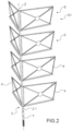
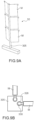
- a photovoltaic structure S1 making it possible to cover at least part of the facades of a building, in particular the facades of an individual dwelling house.
- the structure S1 comprises several sub-assemblies E intended to be arranged one above the other so as to form the complete structure represented in exploded view on the figure 2 .
- a sub-assembly E comprises an upright 2 with an axis Z, and two support frames 4 on either side of the upright 2.
- One of the vertical uprights of each frame is formed by the upright 2.
- the Z axis is intended to be oriented vertically.
- Each carrier frame advantageously comprises a stiffening structure 6 formed by two elements mounted crosswise and connecting the vertices of the frame together.
- the frames 4 are articulated in rotation on the upright 2 around the axis Z, for example hinges are provided between an edge of each frame 4 and the upright 2.
- the upright 2 is advantageously hollow, preferably it is formed by a tube, which allows the passage of the electrical connection means of the modules.
- the electrical connection between the electrical connection means of each upright is automatic during assembly of the sub-assemblies.
- the electrical connection means can be made using dedicated sealed connectors or a so-called “contactless” connection system by induction.
- the tube is of circular section, as a variant it can have a polygonal section, such as square.
- the P modules represented on the figures 3A to 3C in transparency are fixed by their rear face on the carrier frame.
- the longitudinal ends of the vertical upright 2 are advantageously configured to cooperate with the longitudinal ends of the uprights of the other sub-assemblies, so as to form a self-supporting mast 5 over the height of the facade.
- self-supporting mast means a mast which deforms little or not at all under its own weight and under the weight of the photovoltaic panel(s), and without the need for mechanical support along it.
- the lower longitudinal end 2.1 of an upright 2 forms a male part intended to penetrate into an upper longitudinal end forming a female part, of the mast of the module located directly below.
- the lower longitudinal end of the upright of the sub-assembly located at the bottom of the structure cooperates with fixing means 7 in the ground, for example in the foundation of the building, for example it is a foundation screw.
- the upper end of the upright of the sub-assembly located at the top of the structure is intended to cooperate with means of attachment to the upper part of the building, for example the roof overhang or a high point of the facade.
- anchor points at the corners of the frames located opposite the vertical upright 2. These anchor points are offset from the corner of the building which is an area on which fixing due to the external insulation can be complex.
- the mast can be fixed directly in the facade via for example two brackets at 90° arranged on the corner of the building.
- the same principle of facade fixing can be implemented by adapting the anchor points to the facade.
- the stiffening structure serves as a support for a converter, for example of the micro-inverter type 8 of the module which will be described later.
- the connection between the microinverter and the module can be wired or contactless type with inductive transfer.
- a module M is attached to each frame and is electrically connected to its micro-inverter.
- the foundation screw is fixed in the foundation opposite the edge connecting two facades.
- the mast is arranged at a distance from the facade allowing the mast to work mechanically, for example due to vibrations due to the wind, thermal expansion, without coming into contact with the facade.
- the distance between the mast and the facade is advantageously of the order of 10 mm.
- the first sub-assembly is mounted in the fixing screw, the lower longitudinal end of the upright being housed in the fixing screw, then the second sub-assembly is mounted in the first sub-assembly by inserting the lower longitudinal end of its amount in the upper longitudinal end of the amount of the first subset. This operation is repeated with the other sub-assemblies until the desired height is reached, preferably until the top of the facade is reached.
- the assembly of the sub-assemblies is for example carried out by means of a lifting platform.
- the upper longitudinal end of the last assembled sub-assembly is fixed to the building, for example to the roof overhang.
- the assembly of the subsets automatically ensures the electrical connection of the electrical connection means of the subsets to one another.
- the structure is connected to the building's distribution network via a cable at the top or bottom of the mast.
- Means for locking the sub-assemblies together can be provided.
- the sub-assemblies are locked together via pins passing through the mast.
- screws passing through the mast can also be used to secure two sub-assemblies.
- one or more mechanical self-locking systems that can be unlocked by a lever accessible when the mast is mounted can be used, or means ensuring securing of the assembly by screwing.
- a structure comprising a self-supporting mast to which modules are attached.
- This rotational joint has the advantage of being able to easily adapt the structure to different angle values.
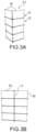
- it makes it possible to use the sub-assemblies to dress two facades simultaneously but also to dress a single facade by arranging the frames between them so that they are in the same plane as shown in the figure.
- Figure 3B shows the sub-assemblies to dress two facades simultaneously but also to dress a single facade by arranging the frames between them so that they are in the same plane as shown in the figure.
- each sub-assembly has on its construction a fixed angle between the frames, for example a right angle.
- a trim element 10 connects the horizontal edges of two modules M arranged one above the other.
- the covering element makes it possible to have a continuous covering improving the aesthetics of the photovoltaic structure.
- At least three corners are covered by the structures S1.
- the wind rose indicates the orientation of the facades.
- Preferably at least the south, east and west facades are equipped with modules.
- the modules are advantageously mobile in rotation around the Z axis relative to the facades by motorized means MT allowing a modification of the orientation of the modules during the day to follow the sun.
- the modules of the S1 structure mounted on the corner of the southeast facades, are oriented so that in the morning they face east and during the day they face south.
- the production of electricity is distributed throughout the day providing more power produced in the morning and evening compared to fixed modules.
- All or part of the modules can be motorized.
- the modules located at human height can be fixed to the facades so as not to hinder traffic around the house.
- all the modules have the same dimensions. As a variant, they have different dimensions and adapt to the presence of openings in the facades, which makes it possible to maximize the surface covered by the modules.
- the modules designated M' could be longer in the horizontal direction to cover the entire surface between the corner and the window F.
- each subset comprises a single module.
- the modules of a façade can be adjusted individually. Alternatively, they are integral in rotation and are therefore oriented at the same time.
- the structure S2 comprises a mast 105 and modules M fixed by their rear face to the mast.
- the mast 105 can be made in a single piece or in several assembled parts similar to the uprights of the sub-assemblies of the structure S2.
- the structure S3 is intended to be arranged along a facade.
- the structure S3 comprises two masts 205 extending vertically and arranged parallel to each other and separated by a distance in the horizontal direction corresponding to the dimension in the horizontal direction of a module.
- the mast 205 has the shape of a rectangular parallelepiped with a square cross section, the largest dimension of which is intended to extend vertically.
- the tallest dimension of the mast is referred to as the “mast height”.
- the mast has four faces extending vertically.
- the mast is hollow, it is for example obtained by profiling or extrusion.
- the mast has in one of the vertical faces a groove 214 extending vertically over the entire height of the mast.
- the interior of the mast forms a rail or slide for a carriage 216 which will be described later.
- the groove 214 makes it possible to connect the carriage to the module.
- the two masts are arranged relative to each other so that their grooves 214 face each other.
- the structure also includes two carriages 216, one configured to slide in one of the masts and the other to slide in the other mast.
- the carriages include means for automatically locking in position along the mast.
- the carriage comprises a frame 218 provided with two fingers 220 aligned and pushed away from each other towards the outside by means of a spring interposed between them.
- the outer dimensions of the carriage are substantially the inner dimensions of the mast, thus the carriage is directly guided by the inner faces of the mast.
- the fingers 220 have a free end 222 in the form of a ramp inclined downwards, the function of which will be described below.
- the mast comprises pairs of windows 224. Each pair comprises a first window made in a face of the mast perpendicular to that comprising the groove 214 and a second window in the face of the mast to that comprising the first window.
- the windows 224 of a pair are aligned horizontally.
- the pairs of windows are distributed along the height of the mast corresponding to a position of a module.
- the distance between two successive 224 windows in the vertical direction substantially corresponds to the dimension of a module in the vertical direction.
- the pairs of windows 224 form interlocking positions.
- the masts further comprise a window 225 in the lower part of the face comprising the groove 214, for the introduction of the carriage into the mast.
- Each carriage 214 also includes a leg 226 allowing attachment to a module.
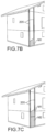
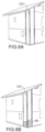
- the two masts 205 are fixed along a facade of a dwelling by their lower longitudinal ends in the ground or the foundation of the dwelling, and their longitudinal ends at the overhang of the roof for example ( Figure 7A ).
- the masts are arranged at a distance from the facade, for example at a distance of the order of 10 mm.
- the mast 205 which is not located at the corner of the building is advantageously fixed to the ground and to the overhang of the roof. Alternatively it can be fixed on the facade but. Preferably the mast 205 located at the corner of the building is fixed to the ground and to the overhang of the roof.
- the two masts are positioned relative to each other so that the grooves 214 face each other.
- each mast is mounted a carriage 216 through a window 225 by bringing the fingers together.
- a module is fixed to the legs 226 of the carriages, for example by screw-nut assemblies.
- Each carriage 214 can then slide vertically in a mast, the fingers being retracted.
- each finger is opposite a window and the fingers 220 move apart from each other under the action of the spring and each protrude at through the window 224 ensuring a locking in the vertical position of the carriage ( figure 6D ).
- the first module M1 intended to be at the top of the facade set up between the two masts at the bottom of these.
- This module being generally in the shade due to the eaves, it is preferably formed of a decorative element advantageously imitating photovoltaic modules. The module is slid upwards to reach the first self-locking position.
- a second M2 module and its carriages are placed between and in the masts ( Fig. 7C ).
- the module is a photovoltaic module.
- the module M1 is also pushed upwards.
- each mast has a window located in a face opposite to that facing the facade allowing the trolley to be introduced. It is then possible to assemble the modules and the carriages prior to their installation in and between the masts.
- the trolleys are locked in the vertical position manually, for example by inserting pins through the masts and maintaining the modules on the masts.
- two carriages are implemented per module.
- four carriages are implemented, two carriages fixed to each vertical edge of a module improving the guiding of modules along the masts.
- the structure uses carriages 316 similar to the carriages 216 of the structure S3.
- the mast 305 is solid and has grooves 314 forming a slide for the carriages. THE grooves are made in two perpendicular faces of the mast intended to be perpendicular to the facades to be covered.
- Through windows 324 are made along the mast 305, open into the grooves 314 and are configured to receive a finger 320 of the carriage. Notches (not visible) aligned with the windows are made inside the grooves to accommodate the other finger 320 of the carriage.
- the manufacture of the S4 structure is similar to that of the S3 structure.
- the different stages are represented on the figures 8A to 8E .
- structure S5 comprising a mast 305 and modules M, the mechanical connection between the modules and the mast being of the dovetail or ball joint type.
- the mast comprises a groove 328 extending vertically, forming a mortise and the modules each comprising a tenon 330 which is slid into the mortise.
- Means for immobilizing the modules in the vertical position are provided, for example these means comprise a pin passing through the mast, the weight of each module coming to rest on this pin.
- Modules are mounted on either side of the mast along its vertical axis.
- the grooves are oriented relative to each other so that the modules on one side of the vertical axis are oriented perpendicular to the modules located on the other side of the vertical axis.
- the structure is adapted to cover the corner of a dwelling.
- the modules can form between them an angle of between 90° and 180°.
- a single mast is used.
- the modules can be supported by two masts.
- a mast of circular section it has a diameter of 60 mm and a material thickness of a few mm
- the section in the case of a square section hollow mast, the section has the external dimensions of 60 mm ⁇ 60 mm for and a material thickness of a few mm.
- the electrical connectors are integrated into the mast or masts, facilitating assembly.
- the connectors are preferably mounted in the mast 305 located at the corner of the building.
- the mast has a square section with a beveled angle intended to face the angle and the groove housing the connector 32 is made in the beveled angle.
- the electrical connection between the module and the connectors is advantageously automatic by mounting the module on the mast.
- each module mounted on the facades are subject to frequent shading.
- each module is then equipped with a static converter to improve production efficiency.
- the use of such a converter allows direct connection to 230 V, which simplifies the electrical network.
- the converter is a micro-inverter type converter.
- connection is obtained by a single-phase 230V cable 34 and sealed connectors 36 for each module.
- the connectors 36 are distributed along the cable. For example, overmolding of the connectors is carried out in order to guarantee their tightness.
- the converters used are contactless converters with inductive transfer simplifying the making of the electrical connections in the structure S4.
- each module carries on its rear face a primary 38 and the mast carries a fixed manner at each location of a module a secondary 40.
- the primary and the secondary are positioned so that, when mounting the module on the mast at its location, the primary is next to the secondary allowing inductive transfers.
- the cable connecting the secondaries is integrated into the mast, for example like cable 34 on the figure 10 .
- the module slides vertically in the groove of the mast and when it reaches its location the primary is automatically located opposite the secondary. No additional login action is required.
- the primary is located in an upper part of the module.
- Advantageously foolproofing means are provided to correctly position the module relative to the mast and ensure that the primary is facing the secondary.
- the primary is located in a middle zone of the module, thus the primary is always facing the secondary.
- the assembly of this structure is particularly fast since the electrical connections are made simultaneously with the assembly of the modules and automatically. Everything is prepared in the workshop allowing a reduced assembly time on site. The person performing the installation slides the modules along the module or modules and when they are in the desired position, they connect electrically.
- contactless converters with inductive transfer limits the risks of incorrect wiring, simplifies and makes the connection more reliable, in fact there is no risk of making the wrong polarity, and the risks of corrosion are reduced. In addition, a great integration discretion is obtained, since the amount of cable required is reduced.
- converters being bidirectional, they advantageously offer the possibility of integrating other functionalities into the structure. Indeed, it can be envisaged to replace certain modules by elements making it possible to emit light, for example electroluminescent diodes to light up a terrace, or even to integrate the diodes into the photovoltaic modules, by luminous elements for the purpose of decoration, by elements fulfilling building service functions, such as ventilation, energy storage, etc., or reflective elements allowing solar energy to be redirected towards other buildings.
- elements making it possible to emit light, for example electroluminescent diodes to light up a terrace, or even to integrate the diodes into the photovoltaic modules, by luminous elements for the purpose of decoration, by elements fulfilling building service functions, such as ventilation, energy storage, etc., or reflective elements allowing solar energy to be redirected towards other buildings.
- modules having additional functions applies to all the embodiments, whether converters, in particular contactless converters, are used or not.
- the photovoltaic structure according to the invention is particularly suitable for the implementation of bifacial modules, i.e. which convert light into electricity on their two faces.
- bifacial modules i.e. which convert light into electricity on their two faces.
- Such modules make it possible to increase the amount of energy that can be produced, for example it can be increased by 5% to 20%.
- the facade or facades is or are covered with a clear coating or a clear paint, which reflects the radiation on the back of the bifacial modules.
- the modules are not glued to the facade but there is generally a clearance of 1 cm to several cm between the facade and the face of the facing module.
- the light can pass and the bifaciality coefficient is increased.
- module efficiency can be improved by effective cooling by natural convection in the air gap between the facade and the module.
- a detached house is equipped at its 4 angles with photovoltaic structures according to the invention.
- the house has a rectangular ground plan with four facades, each facing a cardinal point.
- Such an installation makes it possible to generate an installed peak power of the order of 7 kWp, which is sufficient to supply a conventional average dwelling, or even to recharge an electric vehicle.
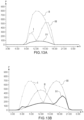
- having the modules in four different orientations makes it possible to distribute the production during the day by modifying the production profile. This makes it possible to “smooth” and “spread” production over the day, thus reducing the harmful impact of a “peak” in production in the middle of the day. It thus makes it possible to offer more energy in the morning and in the evening and to better correspond to the energy needs of the dwelling.
- Curve I represents the power produced by the modules of the structure on the east facade
- curve Il represents the power produced by the modules of the structure on the south facade
- curve III represents the power produced by the modules of the structure on the facade west
- curve IV represents the power produced by the modules of the structure on the north facade.
- the production is distributed between the facades bringing more power produced at the beginning and at the end of the day.
- Solar production intervening more at times when the occupants of the house consume energy, the self-consumption rate of energy is improved.
- the invention makes it possible to integrate modules into the facades in a harmonious manner while taking into account construction constraints, in particular the presence of external insulation. It facilitates the installation of the modules and reduces the installation time of the modules. Furthermore, it makes it possible to combine the functions by using modules having several functions and/or by combining photovoltaic modules with modules fulfilling other functions. Furthermore, the photovoltaic structure offers a high level of safety, particularly with regard to the risk of fire, because the device is not integrated into the roof.
- the photovoltaic structure is particularly suitable for dressing the facades of individual houses, but it also applies to the facades of apartment buildings, the facades of industrial buildings and the facades of office buildings.
Landscapes
- Engineering & Computer Science (AREA)
- Architecture (AREA)
- Civil Engineering (AREA)
- Structural Engineering (AREA)
- Roof Covering Using Slabs Or Stiff Sheets (AREA)
- Photovoltaic Devices (AREA)
Claims (15)
- Photovoltaikstruktur, die bestimmt ist, um mindestens einen Bereich einer Gebäudefassade zu bedecken, mindestens einen Mast (5, 105, 205, 305) beinhaltend, der eine Längsachse aufweist, die bestimmt ist, vertikal ausgerichtet zu werden, und Photovoltaikmodule (M), die am Mast befestigt sind, wobei der Mast (5, 105, 205, 305) selbsttragend ist und ein erstes unteres Längsende beinhaltet, das konfiguriert ist, um am Boden befestigt zu werden, und ein zweites oberes Längsende, das konfiguriert ist, um an einem oberen Bereich des Gebäudes befestigt zu werden,
dadurch gekennzeichnet, dass sie erste Photovoltaikmodule auf einer Seite der Längsachse des Mastes und zweite Photovoltaikmodule auf der anderen Seite der Längsachse des Mastes beinhaltet, wobei die ersten und zweiten Photovoltaikmodule so zueinander ausgerichtet sind, dass sie eine Ecke miteinander bilden, und dass, wenn der Mast entlang einer Ecke des Gebäudes montiert wird, die ersten Photovoltaikmodule einen Bereich einer ersten Fassade bedecken und die zweiten Photovoltaikmodule einen Bereich einer zweiten Fassade bedecken, wobei sich die erste und die zweite Fassade auf dem Niveau der Ecke treffen. - Photovoltaikstruktur nach Anspruch 1, Mittel zum elektrischen Anschluss der Photovoltaikmodule an eine externe Anlage beinhaltend, die in den mindestens einen Mast integriert ist.
- Photovoltaikstruktur nach Anspruch 1 oder 2, wobei die Photovoltaikmodule drehbar um die Längsachse des Mastes beweglich am Mast montiert sind, um ihre Winkelausrichtung um den Mast herum verändern zu können, wobei die Photovoltaikstruktur insbesondere motorisierte Mittel beinhaltet, die konfiguriert sind, um die Ausrichtung der Photovoltaikmodule zu verändern.
- Photovoltaikstruktur nach einem der Ansprüche 1 bis 3, wobei mindestens ein Mast (205, 305) und die Photovoltaikmodule so konfiguriert sind, dass die Photovoltaikmodule (M) geeignet sind, vertikal dem Mast (205, 305) entlang zu gleiten, bis die gewünschte Position erreicht wird, wobei die Photovoltaikstruktur insbesondere mindestens eine Längsnut (214, 314) beinhaltet, die am Mast gebildet ist, wobei mindestens ein montierter Schlitten (216, 316) in der Nut (214, 314) gleitet, wobei ein Photovoltaikmodul (M) am Schlitten (216, 316) befestigt ist und Verriegelungsmittel des Moduls entlang dem Mast (205, 305), und wobei optional die Verriegelungsmittel mindestens einen Finger (220) beinhalten, der vom Schlitten getragenen wird, wobei der Finger (220) in einer Richtung quer zur Längsachse des Mastes (205) beweglich ist und elastisch nach außen rückstellbar, und Fenster (224) im Mast an den verschiedenen Positionen der Photovoltaikmodule entlang des Mastes, wobei der Finger (220) konfiguriert ist, um mit den Fenstern (224) zusammenzuwirken und das Modul an der Position des Fensters (224) zu verriegeln, und wobei, erneut optional, die Verriegelungsmittel unidirektional sind, wobei die Verriegelungsmittel eine Verschiebung in einer Richtung des Schlittens (214) ermöglichen unter Einwirkung einer Kraft in der Verschiebungsrichtung entlang der Längsrichtung des Mastes (205).
- Photovoltaikstruktur nach einem der vorhergehenden Ansprüche, die mindestens einen weiteren Mast beinhaltet, so dass die Photovoltaikmodule von zwei parallelen gegenüberliegenden Kanten gehalten werden.
- Photovoltaikstruktur nach einem der vorhergehenden Ansprüche, einen Konverter für jedes Photovoltaikmodul beinhaltend, und wobei optional der Konverter ein kontaktloser Konverter mit induktiver Übertragung ist, eine Primäre auf der hinteren Seite des Photovoltaikmoduls beinhaltet und eine Sekundäre auf dem Mast, und wobei, wenn das Photovoltaikmodul am Mast montiert ist, die Primäre automatisch der Sekundären zugewandt ist.
- Photovoltaikstruktur nach einem der Ansprüche 1 bis 6, ein Modul beinhaltend, das eine zusätzliche Funktion mit Bezug auf die Photovoltaikmodule aufweist oder eine andere Funktion als die der Photovoltaikmodule.
- Photovoltaikstruktur nach einem der vorhergehenden Ansprüche, wobei die Photovoltaikmodule geeignet sind, Lichtenergie auf ihren beiden Seiten zu konvertieren.
- Gebäude, mehrere Fassaden beinhaltend, wobei mindestens eine Photovoltaikstruktur nach einem der Ansprüche 1 bis 8 mindestens einen Bereich mindestens einer Fassade des Gebäudes abdeckt, wobei der mindestens eine Mast am Boden und an einem oberen Bereich des Gebäudes befestigt ist, und insbesondere an jeder Ecke eine Photovoltaikstruktur beinhaltet.
- Gebäude nach Anspruch 9, eine Wärmedämmschicht beinhaltend, die eine Außenfassade bildet, wobei das erste Längsende des mindestens einen Mastes an einem Streifenfundament befestigt ist, und wobei das zweite Längsende des mindestens einen Mastes an einem Überstand des Daches befestigt ist.
- Gebäude nach einem der Ansprüche 9 bis 10, wobei die mindestens eine Struktur in Bezug auf eine Fassade so verlegt ist, dass zwischen einer hinteren Seite der Photovoltaikmodule und der Fassade des Gebäudes ein Zwischenraum besteht, beispielsweise in der Größenordnung von einem Zentimeter bis zu einigen Zentimetern.
- Verfahren zum Verkleiden mindestens eines Bereichs mindestens einer Gebäudefassade mit einer Photovoltaikstruktur nach einem der Ansprüche 1 bis 8:- Befestigung eines Mastes entlang einer Fassade durch sein erstes unteres Längsende und durch sein zweites Längsende,- Befestigung von Photovoltaikmodulen entlang des Mastes.
- Verkleidungsverfahren nach dem vorhergehenden Anspruch, wobei der Mast mehrere Unterbaugruppen beinhaltet, wobei eine erste Unterbaugruppe am Boden befestigt ist und die anderen Unterbaugruppen auf der ersten Unterbaugruppe aufgetürmt werden, und wobei die Photovoltaikmodule vor oder nach dem Auftürmen an den Unterbaugruppen befestigt werden, und wobei optional der Mast einstückig ist und die Photovoltaikmodule entlang des Mastes befestigt werden, nachdem der Mast entlang der Fassade befestigt wurde.
- Verkleidungsverfahren nach einem der Ansprüche 12 und 13 in Kombination mit Anspruch 2, einen Schritt des elektrischen Anschlusses der Photovoltaikmodule beinhaltend, im Hinblick auf einen Anschluss an eine externe Anlage, wobei dieser Schritt gleichzeitig mit dem mechanischen Zusammenbau der Struktur stattfindet, und wobei optional der mindestens eine Mast entlang einer Ecke zwischen zwei Fassaden angeordnet ist.
- Verkleidungsverfahren nach einem der Ansprüche 12 bis 13 in Kombination mit Anspruch 4, wobei mindestens ein Modul auf dem Niveau eines unteren Bereichs des Mastes am Mast montiert wird, und nach oben gedrückt wird, bis es seine endgültige Position erreicht.
Applications Claiming Priority (1)
| Application Number | Priority Date | Filing Date | Title |
|---|---|---|---|
| FR2012015A FR3116552B1 (fr) | 2020-11-23 | 2020-11-23 | Structure photovoltaïque destinée à couvrir au moins une partie d’au moins une façade d’un batiment |
Publications (2)
| Publication Number | Publication Date |
|---|---|
| EP4002684A1 EP4002684A1 (de) | 2022-05-25 |
| EP4002684B1 true EP4002684B1 (de) | 2023-07-19 |
Family
ID=74045948
Family Applications (1)
| Application Number | Title | Priority Date | Filing Date |
|---|---|---|---|
| EP21208388.5A Active EP4002684B1 (de) | 2020-11-23 | 2021-11-16 | Fotovoltaikstruktur zum bedecken von mindestens einem teil mindestens einer gebäudefassade |
Country Status (2)
| Country | Link |
|---|---|
| EP (1) | EP4002684B1 (de) |
| FR (1) | FR3116552B1 (de) |
Families Citing this family (1)
| Publication number | Priority date | Publication date | Assignee | Title |
|---|---|---|---|---|
| FR3141709A1 (fr) | 2022-11-04 | 2024-05-10 | Conception De Facade Et Faconnage | Kit d’habillage de parois par des panneaux photovoltaiques |
Family Cites Families (5)
| Publication number | Priority date | Publication date | Assignee | Title |
|---|---|---|---|---|
| US20100183443A1 (en) * | 2009-01-16 | 2010-07-22 | Steve Thorne | Integrated wind turbine and solar energy collector |
| ITMI20120496A1 (it) * | 2012-03-28 | 2013-09-29 | Emanuele Lanteri | Sistema di pannelli di conversione di energia solare applicabile a superfici verticali |
| CN103216052A (zh) | 2013-01-25 | 2013-07-24 | 冯刚克 | 建筑一体化的太阳能电池组件幕墙与屋面 |
| KR102032448B1 (ko) * | 2018-02-07 | 2019-10-15 | 크린빌(주) | 베란다 난간 설치형 태양열전지판 거치체 |
| KR102126011B1 (ko) * | 2020-01-09 | 2020-06-23 | 채종술 | 충진매질이 충진된 양면형 태양광방음패널을 이용한 수직형 방음벽과 방음벽 시공방법 |
-
2020
- 2020-11-23 FR FR2012015A patent/FR3116552B1/fr active Active
-
2021
- 2021-11-16 EP EP21208388.5A patent/EP4002684B1/de active Active
Also Published As
| Publication number | Publication date |
|---|---|
| EP4002684A1 (de) | 2022-05-25 |
| FR3116552A1 (fr) | 2022-05-27 |
| FR3116552B1 (fr) | 2023-03-31 |
Similar Documents
| Publication | Publication Date | Title |
|---|---|---|
| EP2435647B1 (de) | Carport vorgesehen mit photovoltaischen solarpaneele | |
| US7190531B2 (en) | Concentrating type solar collection and daylighting system within glazed building envelopes | |
| WO2002084044A1 (fr) | Toile photogeneratrice et support pour une telle toile | |
| US20150326175A1 (en) | System and method of rooftop solar energy production | |
| EP3060727B1 (de) | Sonnenblende mit einem festen teil und einem motorisierten beweglichen teil mit jeweils fotovoltaikzellen | |
| CA2684545A1 (fr) | Bati support d'un panneau tel que panneau photoelectrique et paroi exterieure d'un batiment comportant de tels batis | |
| WO2011023903A2 (fr) | Systeme de montage de modules photovoltaiques | |
| CA2726084A1 (fr) | Dispositif de support de modules de recuperation d'energie solaire, unite de recuperation d'energie solaire et procede de montage de modules de recuperation d'energie solaire | |
| EP4002684B1 (de) | Fotovoltaikstruktur zum bedecken von mindestens einem teil mindestens einer gebäudefassade | |
| FR2943369A1 (fr) | Profile et systeme de fixation et d'etancheite pour la realisation d'une toiture solaire, et toiture solaire obtenue | |
| EP2718635B1 (de) | Befestigungs- und dichtungssystem zur erzeugung eines solardaches und damit erzeugtes solardach | |
| WO2010055229A1 (fr) | Installation de couverture de protection contre le soleil | |
| US11264939B2 (en) | Exterior siding material with integrated solar panel | |
| US11463043B2 (en) | Internally reflective solar panel system | |
| FR3068721B1 (fr) | Structure de veranda a toiture integree dans l'epaisseur du cheneau | |
| KR101641872B1 (ko) | 건물 부착형 태양광 모듈 고정 프레임 | |
| WO2024083468A1 (fr) | Toitures et facades vegetalisees photovoltaïques | |
| FR2965671A1 (fr) | Dispositif d'egalisation de potentiel de panneaux solaires. | |
| FR2982298A1 (fr) | Habitation modulaire. | |
| AU2012216279B2 (en) | Modular building | |
| FR3063339A1 (fr) | Ensemble de production d'energie solaire avec montage integre et gestion de l'eau et procede pour fournir celui-ci | |
| FR3103888A1 (fr) | Système d’intégration d’un absorbeur d’énergie solaire à un bâtiment | |
| EP2639528A1 (de) | Modulare Fotovoltaikanlage mit vereinfachter Montage, und Aluminiumuntergestell für diese Anlage | |
| FR2958308A1 (fr) | Element de facade prefabrique | |
| FR3041084A1 (fr) | Panneau solaire destine a etre monte verticalement, et ensemble comprenant au moins un tel panneau et au moins un poteau de fixation. |
Legal Events
| Date | Code | Title | Description |
|---|---|---|---|
| PUAI | Public reference made under article 153(3) epc to a published international application that has entered the european phase |
Free format text: ORIGINAL CODE: 0009012 |
|
| STAA | Information on the status of an ep patent application or granted ep patent |
Free format text: STATUS: REQUEST FOR EXAMINATION WAS MADE |
|
| 17P | Request for examination filed |
Effective date: 20211201 |
|
| AK | Designated contracting states |
Kind code of ref document: A1 Designated state(s): AL AT BE BG CH CY CZ DE DK EE ES FI FR GB GR HR HU IE IS IT LI LT LU LV MC MK MT NL NO PL PT RO RS SE SI SK SM TR |
|
| GRAP | Despatch of communication of intention to grant a patent |
Free format text: ORIGINAL CODE: EPIDOSNIGR1 |
|
| STAA | Information on the status of an ep patent application or granted ep patent |
Free format text: STATUS: GRANT OF PATENT IS INTENDED |
|
| RIC1 | Information provided on ipc code assigned before grant |
Ipc: H02S 20/26 20140101AFI20230316BHEP |
|
| INTG | Intention to grant announced |
Effective date: 20230404 |
|
| GRAS | Grant fee paid |
Free format text: ORIGINAL CODE: EPIDOSNIGR3 |
|
| GRAA | (expected) grant |
Free format text: ORIGINAL CODE: 0009210 |
|
| STAA | Information on the status of an ep patent application or granted ep patent |
Free format text: STATUS: THE PATENT HAS BEEN GRANTED |
|
| AK | Designated contracting states |
Kind code of ref document: B1 Designated state(s): AL AT BE BG CH CY CZ DE DK EE ES FI FR GB GR HR HU IE IS IT LI LT LU LV MC MK MT NL NO PL PT RO RS SE SI SK SM TR |
|
| REG | Reference to a national code |
Ref country code: GB Ref legal event code: FG4D Free format text: NOT ENGLISH |
|
| REG | Reference to a national code |
Ref country code: CH Ref legal event code: EP |
|
| REG | Reference to a national code |
Ref country code: DE Ref legal event code: R096 Ref document number: 602021003602 Country of ref document: DE |
|
| REG | Reference to a national code |
Ref country code: IE Ref legal event code: FG4D Free format text: LANGUAGE OF EP DOCUMENT: FRENCH |
|
| REG | Reference to a national code |
Ref country code: LT Ref legal event code: MG9D |
|
| REG | Reference to a national code |
Ref country code: NL Ref legal event code: MP Effective date: 20230719 |
|
| REG | Reference to a national code |
Ref country code: AT Ref legal event code: MK05 Ref document number: 1590493 Country of ref document: AT Kind code of ref document: T Effective date: 20230719 |
|
| PG25 | Lapsed in a contracting state [announced via postgrant information from national office to epo] |
Ref country code: NL Free format text: LAPSE BECAUSE OF FAILURE TO SUBMIT A TRANSLATION OF THE DESCRIPTION OR TO PAY THE FEE WITHIN THE PRESCRIBED TIME-LIMIT Effective date: 20230719 |
|
| PG25 | Lapsed in a contracting state [announced via postgrant information from national office to epo] |
Ref country code: GR Free format text: LAPSE BECAUSE OF FAILURE TO SUBMIT A TRANSLATION OF THE DESCRIPTION OR TO PAY THE FEE WITHIN THE PRESCRIBED TIME-LIMIT Effective date: 20231020 |
|
| PG25 | Lapsed in a contracting state [announced via postgrant information from national office to epo] |
Ref country code: IS Free format text: LAPSE BECAUSE OF FAILURE TO SUBMIT A TRANSLATION OF THE DESCRIPTION OR TO PAY THE FEE WITHIN THE PRESCRIBED TIME-LIMIT Effective date: 20231119 |
|
| PG25 | Lapsed in a contracting state [announced via postgrant information from national office to epo] |
Ref country code: SE Free format text: LAPSE BECAUSE OF FAILURE TO SUBMIT A TRANSLATION OF THE DESCRIPTION OR TO PAY THE FEE WITHIN THE PRESCRIBED TIME-LIMIT Effective date: 20230719 Ref country code: RS Free format text: LAPSE BECAUSE OF FAILURE TO SUBMIT A TRANSLATION OF THE DESCRIPTION OR TO PAY THE FEE WITHIN THE PRESCRIBED TIME-LIMIT Effective date: 20230719 Ref country code: PT Free format text: LAPSE BECAUSE OF FAILURE TO SUBMIT A TRANSLATION OF THE DESCRIPTION OR TO PAY THE FEE WITHIN THE PRESCRIBED TIME-LIMIT Effective date: 20231120 Ref country code: NO Free format text: LAPSE BECAUSE OF FAILURE TO SUBMIT A TRANSLATION OF THE DESCRIPTION OR TO PAY THE FEE WITHIN THE PRESCRIBED TIME-LIMIT Effective date: 20231019 Ref country code: LV Free format text: LAPSE BECAUSE OF FAILURE TO SUBMIT A TRANSLATION OF THE DESCRIPTION OR TO PAY THE FEE WITHIN THE PRESCRIBED TIME-LIMIT Effective date: 20230719 Ref country code: LT Free format text: LAPSE BECAUSE OF FAILURE TO SUBMIT A TRANSLATION OF THE DESCRIPTION OR TO PAY THE FEE WITHIN THE PRESCRIBED TIME-LIMIT Effective date: 20230719 Ref country code: IS Free format text: LAPSE BECAUSE OF FAILURE TO SUBMIT A TRANSLATION OF THE DESCRIPTION OR TO PAY THE FEE WITHIN THE PRESCRIBED TIME-LIMIT Effective date: 20231119 Ref country code: HR Free format text: LAPSE BECAUSE OF FAILURE TO SUBMIT A TRANSLATION OF THE DESCRIPTION OR TO PAY THE FEE WITHIN THE PRESCRIBED TIME-LIMIT Effective date: 20230719 Ref country code: GR Free format text: LAPSE BECAUSE OF FAILURE TO SUBMIT A TRANSLATION OF THE DESCRIPTION OR TO PAY THE FEE WITHIN THE PRESCRIBED TIME-LIMIT Effective date: 20231020 Ref country code: FI Free format text: LAPSE BECAUSE OF FAILURE TO SUBMIT A TRANSLATION OF THE DESCRIPTION OR TO PAY THE FEE WITHIN THE PRESCRIBED TIME-LIMIT Effective date: 20230719 Ref country code: AT Free format text: LAPSE BECAUSE OF FAILURE TO SUBMIT A TRANSLATION OF THE DESCRIPTION OR TO PAY THE FEE WITHIN THE PRESCRIBED TIME-LIMIT Effective date: 20230719 |
|
| PGFP | Annual fee paid to national office [announced via postgrant information from national office to epo] |
Ref country code: FR Payment date: 20231120 Year of fee payment: 3 Ref country code: DE Payment date: 20231120 Year of fee payment: 3 |
|
| PG25 | Lapsed in a contracting state [announced via postgrant information from national office to epo] |
Ref country code: PL Free format text: LAPSE BECAUSE OF FAILURE TO SUBMIT A TRANSLATION OF THE DESCRIPTION OR TO PAY THE FEE WITHIN THE PRESCRIBED TIME-LIMIT Effective date: 20230719 |
|
| PG25 | Lapsed in a contracting state [announced via postgrant information from national office to epo] |
Ref country code: ES Free format text: LAPSE BECAUSE OF FAILURE TO SUBMIT A TRANSLATION OF THE DESCRIPTION OR TO PAY THE FEE WITHIN THE PRESCRIBED TIME-LIMIT Effective date: 20230719 |
|
| PG25 | Lapsed in a contracting state [announced via postgrant information from national office to epo] |
Ref country code: SM Free format text: LAPSE BECAUSE OF FAILURE TO SUBMIT A TRANSLATION OF THE DESCRIPTION OR TO PAY THE FEE WITHIN THE PRESCRIBED TIME-LIMIT Effective date: 20230719 Ref country code: RO Free format text: LAPSE BECAUSE OF FAILURE TO SUBMIT A TRANSLATION OF THE DESCRIPTION OR TO PAY THE FEE WITHIN THE PRESCRIBED TIME-LIMIT Effective date: 20230719 Ref country code: ES Free format text: LAPSE BECAUSE OF FAILURE TO SUBMIT A TRANSLATION OF THE DESCRIPTION OR TO PAY THE FEE WITHIN THE PRESCRIBED TIME-LIMIT Effective date: 20230719 Ref country code: EE Free format text: LAPSE BECAUSE OF FAILURE TO SUBMIT A TRANSLATION OF THE DESCRIPTION OR TO PAY THE FEE WITHIN THE PRESCRIBED TIME-LIMIT Effective date: 20230719 Ref country code: DK Free format text: LAPSE BECAUSE OF FAILURE TO SUBMIT A TRANSLATION OF THE DESCRIPTION OR TO PAY THE FEE WITHIN THE PRESCRIBED TIME-LIMIT Effective date: 20230719 Ref country code: CZ Free format text: LAPSE BECAUSE OF FAILURE TO SUBMIT A TRANSLATION OF THE DESCRIPTION OR TO PAY THE FEE WITHIN THE PRESCRIBED TIME-LIMIT Effective date: 20230719 Ref country code: SK Free format text: LAPSE BECAUSE OF FAILURE TO SUBMIT A TRANSLATION OF THE DESCRIPTION OR TO PAY THE FEE WITHIN THE PRESCRIBED TIME-LIMIT Effective date: 20230719 |
|
| PLBE | No opposition filed within time limit |
Free format text: ORIGINAL CODE: 0009261 |
|
| STAA | Information on the status of an ep patent application or granted ep patent |
Free format text: STATUS: NO OPPOSITION FILED WITHIN TIME LIMIT |