EP4002684B1 - Photovoltaic structure intended for covering at least one portion of at least one façade of a building - Google Patents
Photovoltaic structure intended for covering at least one portion of at least one façade of a building Download PDFInfo
- Publication number
- EP4002684B1 EP4002684B1 EP21208388.5A EP21208388A EP4002684B1 EP 4002684 B1 EP4002684 B1 EP 4002684B1 EP 21208388 A EP21208388 A EP 21208388A EP 4002684 B1 EP4002684 B1 EP 4002684B1
- Authority
- EP
- European Patent Office
- Prior art keywords
- mast
- photovoltaic
- modules
- facade
- photovoltaic modules
- Prior art date
- Legal status (The legal status is an assumption and is not a legal conclusion. Google has not performed a legal analysis and makes no representation as to the accuracy of the status listed.)
- Active
Links
- 230000001939 inductive effect Effects 0.000 claims description 7
- 238000009413 insulation Methods 0.000 claims description 7
- 238000005253 cladding Methods 0.000 claims description 6
- 238000000034 method Methods 0.000 claims description 6
- 230000000694 effects Effects 0.000 claims description 2
- 238000000429 assembly Methods 0.000 description 14
- 238000009434 installation Methods 0.000 description 10
- 238000004519 manufacturing process Methods 0.000 description 10
- 238000010276 construction Methods 0.000 description 4
- 230000005611 electricity Effects 0.000 description 4
- 239000000463 material Substances 0.000 description 3
- 241001080024 Telles Species 0.000 description 2
- 230000009471 action Effects 0.000 description 2
- 239000011449 brick Substances 0.000 description 2
- 238000009422 external insulation Methods 0.000 description 2
- 230000010354 integration Effects 0.000 description 2
- 238000010008 shearing Methods 0.000 description 2
- OKTJSMMVPCPJKN-UHFFFAOYSA-N Carbon Chemical compound [C] OKTJSMMVPCPJKN-UHFFFAOYSA-N 0.000 description 1
- 230000000712 assembly Effects 0.000 description 1
- 230000008901 benefit Effects 0.000 description 1
- 230000002457 bidirectional effect Effects 0.000 description 1
- 229910052799 carbon Inorganic materials 0.000 description 1
- 239000011248 coating agent Substances 0.000 description 1
- 238000000576 coating method Methods 0.000 description 1
- 238000001816 cooling Methods 0.000 description 1
- 238000005260 corrosion Methods 0.000 description 1
- 230000007797 corrosion Effects 0.000 description 1
- 238000005034 decoration Methods 0.000 description 1
- 238000009826 distribution Methods 0.000 description 1
- 238000004146 energy storage Methods 0.000 description 1
- 238000001125 extrusion Methods 0.000 description 1
- 230000003100 immobilizing effect Effects 0.000 description 1
- 230000006698 induction Effects 0.000 description 1
- 239000011810 insulating material Substances 0.000 description 1
- 239000012774 insulation material Substances 0.000 description 1
- 230000004048 modification Effects 0.000 description 1
- 238000012986 modification Methods 0.000 description 1
- 239000003973 paint Substances 0.000 description 1
- 230000008569 process Effects 0.000 description 1
- 230000005855 radiation Effects 0.000 description 1
- 239000007787 solid Substances 0.000 description 1
- 230000003068 static effect Effects 0.000 description 1
- 238000009423 ventilation Methods 0.000 description 1
Images


Classifications
-
- H—ELECTRICITY
- H02—GENERATION; CONVERSION OR DISTRIBUTION OF ELECTRIC POWER
- H02S—GENERATION OF ELECTRIC POWER BY CONVERSION OF INFRARED RADIATION, VISIBLE LIGHT OR ULTRAVIOLET LIGHT, e.g. USING PHOTOVOLTAIC [PV] MODULES
- H02S20/00—Supporting structures for PV modules
- H02S20/20—Supporting structures directly fixed to an immovable object
- H02S20/22—Supporting structures directly fixed to an immovable object specially adapted for buildings
- H02S20/26—Building materials integrated with PV modules, e.g. façade elements
-
- Y—GENERAL TAGGING OF NEW TECHNOLOGICAL DEVELOPMENTS; GENERAL TAGGING OF CROSS-SECTIONAL TECHNOLOGIES SPANNING OVER SEVERAL SECTIONS OF THE IPC; TECHNICAL SUBJECTS COVERED BY FORMER USPC CROSS-REFERENCE ART COLLECTIONS [XRACs] AND DIGESTS
- Y02—TECHNOLOGIES OR APPLICATIONS FOR MITIGATION OR ADAPTATION AGAINST CLIMATE CHANGE
- Y02B—CLIMATE CHANGE MITIGATION TECHNOLOGIES RELATED TO BUILDINGS, e.g. HOUSING, HOUSE APPLIANCES OR RELATED END-USER APPLICATIONS
- Y02B10/00—Integration of renewable energy sources in buildings
- Y02B10/10—Photovoltaic [PV]
-
- Y—GENERAL TAGGING OF NEW TECHNOLOGICAL DEVELOPMENTS; GENERAL TAGGING OF CROSS-SECTIONAL TECHNOLOGIES SPANNING OVER SEVERAL SECTIONS OF THE IPC; TECHNICAL SUBJECTS COVERED BY FORMER USPC CROSS-REFERENCE ART COLLECTIONS [XRACs] AND DIGESTS
- Y02—TECHNOLOGIES OR APPLICATIONS FOR MITIGATION OR ADAPTATION AGAINST CLIMATE CHANGE
- Y02B—CLIMATE CHANGE MITIGATION TECHNOLOGIES RELATED TO BUILDINGS, e.g. HOUSING, HOUSE APPLIANCES OR RELATED END-USER APPLICATIONS
- Y02B10/00—Integration of renewable energy sources in buildings
- Y02B10/20—Solar thermal
-
- Y—GENERAL TAGGING OF NEW TECHNOLOGICAL DEVELOPMENTS; GENERAL TAGGING OF CROSS-SECTIONAL TECHNOLOGIES SPANNING OVER SEVERAL SECTIONS OF THE IPC; TECHNICAL SUBJECTS COVERED BY FORMER USPC CROSS-REFERENCE ART COLLECTIONS [XRACs] AND DIGESTS
- Y02—TECHNOLOGIES OR APPLICATIONS FOR MITIGATION OR ADAPTATION AGAINST CLIMATE CHANGE
- Y02E—REDUCTION OF GREENHOUSE GAS [GHG] EMISSIONS, RELATED TO ENERGY GENERATION, TRANSMISSION OR DISTRIBUTION
- Y02E10/00—Energy generation through renewable energy sources
- Y02E10/50—Photovoltaic [PV] energy
Definitions
- the present invention relates to a photovoltaic structure intended to be mounted along at least part of at least one facade of a building, in particular of a detached house.
- Photovoltaic modules for generating electricity are usually mounted on the roofs of buildings.
- the facades of the buildings offer large surfaces available to receive these modules.
- the photovoltaic modules can be fixed directly to the facade, or via an intermediate structure fixed to the facade.
- the thermal insulation is generally done from the outside, ie a thermal insulating material generally in the form of a plate is fixed for example on the concrete or brick wall. It is not possible to fix the modules or a support structure in the thermal insulation material which is not sufficiently resistant from a mechanical point of view.
- the document CN 103806580 describes a supporting structure of photovoltaic modules which is fixed to the concrete or brick wall by means of screws which cross all the thickness of the thermal insulation.
- the thermal insulation has a significant thickness, several centimeters, for example 10 cm, which implies the implementation of long screws, the structure is then cantilevered and the screws then undergo a significant shearing force. .
- the document KR 20200006161 A describes photovoltaic modules according to the prior art.
- a photovoltaic structure intended to cover at least part of at least one facade of a building of simplified assembly
- a photovoltaic structure comprising at least one mast intended to be oriented vertically along the facade, at least one photovoltaic module fixed to the mast, the mast comprising fixing means at its longitudinal ends so fixing the mast along at least one facade of a building.
- the structure according to the invention is self-supporting thanks to the implementation of at least one mast and does not require fixing through the thermal insulation.
- the lower longitudinal end of the mast is fixed in the foundation sole of the building and the upper longitudinal end of the mast is fixed to the overhang of the roof of the building.
- the structure is particularly advantageous for mounting along the corners of a building in which fixing to the wall becomes very complex.
- the structure comprises for example three masts, a first mast running along the junction between the two facades, a second mast running along one of the facades and the third mast running along the other facade and modules being mounted between or on the first mast and the second mast and the first mast and the third mast.
- the electrical connection means of the photovoltaic modules are partly or completely carried by the mast or masts.
- One of the subjects of the present application is a photovoltaic structure intended to cover at least part of a facade of a building, comprising at least one mast having a longitudinal axis intended to be oriented vertically and photovoltaic modules fixed to the mast, said mast being self-supporting and comprising a first lower longitudinal end configured to be fixed to the ground and a second upper longitudinal end configured to be attached to an upper part of the building.
- the photovoltaic structure comprises means for electrical connection of the photovoltaic modules to an external installation integrated into the at least one mast.
- the photovoltaic structure comprises first photovoltaic modules on one side of the longitudinal axis of the mast, and second photovoltaic modules on the other side of the longitudinal axis of the mast, the first and second photovoltaic modules being oriented relative to each other so as to form an angle between them and so that, when the mast is mounted along a corner of the building, the first photovoltaic modules cover part of a first facade and the second photovoltaic modules cover a part of a second facade, the first and the second facades meeting at said angle.
- photovoltaic modules are rotatably mounted on the mast around the longitudinal axis of the mast so as to be able to modify their angular orientation around the mast.
- the photovoltaic structure can comprise motorized means configured to modify the orientation of the photovoltaic modules.
- the at least one mast and the photovoltaic modules are configured so that the photovoltaic modules are capable of sliding vertically along the mast until reaching the desired location.
- the structure may comprise at least one longitudinal groove formed in the mast, at least one carriage mounted to slide in the groove, a photovoltaic module being fixed to the carriage, and module locking means along the mast.
- the locking means comprise at least one finger carried by the carriage, said finger movable in a direction transverse to the longitudinal axis of the mast and elastically biased outwards, and windows in the mast at the different locations of the modules photovoltaic along the mast, said finger being configured to cooperate with said window is to lock the module at the location of said window.
- the locking means are unidirectional, the locking means allowing movement in one direction of the carriage under the effect of a force in said direction of movement along the longitudinal direction of the mast.
- the photovoltaic structure can comprise at least one other mast so that the photovoltaic modules are held by two opposite parallel edges.
- the photovoltaic structure comprises a converter for each photovoltaic module.
- the converter can be a contactless converter with inductive transfer, comprising a primary on a rear face of the photovoltaic module and a secondary on the mast and, when the photovoltaic module is mounted on the mast, the primary can be automatically facing the secondary.
- the photovoltaic structure can comprise a module having an additional function with respect to the photovoltaic modules or a function different from that of the photovoltaic modules.
- the photovoltaic modules are capable of converting light energy on their two faces.
- Another object of the present application is a building comprising several facades, at least one photovoltaic structure according to the invention covering at least a part of at least one facade of said building, the at least one mast being fixed to the ground and to a part top of the building.
- the building can have a photovoltaic structure at each corner.
- the building comprises a layer of thermal insulation forming an exterior facade, the first longitudinal end of the at least one mast is fixed in a foundation sole, and the second longitudinal end of the at least one mast is fixed to an overhang of the roof.
- the at least one structure can be placed relative to a facade so that a clearance exists between a rear face of the photovoltaic modules and the facade of the building, for example of the order of one centimeter to a few centimeters.
- the mast can comprise several sub-assemblies, a first sub-assembly being fixed to the ground and the other sub-assemblies being stacked on the first sub-assembly, and the photovoltaic modules can be fixed on the sub-assemblies before or after their stacking .
- the mast is a single piece and the photovoltaic modules are fixed along the mast after fixing the mast along the facade.
- the covering method may comprise a step of electrical connection of the photovoltaic modules with a view to connection to an external installation, said step taking place simultaneously with the mechanical assembly of the structure.
- the at least one mast can be arranged along an angle between two facades.
- At least one module is mounted in the mast at the level of a lower part of the mast and is pushed upwards until it reaches its final location.
- a photovoltaic module will be referred to as a “module” for simplicity.
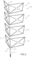
- a photovoltaic structure S1 making it possible to cover at least part of the facades of a building, in particular the facades of an individual dwelling house.
- the structure S1 comprises several sub-assemblies E intended to be arranged one above the other so as to form the complete structure represented in exploded view on the figure 2 .
- a sub-assembly E comprises an upright 2 with an axis Z, and two support frames 4 on either side of the upright 2.
- One of the vertical uprights of each frame is formed by the upright 2.
- the Z axis is intended to be oriented vertically.
- Each carrier frame advantageously comprises a stiffening structure 6 formed by two elements mounted crosswise and connecting the vertices of the frame together.
- the frames 4 are articulated in rotation on the upright 2 around the axis Z, for example hinges are provided between an edge of each frame 4 and the upright 2.
- the upright 2 is advantageously hollow, preferably it is formed by a tube, which allows the passage of the electrical connection means of the modules.
- the electrical connection between the electrical connection means of each upright is automatic during assembly of the sub-assemblies.
- the electrical connection means can be made using dedicated sealed connectors or a so-called “contactless” connection system by induction.
- the tube is of circular section, as a variant it can have a polygonal section, such as square.
- the P modules represented on the figures 3A to 3C in transparency are fixed by their rear face on the carrier frame.
- the longitudinal ends of the vertical upright 2 are advantageously configured to cooperate with the longitudinal ends of the uprights of the other sub-assemblies, so as to form a self-supporting mast 5 over the height of the facade.
- self-supporting mast means a mast which deforms little or not at all under its own weight and under the weight of the photovoltaic panel(s), and without the need for mechanical support along it.
- the lower longitudinal end 2.1 of an upright 2 forms a male part intended to penetrate into an upper longitudinal end forming a female part, of the mast of the module located directly below.
- the lower longitudinal end of the upright of the sub-assembly located at the bottom of the structure cooperates with fixing means 7 in the ground, for example in the foundation of the building, for example it is a foundation screw.
- the upper end of the upright of the sub-assembly located at the top of the structure is intended to cooperate with means of attachment to the upper part of the building, for example the roof overhang or a high point of the facade.
- anchor points at the corners of the frames located opposite the vertical upright 2. These anchor points are offset from the corner of the building which is an area on which fixing due to the external insulation can be complex.
- the mast can be fixed directly in the facade via for example two brackets at 90° arranged on the corner of the building.
- the same principle of facade fixing can be implemented by adapting the anchor points to the facade.
- the stiffening structure serves as a support for a converter, for example of the micro-inverter type 8 of the module which will be described later.
- the connection between the microinverter and the module can be wired or contactless type with inductive transfer.
- a module M is attached to each frame and is electrically connected to its micro-inverter.
- the foundation screw is fixed in the foundation opposite the edge connecting two facades.
- the mast is arranged at a distance from the facade allowing the mast to work mechanically, for example due to vibrations due to the wind, thermal expansion, without coming into contact with the facade.
- the distance between the mast and the facade is advantageously of the order of 10 mm.
- the first sub-assembly is mounted in the fixing screw, the lower longitudinal end of the upright being housed in the fixing screw, then the second sub-assembly is mounted in the first sub-assembly by inserting the lower longitudinal end of its amount in the upper longitudinal end of the amount of the first subset. This operation is repeated with the other sub-assemblies until the desired height is reached, preferably until the top of the facade is reached.
- the assembly of the sub-assemblies is for example carried out by means of a lifting platform.
- the upper longitudinal end of the last assembled sub-assembly is fixed to the building, for example to the roof overhang.
- the assembly of the subsets automatically ensures the electrical connection of the electrical connection means of the subsets to one another.
- the structure is connected to the building's distribution network via a cable at the top or bottom of the mast.
- Means for locking the sub-assemblies together can be provided.
- the sub-assemblies are locked together via pins passing through the mast.
- screws passing through the mast can also be used to secure two sub-assemblies.
- one or more mechanical self-locking systems that can be unlocked by a lever accessible when the mast is mounted can be used, or means ensuring securing of the assembly by screwing.
- a structure comprising a self-supporting mast to which modules are attached.
- This rotational joint has the advantage of being able to easily adapt the structure to different angle values.
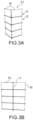
- it makes it possible to use the sub-assemblies to dress two facades simultaneously but also to dress a single facade by arranging the frames between them so that they are in the same plane as shown in the figure.
- Figure 3B shows the sub-assemblies to dress two facades simultaneously but also to dress a single facade by arranging the frames between them so that they are in the same plane as shown in the figure.
- each sub-assembly has on its construction a fixed angle between the frames, for example a right angle.
- a trim element 10 connects the horizontal edges of two modules M arranged one above the other.
- the covering element makes it possible to have a continuous covering improving the aesthetics of the photovoltaic structure.
- At least three corners are covered by the structures S1.
- the wind rose indicates the orientation of the facades.
- Preferably at least the south, east and west facades are equipped with modules.
- the modules are advantageously mobile in rotation around the Z axis relative to the facades by motorized means MT allowing a modification of the orientation of the modules during the day to follow the sun.
- the modules of the S1 structure mounted on the corner of the southeast facades, are oriented so that in the morning they face east and during the day they face south.
- the production of electricity is distributed throughout the day providing more power produced in the morning and evening compared to fixed modules.
- All or part of the modules can be motorized.
- the modules located at human height can be fixed to the facades so as not to hinder traffic around the house.
- all the modules have the same dimensions. As a variant, they have different dimensions and adapt to the presence of openings in the facades, which makes it possible to maximize the surface covered by the modules.
- the modules designated M' could be longer in the horizontal direction to cover the entire surface between the corner and the window F.
- each subset comprises a single module.
- the modules of a façade can be adjusted individually. Alternatively, they are integral in rotation and are therefore oriented at the same time.
- the structure S2 comprises a mast 105 and modules M fixed by their rear face to the mast.
- the mast 105 can be made in a single piece or in several assembled parts similar to the uprights of the sub-assemblies of the structure S2.
- the structure S3 is intended to be arranged along a facade.
- the structure S3 comprises two masts 205 extending vertically and arranged parallel to each other and separated by a distance in the horizontal direction corresponding to the dimension in the horizontal direction of a module.
- the mast 205 has the shape of a rectangular parallelepiped with a square cross section, the largest dimension of which is intended to extend vertically.
- the tallest dimension of the mast is referred to as the “mast height”.
- the mast has four faces extending vertically.
- the mast is hollow, it is for example obtained by profiling or extrusion.
- the mast has in one of the vertical faces a groove 214 extending vertically over the entire height of the mast.
- the interior of the mast forms a rail or slide for a carriage 216 which will be described later.
- the groove 214 makes it possible to connect the carriage to the module.
- the two masts are arranged relative to each other so that their grooves 214 face each other.
- the structure also includes two carriages 216, one configured to slide in one of the masts and the other to slide in the other mast.
- the carriages include means for automatically locking in position along the mast.
- the carriage comprises a frame 218 provided with two fingers 220 aligned and pushed away from each other towards the outside by means of a spring interposed between them.
- the outer dimensions of the carriage are substantially the inner dimensions of the mast, thus the carriage is directly guided by the inner faces of the mast.
- the fingers 220 have a free end 222 in the form of a ramp inclined downwards, the function of which will be described below.
- the mast comprises pairs of windows 224. Each pair comprises a first window made in a face of the mast perpendicular to that comprising the groove 214 and a second window in the face of the mast to that comprising the first window.
- the windows 224 of a pair are aligned horizontally.
- the pairs of windows are distributed along the height of the mast corresponding to a position of a module.
- the distance between two successive 224 windows in the vertical direction substantially corresponds to the dimension of a module in the vertical direction.
- the pairs of windows 224 form interlocking positions.
- the masts further comprise a window 225 in the lower part of the face comprising the groove 214, for the introduction of the carriage into the mast.
- Each carriage 214 also includes a leg 226 allowing attachment to a module.
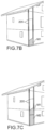
- the two masts 205 are fixed along a facade of a dwelling by their lower longitudinal ends in the ground or the foundation of the dwelling, and their longitudinal ends at the overhang of the roof for example ( Figure 7A ).
- the masts are arranged at a distance from the facade, for example at a distance of the order of 10 mm.
- the mast 205 which is not located at the corner of the building is advantageously fixed to the ground and to the overhang of the roof. Alternatively it can be fixed on the facade but. Preferably the mast 205 located at the corner of the building is fixed to the ground and to the overhang of the roof.
- the two masts are positioned relative to each other so that the grooves 214 face each other.
- each mast is mounted a carriage 216 through a window 225 by bringing the fingers together.
- a module is fixed to the legs 226 of the carriages, for example by screw-nut assemblies.
- Each carriage 214 can then slide vertically in a mast, the fingers being retracted.
- each finger is opposite a window and the fingers 220 move apart from each other under the action of the spring and each protrude at through the window 224 ensuring a locking in the vertical position of the carriage ( figure 6D ).
- the first module M1 intended to be at the top of the facade set up between the two masts at the bottom of these.
- This module being generally in the shade due to the eaves, it is preferably formed of a decorative element advantageously imitating photovoltaic modules. The module is slid upwards to reach the first self-locking position.
- a second M2 module and its carriages are placed between and in the masts ( Fig. 7C ).
- the module is a photovoltaic module.
- the module M1 is also pushed upwards.
- each mast has a window located in a face opposite to that facing the facade allowing the trolley to be introduced. It is then possible to assemble the modules and the carriages prior to their installation in and between the masts.
- the trolleys are locked in the vertical position manually, for example by inserting pins through the masts and maintaining the modules on the masts.
- two carriages are implemented per module.
- four carriages are implemented, two carriages fixed to each vertical edge of a module improving the guiding of modules along the masts.
- the structure uses carriages 316 similar to the carriages 216 of the structure S3.
- the mast 305 is solid and has grooves 314 forming a slide for the carriages. THE grooves are made in two perpendicular faces of the mast intended to be perpendicular to the facades to be covered.
- Through windows 324 are made along the mast 305, open into the grooves 314 and are configured to receive a finger 320 of the carriage. Notches (not visible) aligned with the windows are made inside the grooves to accommodate the other finger 320 of the carriage.
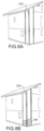
- the manufacture of the S4 structure is similar to that of the S3 structure.
- the different stages are represented on the figures 8A to 8E .
- structure S5 comprising a mast 305 and modules M, the mechanical connection between the modules and the mast being of the dovetail or ball joint type.
- the mast comprises a groove 328 extending vertically, forming a mortise and the modules each comprising a tenon 330 which is slid into the mortise.
- Means for immobilizing the modules in the vertical position are provided, for example these means comprise a pin passing through the mast, the weight of each module coming to rest on this pin.
- Modules are mounted on either side of the mast along its vertical axis.
- the grooves are oriented relative to each other so that the modules on one side of the vertical axis are oriented perpendicular to the modules located on the other side of the vertical axis.
- the structure is adapted to cover the corner of a dwelling.
- the modules can form between them an angle of between 90° and 180°.
- a single mast is used.
- the modules can be supported by two masts.
- a mast of circular section it has a diameter of 60 mm and a material thickness of a few mm
- the section in the case of a square section hollow mast, the section has the external dimensions of 60 mm ⁇ 60 mm for and a material thickness of a few mm.
- the electrical connectors are integrated into the mast or masts, facilitating assembly.
- the connectors are preferably mounted in the mast 305 located at the corner of the building.
- the mast has a square section with a beveled angle intended to face the angle and the groove housing the connector 32 is made in the beveled angle.
- the electrical connection between the module and the connectors is advantageously automatic by mounting the module on the mast.
- each module mounted on the facades are subject to frequent shading.
- each module is then equipped with a static converter to improve production efficiency.
- the use of such a converter allows direct connection to 230 V, which simplifies the electrical network.
- the converter is a micro-inverter type converter.
- connection is obtained by a single-phase 230V cable 34 and sealed connectors 36 for each module.
- the connectors 36 are distributed along the cable. For example, overmolding of the connectors is carried out in order to guarantee their tightness.
- the converters used are contactless converters with inductive transfer simplifying the making of the electrical connections in the structure S4.
- each module carries on its rear face a primary 38 and the mast carries a fixed manner at each location of a module a secondary 40.
- the primary and the secondary are positioned so that, when mounting the module on the mast at its location, the primary is next to the secondary allowing inductive transfers.
- the cable connecting the secondaries is integrated into the mast, for example like cable 34 on the figure 10 .
- the module slides vertically in the groove of the mast and when it reaches its location the primary is automatically located opposite the secondary. No additional login action is required.
- the primary is located in an upper part of the module.
- Advantageously foolproofing means are provided to correctly position the module relative to the mast and ensure that the primary is facing the secondary.
- the primary is located in a middle zone of the module, thus the primary is always facing the secondary.
- the assembly of this structure is particularly fast since the electrical connections are made simultaneously with the assembly of the modules and automatically. Everything is prepared in the workshop allowing a reduced assembly time on site. The person performing the installation slides the modules along the module or modules and when they are in the desired position, they connect electrically.
- contactless converters with inductive transfer limits the risks of incorrect wiring, simplifies and makes the connection more reliable, in fact there is no risk of making the wrong polarity, and the risks of corrosion are reduced. In addition, a great integration discretion is obtained, since the amount of cable required is reduced.
- converters being bidirectional, they advantageously offer the possibility of integrating other functionalities into the structure. Indeed, it can be envisaged to replace certain modules by elements making it possible to emit light, for example electroluminescent diodes to light up a terrace, or even to integrate the diodes into the photovoltaic modules, by luminous elements for the purpose of decoration, by elements fulfilling building service functions, such as ventilation, energy storage, etc., or reflective elements allowing solar energy to be redirected towards other buildings.
- elements making it possible to emit light, for example electroluminescent diodes to light up a terrace, or even to integrate the diodes into the photovoltaic modules, by luminous elements for the purpose of decoration, by elements fulfilling building service functions, such as ventilation, energy storage, etc., or reflective elements allowing solar energy to be redirected towards other buildings.
- modules having additional functions applies to all the embodiments, whether converters, in particular contactless converters, are used or not.
- the photovoltaic structure according to the invention is particularly suitable for the implementation of bifacial modules, i.e. which convert light into electricity on their two faces.
- bifacial modules i.e. which convert light into electricity on their two faces.
- Such modules make it possible to increase the amount of energy that can be produced, for example it can be increased by 5% to 20%.
- the facade or facades is or are covered with a clear coating or a clear paint, which reflects the radiation on the back of the bifacial modules.
- the modules are not glued to the facade but there is generally a clearance of 1 cm to several cm between the facade and the face of the facing module.
- the light can pass and the bifaciality coefficient is increased.
- module efficiency can be improved by effective cooling by natural convection in the air gap between the facade and the module.
- a detached house is equipped at its 4 angles with photovoltaic structures according to the invention.
- the house has a rectangular ground plan with four facades, each facing a cardinal point.
- Such an installation makes it possible to generate an installed peak power of the order of 7 kWp, which is sufficient to supply a conventional average dwelling, or even to recharge an electric vehicle.
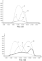
- having the modules in four different orientations makes it possible to distribute the production during the day by modifying the production profile. This makes it possible to “smooth” and “spread” production over the day, thus reducing the harmful impact of a “peak” in production in the middle of the day. It thus makes it possible to offer more energy in the morning and in the evening and to better correspond to the energy needs of the dwelling.
- Curve I represents the power produced by the modules of the structure on the east facade
- curve Il represents the power produced by the modules of the structure on the south facade
- curve III represents the power produced by the modules of the structure on the facade west
- curve IV represents the power produced by the modules of the structure on the north facade.
- the production is distributed between the facades bringing more power produced at the beginning and at the end of the day.
- Solar production intervening more at times when the occupants of the house consume energy, the self-consumption rate of energy is improved.
- the invention makes it possible to integrate modules into the facades in a harmonious manner while taking into account construction constraints, in particular the presence of external insulation. It facilitates the installation of the modules and reduces the installation time of the modules. Furthermore, it makes it possible to combine the functions by using modules having several functions and/or by combining photovoltaic modules with modules fulfilling other functions. Furthermore, the photovoltaic structure offers a high level of safety, particularly with regard to the risk of fire, because the device is not integrated into the roof.
- the photovoltaic structure is particularly suitable for dressing the facades of individual houses, but it also applies to the facades of apartment buildings, the facades of industrial buildings and the facades of office buildings.
Description
La présente invention se rapporte à une structure photovoltaïque destinée à être montée le long d'au moins une partie d'au moins une façade d'un bâtiment, notamment d'une maison individuelle.The present invention relates to a photovoltaic structure intended to be mounted along at least part of at least one facade of a building, in particular of a detached house.
Les modules photovoltaïques en vue de générer de l'électricité sont généralement montés sur les toits des bâtiments. Or les façades des bâtiments offrent des surfaces importantes disponibles pour recevoir ces modules. Une implantation sur plusieurs façades du bâtiment, par exemple sur les façades orientées à l'est, au sud et à l'ouest, permet en outre de maximiser le temps pendant lequel de l'électricité est produite au cours de la journée.Photovoltaic modules for generating electricity are usually mounted on the roofs of buildings. However, the facades of the buildings offer large surfaces available to receive these modules. Installation on several facades of the building, for example on the facades facing east, south and west, also makes it possible to maximize the time during which electricity is produced during the day.
Les modules photovoltaïques peuvent être fixés directement sur la façade, ou via une structure intermédiaire fixée sur la façade. Or pour les constructions nouvelles et pour les bâtiments rénovés, l'isolation thermique se fait généralement par l'extérieur, i.e. un matériau isolant thermique généralement sous forme de plaque est fixé par exemple sur le mur en béton ou en brique. Il n'est pas possible de fixer les modules ou une structure porteuse dans le matériau d'isolation thermique qui n'est pas suffisamment résistant d'un point de vue mécanique. Le document
En outre, le montage peut être complexe et peut détériorer l'isolation thermique Le document
C'est par conséquent un but de la présente invention d'offrir une structure photovoltaïque ne présentant pas les inconvénients ci-dessus.It is therefore an object of the present invention to provide a photovoltaic structure that does not have the above drawbacks.
C'est également un but de la présente invention d'offrir une structure photovoltaïque destinée à couvrir au moins une partie d'au moins une façade d'un bâtiment de montage simplifiée
Le but énoncé ci-dessus est atteint par une structure photovoltaïque comportant au moins un mât destiné à être orienté verticalement le long de la façade, au moins un module photovoltaïque fixé au mât, le mât comportant des moyens de fixation à ses extrémités longitudinales de sorte à fixer le mât le long d'au moins une façade d'un bâtiment.It is also an object of the present invention to provide a photovoltaic structure intended to cover at least part of at least one facade of a building of simplified assembly
The object stated above is achieved by a photovoltaic structure comprising at least one mast intended to be oriented vertically along the facade, at least one photovoltaic module fixed to the mast, the mast comprising fixing means at its longitudinal ends so fixing the mast along at least one facade of a building.
La structure selon l'invention est autoportante grâce à la mise en oeuvre d'au moins un mât et ne requiert pas la fixation à travers l'isolant thermique. Par exemple l'extrémité longitudinale inférieure du mât est fixée dans la semelle de fondation du bâtiment et l'extrémité longitudinale supérieure du mât est fixée au débord du toit du bâtiment.The structure according to the invention is self-supporting thanks to the implementation of at least one mast and does not require fixing through the thermal insulation. For example, the lower longitudinal end of the mast is fixed in the foundation sole of the building and the upper longitudinal end of the mast is fixed to the overhang of the roof of the building.
La structure est particulièrement avantageuse pour un montage le long des angles d'un bâtiment dans lesquels une fixation au mur devient très complexe. La structure comporte par exemple trois mâts, un premier mât courant le long de la jonction entre les deux façades, un deuxième mât courant le long d'une des façades et le troisième mât courant le long de l'autre façade et des modules étant montés entre ou sur le premier mât et le deuxième mât et le premier mât et le troisième mât.The structure is particularly advantageous for mounting along the corners of a building in which fixing to the wall becomes very complex. The structure comprises for example three masts, a first mast running along the junction between the two facades, a second mast running along one of the facades and the third mast running along the other facade and modules being mounted between or on the first mast and the second mast and the first mast and the third mast.
De manière préférée, les moyens de connexion électrique des modules photovoltaïques sont portés en partie ou complètement par le ou les mâts.Preferably, the electrical connection means of the photovoltaic modules are partly or completely carried by the mast or masts.
Un des objets de la présente demande est une structure photovoltaïque destinée à couvrir au moins une partie d'une façade d'un bâtiment, comportant au moins un mât présentant un axe longitudinal destiné à être orienté verticalement et des modules photovoltaïques fixés au mât, ledit mât étant autoporteur et comportant une première extrémité longitudinale inférieure configurée pour être fixée au sol et une deuxième extrémité longitudinale supérieure configurée pour être fixée à une partie supérieure du bâtiment.One of the subjects of the present application is a photovoltaic structure intended to cover at least part of a facade of a building, comprising at least one mast having a longitudinal axis intended to be oriented vertically and photovoltaic modules fixed to the mast, said mast being self-supporting and comprising a first lower longitudinal end configured to be fixed to the ground and a second upper longitudinal end configured to be attached to an upper part of the building.
De manière préférée, la structure photovoltaïque comporte des moyens de connexion électrique des modules photovoltaïques à une installation extérieure intégrés dans le au moins un mât.Preferably, the photovoltaic structure comprises means for electrical connection of the photovoltaic modules to an external installation integrated into the at least one mast.
Dans un exemple de réalisation, la structure photovoltaïque comporte des premiers modules photovoltaïques d'un côté de l'axe longitudinal du mât, et des deuxièmes modules photovoltaïques de l'autre côté de l'axe longitudinal du mât, les premiers et deuxièmes modules photovoltaïques étant orientés l'un par rapport à l'autre de sorte à former entre eux un angle et de sorte que, lorsque le mât est monté le long d'un angle du bâtiment, les premiers modules photovoltaïques couvrent une partie d'une première façade et les deuxièmes modules photovoltaïques couvrent une partie d'une deuxième façade, la première et la deuxième façades se rejoignant au niveau dudit angle.In an exemplary embodiment, the photovoltaic structure comprises first photovoltaic modules on one side of the longitudinal axis of the mast, and second photovoltaic modules on the other side of the longitudinal axis of the mast, the first and second photovoltaic modules being oriented relative to each other so as to form an angle between them and so that, when the mast is mounted along a corner of the building, the first photovoltaic modules cover part of a first facade and the second photovoltaic modules cover a part of a second facade, the first and the second facades meeting at said angle.
Très avantageusement, es modules photovoltaïques sont montés mobiles en rotation sur le mât autour de l'axe longitudinal du mât de sorte à pouvoir modifier leur orientation angulaire autour du mât. La structure photovoltaïque peut comporter des moyens motorisés configurés pour modifier l'orientation des modules photovoltaïques.Very advantageously, photovoltaic modules are rotatably mounted on the mast around the longitudinal axis of the mast so as to be able to modify their angular orientation around the mast. The photovoltaic structure can comprise motorized means configured to modify the orientation of the photovoltaic modules.
Dans un exemple de réalisation, le au moins un mât et les modules photovoltaïques sont configurés de sorte que les modules photovoltaïques soient aptes à coulisser verticalement le long du mât jusqu'à atteindre l'emplacement souhaité.In an exemplary embodiment, the at least one mast and the photovoltaic modules are configured so that the photovoltaic modules are capable of sliding vertically along the mast until reaching the desired location.
La structure peut comporter au moins une rainure longitudinale formée dans le mât, au moins un chariot monté coulissant dans la rainure, un module photovoltaïque étant fixé au chariot, et des moyens de verrouillage du module le long du mât. Par exemple, les moyens de verrouillage comportent au moins un doigt porté par le chariot, ledit doigt mobile dans une direction transversale à l'axe longitudinal du mât et rappeler élastiquement vers l'extérieur, et des fenêtres dans le mât aux différents emplacements des modules photovoltaïques le long du mât, ledit doigt étant configuré pour coopérer avec lesdites fenêtre est verrouiller le module à l'emplacement de ladite fenêtre.The structure may comprise at least one longitudinal groove formed in the mast, at least one carriage mounted to slide in the groove, a photovoltaic module being fixed to the carriage, and module locking means along the mast. For example, the locking means comprise at least one finger carried by the carriage, said finger movable in a direction transverse to the longitudinal axis of the mast and elastically biased outwards, and windows in the mast at the different locations of the modules photovoltaic along the mast, said finger being configured to cooperate with said window is to lock the module at the location of said window.
Avantageusement, les moyens de verrouillage sont unidirectionnels, les moyens de verrouillage permettant un déplacement dans un sens du chariot sous l'effet d'un effort dans ledit sens de déplacement le long de la direction longitudinale du mât.Advantageously, the locking means are unidirectional, the locking means allowing movement in one direction of the carriage under the effect of a force in said direction of movement along the longitudinal direction of the mast.
La structure photovoltaïque peut comporter au moins un autre mât de sorte que les modules photovoltaïques soient maintenus par deux bords opposés parallèles.The photovoltaic structure can comprise at least one other mast so that the photovoltaic modules are held by two opposite parallel edges.
Selon une caractéristique additionnelle, la structure photovoltaïque comporte un convertisseur pour chaque module photovoltaïque. Le convertisseur peut être un convertisseur sans contact à transfert inductif, comportant un primaire sur une face arrière du module photovoltaïque et un secondaire sur le mât et, lorsque le module photovoltaïque est monté sur le mât, le primaire peut être automatiquement en regard du secondaire.According to an additional characteristic, the photovoltaic structure comprises a converter for each photovoltaic module. The converter can be a contactless converter with inductive transfer, comprising a primary on a rear face of the photovoltaic module and a secondary on the mast and, when the photovoltaic module is mounted on the mast, the primary can be automatically facing the secondary.
La structure photovoltaïque peut comporter un module présentant une fonction supplémentaire par rapport aux modules photovoltaïques ou une fonction différente de celle des modules photovoltaïques.The photovoltaic structure can comprise a module having an additional function with respect to the photovoltaic modules or a function different from that of the photovoltaic modules.
Selon une caractéristique additionnelle, les modules photovoltaïques sont aptes à convertir l'énergie lumineuse sur leurs deux faces.According to an additional characteristic, the photovoltaic modules are capable of converting light energy on their two faces.
Un autre objet de la présente demande est un bâtiment comportant plusieurs façades, au moins une structure photovoltaïque selon l'invention recouvrant au moins une partie d'au moins une façade dudit bâtiment, le au moins un mât étant fixé au sol et à une partie supérieure du bâtiment.Another object of the present application is a building comprising several facades, at least one photovoltaic structure according to the invention covering at least a part of at least one facade of said building, the at least one mast being fixed to the ground and to a part top of the building.
Le bâtiment peut comporter une structure photovoltaïque à chaque angle.The building can have a photovoltaic structure at each corner.
Par exemple le bâtiment, comporte une couche d'isolation thermique formant une façade extérieure, la première extrémité longitudinale du au moins un mât est fixée dans une semelle de fondation, et la deuxième extrémité longitudinale du au moins un mât est fixé à un débord du toit.For example, the building comprises a layer of thermal insulation forming an exterior facade, the first longitudinal end of the at least one mast is fixed in a foundation sole, and the second longitudinal end of the at least one mast is fixed to an overhang of the roof.
La au moins une structure peut être posée par rapport à une façade de sorte qu'un jeu existe entre une face arrière des modules photovoltaïques et la façade du bâtiment, par exemple de l'ordre d'un centimètre à quelques centimètres.The at least one structure can be placed relative to a facade so that a clearance exists between a rear face of the photovoltaic modules and the facade of the building, for example of the order of one centimeter to a few centimeters.
Un autre objet de la présente demande est un procédé d'habillage d'au moins une partie d'au moins une façade d'un bâtiment avec une structure photovoltaïque selon l'invention :
- fixation d'un mât le long d'une façade par sa première extrémité longitudinale inférieure et par sa deuxième extrémité longitudinale,
- fixation de modules photovoltaïques le long du mât.
- fixing a mast along a facade by its first lower longitudinal end and by its second longitudinal end,
- fixing photovoltaic modules along the mast.
Le mât peut comporter plusieurs sous-ensembles, un premier sous-ensemble étant fixe au sol et les autres sous-ensembles étant empilés sur le premier sous-ensemble, et les modules photovoltaïques peuvent être fixés sur les sous-ensembles avant ou après leur empilage.The mast can comprise several sub-assemblies, a first sub-assembly being fixed to the ground and the other sub-assemblies being stacked on the first sub-assembly, and the photovoltaic modules can be fixed on the sub-assemblies before or after their stacking .
Par exemple, le mât est un seul tenant et les modules photovoltaïques sont fixés le long du mât après la fixation du mât le long de la façade.For example, the mast is a single piece and the photovoltaic modules are fixed along the mast after fixing the mast along the facade.
Le procédé d'habillage peut comporter une étape de connexion électrique des modules photovoltaïques en vue d'une connexion vers une installation extérieure, ladite étape ayant lieu simultanément à l'assemblage mécanique de la structure.The covering method may comprise a step of electrical connection of the photovoltaic modules with a view to connection to an external installation, said step taking place simultaneously with the mechanical assembly of the structure.
Le au moins un mât peut être disposé le long d'un angle entre deux façades.The at least one mast can be arranged along an angle between two facades.
Selon un mode d'assemblage, au moins un module est monté dans le mât au niveau d'une partie inférieure du mât et est poussé vers le haut jusqu'à atteindre son emplacement final.According to one mode of assembly, at least one module is mounted in the mast at the level of a lower part of the mast and is pushed upwards until it reaches its final location.
La présente invention sera mieux comprise sur la base de la description qui va suivre et des dessins en annexe sur lesquels:
- les
figures 1A et 1B sont des vues en perspective d'un exemple de réalisation d'un sous-ensemble d'une structure photovoltaïque dans deux positions. - la
figure 2 est une vue en perspective en éclaté de la structure photovoltaïque obtenue avec les sous-ensembles desfigures 1A et 1B sans les modules photovoltaïques. - la
figure 3A est une vue de lafigure 2 avec les modules photovoltaïques. - la
figure 3B est une vue en perspective d'une structure photovoltaïque présentant une orientation des modules photovoltaïques différente de celle des modules photovoltaïques de lafigure 3A . - la
figure 3C est une vue en perspective d'une structure photovoltaïque présentant une orientation des modules photovoltaïques différente de celle des modules photovoltaïques de lafigure 3A . - la
figure 4 est une représentation schématique d'une maison individuelle équipée de la structure de lafigure 3A . - la
figure 5 est une vue en perspective d'un autre exemple de structure photovoltaïque. - la
figure 6A est une vue en perspective d'un autre exemple de structure photovoltaïque. - la
figure 6B est une vue en transparence de la structure de lafigure 6A . - la
figure 6C est une vue en perspective d'un chariot mis en oeuvre dans la structure de lafigure 6A . - la
figure 6D est une vue en coupe transversale de lafigure 6A le long du plan A-A. - la
figure 6E est une vue de lafigure 6A sans le module. - les
figures 7A à 7E sont différentes vues des différentes étapes d'habillage d'une façade d'une maison individuelle avec la structure de lafigure 6A . - les
figures 8A à 8E sont différentes vues des différentes étapes d'habillage d'une façade d'une maison individuelle avec la structure recouvrant un angle d'une maison individuelle. - la
figure 8F est une vue en coupe transversale de la structure de lafigure 8E . - la
figure 9A est une en perspective d'une structure photovoltaïque selon un autre exemple de réalisation. - la
figure 9B est une vue en coupe transversale de la structure de lafigure 6A le long du plan B-B. - la
figure 10 est une vue en coupe d'un mât d'une structure photovoltaïque. - la
figure 11A est une vue en perspective d'un exemple de connectique. - la
figure 11B est une vue de derrière d'un mât d'une structure photovoltaïque intégrant la connectique de lafigure 11A . - la
figure 12A est une vue partielle d'une structure photovoltaïque mettant en oeuvre des convertisseurs sans contact à transfert inductif. - la
figure 12B est une vue en coupe transversale de la structure de lafigure 12B le long du plan C-C. - la
figure 13A est une représentation graphique de la variation de puissance produite en Watt au mois de janvier en fonction de l'heure de la journée h par une structure telle que celle de lafigure 3A . - la
figure 13B est une représentation graphique de la variation de puissance produite P en Watt au mois de juin en fonction de l'heure de la journée h par une structure telle que celle de lafigure 3A .
- THE
figures 1A and 1B are perspective views of an embodiment of a subassembly of a photovoltaic structure in two positions. - there
figure 2 is an exploded perspective view of the photovoltaic structure obtained with the subsets of thefigures 1A and 1B without photovoltaic modules. - there
Figure 3A is a view of thefigure 2 with photovoltaic modules. - there
Figure 3B is a perspective view of a photovoltaic structure having an orientation of the photovoltaic modules different from that of the photovoltaic modules of theFigure 3A . - there
Fig. 3C is a perspective view of a photovoltaic structure having an orientation of the photovoltaic modules different from that of the photovoltaic modules of theFigure 3A . - there
figure 4 is a schematic representation of a detached house equipped with the structure of theFigure 3A . - there
figure 5 is a perspective view of another example of a photovoltaic structure. - there
Figure 6A is a perspective view of another example of a photovoltaic structure. - there
figure 6B is a transparent view of the structure of theFigure 6A . - there
Fig. 6C is a perspective view of a carriage implemented in the structure of theFigure 6A . - there
figure 6D is a cross-sectional view of theFigure 6A along plane AA. - there
Figure 6E is a view of theFigure 6A without the mod. - THE
figures 7A to 7E are different views of the different stages of cladding a facade of a detached house with the structure of theFigure 6A . - THE
figures 8A to 8E are different views of the different stages of cladding a facade of a single-family house with the structure covering a corner of a single-family house. - there
figure 8F is a cross-sectional view of the structure of thefigure 8E . - there
figure 9A is a perspective view of a photovoltaic structure according to another exemplary embodiment. - there
Figure 9B is a cross-sectional view of the structure of theFigure 6A along plane BB. - there
figure 10 is a sectional view of a mast of a photovoltaic structure. - there
figure 11A is a perspective view of an example of connectors. - there
figure 11B is a view from behind of a mast of a photovoltaic structure integrating the connectors of thefigure 11A . - there
Figure 12A is a partial view of a photovoltaic structure using inductive transfer contactless converters. - there
figure 12B is a cross-sectional view of the structure of thefigure 12B along the plane CC. - there
Figure 13A is a graphical representation of the variation in power produced in Watts in the month of January as a function of the time of day h by a structure such as that of theFigure 3A . - there
Figure 13B is a graphic representation of the variation in power produced P in Watt in the month of June as a function of the hour of the day h by a structure such as that of theFigure 3A .
Dans la description qui va suivre, un module photovoltaïque sera désigné par « module » à des fins de simplicité.In the following description, a photovoltaic module will be referred to as a “module” for simplicity.
Sur les
La structure S1 comporte plusieurs sous-ensembles E destinés à être disposés les uns au-dessus des autres de sorte à former la structure complète représentée en éclaté sur la
Un sous-ensemble E comporte un montant 2 d'axe Z, et deux cadres porteurs 4 de part et d'autre du montant 2. Un des montants verticaux de chaque cadre est formé par le montant 2. L'axe Z est destiné à être orienté verticalement.A sub-assembly E comprises an
Chaque cadre porteur comporte avantageusement une structure de rigidification 6 formée par deux éléments montés en croix et reliant les sommets du cadre entre eux.Each carrier frame advantageously comprises a
Dans l'exemple représenté, les cadres 4 sont articulés en rotation sur le montant 2 autour de l'axe Z, par exemple des charnières sont prévues entre un bord de chaque cadre 4 et le montant 2.In the example shown, the
Le montant 2 est avantageusement creux, de préférence il est formé par un tube, ce qui permet le passage des moyens de connexion électrique des modules. De préférence, la connexion électrique entre les moyens de connexion électrique de chaque montant est automatique lors de l'assemblage des sous-ensembles. Les moyens de connexion électrique peuvent être réalisés à l'aide de connecteurs étanches dédiés ou d'un système de connectique dite « sans contact » par induction.The
Dans l'exemple le tube est de section circulaire, en variante il peut avoir une section polygonale, telle que carrée.In the example the tube is of circular section, as a variant it can have a polygonal section, such as square.
Les modules P représentés sur les
Les extrémités longitudinales du montant vertical 2 sont avantageusement configurées pour coopérer avec les extrémités longitudinales des montants des autres sous-ensembles, de sorte à former un mât 5 autoporteur sur la hauteur de la façade. On entend par « mât autoporteur » un mât qui ne se déforme pas ou peu sous son propre poids et sous le poids du ou des panneaux photovoltaïques, et sans nécessité de maintien mécanique le long de celui-ci.The longitudinal ends of the
Dans l'exemple représenté, l'extrémité longitudinale inférieure 2.1 d'un montant 2 forme une partie mâle destinée à pénétrer dans une extrémité longitudinale supérieure formant une partie femelle, du mât du module situé directement en dessous.In the example shown, the lower longitudinal end 2.1 of an
L'extrémité longitudinale inférieure du montant du sous-ensemble situé au bas de la structure coopère avec des moyens de fixation 7 dans le sol, par exemple dans la fondation du bâtiment par exemple il s'agit d'une vis de fondation.The lower longitudinal end of the upright of the sub-assembly located at the bottom of the structure cooperates with fixing means 7 in the ground, for example in the foundation of the building, for example it is a foundation screw.
L'extrémité supérieure du montant du sous-ensemble située en haut de la structure est destinée à coopérer avec des moyens de fixation à la partie supérieure du bâtiment, par exemple le débord de toiture ou un point haut de la façade.The upper end of the upright of the sub-assembly located at the top of the structure is intended to cooperate with means of attachment to the upper part of the building, for example the roof overhang or a high point of the facade.
En variante, on peut envisager un maintien de la structure sur la façade par l'intermédiaire de point d'ancrage aux angles des cadres situés à l'opposé du montant vertical 2. Ces points d'ancrage sont déportés de l'angle du bâtiment qui est une zone sur laquelle la fixation du fait de l'isolation extérieure peut être complexe.Alternatively, one can consider maintaining the structure on the facade by means of anchor points at the corners of the frames located opposite the
Dans le cas où la fixation du mât ne peut être réalisée en partie haute et/ou basse du bâtiment, le mât peut être fixé directement dans la façade via par exemple deux équerres à 90° disposées sur l'angle du bâtiment. Dans le cas d'un bâtiment sans débord de toiture, le même principe de fixation en façade peut être mis en oeuvre en adaptant les points d'ancrage à la façade. De manière également avantageuse, la structure de rigidification sert de support à un convertisseur, par exemple de type micro-onduleur 8 du module qui sera décrit plus tard. La connexion entre le micro-onduleur et le module peut être filaire ou de type sans contact à transfert inductif.If the fixing of the mast cannot be carried out in the upper and/or lower part of the building, the mast can be fixed directly in the facade via for example two brackets at 90° arranged on the corner of the building. In the case of a building without a roof overhang, the same principle of facade fixing can be implemented by adapting the anchor points to the facade. Also advantageously, the stiffening structure serves as a support for a converter, for example of the micro-inverter type 8 of the module which will be described later. The connection between the microinverter and the module can be wired or contactless type with inductive transfer.
Le montage de la structure photovoltaïque S1 va être décrit.The assembly of the photovoltaic structure S1 will be described.
Par exemple un module M est fixé à chaque cadre et est raccordé électriquement à son micro-onduleur.For example, a module M is attached to each frame and is electrically connected to its micro-inverter.
La vis de fondation est fixée dans la fondation en regard de l'arête reliant deux façades. De préférence, le mât est disposé à distance de la façade permettant au mât de travailler mécaniquement, par exemple du fait des vibrations dues au vent, des dilatations thermiques, sans entrer en contact avec la façade. La distance entre le mât et la façade est avantageusement de l'ordre de 10 mm. Le premier sous-ensemble est monté dans la vis de fixation, l'extrémité longitudinale inférieure du montant étant logée dans la vis de fixation, puis le deuxième sous-ensemble est monté dans le premier sous-ensemble en insérant l'extrémité longitudinale inférieure de son montant dans l'extrémité longitudinale supérieure du montant du premier sous-ensemble. Cette opération est répétée avec les autres sous-ensembles jusqu'à atteindre la hauteur souhaitée, de préférence jusqu'à atteindre le haut de la façade. L'assemblage des sous-ensembles est par exemple réalisé au moyen d'une nacelle élévatrice. L'extrémité longitudinale supérieure du dernier sous-ensemble assemblé est fixée au bâtiment, par exemple au débord de toit. Avantageusement l'assemblage des sous-ensembles assure automatiquement la connexion électrique des moyens de connexions électriques des sous-ensembles entre eux. La structure est reliée au réseau de distribution du bâtiment via un câble en haut ou en bas du mât.The foundation screw is fixed in the foundation opposite the edge connecting two facades. Preferably, the mast is arranged at a distance from the facade allowing the mast to work mechanically, for example due to vibrations due to the wind, thermal expansion, without coming into contact with the facade. The distance between the mast and the facade is advantageously of the order of 10 mm. The first sub-assembly is mounted in the fixing screw, the lower longitudinal end of the upright being housed in the fixing screw, then the second sub-assembly is mounted in the first sub-assembly by inserting the lower longitudinal end of its amount in the upper longitudinal end of the amount of the first subset. This operation is repeated with the other sub-assemblies until the desired height is reached, preferably until the top of the facade is reached. The assembly of the sub-assemblies is for example carried out by means of a lifting platform. The upper longitudinal end of the last assembled sub-assembly is fixed to the building, for example to the roof overhang. Advantageously, the assembly of the subsets automatically ensures the electrical connection of the electrical connection means of the subsets to one another. The structure is connected to the building's distribution network via a cable at the top or bottom of the mast.
Il peut être prévu des moyens de verrouillage des sous-ensembles entre eux. Par exemple, les sous-ensembles sont verrouillés entre eux via des goupilles traversant le mât. En variante, des vis traversant le mât peuvent également être utilisées pour solidariser deux sous-ensembles. En variante encore, un ou des systèmes autobloquants mécaniques pouvant être déverrouillés par un levier accessible lorsque le mat est monté peuvent être utilisées, ou des moyens assurant une sécurisation de l'assemblage par vissage.Means for locking the sub-assemblies together can be provided. For example, the sub-assemblies are locked together via pins passing through the mast. Alternatively, screws passing through the mast can also be used to secure two sub-assemblies. As a further variant, one or more mechanical self-locking systems that can be unlocked by a lever accessible when the mast is mounted can be used, or means ensuring securing of the assembly by screwing.
On obtient alors une structure comportant un mât autoporteur auquel sont fixés des modules.A structure is then obtained comprising a self-supporting mast to which modules are attached.
Dans le cas où les cadres sont montés mobiles en rotation autour de l'axe Z, les cadres de chaque sous-ensemble peuvent être rabattus contre une des façades, de sorte que la face arrière du module soit en regard de la façade, et est fixé à la façade. Cette fixation ne pose pas les problèmes de fixation de la structure à la façade, elle ne subit pas de cisaillement. On obtient la structure de la
Cette articulation en rotation présente l'avantage de pouvoir adapter facilement la structure à différentes valeurs d'angle. En outre elle permet d'utiliser les sous-ensembles pour habiller deux façades simultanément mais également d'habiller une seule façade en disposant les cadres entre eux de sorte qu'ils soient dans un même plan comme cela est représenté sur la
On peut envisager que chaque sous-ensemble présente à sa construction un angle fixe entre les cadres, par exemple un angle droit.It is conceivable that each sub-assembly has on its construction a fixed angle between the frames, for example a right angle.
Sur la
Sur la
Dans cet exemple au moins trois angles sont recouverts par les structures S1. La rose des vents indique l'orientation des façades. De préférence au moins les façades sud, est et ouest sont équipés de modules.In this example at least three corners are covered by the structures S1. The wind rose indicates the orientation of the facades. Preferably at least the south, east and west facades are equipped with modules.
Dans l'exemple représenté, les modules sont avantageusement mobiles en rotation autour de l'axe Z par rapport aux façades par des moyens motorisés MT permettant une modification de l'orientation des modules au cours de la journée pour suivre le soleil. Par exemple, les modules de la structure S1 montée sur l'angle des façades sud-est, sont orientés de sorte que le matin ils soient orientés vers l'est et au cours de la journée ils soient orientés vers le sud. Ainsi la production d'électricité se répartit tout au long de la journée apportant davantage de puissance produite le matin et le soir par rapport à des modules fixes.In the example shown, the modules are advantageously mobile in rotation around the Z axis relative to the facades by motorized means MT allowing a modification of the orientation of the modules during the day to follow the sun. For example, the modules of the S1 structure, mounted on the corner of the southeast facades, are oriented so that in the morning they face east and during the day they face south. Thus the production of electricity is distributed throughout the day providing more power produced in the morning and evening compared to fixed modules.
Tous les modules ou une partie d'entre eux peuvent être motorisés. Par exemple les modules situés à hauteur d'être humain peuvent être fixés aux façades afin de ne pas gêner la circulation autour de la maison.All or part of the modules can be motorized. For example, the modules located at human height can be fixed to the facades so as not to hinder traffic around the house.
Dans l'exemple représenté, tous les modules ont les mêmes dimensions. En variante ils présentent des dimensions différentes et s'adaptent à la présence d'ouvertures dans les façades, ce qui permet de maximiser la surface couverte par les modules. Par exemple sur la
En variante encore, chaque sous-ensemble comporte un seul module.As a further variant, each subset comprises a single module.
Dans l'exemple représenté sur la
Sur la
La structure S2 comporte un mât 105 et des modules M fixés par leur face arrière sur le mât. Le mât 105 peut être réalisé en une seule pièce ou en plusieurs parties assemblées similaires aux montants des sous-ensembles de la structure S2.The structure S2 comprises a
Sur les
Sur la
La structure S3 comporte deux mâts 205 s'étendant verticalement et disposés parallèlement l'un par rapport à l'autre et séparés d'une distance dans la direction horizontale correspondant à la dimension dans la direction horizontale d'un module.The structure S3 comprises two
Les deux mâts sont de structure similaire, un seul sera décrit en détail.Both masts are of similar structure, only one will be described in detail.
Dans cet exemple, le mât 205 a une forme de parallélépipède rectangle de section transversale carrée dont la plus grande dimension est destinée à s'étendre verticalement. La plus grande dimension du mât est désignée « hauteur du mât ». Le mât comporte quatre faces s'étendant verticalement.In this example, the
Dans l'exemple représenté, le mât est creux, il est par exemple obtenu par profilage ou extrusion.In the example shown, the mast is hollow, it is for example obtained by profiling or extrusion.
Le mât comporte dans une des faces verticales une rainure 214 s'étendant verticalement sur toute la hauteur du mât.The mast has in one of the vertical faces a
L'intérieur du mât forme un rail ou glissière pour un chariot 216 qui sera décrit par la suite. La rainure 214 permet de connecter le chariot au module.The interior of the mast forms a rail or slide for a
Lors de la mise en place de la structure les deux mâts sont disposés l'un par rapport à l'autre de sorte que leurs rainures 214 soient en regard.When the structure is in place, the two masts are arranged relative to each other so that their
La structure comporte également deux chariots 216, l'un configuré pour coulisser dans l'un des mâts et l'autre pour coulisser dans l'autre mât.The structure also includes two
De manière très avantageuse, les chariots comportent des moyens de verrouillage automatique en position le long du mât.Very advantageously, the carriages include means for automatically locking in position along the mast.
Sur la
Le chariot comporte un châssis 218 munies de deux doigts 220 alignés et repoussés l'un de l'autre vers l'extérieur au moyen d'un ressort interposé entre eux. De préférence, les dimensions extérieures du chariot sont sensiblement les dimensions intérieures du mât, ainsi le chariot est directement guidé par les faces intérieures du mât.The carriage comprises a frame 218 provided with two
Les doigts 220 présentent une extrémité libre 222 en forme de rampe inclinée vers le bas dont la fonction sera décrite ci-dessous. Le mât comporte des paires de fenêtres 224. Chaque paire comporte une première fenêtre réalisée dans une face du mât perpendiculaire à celle comportant la rainure 214 et une deuxième fenêtre dans la face du mât à celle comportant la première fenêtre. Les fenêtres 224 d'une paire sont alignées horizontalement.The
Les paires de fenêtres sont réparties le long de la hauteur du mât correspondant à une position d'un module. La distance entre deux fenêtres 224 successives dans la direction verticale correspond sensiblement à la dimension d'un module dans la direction verticale. Les paires de fenêtres 224 forment des positions autobloquantes.The pairs of windows are distributed along the height of the mast corresponding to a position of a module. The distance between two successive 224 windows in the vertical direction substantially corresponds to the dimension of a module in the vertical direction. The pairs of
Les mâts comportent en outre une fenêtre 225 dans la partie inférieure de la face comportant la rainure 214, pour l'introduction du chariot dans le mât.The masts further comprise a
Chaque chariot 214 comporte également une patte 226 permettant une fixation à un module.Each
La mise en place de la structure photovoltaïque S3 va maintenant être décrite. Sur les
Les deux mâts 205 sont fixés le long d'une façade d'une habitation par leurs extrémités longitudinales inférieures dans le sol ou la fondation de l'habitation, et leurs extrémités longitudinales au débord du toit par exemple (
Le mât 205 qui n'est pas situé à l'angle du bâtiment est avantageusement fixé au sol et au débord du toit. En variante il peut être fixé sur la façade mais. De préférence le mât 205 situé à l'angle du bâtiment est fixé au sol et au débord du toit.The
Les deux mâts sont positionnés l'un par rapport à l'autre de sorte que les rainures 214 soient en regard.The two masts are positioned relative to each other so that the
Dans chaque mât est monté un chariot 216 par une fenêtre 225 en rapprochant les doigts l'un de l'autre. Un module est fixé aux pattes 226 des chariots, par exemple par des ensembles vis-écrou.In each mast is mounted a
Chaque chariot 214 peut alors coulisser verticalement dans un mât, les doigts étant rétractés. Lorsqu'un chariot se retrouve au niveau d'une paire de fenêtres, chaque doigt se trouve en face d'une fenêtre et les doigts 220 s'écartent l'un de l'autre sous l'action du ressort et font saillie chacun à travers la fenêtre 224 assurant un verrouillage en position verticale du chariot (
Du fait des profils des doigts, en exerçant un effort de poussée vers le haut sur les chariots, les doigts 220 se rétractent vers l'intérieur du mât, le chariot est libéré et peut se déplacer verticalement vers le haut jusqu'à atteindre la prochaine paire de fenêtres.Due to the profiles of the fingers, by exerting an upward thrust force on the carriages, the
Sur la
Un deuxième module M2 et ses chariots sont mis en place entre et dans les mâts (
Grâce à la structure des chariots et les moyens de verrouillage les modules sécurisent la position des modules à chaque étape. En outre cette structure permet un assemblage en restant au sol sauf pour la fixation des mâts au débord du toit.Thanks to the structure of the carriages and the means of locking the modules secure the position of the modules at each stage. In addition, this structure allows assembly while remaining on the ground except for the fixing of the masts to the overhang of the roof.
En outre l'installation de cette structure est relativement rapide.In addition, the installation of this structure is relatively quick.
En variante, chaque mât comporte une fenêtre située dans une face opposée à celle en regard de la façade permettant une introduction du chariot. Il est alors possible d'assembler les modules et les chariots préalablement à leur mise en place dans et entre les mâts.As a variant, each mast has a window located in a face opposite to that facing the facade allowing the trolley to be introduced. It is then possible to assemble the modules and the carriages prior to their installation in and between the masts.
En variante, le verrouillage en position verticale des charriots se fait manuellement par exemple par introduction de goupilles à travers les mâts et le maintien des modules sur les mâts.As a variant, the trolleys are locked in the vertical position manually, for example by inserting pins through the masts and maintaining the modules on the masts.
Dans l'exemple de la structure S3, deux chariots sont mis en oeuvre par module. De préférence, quatre chariots sont mis en oeuvre, deux chariots fixés à chaque bord vertical d'un module améliorant le guidage de modules le long des mâts.In the example of structure S3, two carriages are implemented per module. Preferably, four carriages are implemented, two carriages fixed to each vertical edge of a module improving the guiding of modules along the masts.
Sur la
Sur la
La fabrication de la structure S4 est similaire à celle de la structure S3. Les différentes étapes sont représentées sur les
Sur les
Des moyens d'immobilisation en position verticale des modules sont prévus, par exemple ces moyens comportent une goupille traversant le mât, le poids de chaque module venant reposer sur cette goupille.Means for immobilizing the modules in the vertical position are provided, for example these means comprise a pin passing through the mast, the weight of each module coming to rest on this pin.
Des modules sont montés de part et d'autre du mât le long de son axe vertical.Modules are mounted on either side of the mast along its vertical axis.
Dans l'exemple représenté, les rainures sont orientées l'une par rapport à l'autre de sorte que les modules d'un côté de l'axe vertical soient orientés perpendiculairement aux modules situés de l'autre côté de l'axe vertical. La structure est adaptée à couvrir l'angle d'une habitation.In the example shown, the grooves are oriented relative to each other so that the modules on one side of the vertical axis are oriented perpendicular to the modules located on the other side of the vertical axis. The structure is adapted to cover the corner of a dwelling.
Toute autre orientation angulaire relative entre les modules est envisageable. Par exemple les modules peuvent former entre eux un angle compris entre 90° et 180°.Any other relative angular orientation between the modules is possible. For example, the modules can form between them an angle of between 90° and 180°.
Dans l'exemple représenté, un seul mât est mis en oeuvre. En variante, les modules peuvent être supportés par deux mâts.In the example shown, a single mast is used. Alternatively, the modules can be supported by two masts.
A titre d'exemple, pour des structures destinées à habiller une habitation avec 1 étage, dans le cas d'un mât de section circulaire il présente un diamètre de 60 mm et une épaisseur de matière de quelques mm, et dans cas d'un mât creux de section carrée, la section présente les dimensions extérieures de 60 mm× 60 mm pour et une épaisseur de matière de quelques mm.By way of example, for structures intended to dress a dwelling with 1 floor, in the case of a mast of circular section it has a diameter of 60 mm and a material thickness of a few mm, and in the case of a square section hollow mast, the section has the external dimensions of 60 mm× 60 mm for and a material thickness of a few mm.
De manière particulièrement avantageuse, la connectique électrique est intégrée dans le ou les mâts facilitant le montage. Par exemple dans le cas d'une structure habillant un angle, la connectique est de préférence montée dans le mât 305 situé à l'angle du bâtiment. Sur la
La connexion électrique entre le module et la connectique est avantageusement automatique par montage du module sur le mât.The electrical connection between the module and the connectors is advantageously automatic by mounting the module on the mast.
Par ailleurs, les modules montés sur les façades subissent des ombrages fréquents. De manière avantageuse, chaque module est alors équipé d'un convertisseur statique pour améliorer le rendement de production. L'utilisation d'un tel convertisseur permet directement un raccordement en 230 V, ce qui simplifie le réseau électrique.In addition, the modules mounted on the facades are subject to frequent shading. Advantageously, each module is then equipped with a static converter to improve production efficiency. The use of such a converter allows direct connection to 230 V, which simplifies the electrical network.
Par exemple le convertisseur est un convertisseur de type micro-onduleur.For example, the converter is a micro-inverter type converter.
De manière très avantageuse, dans le cas de micro-onduleurs, le raccordement est obtenu par un câble 34 monophasé 230V et des connecteurs 36 étanches pour chaque module. Les connecteurs 36 sont distribués le long du câble. Par exemple un surmoulage des connecteurs est réalisé afin de garantir leur étanchéité.Very advantageously, in the case of micro-inverters, the connection is obtained by a single-
Sur les
Dans un exemple particulièrement avantageux représenté sur les
Par exemple, chaque module porte sur sa face arrière un primaire 38 et le mât porte de manière fixe à chaque emplacement d'un module un secondaire 40. Le primaire et le secondaire sont positionnés de sorte que, lors du montage du module sur le mât à son emplacement, le primaire se trouve en regard du secondaire permettant les transferts inductifs. Le câble reliant les secondaires est intégré au mât, par exemple comme le câble 34 sur la
Le module coulisse verticalement dans la rainure du mât et lorsqu'il atteint son emplacement le primaire se situe automatiquement en face du secondaire. Aucune action de connexion supplémentaire n'est requise. Dans l'exemple représenté, le primaire se trouve dans une partie supérieure du module. Avantageusement des moyens de détrompage sont prévus pour positionner correctement le module par rapport au mât et assurer que le primaire soit en regard du secondaire.The module slides vertically in the groove of the mast and when it reaches its location the primary is automatically located opposite the secondary. No additional login action is required. In the example shown, the primary is located in an upper part of the module. Advantageously foolproofing means are provided to correctly position the module relative to the mast and ensure that the primary is facing the secondary.
Selon une variante avantageuse, le primaire est situé dans une zone médiane du module, ainsi le primaire se trouve toujours en regard du secondaire.According to an advantageous variant, the primary is located in a middle zone of the module, thus the primary is always facing the secondary.
Par exemple dans le cas de la structure des
La mise en oeuvre de convertisseurs sans contact à transfert inductif limite les risques de mauvais câblage, simplifie et fiabilise le raccordement, en effet il n'y a pas de risque de se tromper de polarité, et les risques de corrosion sont réduits. En outre, une grande discrétion d'intégration est obtenue, puisque la quantité de câble requise est réduite.The implementation of contactless converters with inductive transfer limits the risks of incorrect wiring, simplifies and makes the connection more reliable, in fact there is no risk of making the wrong polarity, and the risks of corrosion are reduced. In addition, a great integration discretion is obtained, since the amount of cable required is reduced.
Ces convertisseurs étant bidirectionnels, ils offrent avantageusement la possibilité d'intégrer d'autres fonctionnalités à la structure. En effet, il peut être envisagé de remplacer certains modules par des éléments permettant d'émettre de la lumière, par exemple des diodes électroluminescentes pour éclairer une terrasses, voire d'intégrer les diodes aux modules photovoltaïques, par des éléments lumineux à des fins de décoration, par des éléments remplissant des fonctions de service au bâtiment, telles la ventilation, le stockage de l'énergie..., ou des éléments réfléchissants permettant de rediriger l'énergie solaire vers d'autres bâtiments.These converters being bidirectional, they advantageously offer the possibility of integrating other functionalities into the structure. Indeed, it can be envisaged to replace certain modules by elements making it possible to emit light, for example electroluminescent diodes to light up a terrace, or even to integrate the diodes into the photovoltaic modules, by luminous elements for the purpose of decoration, by elements fulfilling building service functions, such as ventilation, energy storage, etc., or reflective elements allowing solar energy to be redirected towards other buildings.
La mise en oeuvre de modules présentant des fonctions additionnelles, voire différentes de celle des modules photovoltaïques s'appliquent à tous les exemples de réalisation, que des convertisseurs, en particulier sans contact, soient utilisés ou non.The implementation of modules having additional functions, even different from those of photovoltaic modules, applies to all the embodiments, whether converters, in particular contactless converters, are used or not.
La structure photovoltaïque selon l'invention est particulièrement adaptée à la mise en oeuvre des modules bifaciaux, i.e. qui convertissent la lumière en électricité sur leurs deux faces. De tels modules permettent d'augmenter la quantité d'énergie qui peut être produite, par exemple elle peut être augmentée de 5% à 20%.The photovoltaic structure according to the invention is particularly suitable for the implementation of bifacial modules, i.e. which convert light into electricity on their two faces. Such modules make it possible to increase the amount of energy that can be produced, for example it can be increased by 5% to 20%.
Pour cela, la ou les façades est ou sont recouvert(es) d'un enduit clair ou d'une peinture claire, qui réfléchit le rayonnement sur l'arrière des modules bifaciaux. En outre grâce à la structure selon l'invention, les modules ne sont pas collés à la façade mais il existe en général un jeu de 1 cm à plusieurs cm entre la façade et la face du module en regard. Ainsi la lumière peut passer et le coefficient de bifacialité est augmenté. En outre, le rendement des modules peut être amélioré par un refroidissement efficace par convection naturelle dans la lame d'air entre la façade et le module.For this, the facade or facades is or are covered with a clear coating or a clear paint, which reflects the radiation on the back of the bifacial modules. In addition, thanks to the structure according to the invention, the modules are not glued to the facade but there is generally a clearance of 1 cm to several cm between the facade and the face of the facing module. Thus the light can pass and the bifaciality coefficient is increased. In addition, module efficiency can be improved by effective cooling by natural convection in the air gap between the facade and the module.
Un exemple pratique va maintenant être décrit.A practical example will now be described.
Une maison individuelle est équipée à ses 4 angles de structures photovoltaïques selon l'invention. La maison a un plan au sol rectangulaire avec quatre façades, chacune orientée vers un point cardinal.A detached house is equipped at its 4 angles with photovoltaic structures according to the invention. The house has a rectangular ground plan with four facades, each facing a cardinal point.
Une telle installation permet de générer une puissance crête installée de l'ordre de 7kWc, ce qui est suffisant pour alimenter un logement moyen classique, voire pour recharger un véhicule électrique.Such an installation makes it possible to generate an installed peak power of the order of 7 kWp, which is sufficient to supply a conventional average dwelling, or even to recharge an electric vehicle.
De plus, le fait de disposer des modules sur quatre orientations différentes permet de répartir la production au cours de la journée en modifiant le profil de production. Cela permet de « lisser » et « étaler » la production sur la journée, réduisant ainsi l'impact néfaste d'un « pic » de production en milieu de journée. Elle permet ainsi de proposer davantage d'énergie le matin et le soir et de correspondre davantage aux besoins en énergie du logement.In addition, having the modules in four different orientations makes it possible to distribute the production during the day by modifying the production profile. This makes it possible to “smooth” and “spread” production over the day, thus reducing the harmful impact of a “peak” in production in the middle of the day. It thus makes it possible to offer more energy in the morning and in the evening and to better correspond to the energy needs of the dwelling.
Sur les
Grâce aux structures selon l'invention, la production se répartit entre les façades amenant davantage de puissance produite en début et en fin de journée. La production solaire intervenant davantage à des moments où les occupants de la maison consomment de l'énergie, le taux d'autoconsommation de l'énergie est amélioré.Thanks to the structures according to the invention, the production is distributed between the facades bringing more power produced at the beginning and at the end of the day. Solar production intervening more at times when the occupants of the house consume energy, the self-consumption rate of energy is improved.
L'invention permet d'intégrer des modules aux façades de manière harmonieuse tout en tenant compte des contraintes de construction, notamment la présence d'isolant extérieur. Elle permet de faciliter la pose des modules et de réduire le temps de pose des modules. En outre elle permet de combiner les fonctions en utilisant des modules ayant plusieurs fonctions et/ou en combinant des modules photovoltaïques avec des modules remplissant d'autres fonctions. Par ailleurs, la structure photovoltaïque offre un haut niveau de sécurité notamment au regard du risque incendie car le dispositif n'est pas intégré dans la toiture.The invention makes it possible to integrate modules into the facades in a harmonious manner while taking into account construction constraints, in particular the presence of external insulation. It facilitates the installation of the modules and reduces the installation time of the modules. Furthermore, it makes it possible to combine the functions by using modules having several functions and/or by combining photovoltaic modules with modules fulfilling other functions. Furthermore, the photovoltaic structure offers a high level of safety, particularly with regard to the risk of fire, because the device is not integrated into the roof.
Elle permet également d'augmenter la part d'autoconsommation en équipant plusieurs angles d'une habitation. De plus elle permet de réduire l'impact carbone par l'utilisation limitée de matériaux de structure.It also makes it possible to increase the share of self-consumption by equipping several corners of a home. In addition, it reduces the carbon impact through the limited use of structural materials.
La structure photovoltaïque est particulièrement adaptée pour habiller les façades de maisons individuelles, mais elle s'applique également aux façades d'immeubles collectifs, aux façades de bâtiments industriels et aux façades de bâtiments de bureau.The photovoltaic structure is particularly suitable for dressing the facades of individual houses, but it also applies to the facades of apartment buildings, the facades of industrial buildings and the facades of office buildings.
Claims (15)
- A photovoltaic structure for covering at least one part of a facade of a building, including at least one mast (5, 105, 205, 305) having a longitudinal axis for being vertically oriented and photovoltaic modules (M) attached to the mast, said mast (5, 105, 205, 305) being self-supporting and including a lower first longitudinal end configured to be attached to the ground and an upper second longitudinal end configured to be attached to an upper part of the building,
characterised in that it includes first photovoltaic modules on a side of the longitudinal axis of the mast, and second photovoltaic modules on the other side of the longitudinal axis of the mast, the first and second photovoltaic modules being oriented relative to each other so as to form an angle to each other, and so that when the mast is mounted along an angle of the building, the first photovoltaic modules cover a part of a first facade and the second photovoltaic modules cover a part of a second facade, the first and second facades joining together at said angle. - The photovoltaic structure according to claim 1, including means for electrically connecting the photovoltaic modules to an external facility which are integrated into the at least one mast.
- The photovoltaic structure according to claim 1 or 2, wherein the photovoltaic modules are rotatably movably mounted to the mast about the longitudinal axis of the mast so as to be able to modify their angular orientation about the mast, the photovoltaic structure especially including motor-driven means configured to modify orientation of the photovoltaic modules.
- The photovoltaic structure according to one of claims 1 to 3, wherein the at least one mast (205, 305) and the photovoltaic modules are configured so that the photovoltaic modules (M) are capable of vertically sliding along the mast (205, 305) until reaching the desired location, the photovoltaic structure especially including at least one longitudinal groove (214, 314) formed in the mast, at least one carriage (216, 316) slidably mounted in the groove (214, 314), a photovoltaic module (M) being attached to the carriage (216, 316), and means for locking the module along the mast (205, 305), and optionally wherein the locking means include at least one finger (220) carried by the carriage, said finger (220) being movable in a transverse direction to the longitudinal axis of the mast (205), and outwardly elastically returned, and windows (224) in the mast at the different locations of the photovoltaic modules along the mast, said finger (220) being configured to cooperate with said windows (224) and lock the module at the location of said window (224), and further optionally wherein the locking means are unidirectional, the locking means allowing movement in a sense of the carriage (214) under the effect of a force in said sense of movement along the longitudinal direction of the mast (205).
- The photovoltaic structure according to one of the preceding claims, including at least one further mast so that the photovoltaic modules are held by two parallel opposite edges.
- The photovoltaic structure according to one of the preceding claims, including a converter for each photovoltaic module, and optionally wherein the converter is an inductive contactless converter, including a primary on a rear face of the photovoltaic module and a secondary on the mast and wherein when the photovoltaic module is mounted to the mast, the primary automatically faces the secondary.
- The photovoltaic structure according to one of claims 1 to 6, including a module having an additional function relative to the photovoltaic modules or a different function from the photovoltaic modules.
- The photovoltaic structure according to one of the preceding claims, wherein the photovoltaic modules are capable of converting light energy on their two faces.
- A building including several facades, at least one photovoltaic structure according to one of claims 1 to 8 covering at least one part of at least one facade of said building, the at least one mast being attached to the ground and to an upper part of the building, and especially including a photovoltaic structure at each angle.
- The building according to claim 9, including a thermal insulation layer forming an external facade, wherein the first longitudinal end of the at least one mast is attached into a spread footing and wherein the second longitudinal end of the at least one mast is attached to an overhang of roof.
- The building according to one of claims 9 to 10, wherein the at least one structure is put relative to a facade so that there is a clearance between a rear face of the photovoltaic modules and the facade of the building, for example in the order of one centimetre to a few centimetres.
- A method for cladding at least one part of at least one facade of a building with a photovoltaic structure according to one of claims 1 to 8:- attaching a mast along a facade through its lower first longitudinal end and through its second longitudinal end,- attaching photovoltaic modules along the mast.
- The cladding method according to the preceding claim, wherein the mast includes several subassemblies, a first subassembly being fixed on the ground and the other subassemblies being stacked on the first subassembly, and wherein the photovoltaic modules are attached to the subassemblies before or after being stacked, and optionally wherein the mast is made as one piece and the photovoltaic modules are attached along the mast after attaching the mast along the facade.
- The cladding method according to one of claims 12 to 13 in combination with claim 2, including a step of electrically connecting the photovoltaic modules for the purpose of connecting to an external facility, said step occurring simultaneously to mechanically assembling the structure, and optionally wherein the at least one mast is disposed along an angle between two facades.
- The cladding method according to one of claims 12 to 13 in combination with claim 4, wherein at least one module is mounted into the mast at a lower part of the mast and is pushed upwardly until it reaches its final location.
Applications Claiming Priority (1)
| Application Number | Priority Date | Filing Date | Title |
|---|---|---|---|
| FR2012015A FR3116552B1 (en) | 2020-11-23 | 2020-11-23 | PHOTOVOLTAIC STRUCTURE INTENDED TO COVER AT LEAST PART OF AT LEAST ONE FACADE OF A BUILDING |
Publications (2)
| Publication Number | Publication Date |
|---|---|
| EP4002684A1 EP4002684A1 (en) | 2022-05-25 |
| EP4002684B1 true EP4002684B1 (en) | 2023-07-19 |
Family
ID=74045948
Family Applications (1)
| Application Number | Title | Priority Date | Filing Date |
|---|---|---|---|
| EP21208388.5A Active EP4002684B1 (en) | 2020-11-23 | 2021-11-16 | Photovoltaic structure intended for covering at least one portion of at least one façade of a building |
Country Status (2)
| Country | Link |
|---|---|
| EP (1) | EP4002684B1 (en) |
| FR (1) | FR3116552B1 (en) |
Family Cites Families (5)
| Publication number | Priority date | Publication date | Assignee | Title |
|---|---|---|---|---|
| US20100183443A1 (en) * | 2009-01-16 | 2010-07-22 | Steve Thorne | Integrated wind turbine and solar energy collector |
| ITMI20120496A1 (en) * | 2012-03-28 | 2013-09-29 | Emanuele Lanteri | PANEL SYSTEM FOR CONVERSION OF SOLAR ENERGY APPLICABLE TO VERTICAL SURFACES |
| CN103216052A (en) | 2013-01-25 | 2013-07-24 | 冯刚克 | Solar cell module curtain wall and roof integrated with building |
| KR102032448B1 (en) * | 2018-02-07 | 2019-10-15 | 크린빌(주) | supporting device for solar power generation |
| KR102126011B1 (en) * | 2020-01-09 | 2020-06-23 | 채종술 | Vertical type soundproof wall with bi-facial photovoltaic soundproof wall panel injected fill material and construction method thereof |
-
2020
- 2020-11-23 FR FR2012015A patent/FR3116552B1/en active Active
-
2021
- 2021-11-16 EP EP21208388.5A patent/EP4002684B1/en active Active
Also Published As
| Publication number | Publication date |
|---|---|
| FR3116552B1 (en) | 2023-03-31 |
| FR3116552A1 (en) | 2022-05-27 |
| EP4002684A1 (en) | 2022-05-25 |
Similar Documents
| Publication | Publication Date | Title |
|---|---|---|
| EP2435647B1 (en) | Parking shelter provided with photovoltaic solar panels | |
| US7190531B2 (en) | Concentrating type solar collection and daylighting system within glazed building envelopes | |
| WO2002084044A1 (en) | Fabric generating electric current from sunlight and support for same | |
| US20150326175A1 (en) | System and method of rooftop solar energy production | |
| EP3060727B1 (en) | Sunshade comprising a fixed part and a motorized moving part, both parts being equipped with photovoltaic cells | |
| CA2684545A1 (en) | Bearing frame for a panel photoelectric such as a photoelectric panel and building external wall including such panel | |
| WO2011023903A2 (en) | System for mounting photovoltaic modules | |
| CA2726084A1 (en) | Solar power recovery module mounting device, solar power recovery unit, and method for mounting solar power recovery modules | |
| EP2718635B1 (en) | Attachment and sealing system for creating a solar roof, and solar roof obtained | |
| FR2943369A1 (en) | Fixation section for solar roof used to generate e.g. electricity in dwelling, has lateral wings arranged on sides of support surfaces, where wall of each wing comprises return whose part is directed towards bearing surface of wing | |
| EP4002684B1 (en) | Photovoltaic structure intended for covering at least one portion of at least one façade of a building | |
| WO2010055229A1 (en) | Covering installation for protecting against the sun | |
| US11264939B2 (en) | Exterior siding material with integrated solar panel | |
| US11463043B2 (en) | Internally reflective solar panel system | |
| FR3068721B1 (en) | VERANDA STRUCTURE WITH ROOF BUILT IN THE THICKNESS OF THE CHENNA | |
| KR101641872B1 (en) | The Attachment-Type Solar Module Frame for Outer Wall Construction of Building | |
| WO2024083468A1 (en) | Photovoltaic green roofs and facades | |
| FR2965671A1 (en) | Device for equalizing potential differences in different parts of solar panel assembly assembled on roof of apartment building for producing electric power, has flexible part opposed to relative movement of device with respect to support | |
| FR2982298A1 (en) | Modular dwelling structure for use in e.g. rural environment, has wooden carrying structure presenting face and comprising hexagonal shaped polygonal base, where opening is formed on face to receive obturation module | |
| AU2012216279B2 (en) | Modular building | |
| FR3063339A1 (en) | SOLAR POWER GENERATION ASSEMBLY WITH INTEGRATED MOUNTING AND WATER MANAGEMENT AND METHOD FOR PROVIDING THE SAME | |
| FR3103888A1 (en) | System for integrating a solar energy absorber into a building | |
| EP2639528A1 (en) | Modular photovoltaic facility with simplified installation and aluminium frame for such a facility | |
| FR2958308A1 (en) | PREFABRICATED FACADE ELEMENT | |
| FR3041084A1 (en) | SOLAR PANEL TO BE MOUNTED VERTICALLY, AND TOGETHER COMPRISING AT LEAST ONE SUCH PANEL AND AT LEAST ONE FASTENING POST. |
Legal Events
| Date | Code | Title | Description |
|---|---|---|---|
| PUAI | Public reference made under article 153(3) epc to a published international application that has entered the european phase |
Free format text: ORIGINAL CODE: 0009012 |
|
| STAA | Information on the status of an ep patent application or granted ep patent |
Free format text: STATUS: REQUEST FOR EXAMINATION WAS MADE |
|
| 17P | Request for examination filed |
Effective date: 20211201 |
|
| AK | Designated contracting states |
Kind code of ref document: A1 Designated state(s): AL AT BE BG CH CY CZ DE DK EE ES FI FR GB GR HR HU IE IS IT LI LT LU LV MC MK MT NL NO PL PT RO RS SE SI SK SM TR |
|
| GRAP | Despatch of communication of intention to grant a patent |
Free format text: ORIGINAL CODE: EPIDOSNIGR1 |
|
| STAA | Information on the status of an ep patent application or granted ep patent |
Free format text: STATUS: GRANT OF PATENT IS INTENDED |
|
| RIC1 | Information provided on ipc code assigned before grant |
Ipc: H02S 20/26 20140101AFI20230316BHEP |
|
| INTG | Intention to grant announced |
Effective date: 20230404 |
|
| GRAS | Grant fee paid |
Free format text: ORIGINAL CODE: EPIDOSNIGR3 |
|
| GRAA | (expected) grant |
Free format text: ORIGINAL CODE: 0009210 |
|
| STAA | Information on the status of an ep patent application or granted ep patent |
Free format text: STATUS: THE PATENT HAS BEEN GRANTED |
|
| AK | Designated contracting states |
Kind code of ref document: B1 Designated state(s): AL AT BE BG CH CY CZ DE DK EE ES FI FR GB GR HR HU IE IS IT LI LT LU LV MC MK MT NL NO PL PT RO RS SE SI SK SM TR |
|
| REG | Reference to a national code |
Ref country code: GB Ref legal event code: FG4D Free format text: NOT ENGLISH |
|
| REG | Reference to a national code |
Ref country code: CH Ref legal event code: EP |
|
| REG | Reference to a national code |
Ref country code: DE Ref legal event code: R096 Ref document number: 602021003602 Country of ref document: DE |
|
| REG | Reference to a national code |
Ref country code: IE Ref legal event code: FG4D Free format text: LANGUAGE OF EP DOCUMENT: FRENCH |
|
| REG | Reference to a national code |
Ref country code: LT Ref legal event code: MG9D |
|
| REG | Reference to a national code |
Ref country code: NL Ref legal event code: MP Effective date: 20230719 |
|
| REG | Reference to a national code |
Ref country code: AT Ref legal event code: MK05 Ref document number: 1590493 Country of ref document: AT Kind code of ref document: T Effective date: 20230719 |
|
| PG25 | Lapsed in a contracting state [announced via postgrant information from national office to epo] |
Ref country code: NL Free format text: LAPSE BECAUSE OF FAILURE TO SUBMIT A TRANSLATION OF THE DESCRIPTION OR TO PAY THE FEE WITHIN THE PRESCRIBED TIME-LIMIT Effective date: 20230719 |
|
| PG25 | Lapsed in a contracting state [announced via postgrant information from national office to epo] |
Ref country code: GR Free format text: LAPSE BECAUSE OF FAILURE TO SUBMIT A TRANSLATION OF THE DESCRIPTION OR TO PAY THE FEE WITHIN THE PRESCRIBED TIME-LIMIT Effective date: 20231020 |
|
| PG25 | Lapsed in a contracting state [announced via postgrant information from national office to epo] |
Ref country code: IS Free format text: LAPSE BECAUSE OF FAILURE TO SUBMIT A TRANSLATION OF THE DESCRIPTION OR TO PAY THE FEE WITHIN THE PRESCRIBED TIME-LIMIT Effective date: 20231119 |
|
| PG25 | Lapsed in a contracting state [announced via postgrant information from national office to epo] |
Ref country code: SE Free format text: LAPSE BECAUSE OF FAILURE TO SUBMIT A TRANSLATION OF THE DESCRIPTION OR TO PAY THE FEE WITHIN THE PRESCRIBED TIME-LIMIT Effective date: 20230719 Ref country code: RS Free format text: LAPSE BECAUSE OF FAILURE TO SUBMIT A TRANSLATION OF THE DESCRIPTION OR TO PAY THE FEE WITHIN THE PRESCRIBED TIME-LIMIT Effective date: 20230719 Ref country code: PT Free format text: LAPSE BECAUSE OF FAILURE TO SUBMIT A TRANSLATION OF THE DESCRIPTION OR TO PAY THE FEE WITHIN THE PRESCRIBED TIME-LIMIT Effective date: 20231120 Ref country code: NO Free format text: LAPSE BECAUSE OF FAILURE TO SUBMIT A TRANSLATION OF THE DESCRIPTION OR TO PAY THE FEE WITHIN THE PRESCRIBED TIME-LIMIT Effective date: 20231019 Ref country code: LV Free format text: LAPSE BECAUSE OF FAILURE TO SUBMIT A TRANSLATION OF THE DESCRIPTION OR TO PAY THE FEE WITHIN THE PRESCRIBED TIME-LIMIT Effective date: 20230719 Ref country code: LT Free format text: LAPSE BECAUSE OF FAILURE TO SUBMIT A TRANSLATION OF THE DESCRIPTION OR TO PAY THE FEE WITHIN THE PRESCRIBED TIME-LIMIT Effective date: 20230719 Ref country code: IS Free format text: LAPSE BECAUSE OF FAILURE TO SUBMIT A TRANSLATION OF THE DESCRIPTION OR TO PAY THE FEE WITHIN THE PRESCRIBED TIME-LIMIT Effective date: 20231119 Ref country code: HR Free format text: LAPSE BECAUSE OF FAILURE TO SUBMIT A TRANSLATION OF THE DESCRIPTION OR TO PAY THE FEE WITHIN THE PRESCRIBED TIME-LIMIT Effective date: 20230719 Ref country code: GR Free format text: LAPSE BECAUSE OF FAILURE TO SUBMIT A TRANSLATION OF THE DESCRIPTION OR TO PAY THE FEE WITHIN THE PRESCRIBED TIME-LIMIT Effective date: 20231020 Ref country code: FI Free format text: LAPSE BECAUSE OF FAILURE TO SUBMIT A TRANSLATION OF THE DESCRIPTION OR TO PAY THE FEE WITHIN THE PRESCRIBED TIME-LIMIT Effective date: 20230719 Ref country code: AT Free format text: LAPSE BECAUSE OF FAILURE TO SUBMIT A TRANSLATION OF THE DESCRIPTION OR TO PAY THE FEE WITHIN THE PRESCRIBED TIME-LIMIT Effective date: 20230719 |
|
| PGFP | Annual fee paid to national office [announced via postgrant information from national office to epo] |
Ref country code: FR Payment date: 20231120 Year of fee payment: 3 Ref country code: DE Payment date: 20231120 Year of fee payment: 3 |
|
| PG25 | Lapsed in a contracting state [announced via postgrant information from national office to epo] |
Ref country code: PL Free format text: LAPSE BECAUSE OF FAILURE TO SUBMIT A TRANSLATION OF THE DESCRIPTION OR TO PAY THE FEE WITHIN THE PRESCRIBED TIME-LIMIT Effective date: 20230719 |