EP4002542A1 - Système et procédé de découpe et de stratification - Google Patents
Système et procédé de découpe et de stratification Download PDFInfo
- Publication number
- EP4002542A1 EP4002542A1 EP20840055.6A EP20840055A EP4002542A1 EP 4002542 A1 EP4002542 A1 EP 4002542A1 EP 20840055 A EP20840055 A EP 20840055A EP 4002542 A1 EP4002542 A1 EP 4002542A1
- Authority
- EP
- European Patent Office
- Prior art keywords
- lamination
- separator
- negative electrode
- positive electrode
- cutting
- Prior art date
- Legal status (The legal status is an assumption and is not a legal conclusion. Google has not performed a legal analysis and makes no representation as to the accuracy of the status listed.)
- Pending
Links
- 238000003475 lamination Methods 0.000 title claims abstract description 277
- 238000005520 cutting process Methods 0.000 title claims abstract description 150
- 238000000034 method Methods 0.000 title claims abstract description 36
- 230000007246 mechanism Effects 0.000 claims abstract description 172
- 238000001514 detection method Methods 0.000 claims abstract description 35
- 238000005096 rolling process Methods 0.000 claims abstract description 25
- 230000002950 deficient Effects 0.000 claims abstract description 19
- 238000004804 winding Methods 0.000 claims abstract description 13
- 230000007547 defect Effects 0.000 claims abstract description 12
- 238000003825 pressing Methods 0.000 claims description 7
- 238000007599 discharging Methods 0.000 claims description 3
- 238000011144 upstream manufacturing Methods 0.000 claims description 3
- 230000008569 process Effects 0.000 description 13
- 238000012546 transfer Methods 0.000 description 8
- 238000010586 diagram Methods 0.000 description 5
- 238000005516 engineering process Methods 0.000 description 4
- 238000004519 manufacturing process Methods 0.000 description 4
- 239000000463 material Substances 0.000 description 4
- 238000005265 energy consumption Methods 0.000 description 3
- 230000002349 favourable effect Effects 0.000 description 3
- HBBGRARXTFLTSG-UHFFFAOYSA-N Lithium ion Chemical compound [Li+] HBBGRARXTFLTSG-UHFFFAOYSA-N 0.000 description 2
- 230000000694 effects Effects 0.000 description 2
- 229910001416 lithium ion Inorganic materials 0.000 description 2
- 230000037303 wrinkles Effects 0.000 description 2
- 239000002390 adhesive tape Substances 0.000 description 1
- 230000007423 decrease Effects 0.000 description 1
- 238000011161 development Methods 0.000 description 1
- 238000011982 device technology Methods 0.000 description 1
- 230000007613 environmental effect Effects 0.000 description 1
- 238000003912 environmental pollution Methods 0.000 description 1
- 230000006872 improvement Effects 0.000 description 1
- 238000012423 maintenance Methods 0.000 description 1
- 238000012986 modification Methods 0.000 description 1
- 230000004048 modification Effects 0.000 description 1
- 238000006467 substitution reaction Methods 0.000 description 1
Images

Classifications
-
- H—ELECTRICITY
- H01—ELECTRIC ELEMENTS
- H01M—PROCESSES OR MEANS, e.g. BATTERIES, FOR THE DIRECT CONVERSION OF CHEMICAL ENERGY INTO ELECTRICAL ENERGY
- H01M10/00—Secondary cells; Manufacture thereof
- H01M10/04—Construction or manufacture in general
- H01M10/0404—Machines for assembling batteries
-
- H—ELECTRICITY
- H01—ELECTRIC ELEMENTS
- H01M—PROCESSES OR MEANS, e.g. BATTERIES, FOR THE DIRECT CONVERSION OF CHEMICAL ENERGY INTO ELECTRICAL ENERGY
- H01M10/00—Secondary cells; Manufacture thereof
- H01M10/04—Construction or manufacture in general
- H01M10/0459—Cells or batteries with folded separator between plate-like electrodes
-
- H—ELECTRICITY
- H01—ELECTRIC ELEMENTS
- H01M—PROCESSES OR MEANS, e.g. BATTERIES, FOR THE DIRECT CONVERSION OF CHEMICAL ENERGY INTO ELECTRICAL ENERGY
- H01M10/00—Secondary cells; Manufacture thereof
- H01M10/04—Construction or manufacture in general
- H01M10/0463—Cells or batteries with horizontal or inclined electrodes
-
- H—ELECTRICITY
- H01—ELECTRIC ELEMENTS
- H01M—PROCESSES OR MEANS, e.g. BATTERIES, FOR THE DIRECT CONVERSION OF CHEMICAL ENERGY INTO ELECTRICAL ENERGY
- H01M10/00—Secondary cells; Manufacture thereof
- H01M10/05—Accumulators with non-aqueous electrolyte
- H01M10/058—Construction or manufacture
- H01M10/0585—Construction or manufacture of accumulators having only flat construction elements, i.e. flat positive electrodes, flat negative electrodes and flat separators
-
- H—ELECTRICITY
- H01—ELECTRIC ELEMENTS
- H01M—PROCESSES OR MEANS, e.g. BATTERIES, FOR THE DIRECT CONVERSION OF CHEMICAL ENERGY INTO ELECTRICAL ENERGY
- H01M50/00—Constructional details or processes of manufacture of the non-active parts of electrochemical cells other than fuel cells, e.g. hybrid cells
- H01M50/40—Separators; Membranes; Diaphragms; Spacing elements inside cells
- H01M50/46—Separators, membranes or diaphragms characterised by their combination with electrodes
-
- Y—GENERAL TAGGING OF NEW TECHNOLOGICAL DEVELOPMENTS; GENERAL TAGGING OF CROSS-SECTIONAL TECHNOLOGIES SPANNING OVER SEVERAL SECTIONS OF THE IPC; TECHNICAL SUBJECTS COVERED BY FORMER USPC CROSS-REFERENCE ART COLLECTIONS [XRACs] AND DIGESTS
- Y02—TECHNOLOGIES OR APPLICATIONS FOR MITIGATION OR ADAPTATION AGAINST CLIMATE CHANGE
- Y02E—REDUCTION OF GREENHOUSE GAS [GHG] EMISSIONS, RELATED TO ENERGY GENERATION, TRANSMISSION OR DISTRIBUTION
- Y02E60/00—Enabling technologies; Technologies with a potential or indirect contribution to GHG emissions mitigation
- Y02E60/10—Energy storage using batteries
-
- Y—GENERAL TAGGING OF NEW TECHNOLOGICAL DEVELOPMENTS; GENERAL TAGGING OF CROSS-SECTIONAL TECHNOLOGIES SPANNING OVER SEVERAL SECTIONS OF THE IPC; TECHNICAL SUBJECTS COVERED BY FORMER USPC CROSS-REFERENCE ART COLLECTIONS [XRACs] AND DIGESTS
- Y02—TECHNOLOGIES OR APPLICATIONS FOR MITIGATION OR ADAPTATION AGAINST CLIMATE CHANGE
- Y02P—CLIMATE CHANGE MITIGATION TECHNOLOGIES IN THE PRODUCTION OR PROCESSING OF GOODS
- Y02P70/00—Climate change mitigation technologies in the production process for final industrial or consumer products
- Y02P70/50—Manufacturing or production processes characterised by the final manufactured product
Definitions
- the present disclosure relates to the field of battery technologies, and more particularly, to a die-cutting lamination system and a die-cutting lamination method.
- Lithium-ion device technology is a key technology for the development of electric vehicles.
- Square lamination technology is currently one of the most advanced lithium-ion battery manufacturing technologies, and the lamination speed directly determines the production capacity of the entire line and the cell manufacturing cost.
- the z-type lamination process is mostly adopted, the fastest lamination speed in the world in mass production is 0.6s/sheet, and this lamination speed is slow, resulting in a large number of device requirements, a large floor area, high purchase costs, and subsequent high maintenance costs and high energy consumption.
- a traditional lamination machine would include an air blower, a brush, a shaker, a double-sheet detector and other devices to prevent the double-sheet suction, and at present, no matter what method is used, the problem of double-sheet suction cannot be completely eliminated, and these devices greatly reduce the feeding speed of the manipulator; and the other reason is that the traditional lamination method is to laminate a negative electrode sheet first, then wrap a separator on the negative electrode sheet, then laminate a positive electrode sheet, and subsequently wrap a separator on the positive electrode sheet, a laminated unit of this lamination method is composed of a single electrode sheet or a single separator, and due to the limitation of the mechanical structure, the lamination speed cannot be substantially increased. Therefore, the lamination process is still to be further improved.
- the present disclosure aims to provide a die-cutting lamination system to improve a lamination efficiency.
- a die-cutting lamination system includes: unwinding mechanisms including a negative electrode unwinding mechanism, a separator unwinding mechanism, and a positive electrode unwinding mechanism, wherein the negative electrode unwinding mechanism and the positive electrode unwinding mechanism are arranged on an upper side and a lower side of the separator unwinding mechanism, and the negative electrode unwinding mechanism and the positive electrode unwinding mechanism are configured to operate alternately; an electrode-winding cutting mechanism arranged downstream of the unwinding mechanisms and including a negative electrode cutting mechanism and a positive electrode cutting mechanism, wherein the negative electrode cutting mechanism is configured to cooperate with the negative electrode unwinding mechanism and cut negative electrode sheets, the positive electrode cutting mechanism is configured to cooperate with the positive electrode unwinding mechanism and cut positive electrode sheets, in such a manner that a laminated layer including a separator, the negative electrode sheets, and the positive electrode sheets is obtained, the negative electrode sheets and the positive electrode sheets being alternately distributed on an upper side and a lower side of the separator; a preheating and rolling device
- the lamination apparatus includes a clamping jaw, a first auxiliary roller, and a second auxiliary roller, and the clamping jaw and the first auxiliary roller are movable and are configured to cooperate with the second auxiliary roller to enable the positive electrode lamination units and the negative electrode lamination units to be spread, aligned and alternately stacked.
- the negative electrode unwinding mechanism, the separator unwinding mechanism, and the positive electrode unwinding mechanism are distributed from top to bottom or from bottom to top among the unwinding mechanisms.
- the die-cutting lamination system further includes a plurality of tension rollers arranged between the unwinding mechanisms and the electrode-winding cutting mechanism and distributed on upper and/or lower sides of the negative electrode sheets, the separator, and the positive electrode sheets at intervals.
- a length of each of the cut positive electrode sheets is smaller than a length of each of the cut negative electrode sheets; and a horizontal distance between a positive electrode sheet of a positive electrode lamination unit and a negative electrode sheet of a negative electrode lamination unit adjacent to the positive electrode lamination unit is 1mm to 6mm.
- the die-cutting lamination system further includes a discharger arranged downstream of the detection apparatus, and the discharger is configured to cooperate with the first separator cutting mechanism to discharge a defective lamination unit.
- the die-cutting lamination system disclosed by the present disclosure has the following advantages.
- the die-cutting apparatus and the lamination apparatus are integrated in the die-cutting lamination system, on the one hand, a feeding cartridge is omitted, and a limitation of feeding with the cartridge is broken through, on the other hand, the electrode sheets are adhered to the separator through preheating and roller pressing, and the lamination feed is a roll material instead of a single sheet feed, and continuous feeding can be achieved, which can break through a limitation of the mechanical structure, increase the lamination speed, and reduce a system fault rate; (2) the number of lamination machines can be greatly reduced, the acquisition cost of the devices is reduced, the energy consumption of the devices is reduced, and a theoretical lamination speed can reach 0.25s/sheet to 0.6s/sheet; (3) an edge shape of the separator after the separator is cut cannot be ensured and a risk of the separator wrinkling to expose the electrode sheets exists in the lamination process; instead, the separator between lamination units containing no defect is not cut during the lamination process using the die-cutting lamination system,
- Another purpose of the present disclosure is to provide a die-cutting lamination method using the die-cutting lamination system described above, so as to improve a lamination efficiency.
- the technical solutions of the present disclosure are realized as follows.
- a die-cutting lamination method includes: (1) providing, by the unwinding mechanisms, electrode sheets and a separator, enabling the negative electrode cutting mechanism to cooperate with the negative electrode unwinding mechanism and cut negative electrode sheets, and enabling the positive electrode cutting mechanism to cooperate with the positive electrode unwinding mechanism and cut positive electrode sheets, to obtain a laminated layer comprising a separator, the negative electrode sheets, and the positive electrode sheets, the negative electrode sheet and the positive electrode sheet being alternately distributed on an upper side and a lower side of the separator; (2) preheating, by the preheating apparatus, the separator, the positive electrode sheet, and the negative electrode sheet before and after the cutting, and roller-pressing, by the rolling apparatus, the laminated layer to respectively adhere the positive electrode sheets and the negative electrode sheets of the laminated layer to the separator to obtain a laminate comprising alternately distributed positive electrode lamination units and negative electrode lamination units; (3) detecting, by the detection apparatus, whether the laminate has a defect, and cutting and discharging, by the first separator cutting mechanism,
- a length of each positive electrode sheet in the electrode assembly is smaller than a length of each negative electrode sheet in the electrode assembly, and the length of the negative electrode sheet is 0.5mm to 3mm smaller than a length of each separator in the electrode assembly.
- the method further includes: stacking, by the clamping jaw, the first auxiliary roller, and the second auxiliary roller in cooperation, lamination units to obtain the electrode assembly in which the positive electrode lamination units and the negative electrode lamination units are spread, aligned, and alternately stacked.
- the method further includes: positioning the negative electrode sheet above the separator, positioning the positive electrode sheet below the separator, alternately pre-stacking a plurality of negative electrode lamination units and a plurality of positive electrode lamination units, and then stacking one layer of separator; or positioning the positive electrode sheet above the separator, positioning the negative electrode sheet below the separator, pre-stacking one layer of separator, and then alternately stacking a plurality of positive electrode lamination units and a plurality of negative electrode lamination units.
- the electrode sheet cutting and lamination are coupled together, on the one hand, a feeding cartridge is omitted, and a limitation of feeding with the cartridge is broken through, on the other hand, the electrode sheets are adhered to the separator through preheating and roller pressing to form the lamination units, the lamination feed is a roll material instead of a single sheet feed, and continuous feeding can be achieved, which can break through a limitation of the mechanical structure, increase the lamination speed, and reduce a system fault rate; (2) the electrode sheets and the separator are laminated synchronously, the lamination speed is fast, and a theoretical lamination speed can reach 0.25s/sheet to 0.6s/sheet; (3) a number of cuttings of the separator is very small, which greatly reduces a risk of the separator wrinkling to expose the electrode sheets; (4) compared with a manner that each lamination unit is cut off separately and then detected and laminated, there is no need to transfer lamination units during detection of the lamination units, and the process is simpler; and (5) the lamination
- a die-cutting lamination system is provided.
- the system includes an unwinding mechanism 100, an electrode-winding cutting mechanism 200, a preheating and rolling device 300, a detection apparatus 400, a separator cutting mechanism 500, and a lamination apparatus 600.
- the unwinding mechanism 100 includes a negative electrode unwinding mechanism 110, a separator unwinding mechanism 120, and a positive electrode unwinding mechanism 130
- the negative electrode unwinding mechanism 110 and the positive electrode unwinding mechanism 130 are arranged on an upper side and a lower side of the separator unwinding mechanism 120
- the negative electrode unwinding mechanism 110 and the positive electrode unwinding mechanism 130 are configured to operate alternately.
- the electrode-winding cutting mechanism 200 is arranged downstream of the unwinding mechanism 100, and the electrode-winding cutting mechanism 200 includes a negative electrode cutting mechanism 210 and a positive electrode cutting mechanism 220.
- the negative electrode cutting mechanism 210 is configured to cooperate with the negative electrode unwinding mechanism 110 and cut negative electrode sheets
- the positive electrode cutting mechanism 220 is configured to cooperate with the positive electrode unwinding mechanism 130 and cut positive electrode sheets, in such a manner that a laminated layer including a separator, the negative electrode sheets, and the positive electrode sheets is obtained, the negative electrode sheets and the positive electrode sheets are alternately distributed on an upper side and a lower side of the separator.
- the negative electrode cutting mechanism 110 when the negative electrode cutting mechanism 110 performs a cutting operation, unwinding of the positive electrode unwinding mechanism 130 is suspended; when the cutting operation of the negative electrode cutting mechanism 210 is completed, unwinding of the negative unwinding mechanism 110 is suspended, unwinding of the positive electrode unwinding mechanism 130 starts, and a cutting operation is performed at the positive electrode cutting mechanism 220; when the cutting operation of the positive electrode cutting mechanism 220 is completed, the unwinding of the positive electrode unwinding mechanism 130 is suspended, the unwinding of the negative electrode unwinding mechanism 110 starts, and a cutting operation is performed at the negative electrode cutting mechanism 110.
- the cut negative electrode sheets and the cut positive electrode sheets are alternately distributed on the upper side and the lower side of the separator, and the separator unwinding mechanism 120 operates continuously relative to the negative electrode cutting mechanism 110 and/or the positive electrode cutting mechanism 130.
- the die-cutting lamination system may further include a plurality of tension rollers 700, and the plurality of tension rollers 700 are arranged between the unwinding mechanism 100 and the electrode-winding cutting mechanism 200 and are distributed on upper and/or lower sides of the negative electrode sheet, the separator, and the positive electrode sheet at intervals, thereby facilitating unwinding and starting and stopping of the electrode sheets and the separator.
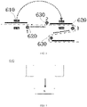
- unwinding and cutting intervals of the positive electrode unwinding mechanism, the negative electrode unwinding mechanism, the positive electrode cutting mechanism, and the negative electrode cutting mechanism can be comprehensively adjusted, in such a manner that a length of the cut positive electrode sheet is smaller than a length of the cut negative electrode sheet, and a horizontal distance d between a positive electrode sheet in a positive electrode lamination unit and a negative electrode sheet in a negative electrode lamination unit adjacent to the positive electrode lamination unit is 1mm to 6 mm (as illustrated in FIG.
- the length of the negative electrode sheet can be 0.5mm to 3 mm smaller than the length of the separator, ensuring higher safety and stability of the electrode assembly. It should be noted that the length described in the present disclosure is defined in terms of a moving direction of the electrode sheets, and can also be understood as the length of a respective side.
- the negative electrode unwinding mechanism 110, the separator unwinding mechanism 120, and the positive electrode unwinding mechanism 130 in the unwinding mechanism 100 may be distributed from top to bottom or from bottom to top.
- FIG. 2 is a schematic diagram illustrating alternated positive electrode lamination unit A and negative electrode lamination unit B when the negative electrode unwinding mechanism 110, the separator unwinding mechanism 120 and the positive electrode unwinding mechanism 130 are distributed from bottom to top.
- the preheating and rolling device 300 includes a preheating apparatus (not individually shown) and a rolling apparatus (not individually shown) that are sequentially connected, the preheating apparatus is arranged between the unwinding mechanism 110 and the rolling apparatus, the rolling apparatus is arranged downstream of the electrode-winding cutting mechanism 200, and the rolling apparatus is configured to enable the positive electrode sheets and the negative electrode sheets of the laminated layer to be respectively adhered to the separator to obtain a laminate including alternately distributed positive electrode lamination units A and negative electrode lamination units B.
- the preheating apparatus can preheat the separator, the positive electrode sheet, and the negative electrode sheet before the electrode sheets are cut, so that the preheating time is longer, and an adhesion effect of the roller-pressed electrode sheets and separator is further improved.
- the positive electrode lamination unit A includes a layer of positive electrode sheet and a layer of separator
- the negative electrode lamination unit B includes a layer of negative electrode sheet and a layer of separator.
- the detection apparatus 400 is arranged downstream of the preheating and rolling device 300, and configured to detect whether the laminate has a defect.
- the detection apparatus 400 can detect a position, a size, a wrinkle, a tab wrinkle, an edge fold, an unfilled corner and the like of the electrode sheets, so that defective lamination units can be discarded in time; further, when the lamination units are under detection with the detection apparatus, there is no need for the lamination units to be transferred, it is no longer necessary to separately and additionally provide a positioning platform and a group of manipulators, and the structure is simpler.
- the detection apparatus 400 may be a CCD detection mechanism.
- the separator cutting mechanism 500 includes a first separator cutting mechanism 510 and a second separator cutting mechanism 520.
- the first separator cutting mechanism 510 is arranged upstream of the second separator cutting mechanism 520, and configured to cut and discharge, based on a detection result of the detection apparatus, a defective positive electrode lamination unit/a defective negative electrode lamination unit and a negative electrode lamination unit/a positive electrode lamination unit adjacent to the defective positive electrode lamination unit/the defective negative electrode lamination unit in pairs.
- the second separator cutting mechanism 520 is configured to perform separator cutting on a last qualified lamination unit based on a number of layers to be laminated.
- the positive electrode lamination unit and the negative electrode lamination unit need to be discharged in pairs, for example, if one positive electrode lamination unit has a defect, one negative electrode lamination unit needs to be discarded at the same time; in addition, the separator between lamination units having no defects is not cut off in the subsequent lamination process, and the separator is cut off by the second separator cutting mechanism only after the lamination is finished, so that the number of times for cutting the separator is very small, and a risk of the separator wrinkling to expose the electrode sheets in the lamination process is greatly reduced.
- the die-cutting lamination system may further include a discharger 800, and the discharger 800 may be arranged downstream of the detection apparatus 400 and configured to cooperate with the first separator cutting mechanism 510 to discharge a defective lamination unit based on the display of the detection apparatus 400.
- the discharger 800 may be an NG discharger.
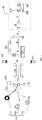
- the lamination apparatus 600 is arranged downstream of the separator cutting mechanism 500 and configured to stack the positive electrode lamination units A and the negative electrode lamination units B alternately, thereby obtaining an electrode assembly including a plurality of layers of positive electrode sheet and a plurality of layers of negative electrode sheet.
- the lamination apparatus 600 may include a clamping jaw 610, a first auxiliary roller 620, and a second auxiliary roller 630, the clamping jaw 610 and the first auxiliary roller 620 are movable and are configured to cooperate with the second auxiliary roller 630 in such a manner that the positive electrode lamination units A and the negative electrode lamination units B are spread, aligned, and alternately stacked.
- the clamping jaw clamps the laminate from upper and lower sides of the lamination units (as illustrated in FIG.
- the clamping jaw can clamp the laminate from an upper side and a lower side that are perpendicular to a moving direction of the electrode sheets), and the first auxiliary roller and the second auxiliary roller cooperate with the clamping jaw to realize the stacking of two adjacent lamination units, and assist in the alignment of the lamination units;
- the position of the second auxiliary roller is relatively fixed and can be finely adjusted, and the tension of the lamination units is controlled by adjusting the first auxiliary roller and the second auxiliary roller, so that the lamination units are alternately stacked and aligned;
- the lamination manner of the present disclosure using the cooperation of the clamping jaw with the auxiliary rollers is a horizontal lamination manner, which is not only more conducive to lamination alignment and but also allows a smaller space occupancy rate of the system in the vertical direction, compared with a vertical lamination manner;
- the clamping jaw is adopted to replace a negative pressure manipulator to realize the transfer of lamination units, which can effectively avoid a risk of dropping of a lower electrode sheet/a
- the lamination apparatus 600 includes two sets of the first auxiliary roller 620 and the second auxiliary roller 630.
- One set is in an operating state in which the auxiliary rollers cooperate with the clamping jaw to stack and align two adjacent lamination units, the other set is in a ready state for stacking and aligning a next pair of lamination units, and after the two adjacent lamination units are stacked and aligned, the auxiliary rollers in the operating state are withdrawn and enter the ready state.
- the auxiliary rollers in the operating state are withdrawn and enter the ready state.
- the auxiliary rollers are in the ready state, the first auxiliary roller 620 is located at position 1, and the second auxiliary roller 630 is located at position 2; when the clamping jaw 610 clamps a lamination unit and transfers the lamination unit to the lamination position, the set of auxiliary rollers is put into operation, the first auxiliary roller 620 is transferred to position 3, the position of the second auxiliary roller is basically unchanged, and the second auxiliary roller is only finely adjusted at the original position to aid in aligning the lamination unit, and at this time, the other set of auxiliary rollers is let ready at position 1 and position 2.
- the negative electrode unwinding mechanism 110, the separator unwinding mechanism 120, and the positive electrode unwinding mechanism 130 in the unwinding mechanism 100 are distributed from top to bottom, the negative electrode sheet is positioned above the separator, the positive electrode sheet is positioned below the separator, a plurality of negative electrode lamination units and a plurality of positive electrode lamination units are alternately pre-stacked, and then one layer of separator is stacked.
- the positive electrode sheet is positioned above the separator, the negative electrode sheet is positioned below the separator, one layer of separator is pre-stacked, and then a plurality of positive electrode lamination units and a plurality of negative electrode lamination units are alternately stacked.
- the negative electrode lamination unit includes a layer of negative electrode sheet and a layer of separator.
- a first layer of electrode sheet in each electrode assembly is a negative electrode sheet.
- the negative electrode unwinding mechanism 110, the separator unwinding mechanism 120, and the positive electrode unwinding mechanism 130 are distributed from top to bottom, and assuming that the electrode assembly has N layers (N is an odd number), including (N-1)/2 layers of positive electrode and (N+1)/2 layers of negative electrode, the positive electrode unwinding mechanism stops the unwinding operation when the ((N+1)/2) th layer of negative electrode sheet is cut, in such a manner that a separate segment of separator is reserved between the ((N+1)/2) th negative electrode sheet and the ((N+1)/2+1) th negative electrode sheet, and the positive electrode unwinding mechanism continues the unwinding operation after the ((N+1)/2+1) th negative electrode sheet is cut.
- the second separator cutting mechanism cuts the separator, and the cutting position of the separator is at the right side of the ((N + 1)/2 +1) th negative electrode sheet and is 0.5mm to 3 mm away from the rightmost end of this electrode sheet. After the cutting, the reserved last layer of separator is covered on the last negative electrode sheet. Then a fixing adhesive tape is affixed, and finally blanking is performed.
- the die-cutting lamination system of the present disclosure has the following advantages: (1) according to the present disclosure, the die-cutting apparatus and the lamination apparatus are integrated in the die-cutting lamination system, on the one hand, a feeding cartridge is omitted, and a limitation of feeding with the cartridge is broken through, on the other hand, the electrode sheets are adhered to the separator through preheating and roller pressing, and the lamination feed is a roll material instead of a single sheet feed, which can break through a limitation of the mechanical structure and increase the lamination speed; (2) the number of lamination machines can be greatly reduced, the feeding can be conducted continuously, the acquisition cost of the devices is reduced, the energy consumption of the device is reduced, and a theoretical lamination speed can reach 0.25s/sheet to 0.6s/sheet; (3) an edge shape of the separator after the separator is cut cannot be ensured and a risk of the separator wrinkling to expose the electrode sheets exists in the lamination process; instead, the separator between lamination units containing no defect is not cut during the lamination
- the present disclosure provides a die-cutting lamination method using the die-cutting lamination system.
- the method includes: (1) providing, by the unwinding mechanisms, electrode sheets and a separator, enabling the negative electrode cutting mechanism to cooperate with the negative electrode unwinding mechanism and cut negative electrode sheets, and enabling the positive electrode cutting mechanism to cooperate with the positive electrode unwinding mechanism and cut positive electrode sheets, to obtain a laminated layer including the separator, the negative electrode sheets, and the positive electrode sheets, the negative electrode sheets and the positive electrode sheets being alternately distributed on an upper side and a lower side of the separator; (2) preheating, by the preheating apparatus, the separator, and the positive electrode sheets and the negative electrode sheets before and after cutting, and roller pressing, by the rolling apparatus, the laminated layer to respectively adhere the positive electrode sheets and the negative electrode sheets of the laminated layer to the separator to obtain a laminate including alternately distributed positive electrode lamination units and negative electrode lamination
- the lamination units may be stacked by the clamping jaw, the first auxiliary roller, and the second auxiliary roller in cooperation to obtain the electrode assembly in which positive electrode lamination units and negative electrode lamination units are spread, aligned, and alternately stacked.
- the lamination manner is a horizontal lamination manner, and compared with the vertical lamination manner, the horizontal lamination manner is more favorable for the alignment of the lamination and the system occupies smaller space in the vertical direction; further, according to the present disclosure, the clamping jaw is adopted to replace the negative pressure manipulator to realize the transfer of lamination units, which can effectively avoid a risk of dropping of a lower electrode sheet/separator of a lamination unit when sucking an upper side of the lamination unit to transfer the lamination unit.
- a length of each positive electrode sheet in the finally obtained electrode assembly is smaller than a length of each negative electrode sheet in the finally obtained electrode assembly, and the length of each negative electrode sheet in the finally obtained electrode assembly may be 0.5mm to 3mm smaller than a length of each separator in the finally obtained electrode assembly. The risk of exposing the electrode sheets can thereby be avoided.
- a plurality of negative electrode lamination units and a plurality of positive electrode lamination units are alternately pre-stacked, and then a layer of separator is stacked; when the positive electrode sheet is positioned above the separator and the negative electrode sheet is positioned below the separator, a layer of separator is pre-stacked, and then a plurality of positive electrode lamination units and a plurality of negative electrode lamination units are alternately stacked.
- the die-cutting lamination method of the present disclosure has the following advantages.
- (1) the electrode sheet cutting and lamination are coupled together, on the one hand, a feeding cartridge is omitted, and a limitation of feeding with the cartridge is broken through, on the other hand, the electrode sheets are adhered to the separator through preheating and roller pressing to form the lamination units, the lamination feed is a roll material instead of a single sheet feed, and continuous feeding can be achieved, which can break through a limitation of the mechanical structure, and increase the lamination speed;
- the electrode sheets and the separator are laminated synchronously, the lamination speed is fast, and a theoretical lamination speed can reach 0.25s/sheet to 0.6s/sheet; (3) a number of cuttings of the separator is very small, which greatly reduces a risk of the separator wrinkling to expose the electrode sheets; (4) compared with a manner that each lamination unit is cut off separately and then detected and laminated, there is no need to transfer lamination units during detection of the lamination units
Landscapes
- Chemical & Material Sciences (AREA)
- Chemical Kinetics & Catalysis (AREA)
- Electrochemistry (AREA)
- General Chemical & Material Sciences (AREA)
- Engineering & Computer Science (AREA)
- Manufacturing & Machinery (AREA)
- Secondary Cells (AREA)
Applications Claiming Priority (2)
| Application Number | Priority Date | Filing Date | Title |
|---|---|---|---|
| CN201910642631.6A CN110364766B (zh) | 2019-07-16 | 2019-07-16 | 模切叠片系统及方法 |
| PCT/CN2020/102124 WO2021008553A1 (fr) | 2019-07-16 | 2020-07-15 | Système et procédé de découpe et de stratification |
Publications (2)
| Publication Number | Publication Date |
|---|---|
| EP4002542A1 true EP4002542A1 (fr) | 2022-05-25 |
| EP4002542A4 EP4002542A4 (fr) | 2023-08-16 |
Family
ID=68219735
Family Applications (1)
| Application Number | Title | Priority Date | Filing Date |
|---|---|---|---|
| EP20840055.6A Pending EP4002542A4 (fr) | 2019-07-16 | 2020-07-15 | Système et procédé de découpe et de stratification |
Country Status (4)
| Country | Link |
|---|---|
| EP (1) | EP4002542A4 (fr) |
| KR (1) | KR20220035211A (fr) |
| CN (1) | CN110364766B (fr) |
| WO (1) | WO2021008553A1 (fr) |
Cited By (1)
| Publication number | Priority date | Publication date | Assignee | Title |
|---|---|---|---|---|
| DE102022208588A1 (de) | 2022-08-18 | 2024-02-29 | Volkswagen Aktiengesellschaft | Verfahren zur Herstellung einer Elektroden-Separator-Einrichtung |
Families Citing this family (14)
| Publication number | Priority date | Publication date | Assignee | Title |
|---|---|---|---|---|
| CN110364766B (zh) * | 2019-07-16 | 2022-06-21 | 蜂巢能源科技有限公司 | 模切叠片系统及方法 |
| CN110911646B (zh) * | 2019-10-25 | 2022-05-10 | 合肥国轩高科动力能源有限公司 | 一种复合集流体滚焊模切一体化设备及滚焊模切方法 |
| CN112259804A (zh) * | 2020-03-31 | 2021-01-22 | 蜂巢能源科技有限公司 | 极组的叠片方法以及极组的叠片设备 |
| CN111430770A (zh) * | 2020-03-31 | 2020-07-17 | 蜂巢能源科技有限公司 | 模切叠片加工装置 |
| CN111883852B (zh) * | 2020-05-28 | 2021-06-11 | 合肥国轩高科动力能源有限公司 | 一种四卷芯的成型方法 |
| CN112234257A (zh) * | 2020-09-24 | 2021-01-15 | 江苏中关村嘉拓新能源设备有限公司 | 一种热复合电芯制备方法及系统 |
| CN112635700B (zh) * | 2020-12-18 | 2022-04-01 | 蜂巢能源科技有限公司 | 一种电池极组制备装置、电池极组制备方法及电池极组 |
| CN113839101B (zh) * | 2021-09-03 | 2023-08-29 | 无锡奥特维智能装备有限公司 | 电芯叠片方法 |
| CN114122528B (zh) * | 2021-11-25 | 2023-07-21 | 蜂巢能源科技有限公司 | 极片裁切输送装置及叠片系统 |
| IT202100030239A1 (it) * | 2021-11-30 | 2023-05-30 | P I T S R L | Macchina per la realizzazione di dispositivi di accumulo di energia elettrica |
| CN114709466B (zh) * | 2022-04-07 | 2024-09-06 | 博众精工科技股份有限公司 | 一种贴胶设备 |
| CN114824501B (zh) * | 2022-06-29 | 2022-10-04 | 江苏福瑞士电池科技有限公司 | 一种锂电池用叠片机 |
| CN115839959A (zh) * | 2022-11-03 | 2023-03-24 | 宁德时代新能源科技股份有限公司 | 极耳检测系统及极耳检测方法 |
| CN118248965B (zh) * | 2024-05-28 | 2024-08-27 | 江西和润宇电源科技有限公司 | 一种可调式铅酸蓄电池叠片装置及其叠片方法 |
Family Cites Families (15)
| Publication number | Priority date | Publication date | Assignee | Title |
|---|---|---|---|---|
| JP2000133248A (ja) * | 1998-10-21 | 2000-05-12 | Mitsubishi Chemicals Corp | 薄膜型電池の製造方法 |
| CN1697237A (zh) * | 2004-05-11 | 2005-11-16 | 中国电子科技集团公司第十八研究所 | 一种方形锂离子电池芯及其制造方法 |
| CN104934628B (zh) * | 2015-06-05 | 2020-04-10 | 深圳吉阳智云科技有限公司 | 具有极片和隔膜检测的电芯制备系统及方法 |
| CN105428697B (zh) * | 2015-12-01 | 2018-01-12 | 深圳职业技术学院 | 电池叠片装置及电池叠片方法 |
| WO2018021263A1 (fr) * | 2016-07-28 | 2018-02-01 | 三洋電機株式会社 | Procédé de fabrication de batterie rechargeable |
| CN106025375A (zh) * | 2016-07-30 | 2016-10-12 | 深圳科瑞技术股份有限公司 | 一种锂电池叠片机隔离膜的放卷控制系统 |
| KR102264685B1 (ko) * | 2016-11-30 | 2021-06-15 | (주)엘지에너지솔루션 | 전극조립체 제조장치 및 전극조립체를 제조하는 방법 |
| KR102167118B1 (ko) * | 2017-04-26 | 2020-10-16 | 주식회사 엘지화학 | 이차전지용 라미네이션장치 |
| CN207097976U (zh) * | 2017-08-24 | 2018-03-13 | 雷天温斯顿电池(长泰)有限公司 | 一种锂电池模切叠片一体机 |
| CN109560328A (zh) * | 2017-12-29 | 2019-04-02 | 蜂巢能源科技有限公司 | 电极层叠组件的制造方法以及电极层叠组件 |
| CN208690429U (zh) * | 2017-12-29 | 2019-04-02 | 蜂巢能源科技有限公司 | 电化学装置的电极层叠组件以及电化学装置 |
| CN208655820U (zh) * | 2018-02-01 | 2019-03-26 | 深圳前海优容科技有限公司 | 一种叠片机 |
| CN109244554B (zh) * | 2018-09-21 | 2020-12-29 | 江苏卡耐新能源有限公司 | 一种锂离子电池z字形叠片设备及其工艺 |
| KR102692319B1 (ko) * | 2018-12-06 | 2024-08-07 | 현대자동차주식회사 | 이차전지의 셀 스태킹 장치 및 이차전지의 제조시스템 |
| CN110364766B (zh) * | 2019-07-16 | 2022-06-21 | 蜂巢能源科技有限公司 | 模切叠片系统及方法 |
-
2019
- 2019-07-16 CN CN201910642631.6A patent/CN110364766B/zh active Active
-
2020
- 2020-07-15 WO PCT/CN2020/102124 patent/WO2021008553A1/fr unknown
- 2020-07-15 EP EP20840055.6A patent/EP4002542A4/fr active Pending
- 2020-07-15 KR KR1020227005228A patent/KR20220035211A/ko active IP Right Grant
Cited By (1)
| Publication number | Priority date | Publication date | Assignee | Title |
|---|---|---|---|---|
| DE102022208588A1 (de) | 2022-08-18 | 2024-02-29 | Volkswagen Aktiengesellschaft | Verfahren zur Herstellung einer Elektroden-Separator-Einrichtung |
Also Published As
| Publication number | Publication date |
|---|---|
| WO2021008553A1 (fr) | 2021-01-21 |
| CN110364766A (zh) | 2019-10-22 |
| EP4002542A4 (fr) | 2023-08-16 |
| CN110364766B (zh) | 2022-06-21 |
| KR20220035211A (ko) | 2022-03-21 |
Similar Documents
| Publication | Publication Date | Title |
|---|---|---|
| EP4002541A1 (fr) | Système et procédé de stratification par matriçage | |
| EP4002542A1 (fr) | Système et procédé de découpe et de stratification | |
| WO2021008554A1 (fr) | Système et procédé de stratification par découpe | |
| EP4012815B1 (fr) | Appareil intégré pour découpage à l'emporte-pièce et empilement de feuilles | |
| TWI472080B (zh) | A position detecting device and a position detecting method | |
| WO2022179621A1 (fr) | Élément de batterie et appareil de stratification | |
| KR101291063B1 (ko) | 2차 전지 내부 셀 스택 적층 장치 및 방법 | |
| CN111342107A (zh) | 一种热复合高速叠片机 | |
| US20230148346A1 (en) | Apparatus and Method for Manufacturing Unit Cells | |
| CN114464865A (zh) | 一种叠片电芯制备方法、装置及叠片电芯 | |
| CN114122527A (zh) | 一种电芯循环供外板叠片生产线及其生产工艺 | |
| CN211700479U (zh) | 一种热复合高速叠片机 | |
| KR102515416B1 (ko) | 이차전지 제조 장치 | |
| KR20220109202A (ko) | 분리막 접착장치 | |
| CN210296524U (zh) | 叠片机 | |
| CN217881611U (zh) | 一种叠片生产线 | |
| CN115036556A (zh) | 一种叠片装置及叠片生产线 | |
| WO2023184674A1 (fr) | Machine d'empilage de stratification à grande vitesse pour cellule stratifiée, et procédé d'empilement de stratification | |
| CN216698456U (zh) | 叠片设备 | |
| CN209515902U (zh) | 一种复合式叠片系统 | |
| CN217691274U (zh) | 一种叠片生产线 | |
| CN217667198U (zh) | 一种极片裁切输送装置、设备及叠片机 | |
| CN116632317B (zh) | 电芯卷绕设备及电芯卷绕方法 | |
| CN212366028U (zh) | 一种电芯正负极片对贴设备 | |
| CN217691263U (zh) | 叠片装置及具有其的电池生产线 |
Legal Events
| Date | Code | Title | Description |
|---|---|---|---|
| STAA | Information on the status of an ep patent application or granted ep patent |
Free format text: STATUS: THE INTERNATIONAL PUBLICATION HAS BEEN MADE |
|
| PUAI | Public reference made under article 153(3) epc to a published international application that has entered the european phase |
Free format text: ORIGINAL CODE: 0009012 |
|
| STAA | Information on the status of an ep patent application or granted ep patent |
Free format text: STATUS: REQUEST FOR EXAMINATION WAS MADE |
|
| 17P | Request for examination filed |
Effective date: 20220215 |
|
| AK | Designated contracting states |
Kind code of ref document: A1 Designated state(s): AL AT BE BG CH CY CZ DE DK EE ES FI FR GB GR HR HU IE IS IT LI LT LU LV MC MK MT NL NO PL PT RO RS SE SI SK SM TR |
|
| DAV | Request for validation of the european patent (deleted) | ||
| DAX | Request for extension of the european patent (deleted) | ||
| A4 | Supplementary search report drawn up and despatched |
Effective date: 20230719 |
|
| RIC1 | Information provided on ipc code assigned before grant |
Ipc: H01M 10/0583 20100101AFI20230713BHEP |
|
| RIN1 | Information on inventor provided before grant (corrected) |
Inventor name: WANG, YANG Inventor name: KIM, JEONG HYUN Inventor name: TENG, LIJIE Inventor name: XU, CHUNLONG Inventor name: ZHAO, KAI Inventor name: JEONG, HYEOK Inventor name: KIM, SEONG JU |