EP4001982B1 - Faseroptisches schutzsystem - Google Patents
Faseroptisches schutzsystem Download PDFInfo
- Publication number
- EP4001982B1 EP4001982B1 EP21183955.0A EP21183955A EP4001982B1 EP 4001982 B1 EP4001982 B1 EP 4001982B1 EP 21183955 A EP21183955 A EP 21183955A EP 4001982 B1 EP4001982 B1 EP 4001982B1
- Authority
- EP
- European Patent Office
- Prior art keywords
- optical fiber
- protection circuit
- protection system
- heat shrink
- protection
- Prior art date
- Legal status (The legal status is an assumption and is not a legal conclusion. Google has not performed a legal analysis and makes no representation as to the accuracy of the status listed.)
- Active
Links
Images
Classifications
-
- G—PHYSICS
- G02—OPTICS
- G02B—OPTICAL ELEMENTS, SYSTEMS OR APPARATUS
- G02B6/00—Light guides; Structural details of arrangements comprising light guides and other optical elements, e.g. couplings
- G02B6/44—Mechanical structures for providing tensile strength and external protection for fibres, e.g. optical transmission cables
- G02B6/4479—Manufacturing methods of optical cables
- G02B6/4486—Protective covering
-
- G—PHYSICS
- G01—MEASURING; TESTING
- G01K—MEASURING TEMPERATURE; MEASURING QUANTITY OF HEAT; THERMALLY-SENSITIVE ELEMENTS NOT OTHERWISE PROVIDED FOR
- G01K11/00—Measuring temperature based upon physical or chemical changes not covered by groups G01K3/00, G01K5/00, G01K7/00 or G01K9/00
- G01K11/06—Measuring temperature based upon physical or chemical changes not covered by groups G01K3/00, G01K5/00, G01K7/00 or G01K9/00 using melting, freezing, or softening
-
- G—PHYSICS
- G01—MEASURING; TESTING
- G01K—MEASURING TEMPERATURE; MEASURING QUANTITY OF HEAT; THERMALLY-SENSITIVE ELEMENTS NOT OTHERWISE PROVIDED FOR
- G01K3/00—Thermometers giving results other than momentary value of temperature
- G01K3/005—Circuits arrangements for indicating a predetermined temperature
-
- G—PHYSICS
- G01—MEASURING; TESTING
- G01K—MEASURING TEMPERATURE; MEASURING QUANTITY OF HEAT; THERMALLY-SENSITIVE ELEMENTS NOT OTHERWISE PROVIDED FOR
- G01K7/00—Measuring temperature based on the use of electric or magnetic elements directly sensitive to heat ; Power supply therefor, e.g. using thermoelectric elements
- G01K7/16—Measuring temperature based on the use of electric or magnetic elements directly sensitive to heat ; Power supply therefor, e.g. using thermoelectric elements using resistive elements
-
- G—PHYSICS
- G01—MEASURING; TESTING
- G01R—MEASURING ELECTRIC VARIABLES; MEASURING MAGNETIC VARIABLES
- G01R31/00—Arrangements for testing electric properties; Arrangements for locating electric faults; Arrangements for electrical testing characterised by what is being tested not provided for elsewhere
- G01R31/327—Testing of circuit interrupters, switches or circuit-breakers
-
- G—PHYSICS
- G02—OPTICS
- G02B—OPTICAL ELEMENTS, SYSTEMS OR APPARATUS
- G02B6/00—Light guides; Structural details of arrangements comprising light guides and other optical elements, e.g. couplings
- G02B6/44—Mechanical structures for providing tensile strength and external protection for fibres, e.g. optical transmission cables
- G02B6/4401—Optical cables
- G02B6/4429—Means specially adapted for strengthening or protecting the cables
- G02B6/443—Protective covering
-
- H—ELECTRICITY
- H05—ELECTRIC TECHNIQUES NOT OTHERWISE PROVIDED FOR
- H05B—ELECTRIC HEATING; ELECTRIC LIGHT SOURCES NOT OTHERWISE PROVIDED FOR; CIRCUIT ARRANGEMENTS FOR ELECTRIC LIGHT SOURCES, IN GENERAL
- H05B47/00—Circuit arrangements for operating light sources in general, i.e. where the type of light source is not relevant
- H05B47/10—Controlling the light source
- H05B47/105—Controlling the light source in response to determined parameters
Definitions
- the present invention relates to an optical fiber protection system.
- the light transmission property and the flexible property of the optical fiber make the projection system more flexible.
- the projection system includes an imaging system and a light source system that are isolated from each other, and the optical fiber may be connected with the imaging system and the light source system that are isolated from each other so as to transmit the light.
- the light transmission efficiency of the optical fiber may degrade due to improper usage, such that the temperature of the optical fiber is increased. Therefore, the inner part of the melted optical fiber may be broken due to high temperature or the outer shell of the melted optical fiber may be penetrated such that the light may transmit out of the optical fiber and damage may occur.
- US 2009/296018 A1 discloses an optical fiber protection system having an optical fiber, a light source for transmitting a signal to the optical fiber, a protection circuit, and a sensor electrically connected to the protection circuit.
- the present invention provides an optical fiber protection system according to claim 1.
- a material of the protection circuit includes a low-temperature solder.
- the optical fiber protection system includes a heat shrink tubing surrounds the low-temperature solder and the optical fiber, and the low-temperature solder is located between the heat shrink tubing and the optical fiber.
- a shrink temperature of the heat shrink tubing is higher than a melting temperature of the low-temperature solder.
- a portion of the protection circuit is exposed form the heat shrink tubing.
- the sensor is configured to determine whether the protection circuit is an open circuit.
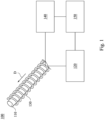
- Fig. 1 is a schematic of an optical fiber protection system 100 of an embodiment of the present disclosure.
- the optical fiber protection system 100 includes an optical fiber 110, a light source 120, a protection circuit 130, a sensor 140, and a controller 150.
- the light source 120 is configured to transmit a signal to the optical fiber 110.
- the protection circuit 130 extends along a length direction D of the optical fiber 110.
- the sensor 140 is electrically connected to the protection circuit 130.
- the controller 150 is electrically connected to the sensor 140 and the light source 120.
- a material of the protection circuit 130 includes a low-temperature solder.
- the materials of the low-temperature solder include an alloy of Bi, Pb, and Sn, and a melting temperature of the low-temperature solder is in a range of about 90 degrees to 100 degrees, but the present disclosure is not limited in this regard. Person having ordinary skill in the art may choose materials with specific melting points.
- the sensor 140 is configured to determine whether the protection circuit 130 is an open circuit.
- the controller 150 is configured to control the light source 120 based on a sensing result of the sensor 140. As such, when the optical fiber 110 is partially overheated, the property of the low-temperature solder of the protection circuit 130 may form an open circuit, and the sensor 140 may sense that whether the protection circuit 130 is an open circuit. Subsequently, the controller 150 may transmit the signal to the light source 120 so as to shut down the power to protect the optical fiber 110.
- the optical fiber protection system 110 of the present disclosure may be applied for a projection system.
- the projection system includes isolated imaging system and the light source system, and the optical fiber 110 may connected with the imaging system and the light source system that are isolated with each other so as to transmit the light.
- the inner part of the melted optical fiber 110 may be broken due to high temperature or the outer shell of the melted optical fiber 110 may be penetrated such that the light may transmit out of the optical fiber 110. Therefore, by disposing the optical protection system 110 in the projection system, the life time of the projection system may be prolonged and the application flexibility of the projection system with the imaging system and the light source system that are isolated with each other may be increased.
- the protection circuit 130 twines around the optical fiber 110 in spiral shape, but the present disclosure is not limited in this regard.
- the protection circuit 130 may be disposed on the optical fiber 110 in parallel as long as the protection circuit 130 can be in contact with the optical fiber 110 and absorb the heat of the optical fiber 110 to form the open circuit.
- the protection circuit 130 twines around the optical fiber 110 can be bent easily along with the optical fiber 110, thereby reducing the possibility of broken of the protection circuit 130.
- the protection circuit 130 can be attached on the optical fiber 110 better.
- the senor 140 is configured to sense an electrical resistance of the protection circuit 130.
- the controller 150 may determine whether the power will be applied continuously or not based on the measured variation of the electrical resistance of the protection circuit 130 and the predetermined threshold of the electrical resistance.
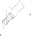
- Fig. 2 is a schematic of an optical fiber protection 200 system of another embodiment of the present disclosure.
- the light source 120, the sensor 140, and the controller 150 of the optical fiber protection 200 are omitted in Fig. 2 .
- the optical fiber protection 200 is substantially the same as the optical fiber protection 100, and the difference is that the optical fiber protection 200 further includes a heat shrink tubing 132.
- the heat shrink tubing 132 at least partially surrounds the protection circuit 130 and the optical fiber 110.
- the protection circuit 130 is located between the heat shrink tubing 132 and the optical fiber 110.
- a length of the heat shrink tubing 132 is smaller than a length of the optical fiber 110. That is, two sides of the optical fiber 110 protrude from the heat shrink tubing 132.
- a portion of the protection circuit 130 is exposed form the heat shrink tubing 132.
- the length of the protection circuit 130 that is twined may be adjusted according to practical requirements.
- the range of the heat shrink tubing 132 that is wrapped may be adjusted according to practical requirements.
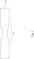
- Fig. 3 is a schematic of the optical fiber protection system shown in Fig. 2 , wherein the optical fiber protection system is overheated.
- the material of the heat shrink tubing 132 may be Polyethylene (PE), and the shrink temperature of the heat shrink tubing 132 is of about 105 degrees to 115 degrees.
- a shrink temperature of the heat shrink tubing 132 is higher than a melting temperature of the low-temperature solder.
- the heat shrink tubing 132 may shrink to push the melted low-temperature solder due to high temperature when the optical fiber 110 is partially overheated such that the protection circuit 130 may form the open circuit and the insulating property at the melting position may be increased. Therefore, the precision of the optical fiber protection system 200 may be improved by using the low-temperature solder and the heat shrink tubing 132.
- the property of the low-temperature solder of the protection circuit 130 may be utilized to form an open circuit of the optical fiber protection system of the present disclosure, and the sensor 140 may sense that whether the protection circuit 130 is an open circuit. Subsequently, the controller 150 may transmit the signal to the light source 120 so as to shut down the power to protect the optical fiber 110. Or, the heat shrink tubing 132 may shrink to push the melted low-temperature solder due to high temperature such that the protection circuit 130 may form the open circuit and the insulating property at the melting position may be increased to improve the precision of the optical fiber protection system.
Landscapes
- Physics & Mathematics (AREA)
- General Physics & Mathematics (AREA)
- Optics & Photonics (AREA)
- Engineering & Computer Science (AREA)
- Manufacturing & Machinery (AREA)
- Optical Couplings Of Light Guides (AREA)
- Measuring Temperature Or Quantity Of Heat (AREA)
- Geophysics And Detection Of Objects (AREA)
Claims (9)
- Schutzsystem (100) für optische Fasern, das Folgendes umfasst:eine optische Faser (110);eine Lichtquelle (120), die so konfiguriert ist, dass sie ein Signal an die optische Faser (110) überträgt; undeine Schutzschaltung (130), die sich entlang einer Längsrichtung (D) der optischen Faser (110) erstreckt;einen Sensor (140), der mit der Schutzschaltung (130) elektrisch verbunden ist, wobei der Sensor (140) so konfiguriert ist, dass er einen elektrischen Widerstand der Schutzschaltung (130) erfasst; undeine Steuerung (150), die mit dem Sensor (140) und der Lichtquelle (120) elektrisch verbunden ist.
- Faserschutzsystem (100) nach Anspruch 1, wobei sich die Schutzschaltung (130) um die optische Faser (110) windet.
- Faserschutzsystem (100) nach einem der Ansprüche 1-2, wobei ein Material der Schutzschaltung (130) ein Niedrigtemperaturlot enthält.
- Faserschutzsystem (100) nach Anspruch 3, das Folgendes umfasst:
einen Schrumpfschlauch (132), der das Niedrigtemperaturlot und die optische Faser (110) umgibt, und wobei das Niedrigtemperaturlot zwischen dem Schrumpfschlauch (132) und der optischen Faser (110) angeordnet ist. - Faserschutzsystem (100) nach Anspruch 4, wobei eine Schrumpftemperatur des Schrumpfschlauchs (132) höher als eine Schmelztemperatur des Niedrigtemperaturlots ist.
- Faserschutzsystem (100) nach einem der Ansprüche 4-5, wobei eine Länge des Schrumpfschlauchs (132) kleiner als eine Länge der optischen Faser (110) ist und zwei Seiten der optischen Faser (110) aus dem Schrumpfschlauch (132) herausragen.
- Faserschutzsystem (100) nach einem der Ansprüche 4-6, wobei ein Teil der Schutzschaltung (130) von dem Schrumpfschlauch (132) freiliegt.
- Faserschutzsystem (100) nach einem der Ansprüche 1-7, wobei der (140) Sensor so konfiguriert ist, dass er bestimmt, ob die Schutzschaltung (130) eine offene Schaltung ist.
- Faserschutzsystem (100) nach einem der Ansprüche 1-8, wobei die Steuerung (150) so konfiguriert ist, dass sie die Lichtquelle (120) basierend auf einem Erfassungsergebnis des Sensors steuert.
Priority Applications (1)
| Application Number | Priority Date | Filing Date | Title |
|---|---|---|---|
| EP24174564.5A EP4407229A3 (de) | 2020-11-24 | 2021-07-06 | Glasfaserschutzsystem und betriebsverfahren dafür |
Applications Claiming Priority (1)
| Application Number | Priority Date | Filing Date | Title |
|---|---|---|---|
| CN202011327855.7A CN114545574A (zh) | 2020-11-24 | 2020-11-24 | 光纤保护系统 |
Related Child Applications (2)
| Application Number | Title | Priority Date | Filing Date |
|---|---|---|---|
| EP24174564.5A Division-Into EP4407229A3 (de) | 2020-11-24 | 2021-07-06 | Glasfaserschutzsystem und betriebsverfahren dafür |
| EP24174564.5A Division EP4407229A3 (de) | 2020-11-24 | 2021-07-06 | Glasfaserschutzsystem und betriebsverfahren dafür |
Publications (3)
| Publication Number | Publication Date |
|---|---|
| EP4001982A1 EP4001982A1 (de) | 2022-05-25 |
| EP4001982B1 true EP4001982B1 (de) | 2024-07-03 |
| EP4001982C0 EP4001982C0 (de) | 2024-07-03 |
Family
ID=76829310
Family Applications (2)
| Application Number | Title | Priority Date | Filing Date |
|---|---|---|---|
| EP21183955.0A Active EP4001982B1 (de) | 2020-11-24 | 2021-07-06 | Faseroptisches schutzsystem |
| EP24174564.5A Pending EP4407229A3 (de) | 2020-11-24 | 2021-07-06 | Glasfaserschutzsystem und betriebsverfahren dafür |
Family Applications After (1)
| Application Number | Title | Priority Date | Filing Date |
|---|---|---|---|
| EP24174564.5A Pending EP4407229A3 (de) | 2020-11-24 | 2021-07-06 | Glasfaserschutzsystem und betriebsverfahren dafür |
Country Status (3)
| Country | Link |
|---|---|
| US (1) | US11703650B2 (de) |
| EP (2) | EP4001982B1 (de) |
| CN (1) | CN114545574A (de) |
Families Citing this family (2)
| Publication number | Priority date | Publication date | Assignee | Title |
|---|---|---|---|---|
| DE102024123043A1 (de) * | 2024-08-13 | 2026-02-19 | Bayerische Motoren Werke Aktiengesellschaft | Lichtleitvorrichtung für einen optischen Sensor eines Fahrzeugs umfassend eine Auswerteeinheit zum Erkennen einer Beschädigung eines Lichtwellenleiters, Sensoranordnung sowie Fahrzeug |
| CN119791829B (zh) * | 2025-01-17 | 2025-10-31 | 天津大学 | 一种可实时控温过热保护的止血装置 |
Family Cites Families (23)
| Publication number | Priority date | Publication date | Assignee | Title |
|---|---|---|---|---|
| US4540601A (en) * | 1984-07-31 | 1985-09-10 | Aetna Telecommunications Laboratories | Aluminum oxide optical fiber coating |
| US5731051A (en) | 1995-09-26 | 1998-03-24 | Minnesota Mining And Manufacturing Company | Fiber optic fusion splice protection sleeve |
| US5712934A (en) * | 1996-07-25 | 1998-01-27 | Johnson; Douglas M. | Fiber optic infrared sensor |
| JP4408589B2 (ja) * | 2001-05-24 | 2010-02-03 | 芝浦メカトロニクス株式会社 | 光ファイバおよびそれを備えたレーザ装置 |
| JP2003279444A (ja) * | 2002-03-26 | 2003-10-02 | Mitsubishi Cable Ind Ltd | 光ファイバ損傷検知装置及びこれを備えたレーザ伝送装置 |
| US6928202B2 (en) * | 2002-10-21 | 2005-08-09 | Virgina Tech Intellectual Properties, Inc. | Method and apparatus for packaging optical fiber sensors for harsh environments |
| JP2004219244A (ja) * | 2003-01-15 | 2004-08-05 | Mitsubishi Cable Ind Ltd | 光ファイバ異常検知装置及びこれを用いたレーザ伝送装置 |
| CN2769904Y (zh) | 2005-03-03 | 2006-04-05 | 北京光电技术研究所 | 激光光纤保护结构 |
| JP2007240258A (ja) * | 2006-03-07 | 2007-09-20 | Shibaura Mechatronics Corp | デリバリファイバ破断検知システム |
| DE102006029203B9 (de) | 2006-06-26 | 2023-06-22 | OSRAM Opto Semiconductors Gesellschaft mit beschränkter Haftung | Lichtemittierende Vorrichtung |
| US8306373B2 (en) * | 2009-05-15 | 2012-11-06 | General Electric Company | Fiber Bragg grating sensing package and system for gas turbine temperature measurement |
| CN102354589B (zh) * | 2011-10-31 | 2013-09-04 | 大连联合高分子材料有限公司 | 一种热缩电线、电缆外绝缘破损快速修补片 |
| TWI506313B (zh) * | 2011-12-27 | 2015-11-01 | Hon Hai Prec Ind Co Ltd | 光纖耦合連接裝置 |
| US9549666B2 (en) * | 2012-11-10 | 2017-01-24 | Curvo Medical, Inc. | Coaxial micro-endoscope |
| KR102192478B1 (ko) * | 2013-02-01 | 2020-12-17 | 데카 프로덕츠 리미티드 파트너쉽 | 패닝가능한 카메라를 구비한 내시경 |
| CN105116483A (zh) | 2015-08-20 | 2015-12-02 | 厦门市和奕华光电科技有限公司 | 光纤熔断保护系统及方法 |
| CN105223643A (zh) * | 2015-10-30 | 2016-01-06 | 厦门市和奕华光电科技有限公司 | 光纤熔断保护系统及方法 |
| CN106019481A (zh) * | 2016-08-03 | 2016-10-12 | 叶穗芳 | 光缆熔接接头合金保护器 |
| WO2018057924A1 (en) * | 2016-09-23 | 2018-03-29 | Canon U.S.A. Inc. | Spectrally encoded endoscopy apparatus and methods |
| CN108233282A (zh) * | 2018-01-17 | 2018-06-29 | 长园电力技术有限公司 | 一种电力电缆现场熔接型包带式直通接头工艺 |
| US11213191B2 (en) * | 2018-01-25 | 2022-01-04 | Canon U.S.A., Inc. | Optical fiber arrangement for endoscope |
| WO2020171059A1 (ja) * | 2019-02-21 | 2020-08-27 | 株式会社フジクラ | 光ファイバケーブル、光ファイバケーブルを用いた光コンバイナユニット、及び、レーザ装置 |
| US11987518B2 (en) * | 2020-06-12 | 2024-05-21 | Corning Incorporated | Methods and systems for cooling optical fiber |
-
2020
- 2020-11-24 CN CN202011327855.7A patent/CN114545574A/zh active Pending
-
2021
- 2021-05-31 US US17/335,025 patent/US11703650B2/en active Active
- 2021-07-06 EP EP21183955.0A patent/EP4001982B1/de active Active
- 2021-07-06 EP EP24174564.5A patent/EP4407229A3/de active Pending
Also Published As
| Publication number | Publication date |
|---|---|
| EP4001982A1 (de) | 2022-05-25 |
| EP4407229A2 (de) | 2024-07-31 |
| EP4001982C0 (de) | 2024-07-03 |
| US11703650B2 (en) | 2023-07-18 |
| CN114545574A (zh) | 2022-05-27 |
| EP4407229A3 (de) | 2024-10-30 |
| US20220163743A1 (en) | 2022-05-26 |
Similar Documents
| Publication | Publication Date | Title |
|---|---|---|
| KR102679724B1 (ko) | 카메라 모듈용 박막 히터 및 이를 갖는 카메라 모듈 | |
| EP4001982B1 (de) | Faseroptisches schutzsystem | |
| KR100295967B1 (ko) | 전기모터보호용센서 | |
| US10902977B2 (en) | Cable assembly | |
| US2413125A (en) | Fire detector cable | |
| US8749341B2 (en) | External operation thermal protector | |
| US20150364286A1 (en) | Complex protection device | |
| US10830648B2 (en) | Abnormal temperature detection system, abnormal temperature detection cable and cable | |
| US8643462B2 (en) | Switch module | |
| TW202211262A (zh) | 多芯纜線 | |
| US4677412A (en) | Energy supplemented electrical fuse | |
| CN104882342A (zh) | 复合保护装置 | |
| US4891500A (en) | Self-healing parallel heating tape | |
| EP3528349B1 (de) | Elektrischer steckverbinder | |
| US20150249333A1 (en) | Complex protection device of blocking the abnormal state of current and voltage | |
| EP1367240A2 (de) | Automatisches Schutzsystem für eine Brennkraftmaschine bei überhitzten elektronischen Bauteilen einer Steueranordnung | |
| TWI763138B (zh) | 光纖保護系統 | |
| JP2003279444A (ja) | 光ファイバ損傷検知装置及びこれを備えたレーザ伝送装置 | |
| KR20130072282A (ko) | 센터링된 감열선 기반의 과열보호 기능을 갖는 고주파 파워 케이블 및 이를 구비한 과열보호 장치 | |
| JP4641744B2 (ja) | パック電池、パック電池に用いる感熱体及び感熱体 | |
| US6601401B2 (en) | Temperature controller and light-waveguide with the same | |
| EP3776603B1 (de) | Wärmgeschütze varistorelement | |
| JP7634040B2 (ja) | 光学的に動作する温度センサ、当該温度センサの使用法、及び少なくとも1つの温度センサを備える電池セル組立体 | |
| JP6201070B1 (ja) | 冷却管内蔵電力線の製造方法 | |
| GB2028608A (en) | Heating circuits |
Legal Events
| Date | Code | Title | Description |
|---|---|---|---|
| PUAI | Public reference made under article 153(3) epc to a published international application that has entered the european phase |
Free format text: ORIGINAL CODE: 0009012 |
|
| STAA | Information on the status of an ep patent application or granted ep patent |
Free format text: STATUS: THE APPLICATION HAS BEEN PUBLISHED |
|
| AK | Designated contracting states |
Kind code of ref document: A1 Designated state(s): AL AT BE BG CH CY CZ DE DK EE ES FI FR GB GR HR HU IE IS IT LI LT LU LV MC MK MT NL NO PL PT RO RS SE SI SK SM TR |
|
| STAA | Information on the status of an ep patent application or granted ep patent |
Free format text: STATUS: REQUEST FOR EXAMINATION WAS MADE |
|
| 17P | Request for examination filed |
Effective date: 20220722 |
|
| RBV | Designated contracting states (corrected) |
Designated state(s): AL AT BE BG CH CY CZ DE DK EE ES FI FR GB GR HR HU IE IS IT LI LT LU LV MC MK MT NL NO PL PT RO RS SE SI SK SM TR |
|
| GRAP | Despatch of communication of intention to grant a patent |
Free format text: ORIGINAL CODE: EPIDOSNIGR1 |
|
| STAA | Information on the status of an ep patent application or granted ep patent |
Free format text: STATUS: GRANT OF PATENT IS INTENDED |
|
| INTG | Intention to grant announced |
Effective date: 20240130 |
|
| GRAS | Grant fee paid |
Free format text: ORIGINAL CODE: EPIDOSNIGR3 |
|
| GRAA | (expected) grant |
Free format text: ORIGINAL CODE: 0009210 |
|
| STAA | Information on the status of an ep patent application or granted ep patent |
Free format text: STATUS: THE PATENT HAS BEEN GRANTED |
|
| AK | Designated contracting states |
Kind code of ref document: B1 Designated state(s): AL AT BE BG CH CY CZ DE DK EE ES FI FR GB GR HR HU IE IS IT LI LT LU LV MC MK MT NL NO PL PT RO RS SE SI SK SM TR |
|
| REG | Reference to a national code |
Ref country code: CH Ref legal event code: EP |
|
| REG | Reference to a national code |
Ref country code: DE Ref legal event code: R096 Ref document number: 602021015037 Country of ref document: DE |
|
| U01 | Request for unitary effect filed |
Effective date: 20240730 |
|
| U07 | Unitary effect registered |
Designated state(s): AT BE BG DE DK EE FI FR IT LT LU LV MT NL PT RO SE SI Effective date: 20240902 |
|
| U20 | Renewal fee for the european patent with unitary effect paid |
Year of fee payment: 4 Effective date: 20240927 |
|
| PG25 | Lapsed in a contracting state [announced via postgrant information from national office to epo] |
Ref country code: NO Free format text: LAPSE BECAUSE OF FAILURE TO SUBMIT A TRANSLATION OF THE DESCRIPTION OR TO PAY THE FEE WITHIN THE PRESCRIBED TIME-LIMIT Effective date: 20241003 |
|
| PG25 | Lapsed in a contracting state [announced via postgrant information from national office to epo] |
Ref country code: GR Free format text: LAPSE BECAUSE OF FAILURE TO SUBMIT A TRANSLATION OF THE DESCRIPTION OR TO PAY THE FEE WITHIN THE PRESCRIBED TIME-LIMIT Effective date: 20241004 Ref country code: PL Free format text: LAPSE BECAUSE OF FAILURE TO SUBMIT A TRANSLATION OF THE DESCRIPTION OR TO PAY THE FEE WITHIN THE PRESCRIBED TIME-LIMIT Effective date: 20240703 |
|
| PG25 | Lapsed in a contracting state [announced via postgrant information from national office to epo] |
Ref country code: IS Free format text: LAPSE BECAUSE OF FAILURE TO SUBMIT A TRANSLATION OF THE DESCRIPTION OR TO PAY THE FEE WITHIN THE PRESCRIBED TIME-LIMIT Effective date: 20241103 |
|
| PG25 | Lapsed in a contracting state [announced via postgrant information from national office to epo] |
Ref country code: CZ Free format text: LAPSE BECAUSE OF FAILURE TO SUBMIT A TRANSLATION OF THE DESCRIPTION OR TO PAY THE FEE WITHIN THE PRESCRIBED TIME-LIMIT Effective date: 20240703 Ref country code: HR Free format text: LAPSE BECAUSE OF FAILURE TO SUBMIT A TRANSLATION OF THE DESCRIPTION OR TO PAY THE FEE WITHIN THE PRESCRIBED TIME-LIMIT Effective date: 20240703 |
|
| PG25 | Lapsed in a contracting state [announced via postgrant information from national office to epo] |
Ref country code: RS Free format text: LAPSE BECAUSE OF FAILURE TO SUBMIT A TRANSLATION OF THE DESCRIPTION OR TO PAY THE FEE WITHIN THE PRESCRIBED TIME-LIMIT Effective date: 20241003 Ref country code: ES Free format text: LAPSE BECAUSE OF FAILURE TO SUBMIT A TRANSLATION OF THE DESCRIPTION OR TO PAY THE FEE WITHIN THE PRESCRIBED TIME-LIMIT Effective date: 20240703 |
|
| PG25 | Lapsed in a contracting state [announced via postgrant information from national office to epo] |
Ref country code: RS Free format text: LAPSE BECAUSE OF FAILURE TO SUBMIT A TRANSLATION OF THE DESCRIPTION OR TO PAY THE FEE WITHIN THE PRESCRIBED TIME-LIMIT Effective date: 20241003 Ref country code: PL Free format text: LAPSE BECAUSE OF FAILURE TO SUBMIT A TRANSLATION OF THE DESCRIPTION OR TO PAY THE FEE WITHIN THE PRESCRIBED TIME-LIMIT Effective date: 20240703 Ref country code: NO Free format text: LAPSE BECAUSE OF FAILURE TO SUBMIT A TRANSLATION OF THE DESCRIPTION OR TO PAY THE FEE WITHIN THE PRESCRIBED TIME-LIMIT Effective date: 20241003 Ref country code: IS Free format text: LAPSE BECAUSE OF FAILURE TO SUBMIT A TRANSLATION OF THE DESCRIPTION OR TO PAY THE FEE WITHIN THE PRESCRIBED TIME-LIMIT Effective date: 20241103 Ref country code: HR Free format text: LAPSE BECAUSE OF FAILURE TO SUBMIT A TRANSLATION OF THE DESCRIPTION OR TO PAY THE FEE WITHIN THE PRESCRIBED TIME-LIMIT Effective date: 20240703 Ref country code: GR Free format text: LAPSE BECAUSE OF FAILURE TO SUBMIT A TRANSLATION OF THE DESCRIPTION OR TO PAY THE FEE WITHIN THE PRESCRIBED TIME-LIMIT Effective date: 20241004 Ref country code: ES Free format text: LAPSE BECAUSE OF FAILURE TO SUBMIT A TRANSLATION OF THE DESCRIPTION OR TO PAY THE FEE WITHIN THE PRESCRIBED TIME-LIMIT Effective date: 20240703 Ref country code: CZ Free format text: LAPSE BECAUSE OF FAILURE TO SUBMIT A TRANSLATION OF THE DESCRIPTION OR TO PAY THE FEE WITHIN THE PRESCRIBED TIME-LIMIT Effective date: 20240703 |
|
| REG | Reference to a national code |
Ref country code: CH Ref legal event code: PL |
|
| PG25 | Lapsed in a contracting state [announced via postgrant information from national office to epo] |
Ref country code: SM Free format text: LAPSE BECAUSE OF FAILURE TO SUBMIT A TRANSLATION OF THE DESCRIPTION OR TO PAY THE FEE WITHIN THE PRESCRIBED TIME-LIMIT Effective date: 20240703 |
|
| PG25 | Lapsed in a contracting state [announced via postgrant information from national office to epo] |
Ref country code: MC Free format text: LAPSE BECAUSE OF FAILURE TO SUBMIT A TRANSLATION OF THE DESCRIPTION OR TO PAY THE FEE WITHIN THE PRESCRIBED TIME-LIMIT Effective date: 20240703 Ref country code: CH Free format text: LAPSE BECAUSE OF NON-PAYMENT OF DUE FEES Effective date: 20240731 |
|
| PG25 | Lapsed in a contracting state [announced via postgrant information from national office to epo] |
Ref country code: SK Free format text: LAPSE BECAUSE OF FAILURE TO SUBMIT A TRANSLATION OF THE DESCRIPTION OR TO PAY THE FEE WITHIN THE PRESCRIBED TIME-LIMIT Effective date: 20240703 |
|
| PLBE | No opposition filed within time limit |
Free format text: ORIGINAL CODE: 0009261 |
|
| STAA | Information on the status of an ep patent application or granted ep patent |
Free format text: STATUS: NO OPPOSITION FILED WITHIN TIME LIMIT |
|
| 26N | No opposition filed |
Effective date: 20250404 |
|
| PGFP | Annual fee paid to national office [announced via postgrant information from national office to epo] |
Ref country code: GB Payment date: 20250515 Year of fee payment: 5 |
|
| U20 | Renewal fee for the european patent with unitary effect paid |
Year of fee payment: 5 Effective date: 20250606 |
|
| PG25 | Lapsed in a contracting state [announced via postgrant information from national office to epo] |
Ref country code: IE Free format text: LAPSE BECAUSE OF NON-PAYMENT OF DUE FEES Effective date: 20240706 |
|
| PG25 | Lapsed in a contracting state [announced via postgrant information from national office to epo] |
Ref country code: CY Free format text: LAPSE BECAUSE OF FAILURE TO SUBMIT A TRANSLATION OF THE DESCRIPTION OR TO PAY THE FEE WITHIN THE PRESCRIBED TIME-LIMIT; INVALID AB INITIO Effective date: 20210706 |