EP4001880A1 - Vorrichtung zur erkennung von fehlzündungen für ein elektrisches hybridfahrzeug - Google Patents
Vorrichtung zur erkennung von fehlzündungen für ein elektrisches hybridfahrzeug Download PDFInfo
- Publication number
- EP4001880A1 EP4001880A1 EP21208075.8A EP21208075A EP4001880A1 EP 4001880 A1 EP4001880 A1 EP 4001880A1 EP 21208075 A EP21208075 A EP 21208075A EP 4001880 A1 EP4001880 A1 EP 4001880A1
- Authority
- EP
- European Patent Office
- Prior art keywords
- engine
- misfire detection
- misfire
- detection process
- internal combustion
- Prior art date
- Legal status (The legal status is an assumption and is not a legal conclusion. Google has not performed a legal analysis and makes no representation as to the accuracy of the status listed.)
- Pending
Links
- 238000001514 detection method Methods 0.000 title claims abstract description 104
- 238000000034 method Methods 0.000 claims abstract description 100
- 238000002485 combustion reaction Methods 0.000 claims abstract description 69
- 238000010248 power generation Methods 0.000 claims abstract description 11
- 238000012546 transfer Methods 0.000 claims description 10
- 238000006073 displacement reaction Methods 0.000 claims description 7
- 239000003054 catalyst Substances 0.000 description 18
- 230000006870 function Effects 0.000 description 14
- 230000005540 biological transmission Effects 0.000 description 10
- 238000010586 diagram Methods 0.000 description 7
- 230000007423 decrease Effects 0.000 description 5
- 238000013016 damping Methods 0.000 description 3
- 239000004606 Fillers/Extenders Substances 0.000 description 2
- 230000000694 effects Effects 0.000 description 2
- 230000002349 favourable effect Effects 0.000 description 2
- 239000000446 fuel Substances 0.000 description 2
- 238000007429 general method Methods 0.000 description 2
- 239000004215 Carbon black (E152) Substances 0.000 description 1
- 238000004458 analytical method Methods 0.000 description 1
- 238000013459 approach Methods 0.000 description 1
- 238000004364 calculation method Methods 0.000 description 1
- 238000007796 conventional method Methods 0.000 description 1
- 239000000498 cooling water Substances 0.000 description 1
- 229930195733 hydrocarbon Natural products 0.000 description 1
- 150000002430 hydrocarbons Chemical class 0.000 description 1
- 230000000737 periodic effect Effects 0.000 description 1
- 238000012360 testing method Methods 0.000 description 1
Images


Classifications
-
- F—MECHANICAL ENGINEERING; LIGHTING; HEATING; WEAPONS; BLASTING
- F02—COMBUSTION ENGINES; HOT-GAS OR COMBUSTION-PRODUCT ENGINE PLANTS
- F02B—INTERNAL-COMBUSTION PISTON ENGINES; COMBUSTION ENGINES IN GENERAL
- F02B77/00—Component parts, details or accessories, not otherwise provided for
- F02B77/08—Safety, indicating, or supervising devices
-
- B—PERFORMING OPERATIONS; TRANSPORTING
- B60—VEHICLES IN GENERAL
- B60K—ARRANGEMENT OR MOUNTING OF PROPULSION UNITS OR OF TRANSMISSIONS IN VEHICLES; ARRANGEMENT OR MOUNTING OF PLURAL DIVERSE PRIME-MOVERS IN VEHICLES; AUXILIARY DRIVES FOR VEHICLES; INSTRUMENTATION OR DASHBOARDS FOR VEHICLES; ARRANGEMENTS IN CONNECTION WITH COOLING, AIR INTAKE, GAS EXHAUST OR FUEL SUPPLY OF PROPULSION UNITS IN VEHICLES
- B60K6/00—Arrangement or mounting of plural diverse prime-movers for mutual or common propulsion, e.g. hybrid propulsion systems comprising electric motors and internal combustion engines ; Control systems therefor, i.e. systems controlling two or more prime movers, or controlling one of these prime movers and any of the transmission, drive or drive units Informative references: mechanical gearings with secondary electric drive F16H3/72; arrangements for handling mechanical energy structurally associated with the dynamo-electric machine H02K7/00; machines comprising structurally interrelated motor and generator parts H02K51/00; dynamo-electric machines not otherwise provided for in H02K see H02K99/00
- B60K6/20—Arrangement or mounting of plural diverse prime-movers for mutual or common propulsion, e.g. hybrid propulsion systems comprising electric motors and internal combustion engines ; Control systems therefor, i.e. systems controlling two or more prime movers, or controlling one of these prime movers and any of the transmission, drive or drive units Informative references: mechanical gearings with secondary electric drive F16H3/72; arrangements for handling mechanical energy structurally associated with the dynamo-electric machine H02K7/00; machines comprising structurally interrelated motor and generator parts H02K51/00; dynamo-electric machines not otherwise provided for in H02K see H02K99/00 the prime-movers consisting of electric motors and internal combustion engines, e.g. HEVs
- B60K6/42—Arrangement or mounting of plural diverse prime-movers for mutual or common propulsion, e.g. hybrid propulsion systems comprising electric motors and internal combustion engines ; Control systems therefor, i.e. systems controlling two or more prime movers, or controlling one of these prime movers and any of the transmission, drive or drive units Informative references: mechanical gearings with secondary electric drive F16H3/72; arrangements for handling mechanical energy structurally associated with the dynamo-electric machine H02K7/00; machines comprising structurally interrelated motor and generator parts H02K51/00; dynamo-electric machines not otherwise provided for in H02K see H02K99/00 the prime-movers consisting of electric motors and internal combustion engines, e.g. HEVs characterised by the architecture of the hybrid electric vehicle
- B60K6/46—Series type
-
- B—PERFORMING OPERATIONS; TRANSPORTING
- B60—VEHICLES IN GENERAL
- B60W—CONJOINT CONTROL OF VEHICLE SUB-UNITS OF DIFFERENT TYPE OR DIFFERENT FUNCTION; CONTROL SYSTEMS SPECIALLY ADAPTED FOR HYBRID VEHICLES; ROAD VEHICLE DRIVE CONTROL SYSTEMS FOR PURPOSES NOT RELATED TO THE CONTROL OF A PARTICULAR SUB-UNIT
- B60W20/00—Control systems specially adapted for hybrid vehicles
- B60W20/50—Control strategies for responding to system failures, e.g. for fault diagnosis, failsafe operation or limp mode
-
- F—MECHANICAL ENGINEERING; LIGHTING; HEATING; WEAPONS; BLASTING
- F02—COMBUSTION ENGINES; HOT-GAS OR COMBUSTION-PRODUCT ENGINE PLANTS
- F02D—CONTROLLING COMBUSTION ENGINES
- F02D29/00—Controlling engines, such controlling being peculiar to the devices driven thereby, the devices being other than parts or accessories essential to engine operation, e.g. controlling of engines by signals external thereto
- F02D29/06—Controlling engines, such controlling being peculiar to the devices driven thereby, the devices being other than parts or accessories essential to engine operation, e.g. controlling of engines by signals external thereto peculiar to engines driving electric generators
-
- F—MECHANICAL ENGINEERING; LIGHTING; HEATING; WEAPONS; BLASTING
- F02—COMBUSTION ENGINES; HOT-GAS OR COMBUSTION-PRODUCT ENGINE PLANTS
- F02D—CONTROLLING COMBUSTION ENGINES
- F02D41/00—Electrical control of supply of combustible mixture or its constituents
- F02D41/009—Electrical control of supply of combustible mixture or its constituents using means for generating position or synchronisation signals
-
- F—MECHANICAL ENGINEERING; LIGHTING; HEATING; WEAPONS; BLASTING
- F02—COMBUSTION ENGINES; HOT-GAS OR COMBUSTION-PRODUCT ENGINE PLANTS
- F02D—CONTROLLING COMBUSTION ENGINES
- F02D41/00—Electrical control of supply of combustible mixture or its constituents
- F02D41/0097—Electrical control of supply of combustible mixture or its constituents using means for generating speed signals
-
- F—MECHANICAL ENGINEERING; LIGHTING; HEATING; WEAPONS; BLASTING
- F02—COMBUSTION ENGINES; HOT-GAS OR COMBUSTION-PRODUCT ENGINE PLANTS
- F02D—CONTROLLING COMBUSTION ENGINES
- F02D41/00—Electrical control of supply of combustible mixture or its constituents
- F02D41/02—Circuit arrangements for generating control signals
- F02D41/04—Introducing corrections for particular operating conditions
- F02D41/06—Introducing corrections for particular operating conditions for engine starting or warming up
- F02D41/062—Introducing corrections for particular operating conditions for engine starting or warming up for starting
- F02D41/064—Introducing corrections for particular operating conditions for engine starting or warming up for starting at cold start
-
- F—MECHANICAL ENGINEERING; LIGHTING; HEATING; WEAPONS; BLASTING
- F02—COMBUSTION ENGINES; HOT-GAS OR COMBUSTION-PRODUCT ENGINE PLANTS
- F02D—CONTROLLING COMBUSTION ENGINES
- F02D41/00—Electrical control of supply of combustible mixture or its constituents
- F02D41/02—Circuit arrangements for generating control signals
- F02D41/14—Introducing closed-loop corrections
- F02D41/1497—With detection of the mechanical response of the engine
- F02D41/1498—With detection of the mechanical response of the engine measuring engine roughness
-
- F—MECHANICAL ENGINEERING; LIGHTING; HEATING; WEAPONS; BLASTING
- F02—COMBUSTION ENGINES; HOT-GAS OR COMBUSTION-PRODUCT ENGINE PLANTS
- F02D—CONTROLLING COMBUSTION ENGINES
- F02D41/00—Electrical control of supply of combustible mixture or its constituents
- F02D41/22—Safety or indicating devices for abnormal conditions
-
- G—PHYSICS
- G01—MEASURING; TESTING
- G01M—TESTING STATIC OR DYNAMIC BALANCE OF MACHINES OR STRUCTURES; TESTING OF STRUCTURES OR APPARATUS, NOT OTHERWISE PROVIDED FOR
- G01M15/00—Testing of engines
- G01M15/04—Testing internal-combustion engines
- G01M15/11—Testing internal-combustion engines by detecting misfire
-
- B—PERFORMING OPERATIONS; TRANSPORTING
- B60—VEHICLES IN GENERAL
- B60W—CONJOINT CONTROL OF VEHICLE SUB-UNITS OF DIFFERENT TYPE OR DIFFERENT FUNCTION; CONTROL SYSTEMS SPECIALLY ADAPTED FOR HYBRID VEHICLES; ROAD VEHICLE DRIVE CONTROL SYSTEMS FOR PURPOSES NOT RELATED TO THE CONTROL OF A PARTICULAR SUB-UNIT
- B60W2510/00—Input parameters relating to a particular sub-units
- B60W2510/06—Combustion engines, Gas turbines
- B60W2510/0638—Engine speed
- B60W2510/0652—Speed change rate
-
- B—PERFORMING OPERATIONS; TRANSPORTING
- B60—VEHICLES IN GENERAL
- B60W—CONJOINT CONTROL OF VEHICLE SUB-UNITS OF DIFFERENT TYPE OR DIFFERENT FUNCTION; CONTROL SYSTEMS SPECIALLY ADAPTED FOR HYBRID VEHICLES; ROAD VEHICLE DRIVE CONTROL SYSTEMS FOR PURPOSES NOT RELATED TO THE CONTROL OF A PARTICULAR SUB-UNIT
- B60W2510/00—Input parameters relating to a particular sub-units
- B60W2510/08—Electric propulsion units
- B60W2510/081—Speed
- B60W2510/082—Speed change rate
-
- F—MECHANICAL ENGINEERING; LIGHTING; HEATING; WEAPONS; BLASTING
- F02—COMBUSTION ENGINES; HOT-GAS OR COMBUSTION-PRODUCT ENGINE PLANTS
- F02D—CONTROLLING COMBUSTION ENGINES
- F02D2200/00—Input parameters for engine control
- F02D2200/02—Input parameters for engine control the parameters being related to the engine
- F02D2200/10—Parameters related to the engine output, e.g. engine torque or engine speed
- F02D2200/101—Engine speed
-
- F—MECHANICAL ENGINEERING; LIGHTING; HEATING; WEAPONS; BLASTING
- F02—COMBUSTION ENGINES; HOT-GAS OR COMBUSTION-PRODUCT ENGINE PLANTS
- F02D—CONTROLLING COMBUSTION ENGINES
- F02D2200/00—Input parameters for engine control
- F02D2200/02—Input parameters for engine control the parameters being related to the engine
- F02D2200/10—Parameters related to the engine output, e.g. engine torque or engine speed
- F02D2200/1015—Engines misfires
-
- F—MECHANICAL ENGINEERING; LIGHTING; HEATING; WEAPONS; BLASTING
- F02—COMBUSTION ENGINES; HOT-GAS OR COMBUSTION-PRODUCT ENGINE PLANTS
- F02P—IGNITION, OTHER THAN COMPRESSION IGNITION, FOR INTERNAL-COMBUSTION ENGINES; TESTING OF IGNITION TIMING IN COMPRESSION-IGNITION ENGINES
- F02P5/00—Advancing or retarding ignition; Control therefor
- F02P5/04—Advancing or retarding ignition; Control therefor automatically, as a function of the working conditions of the engine or vehicle or of the atmospheric conditions
- F02P5/145—Advancing or retarding ignition; Control therefor automatically, as a function of the working conditions of the engine or vehicle or of the atmospheric conditions using electrical means
-
- Y—GENERAL TAGGING OF NEW TECHNOLOGICAL DEVELOPMENTS; GENERAL TAGGING OF CROSS-SECTIONAL TECHNOLOGIES SPANNING OVER SEVERAL SECTIONS OF THE IPC; TECHNICAL SUBJECTS COVERED BY FORMER USPC CROSS-REFERENCE ART COLLECTIONS [XRACs] AND DIGESTS
- Y02—TECHNOLOGIES OR APPLICATIONS FOR MITIGATION OR ADAPTATION AGAINST CLIMATE CHANGE
- Y02T—CLIMATE CHANGE MITIGATION TECHNOLOGIES RELATED TO TRANSPORTATION
- Y02T10/00—Road transport of goods or passengers
- Y02T10/60—Other road transportation technologies with climate change mitigation effect
- Y02T10/62—Hybrid vehicles
Definitions
- the present invention relates to an engine misfire detection device for a hybrid electric vehicle, and more particularly to an engine misfire detection device for a hybrid electric vehicle including an internal combustion engine dedicated to power generation.
- JP 2011-052698 A discloses a misfire determination device for an internal combustion engine.
- This internal combustion engine is mounted on a power split hybrid electric vehicle.
- the internal combustion engine is connected to a subsequent stage (mainly, power split device and two motor generators (MG1 and MG2)) via a torsional damper.
- the misfire determination device determines a misfire by using the normal misfire detection process (firs method).
- the misfire determination device determines a misfire by using a resonance region misfire detection process (second method) which is different from the normal misfire detection process.
- Both of these first and second methods are misfire detection methods based on engine rotation fluctuations.
- JP 2000-248989 A discloses a technique in which fuel cut is performed for all cylinders continuously for a predetermined period of time, and the misfire cylinder is then identified while releasing the fuel cut one by one in order.
- JP 2001-268711 A discloses a technique for feedback controlling the output of a motor generator such that engine speed becomes constant when the engine is rotated with a constant engine torque in order to check the operation of devices of the engine accurately and easily.
- a torsional damper is interposed between the internal combustion engine and a generator.
- the inertia of one or more rotating elements located on the non-engine side with respect to the torsional damper is small than that of a configuration in which the internal combustion engine is connected to wheels of the vehicle together with an electric motor for traveling the vehicle (for example, a power split configuration described in JP 2011-052698 A , or a parallel configuration).
- the present invention has been made in view of the problem described above, and an object of the present invention is to provide an engine misfire detection device that can improve the detection accuracy of continuous misfire in an internal combustion engine dedicated to power generation mounted on a hybrid electric vehicle.
- An engine misfire detection device is mounted on a hybrid electric vehicle that includes: an internal combustion engine having a plurality of cylinders and a crankshaft and dedicated to power generation; and a generator having a generator rotating shaft connected to the crankshaft via a torsional damper.
- the engine misfire detection device includes: a generator rotation angle sensor configured to detect a rotation angle of the generator rotating shaft; and a processor configured to execute a misfire detection process of detecting a misfire of the internal combustion engine.
- the misfire detection process includes a first misfire detection process of determining that the internal combustion engine has misfired when an amplitude correlation value that correlates with a magnitude of amplitude of rotation speed of the generator rotating shaft and is detected by the generator rotation angle sensor is greater than a determination threshold value.
- the engine misfire detection device may further include a crank angle sensor.
- the misfire detection process may include a second misfire detection process of detecting a misfire of the internal combustion engine based on a rotation fluctuation of the crankshaft detected by the crank angle sensor.
- the processor may be configured to: select the first misfire detection process when a half frequency value of engine rotation frequency associated with rotation speed of the crankshaft detected by the crank angle sensor is equal to or less than a specific frequency value; and select the second misfire detection process when the half frequency value is greater than the specific frequency value.
- the specific frequency value may be a value of frequency when a gain of a transfer function being a ratio of rotation angle displacement of the crankshaft to torque of the internal combustion engine is equal to a gain of a transfer function being a ratio of rotation angle displacement of the generator rotating shaft to the torque of the internal combustion engine.
- the processor may be configured to select the first misfire detection process in an engine operating condition in which the half frequency value is equal to or less than the specific frequency value and an ignition timing of the internal combustion engine is retarded from an optimum ignition timing.
- the processor may be configured to execute the first misfire detection process during a fast idle operation immediately after a cold start of the internal combustion engine.
- the amplitude correlation value may be a magnitude of total amplitude of the rotation speed of the generator rotating shaft.
- the amplitude correlation value that correlates with the magnitude of the amplitude of the rotation speed of the generator rotating shaft is greater than the determination threshold value, it is determined that the internal combustion engine has misfired.
- the accuracy of detecting continuous misfire can be improved by a simple method while using the engine speed range described above.
- FIG. 1 is a schematic diagram showing an example of a configuration of a hybrid electric vehicle 1 according to a first embodiment. More specifically, FIG. 1 depicts a power train system 10 included in the hybrid electric vehicle 1.
- the power train system 10 includes an internal combustion engine 12, a first motor generator (first MG) 14, a second motor generator (second MG) 16, a battery 18, and a control device 20.
- the first MG 14 and MG 16 are, for example, three-phase AC (alternating current) motor generators.
- the battery 18 stores electric power supplied to the first MG 14 and second MG 16.
- the control device 20 is configured to control the internal combustion engine 12, the first MG 14, and the second MG 16.
- the control device 20 includes an electronic control unit (ECU) 22 and a power control unit (PCU) 24.
- the PCU 24 is a power converter including inverters for driving the first MG 14 and the second MG 16, and controls the first MG 14 and the second MG 16 based on commands from the ECU 22.
- the internal combustion engine 12 is a spark ignition engine as an example.
- the internal combustion engine 12 includes a plurality of (as an example, three) cylinders 12a (i.e., the first to third cylinders #1 to #3) and a crankshaft 12b.
- the crankshaft 12b is shared by the three cylinders 12a.
- the crankshaft 12b is connected to a rotating shaft 14a of the first MG 14 via a torsional damper 26.
- the internal combustion engine 12 includes an ignition device 12c (only spark plugs arranged in each cylinder 12a are shown).
- the ECU 22 can change the ignition timing by controlling the ignition device 12c.
- an exhaust gas purifying catalyst 12e is arranged in an exhaust gas passage 12d of the internal combustion engine 12.
- the first MG 14 mainly functions as a generator. Specifically, the first MG 14 performs power generation using the motive power of the internal combustion engine 12. Because of this, the first MG 14 and its rotating shaft 14a correspond to examples of the "generator” and the “generator rotating shaft” according to the present invention, respectively.
- the PCU 24 converts the electric power generated by the first MG 14 from alternating current (AC) to direct current (DC) and stores the electric power in the battery 18. As a result, the battery 18 is charged.
- the first MG 14 also functions as an electric motor at the time of engine start. Specifically, the PCU 24 converts the electric power stored in the battery 18 from DC to AC and supplies the electric power to the first MG 14, and the first MG 14 cranks the internal combustion engine 12.
- the "generator" according to the present invention may have only a function as a generator using the motive power of the internal combustion engine 12.
- the second MG 16 is housed in an electric drive unit 28 together with gears (not shown) such as differential gears.
- the second MG 16 mainly functions as an electric motor to drive the hybrid electric vehicle 1.
- the PCU 24 converts the electric power stored in the battery 18 from DC to AC and supplies the electric power to the second MG 16, and the second MG 16 generates a torque for driving drive shafts 30 and wheels 32 connected thereto. As a result, the hybrid electric vehicle 1 (wheels 32) are driven.
- the internal combustion engine 12 is connected to the first MG 14 as described above, but is not connected to the drive shafts 30. That is, the internal combustion engine 12 is an engine dedicated to power generation, and is started to generate electric power.
- the ECU 22 includes a processor 22a and a memory 22b.
- the memory 22b stores various data including maps and various control programs used for various processes and controls of the internal combustion engine 12, the first MG 14, and the second MG 16.
- the processor 22a receives the control program from the memory 22b and executes it, various processes and controls by the control device 20 are realized.
- the control device 20 may be configured using a plurality of ECUs. Specifically, the control device 20 may individually include, for example, an ECU that controls the power train system 10 in an integrated manner, an ECU that controls the internal combustion engine 12, an ECU that controls the first MG 14, and an ECU that controls the second MG 16.
- control device 20 receives sensor signals from sensors for controlling the operation of the power train system 10.
- the sensors include a crank angle sensor 34 configured to detect the rotation angle (crank angle) of the crank shaft 12b, and a resolver (generator rotation angle sensor) 36 configured to detect the rotation angle of the rotating shaft 14a of the first MG 14.
- the processor 22a can calculate the engine speed Ne on the basis of the signal of the crank angle sensor 34, and the processor 22a can calculate the rotation speed of the rotating shaft 14a (hereinafter, referred to as "MG rotation speed Nmg") on the basis of the signal of the resolver 36.
- the hybrid electric vehicle 1 equipped with the power train system 10 is a so-called series hybrid electric vehicle.
- the hybrid electric vehicle to which the present invention is applied may be a series plug-in hybrid electric vehicle in which an external charging function is added to the power train system 10.
- the vehicle to which the present invention is applied may be a so-called range extended electric vehicle. This kind of range extended electric vehicle can be configured, for example, by using the basic configuration of the power train system 10 shown in FIG. 1 , adding the external charging function, and increasing the capacity of the battery 18.
- the processor 22a included in the ECU 22 shown in FIG. 1 corresponds to an example of "the processor included in the engine misfire detection device” according to the present invention.
- the processor 22a is configured to execute a misfire detection process that detects a misfire of the internal combustion engine 12.
- a misfire detection process A described below that corresponds to an example of the "first misfire detection process” according to the present invention is executed as the misfire detection process.
- the patterns of misfires that occur in the internal combustion engine 12 include “continuous misfire” in which one specific cylinder continuously misfires over a plurality of cycles, and “random misfire” in which misfire occurs discontinuously and randomly for a plurality of cylinders.
- a misfire detection process A described below has a high misfire detectability in detecting continuous misfire of the internal combustion engine 12, which is dedicated to power generation mounted on the series hybrid electric vehicle 1. However, this misfire detection process A can also be used to detect random misfire.
- the inertia Img of the rotating elements located on the non-engine side (i.e., the side of the first MG 14) with respect to the torsional damper 26 is smaller than that of a hybrid electric vehicle of another type (e.g., power split type or parallel type).
- the vibration mode changes depending on the difference between these types.
- the engine rotation fluctuation i.e., rotation fluctuation of the crankshaft 12b
- the engine rotation fluctuation is less likely to occur due to the influence of the anti-resonance point of a power transmission system P (see FIG. 3 described below) from the internal combustion engine 12 to the first MG 14 via the torsional damper 26. Because of this, in the internal combustion engine 12 dedicated to power generation mounted on the series hybrid electric vehicle 1, a situation may occur in which it is difficult to properly detect continuous misfire by a general method using the engine rotation fluctuation. Therefore, improvement of misfire detection method is required.
- the hybrid electric vehicle X is an example of the above-described another type hybrid electric vehicle, and is the power split type as described in JP 2011-052698 A .
- a fast idle operating condition with a retard of the ignition timing.
- the purpose of the retard of the ignition timing is to warm up a catalyst. Therefore, the following detailed description of the above-described issue will be given mainly focusing on the fast idle operating condition accompanied by this kind of catalyst warm-up.
- the fast idle operation is an engine operation (engine warm-up operation) performed while increasing the idle speed immediately after a cold start performed when engine cooling water temperature is lower than a designated value.
- the ignition timing is retarded from the optimum ignition timing MBT (Minimum advance for the Best Torque), for example, in order to accelerate the warm-up of the exhaust gas purifying catalyst 12e.
- FIG. 2 is a graph showing a relation between a rotation fluctuation index value and an inertia ratio R.
- the relation shown in FIG. 2 is determined based on the specifications of a power transmission system (more specifically, an internal combustion engine, a torsional damper, and components after the torsional damper).
- a power transmission system more specifically, an internal combustion engine, a torsional damper, and components after the torsional damper.
- the "engine side” in FIG. 2 indicates one or more rotating elements (i.e., mainly a crankshaft and a flywheel) on the engine side with respect to the torsional damper.
- the "MG side” indicates one or more rotating elements on the non-engine side with respect to the torsional damper.
- the rotating elements in the latter stage described above correspond to the one or more rotating elements on the non-engine side.
- the rotating shaft 14a of the first MG 14 corresponds to the one or more rotating elements on the non-engine side.
- FIG. 2 shows a relation under a fast idle operating condition accompanied by the catalyst warm-up (for example, 1300 rpm as the engine speed Ne).
- 20log10 (MAG) on the vertical axis of FIG. 2 shows the gain of a transfer function, which is the ratio of the rotation angle displacement (output) on the engine side / MG side to the engine torque Te (input), in decibels, and is hereinafter also referred to as the "rotation fluctuation index value" for convenience.
- a transfer function which is the ratio of the rotation angle displacement (output) on the engine side / MG side to the engine torque Te (input), in decibels, and is hereinafter also referred to as the "rotation fluctuation index value" for convenience.
- the rotation fluctuation index value indicates that the larger the value, the more likely the rotation fluctuation is to occur due to the influence of the torsional resonance of the torsional damper when the engine torque Te (i.e., the fluctuation component) is input due to continuous misfire (in other words, the larger the value, the higher the amplitude of the rotation speed Ne or Nmg).
- the larger the rotation fluctuation index value the better the misfire detection.
- the inertia ratio R of the horizontal axis in FIG. 2 corresponds to the ratio of the inertia Img of the rotating elements on the "MG side” to the inertia Ieng of the rotating elements on the "engine side".
- the inertia ratio R is a designated value R1
- the rotation fluctuation index values on the engine side and MG side intersect.
- the rotation fluctuation index value on the MG side exceeds that on the engine side.
- the inertia Img on the non-engine side is small. Therefore, the inertia ratio R of the series hybrid electric vehicle 1 takes a value belonging to the low inertia ratio range such as 0.26.
- the inertia Img takes a value near the inertia Ieng on the engine side, and therefore, the inertia ratio R takes a value belonging to the high inertia ratio range such as 0.74.
- FIG. 3 is a diagram showing a model of the power transmission system P of the series hybrid electric vehicle 1.
- the torsional damper 26 interposed therebetween is represented by a spring element and a damping element.
- Ieng and Img are the inertias of the rotating elements on the engine side and MG side, respectively, and Te is the engine torque.
- ⁇ eng is the crank angle
- ⁇ mg is the rotation angle of the rotating shaft 14a of the first MG 14.
- k is a spring constant of the spring element.
- c is a damping coefficient of the damping element, and takes a value of, for example, k / 1000.
- Equation (3) represents a transfer function showing the relation between the rotation angle displacement Xeng (output) with respect to the engine torque Te (input) on the engine-side.
- Equation (4) represents a transfer function showing the relation between the rotation angle displacement Xmg (output) with respect to the engine torque Te (input) on the MG side.
- I eng ⁇ ⁇ eng k ⁇ mg ⁇ ⁇ eng + c ⁇ ⁇ mg ⁇ ⁇ ⁇ eng ⁇ T e
- X mg T e cs + k I eng I mg s 4 + I eng + I mg cs 3 + I eng + I mg ks 2
- FIGS. 4A and 4B are graphs used to describe the relation between the rotation fluctuation index value and the frequency f while comparing between the hybrid electric vehicle X and the series hybrid electric vehicle 1.
- the relation shown in FIGS. 4A and 4B is determined based on the specifications of power transmission system (internal combustion engine, torsional damper, and components after the torsional damper) as well as the relation shown in FIG. 2 described above.
- each graph shows the resonance point and the anti-resonance point of the torsional damper (more specifically, the power transmission system).
- a frequency value fnel shown in each graph indicates 10.8 Hz, which is a 0.5th order frequency value of engine rotation frequency fne corresponding to 1300 rpm (i.e., a half frequency value of the engine rotation frequency fne).
- This 1300 rpm is an example of the value of the engine speed Ne (i.e., the rotation speed of the crankshaft 12b) under the fast idle operation condition accompanied by the catalyst warm-up.
- FIG. 4A shows the frequency characteristics of rotation fluctuation with respect to the hybrid electric vehicle X for comparison.
- the engine rotation frequency value fnel during the fast idle operation is located on the high frequency side from the resonant point (9.4 Hz). Then, at this engine rotation frequency value fnel, the rotation fluctuation index value on the engine side exceeds that on the MG side. Therefore, for the fast idle operation in the hybrid electric vehicle X, it is appropriate to use a known misfire detection technique that utilizes the rotation fluctuation on the engine side.
- the resonance point moves to the higher frequency side than that of the vehicle X as shown in FIG. 4B .
- the engine rotation frequency fnel is located on the lower frequency side than the resonance point (13.4 Hz) and approaches the anti-resonance point located on the lower frequency side than the resonance point.
- the rotation fluctuation index value on the engine side is smaller than that of the hybrid electric vehicle X. Because of this, the rotation fluctuation on the engine side is less likely to occur.
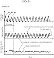
- FIG. 5 is a time chart used to describe the waveforms of the engine speed Ne and MG rotation speed Nmg when no misfire has occurred.
- FIG. 6 is a time chart used to describe the waveforms of the engine speed Ne and MG rotation speed Nmg when a continuous misfire occurs in one specific cylinder.
- the waveforms of the hybrid electric vehicle X referenced to for comparison are shown by thin solid lines
- the waveforms of the series hybrid electric vehicle 1 according to the first embodiment are shown by thick solid lines.
- these figures show the waveforms during the fast idle operation accompanied by the catalyst warm-up, and the engine speed Ne changes around a constant value (1300 rpm as an example).
- combustion torque (engine torque Te) is generated in the order of the first cylinder #1, the second cylinder #2, and the third cylinder #3 during one cycle.
- the engine speed Ne fluctuates in conjunction with this change in combustion torque.
- the engine speed Ne in the series hybrid electric vehicle 1 will fluctuate in the same manner as that in the hybrid electric vehicle X.
- the torque input from the engine side to the MG side is smoothed by the presence of the torsional damper, but the waveform of the MG rotation speed Nmg in the series hybrid electric vehicle 1 having a relatively small inertia Img fluctuates at a higher frequency than that of the hybrid electric vehicle X.
- the MG rotation speed Nmg fluctuates greatly, unlike the hybrid electric vehicle X, which does not show a large difference from the example without misfire. It should be noted that, in the example of continuous misfire shown in FIG. 6 , the MG rotation speed Nmg fluctuates due to the influence of the resonance of the torsional damper (more detail, the power transmission system).
- the period of the MG rotation speed Nmg in the waveform of the series hybrid electric vehicle 1 having a relatively high resonance frequency is shorter than that in the waveform of the hybrid electric vehicle X having a relatively low resonance frequency (e.g., 9.4 Hz).
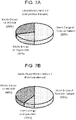
- FIGS. 7A and 7B are diagrams showing the difference in the energy ratio at the time of continuous misfire between the hybrid electric vehicle X and the series hybrid electric vehicle 1.
- the calculation result of the energy ratio shown in FIG. 7 is based on the same test data as that shown in FIG. 6 .
- the torque output from the internal combustion engine 12 i.e., engine torque Te
- the torque output from the internal combustion engine 12 is converted into kinetic energies on the engine side and MG side and strain energy of the torsional damper.
- the ratio of strain energy of the torsional damper is the same.
- the ratio of the kinetic energy on the MG side is clearly higher than the ratio of the kinetic energy on the engine side as compared with the hybrid electric vehicle X. This indicates that, in the series hybrid electric vehicle 1, when a continuous misfire occurs, the rotation fluctuation on the engine side is less likely to occur, while the rotation fluctuation on the MG side is likely to occur.
- the misfire detection process A using the rotation fluctuation on the MG side is executed in order to detect the misfire of the internal combustion engine 12. Specifically, in the misfire detection process A, the processor 22a determines that when an "amplitude correlation value" is greater than a designated determination threshold value, the internal combustion engine 12 has misfired.
- the amplitude correlation value referred to here is a value that correlates with the magnitude of the amplitude of the MG rotation speed Nmg.
- a specific example of the amplitude correlation value used in the first embodiment is, for example, the total amplitude indicated by a symbol E in FIG. 6 .
- the amplitude correlation value may be, for example, one of the amplitudes indicated by symbols F1 and F2 in the same figure (i.e., one of the half amplitudes (in other words, the difference between the maximum value and the average value, or the difference between the average value and the minimum value)).
- This kind of amplitude correlation value can be calculated using, for example, the output signal of the resolver 36.
- the misfire detection itself is basically always executed during the operation of the internal combustion engine 12.
- the above description has been made for the continuous misfire, focusing on the fast idle operating condition accompanied by the catalyst warm-up.
- the misfire detection process A not only the misfire detection under the fast idle operating condition but also all the misfire detections performed during the engine operation are executed by using the misfire detection process A.
- the misfire detection process A is executed regardless of the engine speed Ne used during the engine operation (in other words, regardless of the 0.5th order frequency value of the engine rotation frequency fne).
- the pattern of misfire that can be detected by the misfire detection process A is not limited to the continuous misfire in which the above-described influence of the resonance is reflected on the MG rotation speed Nmg as shown in FIG. 6 . That is, the misfire detection process A can also be used to detect a random misfire, which will be described below, for example, with reference to FIG. 8 .
- FIG. 8 is a time chart used to describe the waveforms of the engine speed Ne and MG rotation speed Nmg when a random misfire occurs.
- the waveforms of the hybrid electric vehicle X referred to for comparison are shown by thin solid lines
- the waveforms of the series hybrid electric vehicle 1 according to the first embodiment are shown by thick solid lines.
- this figure shows waveforms during the fast idle operation accompanied by the catalyst warm-up, and the engine speed Ne changes around a constant value (1300 rpm as an example).
- the engine speed Ne decreases with the occurrence of a misfire as indicated by an arrow G in FIG. 8 .
- the MG rotation speed Nmg is not affected by the resonance of the torsional damper (more specifically, the power transmission system). Therefore, as shown by an arrow H in the same figure, after a large rotation fluctuation occurs on the MG side due to the occurrence of a misfire, the rotation fluctuation on the MG side is immediately converging.
- FIG. 9 is a flowchart showing the flow of the misfire detection process A according to the first embodiment. The process of this flowchart is repeatedly executed during engine operation after the start of the internal combustion engine 12 is completed.
- step S100 the processor 22a calculates the magnitude of the total amplitude of the MG rotation speed Nmg. More specifically, the processor 22a calculates the magnitude of the total amplitude (amplitude correlation value) based on the data of the MG rotation speed Nmg detected by the resolver 36 during a designated crank angle period (e.g., 720°CA corresponding to one cycle) required to calculate the magnitude of the total amplitude. Thereafter, the process proceeds to step S102.
- a designated crank angle period e.g., 720°CA corresponding to one cycle
- step S102 the processor 22a determines whether or not the magnitude of the total amplitude calculated in step S100 is greater than a designated threshold value TH1.
- This threshold value TH1 is predetermined as a value that distinguishes the magnitude of the total amplitude when various patterns of misfires including continuous misfires occur, from the magnitude of the total amplitude when no misfire has occurred.
- step S102 when the magnitude of the total amplitude is smaller than or equal to the threshold value TH1, the process proceeds to step S104.
- step S104 the processor 22a determines that no misfire has occurred in the internal combustion engine 12.
- step S106 the processor 22a determines that a misfire has occurred in the internal combustion engine 12.
- the misfire detection process A for the series hybrid electric vehicle 1 having a small inertia Img on the MG side by using the amplitude correlation value of the rotation fluctuation on the MG side, the accuracy of detecting continuous misfire can be improved by a simple method in an engine operating condition (e.g., fast idle operating condition with catalyst warm-up) that uses a low frequency band (see FIG. 4B ) in which the rotation fluctuation on the MG side is more likely to occur than the rotation fluctuation on the engine side.
- an engine operating condition e.g., fast idle operating condition with catalyst warm-up
- a low frequency band see FIG. 4B
- a complicated process may be used to acquire the engine speed Ne excluding the torsional vibration component of the torsional damper superimposed on the engine speed Ne.
- the misfire detection process A that acquires the rotation fluctuation (i.e., amplitude correlation value) on the MG side by using the rotation angle sensor (resolver) 36, the rotation fluctuation that occurs in the power transmission system P due to the occurrence of continuous misfire can be directly detected. Therefore, continuous misfire can be detected accurately without using the complicated process as described above.
- the magnitude of the total amplitude of the MG rotation speed Nmg is used as the amplitude correlation value.
- the magnitude of the amplitude more specifically, half amplitude or single amplitude
- the misfire detection process A that does not utilize the rotation fluctuation on the engine side, the detectability of continuous misfire under this kind of situation can be effectively improved.
- reducing the retard amount of the ignition timing in order to improve the detectability of the rotation fluctuation on the engine side during the fast idle operation accompanied by catalyst warm-up leads to an increase in the amount of exhaust emission (unburned hydrocarbon HC) because the time required for the catalyst warm-up becomes longer.
- the misfire detection process A the detectability of continuous misfire can be ensured without causing this kind of decrease in the retard amount of the ignition timing.
- a second embodiment is the same as the first embodiment described above, except that the misfire detection process is changed during the operation of the internal combustion engine 12 by the method described below.
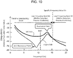
- FIG. 10 is a graph used to describe a method of selecting a misfire detection process according to the second embodiment.
- FIG. 10 shows the same relation as FIG. 4B .
- a specific frequency value fth in FIG. 10 corresponds to the value of the frequency f when the rotation fluctuation index value (more specifically, gain of the transfer function) on the MG side and the rotation fluctuation index value on the engine side intersect (i.e., when they become equal).
- the rotation fluctuation on the MG side is more likely to occur than the rotation fluctuation on the engine side.
- the misfire detection process A described above is selected.
- a misfire detection process B is selected.
- This misfire detection process B is a process of detecting a misfire of the internal combustion engine 12 based on the rotation fluctuation of the crankshaft 12b detected by the crank angle sensor 34, which corresponds to an example of the "second misfire detection process" according to the present invention.
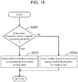
- FIG. 11 is a flowchart showing the flow of the misfire detection process according to the second embodiment. The process of this flowchart is repeatedly executed during engine operation after the start of the internal combustion engine 12 is completed.
- step S200 the processor 22a determines whether or not the 0.5th order frequency value of the engine rotation frequency fne (i.e., the half frequency value of the engine rotation frequency fne) is equal to or less than the specific frequency value fth (see FIG. 10 ).
- the 0.5th order frequency value is calculated using the signal of the crank angle sensor 34.
- step S200 when the 0.5th order frequency value is equal to or less than the specific frequency value fth, the process proceeds to step S202.
- step S202 the processor 22a selects the misfire detection process A using the rotation fluctuation on the MG side. Therefore, the processor 22a executes the process of the flowchart shown in FIG. 9 .
- step S200 when the 0.5th order frequency value is greater than the specific frequency value fth, the process proceeds to step S204.
- the processor 22a selects the misfire detection process B that uses the rotation fluctuation on the engine side that is detected by the crank angle sensor 34.
- the misfire detection process B can be realized by using any known method (for example, the method described in JP 2011-052698 A ) as long as it is a method utilizing the rotation fluctuation on the engine side (i.e., the fluctuation of the engine speed Ne). Therefore, further detailed description of the misfire detection process B is omitted here.
- the misfire detection process A that uses the rotation fluctuation on the MG side is selected, and when the 0.5th order frequency value is greater than the specific frequency value fth, the misfire detection process B that uses the rotation fluctuation on the engine side is selected.
- the misfire detection process A that uses the rotation fluctuation on the MG side is selected
- the 0.5th order frequency value is greater than the specific frequency value fth
- the misfire detection process B that uses the rotation fluctuation on the engine side is selected.
- the misfire detection process A (first misfire detection process) using the rotation fluctuation on the MG side may be executed when the ignition timing is retarded with respect to the optimum ignition timing MBT for the catalyst warm-up or other purposes not only under the fast idle operating condition but also under other engine operating conditions in which the 0.5th order value (i.e., the half frequency value of the engine rotation frequency fne) is equal to or less than the specific frequency value fth (see FIG. 10 ).
- the 0.5th order frequency value (i.e., the half frequency value described above) belongs to the low frequency band B1 (see FIG. 10 ) regardless of the specifications of the series hybrid electric vehicle.
- the misfire detection process A may be executed during a fast idle operation that is not accompanied by the retard of the ignition timing with respect to the optimum ignition timing MBT for catalyst warm-up or other purposes.
- the inertia Img on the MG side is affected by the gear ratio (more specifically, the square of the gear ratio). Therefore, in a power train system configured such that the gear ratio can be changed, during the operation of the internal combustion engine 12, the inertia Img changes in association with the change of the gear ratio, and the inertia ratio R (see FIG. 2 ) also changes. As a result, whether it is appropriate to use the rotation fluctuation on the MG side or the rotation fluctuation on the engine side for misfire detection may differ depending on whether the inertia ratio R is lower or higher than the designated value R1 (see FIG. 2 ) during the operation of the internal combustion engine 12.
- the processor of the engine misfire detection device may be configured to calculate the inertia ratio R during the operation of the internal combustion engine. Then, the processor may select the misfire detection process A (first misfire detection process) when the inertia ratio R is equal to or less than the designated value R1, and may select the misfire detection process B (second misfire detection process) when the inertia ratio R is higher than the designated value R1.
Landscapes
- Engineering & Computer Science (AREA)
- Chemical & Material Sciences (AREA)
- Combustion & Propulsion (AREA)
- Mechanical Engineering (AREA)
- General Engineering & Computer Science (AREA)
- General Physics & Mathematics (AREA)
- Physics & Mathematics (AREA)
- Transportation (AREA)
- Health & Medical Sciences (AREA)
- Biomedical Technology (AREA)
- General Health & Medical Sciences (AREA)
- Automation & Control Theory (AREA)
- Combined Controls Of Internal Combustion Engines (AREA)
- Hybrid Electric Vehicles (AREA)
- Control Of Vehicle Engines Or Engines For Specific Uses (AREA)
Applications Claiming Priority (1)
| Application Number | Priority Date | Filing Date | Title |
|---|---|---|---|
| JP2020188756A JP7327358B2 (ja) | 2020-11-12 | 2020-11-12 | ハイブリッド車両のエンジン失火検出装置 |
Publications (1)
| Publication Number | Publication Date |
|---|---|
| EP4001880A1 true EP4001880A1 (de) | 2022-05-25 |
Family
ID=78621703
Family Applications (1)
| Application Number | Title | Priority Date | Filing Date |
|---|---|---|---|
| EP21208075.8A Pending EP4001880A1 (de) | 2020-11-12 | 2021-11-12 | Vorrichtung zur erkennung von fehlzündungen für ein elektrisches hybridfahrzeug |
Country Status (4)
| Country | Link |
|---|---|
| US (1) | US11459968B2 (de) |
| EP (1) | EP4001880A1 (de) |
| JP (1) | JP7327358B2 (de) |
| CN (1) | CN114483300A (de) |
Families Citing this family (3)
| Publication number | Priority date | Publication date | Assignee | Title |
|---|---|---|---|---|
| WO2021090493A1 (ja) * | 2019-11-08 | 2021-05-14 | 日産自動車株式会社 | 内燃機関の制御方法及び内燃機関の制御装置 |
| CN115182813B (zh) * | 2022-07-26 | 2023-10-20 | 东风汽车集团股份有限公司 | 一种混合动力汽车的发动机失火监测方法 |
| JP7488539B1 (ja) | 2023-06-19 | 2024-05-22 | 武藤 直人 | バッテリー電気自動車用レンジエクステンダ |
Citations (5)
| Publication number | Priority date | Publication date | Assignee | Title |
|---|---|---|---|---|
| JP2000248989A (ja) | 1999-02-25 | 2000-09-12 | Fuji Heavy Ind Ltd | 多気筒エンジンの失火検出装置 |
| JP2001268711A (ja) | 2000-03-22 | 2001-09-28 | Nissan Motor Co Ltd | ハイブリッド車両の制御装置 |
| EP1965066A1 (de) * | 2005-12-21 | 2008-09-03 | Toyota Jidosha Kabushiki Kaisha | Vorrichtung zur beurteilung von fehlzündungen eines verbrennungsmotors und damit versehenes fahrzeug sowie verfahren zur beurteilung von fehlzündungen |
| US20170355376A1 (en) * | 2016-06-08 | 2017-12-14 | Yichao Guo | Response amplitude modification for hybrid electric vehicle misfire detections |
| US20190293519A1 (en) * | 2018-03-23 | 2019-09-26 | Subaru Corporation | Misfire determination apparatus |
Family Cites Families (5)
| Publication number | Priority date | Publication date | Assignee | Title |
|---|---|---|---|---|
| JP4453654B2 (ja) * | 2005-12-21 | 2010-04-21 | トヨタ自動車株式会社 | 内燃機関の失火判定装置およびこれを搭載する車両並びに失火判定方法 |
| JP4492549B2 (ja) * | 2006-01-27 | 2010-06-30 | トヨタ自動車株式会社 | 失火判定装置、ハイブリッド自動車及び失火判定方法 |
| JP6217917B2 (ja) | 2013-12-26 | 2017-10-25 | 三菱自動車工業株式会社 | ハイブリッド車両の制御装置 |
| JP2017105332A (ja) | 2015-12-10 | 2017-06-15 | トヨタ自動車株式会社 | ハイブリッド車両 |
| JP6624325B1 (ja) | 2019-03-29 | 2019-12-25 | トヨタ自動車株式会社 | 内燃機関の失火検出装置、内燃機関の失火検出システム、データ解析装置、内燃機関の制御装置、内燃機関の失火検出方法、および受信実行装置 |
-
2020
- 2020-11-12 JP JP2020188756A patent/JP7327358B2/ja active Active
-
2021
- 2021-11-09 US US17/522,239 patent/US11459968B2/en active Active
- 2021-11-11 CN CN202111353996.0A patent/CN114483300A/zh active Pending
- 2021-11-12 EP EP21208075.8A patent/EP4001880A1/de active Pending
Patent Citations (6)
| Publication number | Priority date | Publication date | Assignee | Title |
|---|---|---|---|---|
| JP2000248989A (ja) | 1999-02-25 | 2000-09-12 | Fuji Heavy Ind Ltd | 多気筒エンジンの失火検出装置 |
| JP2001268711A (ja) | 2000-03-22 | 2001-09-28 | Nissan Motor Co Ltd | ハイブリッド車両の制御装置 |
| EP1965066A1 (de) * | 2005-12-21 | 2008-09-03 | Toyota Jidosha Kabushiki Kaisha | Vorrichtung zur beurteilung von fehlzündungen eines verbrennungsmotors und damit versehenes fahrzeug sowie verfahren zur beurteilung von fehlzündungen |
| JP2011052698A (ja) | 2005-12-21 | 2011-03-17 | Toyota Motor Corp | 内燃機関の失火判定装置およびこれを搭載する車両並びに失火判定方法 |
| US20170355376A1 (en) * | 2016-06-08 | 2017-12-14 | Yichao Guo | Response amplitude modification for hybrid electric vehicle misfire detections |
| US20190293519A1 (en) * | 2018-03-23 | 2019-09-26 | Subaru Corporation | Misfire determination apparatus |
Also Published As
| Publication number | Publication date |
|---|---|
| CN114483300A (zh) | 2022-05-13 |
| US20220145820A1 (en) | 2022-05-12 |
| JP7327358B2 (ja) | 2023-08-16 |
| JP2022077768A (ja) | 2022-05-24 |
| US11459968B2 (en) | 2022-10-04 |
Similar Documents
| Publication | Publication Date | Title |
|---|---|---|
| EP4001880A1 (de) | Vorrichtung zur erkennung von fehlzündungen für ein elektrisches hybridfahrzeug | |
| EP1965066B1 (de) | Vorrichtung zur beurteilung von fehlzündungen eines verbrennungsmotors und damit versehenes fahrzeug sowie verfahren zur beurteilung von fehlzündungen | |
| US7712356B2 (en) | Misfire determination system and method for internal combustion engine, vehicle including misfire determination system for internal combustion engine, and system for and method of estimating rigidity of torsion element | |
| EP2058501B1 (de) | Fehlzündungsbeurteilungsvorrichtung und fehlzündungsbeurteilungsverfahren für verbrennungsmotoren | |
| US7707874B2 (en) | Misfire determination device and method for internal combustion engine, and vehicle including misfire determination device | |
| JP6603348B2 (ja) | 失火判定装置 | |
| US9261433B2 (en) | Misfire detection system of internal combustion engine | |
| US11260846B2 (en) | Driving force control method and device for hybrid vehicle | |
| US11351982B2 (en) | Driving force control method and device for hybrid vehicle | |
| US20120232774A1 (en) | Misfire detecting apparatus for internal combustion engine | |
| US11312355B2 (en) | Driving force control method and device for hybrid vehicle | |
| US11235749B2 (en) | Driving force control method and device for hybrid vehicle | |
| JP2012215178A (ja) | 内燃機関の失火判定装置 | |
| US11230281B2 (en) | Driving force control method and device for hybrid vehicle | |
| US11121651B2 (en) | Driving force control method and device for hybrid vehicle | |
| US10464568B2 (en) | Method and apparatus of controlling vibration of hybrid electric vehicle | |
| JP5108719B2 (ja) | 内燃機関の失火判定装置 | |
| JP2012214224A (ja) | 内燃機関の失火判定装置 |
Legal Events
| Date | Code | Title | Description |
|---|---|---|---|
| PUAI | Public reference made under article 153(3) epc to a published international application that has entered the european phase |
Free format text: ORIGINAL CODE: 0009012 |
|
| STAA | Information on the status of an ep patent application or granted ep patent |
Free format text: STATUS: REQUEST FOR EXAMINATION WAS MADE |
|
| 17P | Request for examination filed |
Effective date: 20211112 |
|
| AK | Designated contracting states |
Kind code of ref document: A1 Designated state(s): AL AT BE BG CH CY CZ DE DK EE ES FI FR GB GR HR HU IE IS IT LI LT LU LV MC MK MT NL NO PL PT RO RS SE SI SK SM TR |
|
| GRAP | Despatch of communication of intention to grant a patent |
Free format text: ORIGINAL CODE: EPIDOSNIGR1 |
|
| STAA | Information on the status of an ep patent application or granted ep patent |
Free format text: STATUS: GRANT OF PATENT IS INTENDED |
|
| RIC1 | Information provided on ipc code assigned before grant |
Ipc: F02P 5/145 20060101ALI20240411BHEP Ipc: F02D 41/00 20060101ALI20240411BHEP Ipc: F02D 41/14 20060101ALI20240411BHEP Ipc: B60W 20/50 20160101ALI20240411BHEP Ipc: F02D 41/06 20060101ALI20240411BHEP Ipc: B60K 6/46 20071001ALI20240411BHEP Ipc: G01M 15/11 20060101AFI20240411BHEP |