EP3999787B1 - Verfahren zur fertigung einer heizvorrichtung sowie heizvorrichtung - Google Patents
Verfahren zur fertigung einer heizvorrichtung sowie heizvorrichtung Download PDFInfo
- Publication number
- EP3999787B1 EP3999787B1 EP20743962.1A EP20743962A EP3999787B1 EP 3999787 B1 EP3999787 B1 EP 3999787B1 EP 20743962 A EP20743962 A EP 20743962A EP 3999787 B1 EP3999787 B1 EP 3999787B1
- Authority
- EP
- European Patent Office
- Prior art keywords
- fan
- heating device
- grid
- speed
- recess
- Prior art date
- Legal status (The legal status is an assumption and is not a legal conclusion. Google has not performed a legal analysis and makes no representation as to the accuracy of the status listed.)
- Active
Links
Images

Classifications
-
- F—MECHANICAL ENGINEERING; LIGHTING; HEATING; WEAPONS; BLASTING
- F24—HEATING; RANGES; VENTILATING
- F24H—FLUID HEATERS, e.g. WATER OR AIR HEATERS, HAVING HEAT-GENERATING MEANS, e.g. HEAT PUMPS, IN GENERAL
- F24H3/00—Air heaters
- F24H3/02—Air heaters with forced circulation
- F24H3/025—Air heaters with forced circulation using fluid fuel
-
- F—MECHANICAL ENGINEERING; LIGHTING; HEATING; WEAPONS; BLASTING
- F23—COMBUSTION APPARATUS; COMBUSTION PROCESSES
- F23L—SUPPLYING AIR OR NON-COMBUSTIBLE LIQUIDS OR GASES TO COMBUSTION APPARATUS IN GENERAL ; VALVES OR DAMPERS SPECIALLY ADAPTED FOR CONTROLLING AIR SUPPLY OR DRAUGHT IN COMBUSTION APPARATUS; INDUCING DRAUGHT IN COMBUSTION APPARATUS; TOPS FOR CHIMNEYS OR VENTILATING SHAFTS; TERMINALS FOR FLUES
- F23L5/00—Blast-producing apparatus before the fire
- F23L5/02—Arrangements of fans or blowers
-
- F—MECHANICAL ENGINEERING; LIGHTING; HEATING; WEAPONS; BLASTING
- F24—HEATING; RANGES; VENTILATING
- F24H—FLUID HEATERS, e.g. WATER OR AIR HEATERS, HAVING HEAT-GENERATING MEANS, e.g. HEAT PUMPS, IN GENERAL
- F24H15/00—Control of fluid heaters
- F24H15/20—Control of fluid heaters characterised by control inputs
-
- F—MECHANICAL ENGINEERING; LIGHTING; HEATING; WEAPONS; BLASTING
- F24—HEATING; RANGES; VENTILATING
- F24H—FLUID HEATERS, e.g. WATER OR AIR HEATERS, HAVING HEAT-GENERATING MEANS, e.g. HEAT PUMPS, IN GENERAL
- F24H15/00—Control of fluid heaters
- F24H15/30—Control of fluid heaters characterised by control outputs; characterised by the components to be controlled
- F24H15/345—Control of fans, e.g. on-off control
- F24H15/35—Control of the speed of fans
-
- F—MECHANICAL ENGINEERING; LIGHTING; HEATING; WEAPONS; BLASTING
- F24—HEATING; RANGES; VENTILATING
- F24H—FLUID HEATERS, e.g. WATER OR AIR HEATERS, HAVING HEAT-GENERATING MEANS, e.g. HEAT PUMPS, IN GENERAL
- F24H3/00—Air heaters
- F24H3/02—Air heaters with forced circulation
- F24H3/022—Air heaters with forced circulation using electric energy supply
-
- F—MECHANICAL ENGINEERING; LIGHTING; HEATING; WEAPONS; BLASTING
- F24—HEATING; RANGES; VENTILATING
- F24H—FLUID HEATERS, e.g. WATER OR AIR HEATERS, HAVING HEAT-GENERATING MEANS, e.g. HEAT PUMPS, IN GENERAL
- F24H6/00—Combined water and air heaters
-
- F—MECHANICAL ENGINEERING; LIGHTING; HEATING; WEAPONS; BLASTING
- F24—HEATING; RANGES; VENTILATING
- F24H—FLUID HEATERS, e.g. WATER OR AIR HEATERS, HAVING HEAT-GENERATING MEANS, e.g. HEAT PUMPS, IN GENERAL
- F24H9/00—Details
- F24H9/18—Arrangement or mounting of grates or heating means
- F24H9/1809—Arrangement or mounting of grates or heating means for water heaters
- F24H9/1832—Arrangement or mounting of combustion heating means, e.g. grates or burners
- F24H9/1836—Arrangement or mounting of combustion heating means, e.g. grates or burners using fluid fuel
-
- F—MECHANICAL ENGINEERING; LIGHTING; HEATING; WEAPONS; BLASTING
- F24—HEATING; RANGES; VENTILATING
- F24H—FLUID HEATERS, e.g. WATER OR AIR HEATERS, HAVING HEAT-GENERATING MEANS, e.g. HEAT PUMPS, IN GENERAL
- F24H9/00—Details
- F24H9/18—Arrangement or mounting of grates or heating means
- F24H9/1854—Arrangement or mounting of grates or heating means for air heaters
- F24H9/1877—Arrangement or mounting of combustion heating means, e.g. grates or burners
- F24H9/1881—Arrangement or mounting of combustion heating means, e.g. grates or burners using fluid fuel
-
- F—MECHANICAL ENGINEERING; LIGHTING; HEATING; WEAPONS; BLASTING
- F24—HEATING; RANGES; VENTILATING
- F24H—FLUID HEATERS, e.g. WATER OR AIR HEATERS, HAVING HEAT-GENERATING MEANS, e.g. HEAT PUMPS, IN GENERAL
- F24H9/00—Details
- F24H9/20—Arrangement or mounting of control or safety devices
- F24H9/2007—Arrangement or mounting of control or safety devices for water heaters
- F24H9/2014—Arrangement or mounting of control or safety devices for water heaters using electrical energy supply
-
- F—MECHANICAL ENGINEERING; LIGHTING; HEATING; WEAPONS; BLASTING
- F24—HEATING; RANGES; VENTILATING
- F24H—FLUID HEATERS, e.g. WATER OR AIR HEATERS, HAVING HEAT-GENERATING MEANS, e.g. HEAT PUMPS, IN GENERAL
- F24H9/00—Details
- F24H9/20—Arrangement or mounting of control or safety devices
- F24H9/2064—Arrangement or mounting of control or safety devices for air heaters
- F24H9/2071—Arrangement or mounting of control or safety devices for air heaters using electrical energy supply
-
- F—MECHANICAL ENGINEERING; LIGHTING; HEATING; WEAPONS; BLASTING
- F24—HEATING; RANGES; VENTILATING
- F24H—FLUID HEATERS, e.g. WATER OR AIR HEATERS, HAVING HEAT-GENERATING MEANS, e.g. HEAT PUMPS, IN GENERAL
- F24H9/00—Details
- F24H9/18—Arrangement or mounting of grates or heating means
- F24H9/1854—Arrangement or mounting of grates or heating means for air heaters
- F24H9/1863—Arrangement or mounting of electric heating means
Definitions
- the invention relates to a method for manufacturing a heating device.
- the invention also relates to a heating device for heating at least one medium.
- the medium is, for example, a liquid (e.g. water) or air (e.g. room air).
- Heating devices are known in the prior art that generate thermal energy by burning propane or butane, which is transferred to air or water as exemplary media via heat exchangers.
- a fan is usually provided that serves to supply the heating device with air.
- the air is used for the burning process itself or represents the medium to be heated.
- the AU 561 321 B2 discloses a multi-purpose fan with an electrically driven fan and a heating coil arranged within the air flow of the fan. Furthermore, a device for controlling the speed of the fan is provided. The fan is arranged behind a grille which has recesses that allow light to pass through.
- the DE 296 07 624 U1 discloses an electric heater with a housing for a heating element with a front grille and a fan. Exhaust air openings are provided in the front grille.
- the US 2013 / 044 997 A1 describes an electric heater comprising an upper housing, a lower housing, and a heater disposed in the upper housing.
- the CA 2 174 812 A1 discloses an electrical device having a portable housing and an electrically powered environmental conditioning device supported by the housing and operable to generate an airflow therethrough.
- the GB 1 099 275 A describes an air heating furnace in a central heating system.
- the GB 1 528 989 A discloses an indirect forced-flow air heater comprising an inlet that supplies air to both a combustion chamber and an air flow path surrounding the chamber.
- a fan draws the air into the inlet, with a portion passing directly into the air flow path and another portion passing through slots to a compressor that feeds the air into the combustion chamber via nozzles in a stoichiometric ratio with fuel.
- the DE 195 31 660 A1 discloses a reflection light barrier with a light beam and an associated receiving system as a sensor for contactless speed measurement of a rotating body.
- the object underlying the invention is to propose an effective method for producing a heating device and a correspondingly effectively manufactured heating device.
- the invention solves the problem according to a first teaching by a method for manufacturing a heating device, wherein the heating device has a fan located behind a grille in an interior of the heating device.
- the method has at least the following steps: the fan is mounted inside the heating device, the grille is mounted as part of the heating device, and the speed of the fan is measured contactlessly by evaluating a Reflection behavior of the fan is determined, wherein at least one light signal is emitted through a recess in the grille in the direction of the fan and/or received through a recess in the grille from the direction of the fan.
- the fan and the grille are assembled during production of the heating device.
- the grille serves as protection for the fan.
- the speed of the fan is determined in one step.
- the contactless measurement of the speed is achieved by providing a recess for light signals in the grille.
- the light signals can therefore pass through the grille unhindered for the measurement. This in turn makes it possible, for example, to assemble the grille before the speed is determined.
- the fan is active while the speed is being measured.
- a fan wheel of the fan rotates at a predetermined speed, which represents a target value for the determined speed.
- a power level can be set for the fan, to which a target value of the speed is then assigned for processing the measurement data.
- One embodiment of the method consists in comparing the determined speed with a target value and generating a comparison result.
- a tolerance band for the permissible level of deviation between the determined speed and the target value of the speed is used to generate the comparison result.
- the fan and/or the heating device is calibrated. Alternatively or additionally, the fan is adjusted based on the comparison result. Alternatively or additionally, the fan is replaced based on the comparison result.
- the determination of the speed is used in the aforementioned embodiments to determine whether the fan corresponds to a setpoint value in terms of speed. If deviations occur - in one embodiment beyond a tolerance band - then this can be responded to with the different embodiments. Calibration can take place, ie the effective speed is taken into account during operation of the heating device or the fan. Alternatively, the fan is subjected to post-processing with regard to adjustment. Alternatively or additionally, the blower is exchanged and replaced by another blower.
- One embodiment of the method provides that the fan and the grille are assembled together before the step of determining the speed.
- the fan and the grille are present as a finished unit during production, which is assembled.
- the fan and the grille are each mounted separately. However, this is done before the step of determining the speed.
- the invention solves the problem according to a further teaching by a heating device for heating at least one medium, wherein the heating device has a fan located behind a grid in an interior of the heating device, and wherein the grid has a recess that allows light to pass through.
- the heating device is preferably manufactured using the method according to one of the aforementioned embodiments.
- the fan has a passage point in a fan wheel and a reflection surface behind the fan wheel.
- the light is reflected on the reflection surface to measure the speed.
- the fan wheel rotates, the light path from a light source, across the reflection surface and to a light detector is interrupted. Based on the knowledge of the emitted and received light signals, the speed of the fan wheel and thus of the blower can be determined in this design.
- the recess represents a deviation from a grid structure of the grid.
- the recess differs from the rest of the grid structure in terms of its shape or geometry.
- One embodiment of the heating device provides that the recess is designed as a circular recess.
- One embodiment of the heating device consists in that the grid is designed as a grid with a grid structure having elongated openings.
- the fan wheel reflects the light and a passage in the fan wheel causes the reflection to be prevented or at least noticeably reduced. This is done, for example, by a surface behind the passage having a strong scattering effect. Alternatively, a change in the running time of the light signals is registered and evaluated.
- the heating device heats several media.
- the media are in particular water or another water-fluid mixture and air.
- the heated air is, for example, room air.
- the Fig.1 shows part of a heating device 1 that serves to heat two media.
- the media here are, for example, air for heating a room and water.
- the fan 3 is located behind a grille 2 that prevents objects from being drawn into the fan 3 or a person from reaching into the fan 3 during operation. It can be seen that the grille 2 has been attached to the housing of the heating device 1 using a screw on the lower left edge.
- the grille 2 generally has a grille structure that is characterized by elongated openings.
- the recess 20 is provided in the area of the fan 3 and is circular in the embodiment shown.
- the recess 20 is thus a deviation from the rest of the grille structure. It allows the speed of the fan 3 to be determined without contact by evaluating the reflection of light signals.
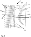
- the Fig. 2 shows the interior 10 of the heating device 1 of the Fig.1 , in which the fan 3 is located behind the grille 2.
- the fan 3 has a fan wheel 30 in which there is a passage 31. Behind this there is a reflection surface 32, which is created here by a fastening rib. If the fan wheel 30 is in a favorable position during rotation, a light signal can pass through the recess 20 in the grille 2 and through the passage 31 in the fan wheel 30 to the reflection surface 32 and be reflected back from there. By rotating the fan wheel 30 there is an interruption in the detection of the light signals, from which the speed can be determined.
- the recess 20 in the grille 2 has the particular advantage that it does not interfere with the measurements even when assembled. This allows, for example, the joint assembly of the fan 3 and the grille 2 as a production component that is already connected to one another.
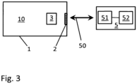
- the Fig.3 shows a schematic representation of a heating device 1 and a device for determining the speed of the fan 3 of the heating device 1.
- the heating device 1 is fully assembled with the fan 3 inside 10 and the grille 2 in the wall of the heating device 1.
- the measuring device 5 has a light transmitting and receiving device 51 and an evaluation device 51 for determining the speed of the fan 3 based on the transmitted and received light signals.
- the fan 3 is operated at a predetermined speed as a target value.
- Light signals 50 are sent by the measuring device 5 and received as reflected signals - e.g. after reflection on the surface of the fan wheel.
- the effective speed is determined from the sequence of received signals in conjunction with the data on the sent signals in order to generate a comparison result in comparison with the target speed.
Landscapes
- Engineering & Computer Science (AREA)
- Chemical & Material Sciences (AREA)
- Combustion & Propulsion (AREA)
- Mechanical Engineering (AREA)
- General Engineering & Computer Science (AREA)
- Physics & Mathematics (AREA)
- Thermal Sciences (AREA)
- Direct Air Heating By Heater Or Combustion Gas (AREA)
- Domestic Hot-Water Supply Systems And Details Of Heating Systems (AREA)
- Baking, Grill, Roasting (AREA)
Description
- Die Erfindung bezieht sich auf ein Verfahren zur Fertigung einer Heizvorrichtung. Weiterhin bezieht sich die Erfindung auf eine Heizvorrichtung zum Erwärmen mindestens eines Mediums. Das Medium ist beispielsweise eine Flüssigkeit (z. B. Wasser) oder Luft (z. B. Raumluft).
- Im Stand der Technik sind Heizvorrichtungen bekannt, die durch das Verbrennen von Propan oder Butan thermische Energie erzeugen, die über Wärmetauscher auf Luft oder Wasser als beispielhafte Medien übertragen wird. Für den Brennvorgang oder auch für das Erwärmen der Raumlauft ist dabei zumeist ein Gebläse vorgesehen, das der Versorgung der Heizvorrichtung mit Luft dient. Die Luft wird je nach Ausgestaltung verwendet für den Brennvorgang selbst oder stellt das zu erwärmende Medium da.
- Bei der Fertigung einer solchen Heizvorrichtung ist es erforderlich, die Drehzahl des Gebläses zu ermitteln. Dies geschieht beispielsweise berührungslos über das Auswerten der Reflexion von Lichtsignalen, siehe z. B. bei einem anderen Anwendungsfall die
DE 198 53 084 A1 . Für eine solche optische Messung ist es erforderlich, dass das Gebläse nicht verdeckt und somit für die Messung zugänglich ist. Dem steht in der Regel entgegen, dass zu Schutzzwecken ein Gitter vor dem Gebläse angeordnet ist. D. h. in der Regel wird das Gebläse montiert, dann wird die Drehzahl ermittelt und schließlich erfolgt die Montage des Gitters. - Die
AU 561 321 B2 - Die
DE 296 07 624 U1 offenbart ein elektrisches Heizgerät mit einem Aufnahmegehäuse für ein Heizelement mit einem Frontgitter und einem Gebläse. In dem Frontgitter sind Abluftöffnungen vorhanden. - Die
US 2013 / 044 997 A1 beschreibt ein elektrisches Heizgerät, das ein oberes Gehäuse, ein unteres Gehäuse und ein im oberen Gehäuse angeordnetes Heizgerät umfasst. - Die
CA 2 174 812 A1 offenbart ein elektrisches Gerät mit einem tragbaren Gehäuse und einer elektrisch betriebenen Umgebungsaufbereitungsvorrichtung, die von dem Gehäuse gehalten wird und betätigbar ist, um einen Luftstrom durch dieses hindurch zu erzeugen. - Die
GB 1 099 275 A - Die
GB 1 528 989 A - Die
DE 195 31 660 A1 offenbart eine Reflexions-Lichtschranke mit einem Lichtstrahl und einem zugehörigen Empfangssystem als Sensor zum berührungslosen Drehzahlmessen eines rotierenden Körpers. - Die der Erfindung zugrundeliegende Aufgabe besteht darin, ein effektives Verfahren zur Herstellung einer Heizvorrichtung sowie eine dementsprechend effektiv gefertigte Heizvorrichtung vorzuschlagen.
- Die Erfindung löst die Aufgabe gemäß einer ersten Lehre durch ein Verfahren zur Fertigung einer Heizvorrichtung, wobei die Heizvorrichtung ein hinter einem Gitter in einem Inneren der Heizvorrichtung befindliches Gebläse aufweist. Das Verfahren weist zumindest folgende Schritte auf: das Gebläse wird im Inneren der Heizvorrichtung montiert, das Gitter wird als Teil der Heizvorrichtung montiert, und die Drehzahl des Gebläses wird berührungslos durch Auswertung eines Reflexionsverhaltens des Gebläses ermittelt, wobei mindestens ein Lichtsignal durch eine Aussparung im Gitter in Richtung des Gebläses ausgesendet und/oder durch eine Aussparung im Gitter aus der Richtung des Gebläses empfangen wird.
- Bei der Fertigung der Heizvorrichtung werden das Gebläse und das Gitter montiert. Das Gitter dient dabei als Schutz für das Gebläse. In einem Schritt wird eine Drehzahl des Gebläses ermittelt. Die berührungslose Messung der Drehzahl wird realisiert, indem in dem Gitter eine Aussparung für Lichtsignale vorhanden ist. Die Lichtsignale können daher für die Messung das Gitter ungehindert passieren. Dies wiederum ermöglicht beispielsweise die Montage des Gitters vor der Ermittlung der Drehzahl. Während der Messung der Drehzahl ist das Gebläse aktiv. Dabei dreht sich vorzugweise ein Lüfterrad des Gebläses mit einer vorgegebenen Drehzahl, die einen Sollwert für die ermittelte Drehzahl darstellt. Alternativ kann auch eine Leistungsstufe für das Gebläse eingestellt werden, der dann für die Verarbeitung der Messdaten ein Sollwert der Drehzahl zugeordnet wird.
- Eine Ausgestaltung des Verfahrens besteht darin, dass die ermittelte Drehzahl mit einem Sollwert verglichen und ein Vergleichsergebnis erzeugt wird. Für die Erzeugung des Vergleichsergebnisses wird in einer Ausgestaltung ein Toleranzband für das zulässige Maß der Abweichungen zwischen der ermittelten Drehzahl und dem Sollwert der Drehzahl benutzt. Ausgehend von dem Vergleichsergebnis wird in einer Ausgestaltung eine Kalibrierung des Gebläses und/oder der Heizvorrichtung vorgenommen. Alternativ oder ergänzend wird ausgehend von dem Vergleichsergebnis eine Justierung des Gebläses vorgenommen. Alternativ oder ergänzend wird ausgehend von dem Vergleichsergebnis das Gebläse ausgetauscht.
- Die Ermittlung der Drehzahl wird in den vorgenannten Ausgestaltungen dazu benutzt, um festzustellen, ob das Gebläse hinsichtlich der Drehzahl einer SollwertVorgabe entspricht. Treten - in einer Ausgestaltung über ein Toleranzband hinaus - Abweichungen auf, so kann darauf mit den unterschiedlichen Ausgestaltungen reagiert werden. So kann eine Kalibrierung stattfinden, d. h. während des Betriebs der Heizvorrichtung oder des Gebläses wird die effektive Drehzahl berücksichtigt. Alternativ wird das Gebläse einer Nachbearbeitung in Bezug auf eine Justierung unterzogen. Wiederum alternativ oder ergänzend wird das Gebläse ausgetauscht und durch ein anderes Gebläse ersetzt.
- Eine Ausgestaltung des Verfahrens sieht vor, dass das Gebläse und das Gitter vor dem Schritt der Ermittlung der Drehzahl gemeinsam montiert werden. In dieser Ausgestaltung sind bei der Fertigung das Gebläse und das Gitter als eine fertige Einheit vorhanden, die montiert wird.
- Alternativ zu der vorangehenden Ausgestaltung werden das Gebläse und das Gitter jeweils separat montiert. Dies geschieht jedoch vor dem Schritt zur Ermittlung der Drehzahl.
- Weiterhin löst die Erfindung die Aufgabe gemäß einer weiteren Lehre durch eine Heizvorrichtung zum Erwärmen mindestens eines Mediums, wobei die Heizvorrichtung ein hinter einem Gitter in einem Inneren der Heizvorrichtung befindliches Gebläse aufweist, und wobei das Gitter eine das Durchqueren von Licht erlaubende Aussparung aufweist. Die Heizvorrichtung ist dabei vorzugsweise mit dem Verfahren nach einer der vorgenannten Ausgestaltungen gefertigt worden.
- Das Gebläse weist eine Durchgangsstelle in einem Lüfterrad und eine hinter dem Lüfterrad befindliche Reflexionsfläche auf. An der Reflexionsfläche wird das Licht für die Messung der Drehzahl reflektiert. Durch das Drehen des Lüfterrads wird dabei der Lichtpfad von einer Lichtquelle, über die Reflexionsfläche und hin zu einem Lichtdetektor unterbrochen. Ausgehend von dem Wissen über die ausgestrahlten und empfangenen Lichtsignale kann in dieser Ausgestaltung die Drehzahl des Lüfterrads und damit des Gebläses ermittelt werden.
- Eine Ausgestaltung der Heizvorrichtung besteht darin, dass die Aussparung eine Abweichung von einer Gitterstruktur des Gitters darstellt. In dieser Ausgestaltung unterscheidet sich somit die Aussparung hinsichtlich ihrer Form oder ihrer Geometrie von der restlichen Gitterstruktur.
- Eine Ausgestaltung der Heizvorrichtung sieht vor, dass die Aussparung als kreisförmige Aussparung ausgestaltet ist.
- Eine Ausgestaltung der Heizvorrichtung besteht darin, dass das Gitter als Gitter mit einer längliche Öffnungen aufweisenden Gitterstruktur ausgestaltet ist.
- In einer alternativen Ausgestaltung reflektiert das Lüfterrad das Licht und bewirkt eine im Lüfterrad befindliche Durchgangsstelle, dass die Reflexion verhindert oder zumindest merkbar reduziert wird. Dies geschieht z. B. dadurch, dass eine Fläche hinter der Durchgangsstelle stark streuend wirkt. Alternativ wird eine Laufzeitänderung der Lichtsignale registriert und ausgewertet.
- Eine Ausgestaltung der Heizvorrichtung besteht darin, dass die Heizvorrichtung mehrere Medien erwärmt. Bei den Medien handelt es sich in einer Ausgestaltung insbesondere um Wasser oder ein anderes Wasser-Fluid-Gemisch und Luft. Die erwärmte Luft ist beispielsweise Raumluft.
- Im Einzelnen gibt es eine Vielzahl von Möglichkeiten, das erfindungsgemäße Verfahren sowie die Heizvorrichtung auszugestalten und weiterzubilden. Dazu wird verwiesen einerseits auf die den unabhängigen Patentansprüchen nachgeordneten Patentansprüche, andererseits auf die folgende Beschreibung von Ausführungsbeispielen in Verbindung mit der Zeichnung. Es zeigen die:
-
Fig. 1 ein Ausschnitt einer Draufsicht auf eine Heizvorrichtung, -
Fig. 2 eine teilweise angeschnittene Sicht auf das Innere der Heizvorrichtung derFig. 1 und -
Fig. 3 eine schematische Darstellung einer Messung der Drehzahl. - Die
Fig. 1 zeigt einen Teil einer Heizvorrichtung 1, die der Erhitzung von zwei Medien dient. Die Medien sind hier beispielhaft Luft für die Erwärmung eines Raumes und Wasser. Dargestellt ist insbesondere der Bereich um ein Gebläse 3, das Frischluft in die Heizvorrichtung 1 hineintransportiert. Das Gebläse 3 befindet sich hinter einem Gitter 2, welches verhindert, dass Gegenstände in das Gebläse 3 hineingezogen werden oder dass während des laufenden Betriebs eine Person in das Gebläse 3 hineingreift. Zu erkennen ist, dass das Gitter 2 über eine Schraube am linken unteren Rand am Gehäuse der Heizvorrichtung 1 befestigt worden ist. - Das Gitter 2 weist im Allgemeinen eine Gitterstruktur auf, die sich durch längliche Öffnungen auszeichnet. Im Bereich des Gebläses 3 ist die Aussparung 20 vorgesehen, die in dem dargestellten Ausführungsbeispiel kreisförmig ist. Die Aussparung 20 ist somit eine Abweichung von der restlichen Gitterstruktur. Sie erlaubt es, berührungslos über die Auswertung der Reflexion von Lichtsignalen die Drehzahl des Gebläses 3 zu ermitteln.
- Die
Fig. 2 zeigt das Innere 10 der Heizvorrichtung 1 derFig. 1 , in welchem sich das Gebläse 3 hinter dem Gitter 2 befindet. - Das Gebläse 3 verfügt über ein Lüfterrad 30, in welchem sich eine Durchgangsstelle 31 befindet. Dahinter liegt eine Reflexionsfläche 32, die hier durch eine Befestigungsrippe erzeugt wird. Steht das Lüfterrad 30 während einer Drehung günstig, so kann ein Lichtsignal durch die Aussparung 20 im Gitter 2 und durch die Durchgangsstelle 31 im Lüfterrad 30 zur Reflexionsfläche 32 gelangen und von dort wieder zurückreflektiert werden. Durch das Drehen des Lüfterrads 30 findet eine Unterbrechung der Detektion der Lichtsignale statt, woraus auf die Drehzahl geschlossen werden kann.
- Die Aussparung 20 im Gitter 2 hat insbesondere den Vorteil, dass es auch im montierten Zustand die Messungen nicht stört. Dies erlaubt beispielsweise die gemeinsame Montage von Gebläse 3 und Gitter 2 als einer bereits miteinander verbundenen Fertigungskomponente.
- Die
Fig. 3 zeigt eine schematische Darstellung einer Heizvorrichtung 1 und einer Vorrichtung zur Ermittlung der Drehzahl des Gebläses 3 der Heizvorrichtung 1. - Die Heizvorrichtung 1 ist fertig montiert mit dem Gebläse 3 im Inneren 10 und dem Gitter 2 in der Wandung der Heizvorrichtung 1.
- Die Messvorrichtung 5 verfügt über eine Lichtsende- und - empfangsvorrichtung 51 und eine Auswertevorrichtung 51 für die Ermittlung der Drehzahl des Gebläses 3 anhand der gesendeten und empfangenen Lichtsignale.
- Bei der Messung wird das Gebläse 3 mit einer vorgegebenen Drehzahl als Sollwert betrieben. Von der Messvorrichtung 5 werden Lichtsignale 50 gesendet und - z. B. nach einer Reflexion an der Oberfläche des Lüfterrads - als reflektierte Signale empfangen. Aus der Abfolge der empfangenen Signale wird im Zusammenhang mit den Daten über die gesendeten Signale die effektive Drehzahl ermittelt, um im Vergleich mit der Solldrehzahl ein Vergleichsergebnis zu erzeugen.
-
- 1
- Heizvorrichtung
- 2
- Gitter
- 3
- Gebläse
- 5
- Messvorrichtung
- 10
- Innere der Heizvorrichtung
- 20
- Aussparung im Gitter
- 30
- Lüfterrad des Gebläses
- 31
- Durchgangsstelle im Lüfterrad
- 32
- Reflexionsfläche
- 50
- Lichtsignal
- 51
- Lichtsende- und -empfangsvorrichtung
- 52
- Auswertevorrichtung
Claims (7)
- Verfahren zur Fertigung einer Heizvorrichtung (1), wobei die Heizvorrichtung (1) ein hinter einem Gitter (2) in einem Inneren (10) der Heizvorrichtung (1) befindliches Gebläse (3) aufweist, und wobei das Verfahren zumindest folgende Schritte aufweist:das Gebläse (3) wird im Inneren (10) der Heizvorrichtung (1) montiert,das Gitter (2) wird als Teil der Heizvorrichtung (1) montiert, unddie Drehzahl des Gebläses (3) wird berührungslos durch Auswertung eines Reflexionsverhaltens des Gebläses (3) ermittelt, wobei mindestens ein Lichtsignal (50) durch eine Aussparung (20) im Gitter (2) in Richtung des Gebläses (3) ausgesendet und/oder durch eine Aussparung (20) im Gitter (2) aus der Richtung des Gebläses (3) empfangen wird.
- Verfahren nach Anspruch 1, wobei die ermittelte Drehzahl mit einem Sollwert verglichen und ein Vergleichsergebnis erzeugt wird, und wobei ausgehend von dem Vergleichsergebnis eine Kalibrierung des Gebläses (3) und/oder der Heizvorrichtung (1) vorgenommen wird oder eine Justierung des Gebläses (3) vorgenommen wird oder das Gebläse ausgetauscht wird.
- Verfahren nach Anspruch 1 oder 2, wobei das Gebläse (3) und das Gitter (2) vor dem Schritt der Ermittlung der Drehzahl gemeinsam montiert werden.
- Heizvorrichtung (1) zum Erwärmen mindestens eines Mediums, wobei die Heizvorrichtung (1) ein hinter einem Gitter (2) in einem Inneren (10) der Heizvorrichtung (1) befindliches Gebläse (3) aufweist, und wobei das Gitter (2) eine das Durchqueren von Licht erlaubende Aussparung (20) aufweist, dadurch gekennzeichnet, dass das Gebläse (3) eine Durchgangsstelle (31) in einem Lüfterrad (30) und eine hinter dem Lüfterrad (30) befindliche Reflexionsfläche (32) aufweist.
- Heizvorrichtung (1) nach Anspruch 4, wobei die Aussparung (20) eine Abweichung von einer Gitterstruktur des Gitters (2) darstellt.
- Heizvorrichtung (1) nach Anspruch 4 oder 5, wobei die Aussparung (20) als kreisförmige Aussparung (20) ausgestaltet ist.
- Heizvorrichtung (1) nach einem der Ansprüche 4 bis 6, wobei das Gitter (2) als Gitter (2) mit einer längliche Öffnungen aufweisenden Gitterstruktur ausgestaltet ist.
Applications Claiming Priority (2)
| Application Number | Priority Date | Filing Date | Title |
|---|---|---|---|
| DE102019004952.7A DE102019004952A1 (de) | 2019-07-17 | 2019-07-17 | Verfahren zur Fertigung einer Heizvorrichtung sowie Heizvorrichtung |
| PCT/EP2020/000129 WO2021008719A1 (de) | 2019-07-17 | 2020-07-10 | Verfahren zur fertigung einer heizvorrichtung sowie heizvorrichtung |
Publications (2)
| Publication Number | Publication Date |
|---|---|
| EP3999787A1 EP3999787A1 (de) | 2022-05-25 |
| EP3999787B1 true EP3999787B1 (de) | 2024-08-28 |
Family
ID=71741749
Family Applications (1)
| Application Number | Title | Priority Date | Filing Date |
|---|---|---|---|
| EP20743962.1A Active EP3999787B1 (de) | 2019-07-17 | 2020-07-10 | Verfahren zur fertigung einer heizvorrichtung sowie heizvorrichtung |
Country Status (7)
| Country | Link |
|---|---|
| US (1) | US20220243957A1 (de) |
| EP (1) | EP3999787B1 (de) |
| CN (1) | CN114144624A (de) |
| AU (1) | AU2020312473B2 (de) |
| CA (1) | CA3141899A1 (de) |
| DE (1) | DE102019004952A1 (de) |
| WO (1) | WO2021008719A1 (de) |
Family Cites Families (10)
| Publication number | Priority date | Publication date | Assignee | Title |
|---|---|---|---|---|
| GB1099275A (en) * | 1965-06-16 | 1968-01-17 | Vono Ltd | Central heating system |
| US4002157A (en) * | 1974-12-31 | 1977-01-11 | Energy Transformation Corporation | Gas turbine heating apparatus |
| AU561321B2 (en) * | 1981-08-17 | 1987-05-07 | Mistral Kempthorne Limited | Multi purpose fan |
| CA2174812A1 (en) * | 1995-05-15 | 1996-11-16 | Rodney Jane | Portable environmental conditioning device with presence detector responsive shutoff |
| DE19531660A1 (de) * | 1995-08-29 | 1997-03-06 | Betr Forsch Inst Angew Forsch | Reflexions-Lichtschranke |
| DE19613989A1 (de) * | 1996-04-09 | 1997-10-16 | Ewt Elektrogeraete Gmbh & Co K | Elektrisches Heizgerät |
| DE19853084A1 (de) | 1998-11-18 | 2000-05-25 | Schlafhorst & Co W | Verfahren und Vorrichtung zur berührungslosen Drehzahlmessung eines rotierenden Körpers |
| GB0505280D0 (en) * | 2005-03-16 | 2005-04-20 | Chung Mei Ind Ltd | Low noise fan heater |
| US20130044997A1 (en) * | 2011-08-16 | 2013-02-21 | Irvin M. French | Electric convection heater and method of use for exterminating insects |
| US11166770B2 (en) * | 2016-09-19 | 2021-11-09 | Intuitive Surgical Operations, Inc. | Base positioning system for a controllable arm and related methods |
-
2019
- 2019-07-17 DE DE102019004952.7A patent/DE102019004952A1/de not_active Withdrawn
-
2020
- 2020-07-10 CN CN202080051666.3A patent/CN114144624A/zh active Pending
- 2020-07-10 WO PCT/EP2020/000129 patent/WO2021008719A1/de not_active Ceased
- 2020-07-10 AU AU2020312473A patent/AU2020312473B2/en active Active
- 2020-07-10 US US17/597,574 patent/US20220243957A1/en active Pending
- 2020-07-10 CA CA3141899A patent/CA3141899A1/en active Pending
- 2020-07-10 EP EP20743962.1A patent/EP3999787B1/de active Active
Also Published As
| Publication number | Publication date |
|---|---|
| AU2020312473B2 (en) | 2025-09-25 |
| CA3141899A1 (en) | 2021-01-21 |
| AU2020312473A1 (en) | 2022-01-06 |
| CN114144624A (zh) | 2022-03-04 |
| DE102019004952A1 (de) | 2021-01-21 |
| EP3999787A1 (de) | 2022-05-25 |
| WO2021008719A1 (de) | 2021-01-21 |
| US20220243957A1 (en) | 2022-08-04 |
Similar Documents
| Publication | Publication Date | Title |
|---|---|---|
| EP2270762B1 (de) | Rauchwarnmelder und Verfahren zur Überprüfung der Verschmutzung der Rauchdurchtrittsöffnungen | |
| DE102016216074A1 (de) | Vorrichtung zum gleichzeitigen Messen der Innentemperatur und des Feinstaubs in einem Fahrzeug | |
| EP2154435B1 (de) | Verfahren zum Überwachen und Führen eines Garprozesses | |
| EP3097403B1 (de) | Vorrichtung zur bestimmung der konzentration zumindest eines gases in einem probengasstrom mittels infrarotabsorptionsspektroskopie | |
| EP2508811B1 (de) | Vorrichtung zur Ermittlung des von einem Ventilator transportierten Volumenstroms | |
| DE2601326A1 (de) | Vorrichtung zur messung der staubmenge in gasen | |
| DE2103048A1 (de) | Temperaturmeßvorrichtung | |
| DE102009009426A1 (de) | Messverfahren und Messvorrichtung zur Bestimmung von Eigenschaften eines mit Partikeln beladenen Fluidstroms | |
| EP4323721A1 (de) | Verfahren zum betreiben eines gargeräts und gargerät | |
| DE102014211514B4 (de) | Verfahren zur Bestimmung des Durchsatzes, des Volumenstromes und des Massenstromes von Teilchen | |
| EP1416266A1 (de) | Verfahren zur Überprüfung der Struktur von Durchgangslöchern eines Bauteils | |
| WO2024017832A1 (de) | Selbstfahrendes und selbstlenkendes bodenreinigungsgerät, bodenreinigungssystem und verfahren zum betreiben eines bodenreinigungsgerätes | |
| DE102016101862A1 (de) | Verfahren zur Bestimmung einer Temperatur, System zur Bestimmung einer Temperatur und Verwenden eines Systems zur Bestimmung einer Temperatur | |
| DE102017210123A1 (de) | Luftleitsystem sowie Messsystem und Verfahren zum Ermitteln von wenigstens einem Parameter eines aus einem Luftausströmer austretenden Luftstroms | |
| EP3999787A1 (de) | Verfahren zur fertigung einer heizvorrichtung sowie heizvorrichtung | |
| WO2015197227A1 (de) | Vorrichtung und verfahren zum kalibrieren eines streulichtmessgerätes | |
| EP2183064B1 (de) | Warmwalzstrasse umfassend eine haspel une eine vorrichtung zur ermittlung einer temperatur eines warmwalzgutes und verfahren zur steuerung und/oder regelung einer temperatur eines warmwalzguts | |
| WO1996038701A1 (de) | Verfahren zur reinigung vorgebbarer flächen eines beheizbaren innenraumes sowie zugehöriger wasserlanzenbläser | |
| WO2012171786A1 (de) | Automatische identifikation der wellenlänge eines lasers | |
| EP2042830B1 (de) | Vorrichtung und Verfahren zur Radialspaltmessung mit Millimeterwellen | |
| DE102015110583A1 (de) | Thermostat für Heizungs-, Klima, und/oder Lüftungsanlagen | |
| EP1397650A1 (de) | Verfahren und vorrichtung zur diagnostik und überwachung eines unfokussierten laserstrahles von hochleistungs-laseranlagen | |
| EP4062124A1 (de) | Verfahren zur erfassung einer axialen verlängerung einer rotierenden welle relativ zu einem gehäuse | |
| EP2659325B1 (de) | Hausgerätevorrichtung | |
| EP2737299A1 (de) | Vorrichtung und verfahren zur messung der partikelkonzentration in einem aerosol |
Legal Events
| Date | Code | Title | Description |
|---|---|---|---|
| STAA | Information on the status of an ep patent application or granted ep patent |
Free format text: STATUS: UNKNOWN |
|
| STAA | Information on the status of an ep patent application or granted ep patent |
Free format text: STATUS: THE INTERNATIONAL PUBLICATION HAS BEEN MADE |
|
| PUAI | Public reference made under article 153(3) epc to a published international application that has entered the european phase |
Free format text: ORIGINAL CODE: 0009012 |
|
| STAA | Information on the status of an ep patent application or granted ep patent |
Free format text: STATUS: REQUEST FOR EXAMINATION WAS MADE |
|
| 17P | Request for examination filed |
Effective date: 20220110 |
|
| AK | Designated contracting states |
Kind code of ref document: A1 Designated state(s): AL AT BE BG CH CY CZ DE DK EE ES FI FR GB GR HR HU IE IS IT LI LT LU LV MC MK MT NL NO PL PT RO RS SE SI SK SM TR |
|
| DAV | Request for validation of the european patent (deleted) | ||
| DAX | Request for extension of the european patent (deleted) | ||
| P01 | Opt-out of the competence of the unified patent court (upc) registered |
Effective date: 20230514 |
|
| GRAP | Despatch of communication of intention to grant a patent |
Free format text: ORIGINAL CODE: EPIDOSNIGR1 |
|
| STAA | Information on the status of an ep patent application or granted ep patent |
Free format text: STATUS: GRANT OF PATENT IS INTENDED |
|
| RIC1 | Information provided on ipc code assigned before grant |
Ipc: F24H 15/35 20220101ALI20240301BHEP Ipc: F24H 15/20 20220101ALI20240301BHEP Ipc: F24H 6/00 20060101ALI20240301BHEP Ipc: F24H 9/20 20060101ALI20240301BHEP Ipc: F24H 3/02 20060101AFI20240301BHEP |
|
| INTG | Intention to grant announced |
Effective date: 20240320 |
|
| GRAS | Grant fee paid |
Free format text: ORIGINAL CODE: EPIDOSNIGR3 |
|
| GRAA | (expected) grant |
Free format text: ORIGINAL CODE: 0009210 |
|
| STAA | Information on the status of an ep patent application or granted ep patent |
Free format text: STATUS: THE PATENT HAS BEEN GRANTED |
|
| AK | Designated contracting states |
Kind code of ref document: B1 Designated state(s): AL AT BE BG CH CY CZ DE DK EE ES FI FR GB GR HR HU IE IS IT LI LT LU LV MC MK MT NL NO PL PT RO RS SE SI SK SM TR |
|
| REG | Reference to a national code |
Ref country code: CH Ref legal event code: EP |
|
| REG | Reference to a national code |
Ref country code: DE Ref legal event code: R096 Ref document number: 502020009040 Country of ref document: DE |
|
| REG | Reference to a national code |
Ref country code: IE Ref legal event code: FG4D Free format text: LANGUAGE OF EP DOCUMENT: GERMAN |
|
| REG | Reference to a national code |
Ref country code: LT Ref legal event code: MG9D |
|
| PG25 | Lapsed in a contracting state [announced via postgrant information from national office to epo] |
Ref country code: NO Free format text: LAPSE BECAUSE OF FAILURE TO SUBMIT A TRANSLATION OF THE DESCRIPTION OR TO PAY THE FEE WITHIN THE PRESCRIBED TIME-LIMIT Effective date: 20241128 |
|
| PG25 | Lapsed in a contracting state [announced via postgrant information from national office to epo] |
Ref country code: NL Free format text: LAPSE BECAUSE OF FAILURE TO SUBMIT A TRANSLATION OF THE DESCRIPTION OR TO PAY THE FEE WITHIN THE PRESCRIBED TIME-LIMIT Effective date: 20240828 Ref country code: PL Free format text: LAPSE BECAUSE OF FAILURE TO SUBMIT A TRANSLATION OF THE DESCRIPTION OR TO PAY THE FEE WITHIN THE PRESCRIBED TIME-LIMIT Effective date: 20240828 Ref country code: GR Free format text: LAPSE BECAUSE OF FAILURE TO SUBMIT A TRANSLATION OF THE DESCRIPTION OR TO PAY THE FEE WITHIN THE PRESCRIBED TIME-LIMIT Effective date: 20241129 Ref country code: FI Free format text: LAPSE BECAUSE OF FAILURE TO SUBMIT A TRANSLATION OF THE DESCRIPTION OR TO PAY THE FEE WITHIN THE PRESCRIBED TIME-LIMIT Effective date: 20240828 Ref country code: PT Free format text: LAPSE BECAUSE OF FAILURE TO SUBMIT A TRANSLATION OF THE DESCRIPTION OR TO PAY THE FEE WITHIN THE PRESCRIBED TIME-LIMIT Effective date: 20241230 |
|
| PG25 | Lapsed in a contracting state [announced via postgrant information from national office to epo] |
Ref country code: BG Free format text: LAPSE BECAUSE OF FAILURE TO SUBMIT A TRANSLATION OF THE DESCRIPTION OR TO PAY THE FEE WITHIN THE PRESCRIBED TIME-LIMIT Effective date: 20240828 |
|
| PG25 | Lapsed in a contracting state [announced via postgrant information from national office to epo] |
Ref country code: LV Free format text: LAPSE BECAUSE OF FAILURE TO SUBMIT A TRANSLATION OF THE DESCRIPTION OR TO PAY THE FEE WITHIN THE PRESCRIBED TIME-LIMIT Effective date: 20240828 |
|
| REG | Reference to a national code |
Ref country code: NL Ref legal event code: MP Effective date: 20240828 |
|
| PG25 | Lapsed in a contracting state [announced via postgrant information from national office to epo] |
Ref country code: IS Free format text: LAPSE BECAUSE OF FAILURE TO SUBMIT A TRANSLATION OF THE DESCRIPTION OR TO PAY THE FEE WITHIN THE PRESCRIBED TIME-LIMIT Effective date: 20241228 |
|
| PG25 | Lapsed in a contracting state [announced via postgrant information from national office to epo] |
Ref country code: HR Free format text: LAPSE BECAUSE OF FAILURE TO SUBMIT A TRANSLATION OF THE DESCRIPTION OR TO PAY THE FEE WITHIN THE PRESCRIBED TIME-LIMIT Effective date: 20240828 |
|
| PG25 | Lapsed in a contracting state [announced via postgrant information from national office to epo] |
Ref country code: RS Free format text: LAPSE BECAUSE OF FAILURE TO SUBMIT A TRANSLATION OF THE DESCRIPTION OR TO PAY THE FEE WITHIN THE PRESCRIBED TIME-LIMIT Effective date: 20241128 Ref country code: ES Free format text: LAPSE BECAUSE OF FAILURE TO SUBMIT A TRANSLATION OF THE DESCRIPTION OR TO PAY THE FEE WITHIN THE PRESCRIBED TIME-LIMIT Effective date: 20240828 |
|
| PG25 | Lapsed in a contracting state [announced via postgrant information from national office to epo] |
Ref country code: RS Free format text: LAPSE BECAUSE OF FAILURE TO SUBMIT A TRANSLATION OF THE DESCRIPTION OR TO PAY THE FEE WITHIN THE PRESCRIBED TIME-LIMIT Effective date: 20241128 Ref country code: PT Free format text: LAPSE BECAUSE OF FAILURE TO SUBMIT A TRANSLATION OF THE DESCRIPTION OR TO PAY THE FEE WITHIN THE PRESCRIBED TIME-LIMIT Effective date: 20241230 Ref country code: PL Free format text: LAPSE BECAUSE OF FAILURE TO SUBMIT A TRANSLATION OF THE DESCRIPTION OR TO PAY THE FEE WITHIN THE PRESCRIBED TIME-LIMIT Effective date: 20240828 Ref country code: NO Free format text: LAPSE BECAUSE OF FAILURE TO SUBMIT A TRANSLATION OF THE DESCRIPTION OR TO PAY THE FEE WITHIN THE PRESCRIBED TIME-LIMIT Effective date: 20241128 Ref country code: NL Free format text: LAPSE BECAUSE OF FAILURE TO SUBMIT A TRANSLATION OF THE DESCRIPTION OR TO PAY THE FEE WITHIN THE PRESCRIBED TIME-LIMIT Effective date: 20240828 Ref country code: LV Free format text: LAPSE BECAUSE OF FAILURE TO SUBMIT A TRANSLATION OF THE DESCRIPTION OR TO PAY THE FEE WITHIN THE PRESCRIBED TIME-LIMIT Effective date: 20240828 Ref country code: IS Free format text: LAPSE BECAUSE OF FAILURE TO SUBMIT A TRANSLATION OF THE DESCRIPTION OR TO PAY THE FEE WITHIN THE PRESCRIBED TIME-LIMIT Effective date: 20241228 Ref country code: HR Free format text: LAPSE BECAUSE OF FAILURE TO SUBMIT A TRANSLATION OF THE DESCRIPTION OR TO PAY THE FEE WITHIN THE PRESCRIBED TIME-LIMIT Effective date: 20240828 Ref country code: GR Free format text: LAPSE BECAUSE OF FAILURE TO SUBMIT A TRANSLATION OF THE DESCRIPTION OR TO PAY THE FEE WITHIN THE PRESCRIBED TIME-LIMIT Effective date: 20241129 Ref country code: FI Free format text: LAPSE BECAUSE OF FAILURE TO SUBMIT A TRANSLATION OF THE DESCRIPTION OR TO PAY THE FEE WITHIN THE PRESCRIBED TIME-LIMIT Effective date: 20240828 Ref country code: ES Free format text: LAPSE BECAUSE OF FAILURE TO SUBMIT A TRANSLATION OF THE DESCRIPTION OR TO PAY THE FEE WITHIN THE PRESCRIBED TIME-LIMIT Effective date: 20240828 Ref country code: BG Free format text: LAPSE BECAUSE OF FAILURE TO SUBMIT A TRANSLATION OF THE DESCRIPTION OR TO PAY THE FEE WITHIN THE PRESCRIBED TIME-LIMIT Effective date: 20240828 |
|
| PG25 | Lapsed in a contracting state [announced via postgrant information from national office to epo] |
Ref country code: SM Free format text: LAPSE BECAUSE OF FAILURE TO SUBMIT A TRANSLATION OF THE DESCRIPTION OR TO PAY THE FEE WITHIN THE PRESCRIBED TIME-LIMIT Effective date: 20240828 Ref country code: RO Free format text: LAPSE BECAUSE OF FAILURE TO SUBMIT A TRANSLATION OF THE DESCRIPTION OR TO PAY THE FEE WITHIN THE PRESCRIBED TIME-LIMIT Effective date: 20240828 Ref country code: DK Free format text: LAPSE BECAUSE OF FAILURE TO SUBMIT A TRANSLATION OF THE DESCRIPTION OR TO PAY THE FEE WITHIN THE PRESCRIBED TIME-LIMIT Effective date: 20240828 |
|
| PG25 | Lapsed in a contracting state [announced via postgrant information from national office to epo] |
Ref country code: EE Free format text: LAPSE BECAUSE OF FAILURE TO SUBMIT A TRANSLATION OF THE DESCRIPTION OR TO PAY THE FEE WITHIN THE PRESCRIBED TIME-LIMIT Effective date: 20240828 |
|
| PG25 | Lapsed in a contracting state [announced via postgrant information from national office to epo] |
Ref country code: CZ Free format text: LAPSE BECAUSE OF FAILURE TO SUBMIT A TRANSLATION OF THE DESCRIPTION OR TO PAY THE FEE WITHIN THE PRESCRIBED TIME-LIMIT Effective date: 20240828 |
|
| PG25 | Lapsed in a contracting state [announced via postgrant information from national office to epo] |
Ref country code: SK Free format text: LAPSE BECAUSE OF FAILURE TO SUBMIT A TRANSLATION OF THE DESCRIPTION OR TO PAY THE FEE WITHIN THE PRESCRIBED TIME-LIMIT Effective date: 20240828 Ref country code: IT Free format text: LAPSE BECAUSE OF FAILURE TO SUBMIT A TRANSLATION OF THE DESCRIPTION OR TO PAY THE FEE WITHIN THE PRESCRIBED TIME-LIMIT Effective date: 20240828 |
|
| REG | Reference to a national code |
Ref country code: DE Ref legal event code: R097 Ref document number: 502020009040 Country of ref document: DE |
|
| PLBE | No opposition filed within time limit |
Free format text: ORIGINAL CODE: 0009261 |
|
| STAA | Information on the status of an ep patent application or granted ep patent |
Free format text: STATUS: NO OPPOSITION FILED WITHIN TIME LIMIT |
|
| 26N | No opposition filed |
Effective date: 20250530 |
|
| PG25 | Lapsed in a contracting state [announced via postgrant information from national office to epo] |
Ref country code: SE Free format text: LAPSE BECAUSE OF FAILURE TO SUBMIT A TRANSLATION OF THE DESCRIPTION OR TO PAY THE FEE WITHIN THE PRESCRIBED TIME-LIMIT Effective date: 20240828 |
|
| PGFP | Annual fee paid to national office [announced via postgrant information from national office to epo] |
Ref country code: DE Payment date: 20250729 Year of fee payment: 6 |
|
| PGFP | Annual fee paid to national office [announced via postgrant information from national office to epo] |
Ref country code: GB Payment date: 20250728 Year of fee payment: 6 |
|
| PGFP | Annual fee paid to national office [announced via postgrant information from national office to epo] |
Ref country code: FR Payment date: 20250725 Year of fee payment: 6 |
|
| REG | Reference to a national code |
Ref country code: CH Ref legal event code: H13 Free format text: ST27 STATUS EVENT CODE: U-0-0-H10-H13 (AS PROVIDED BY THE NATIONAL OFFICE) Effective date: 20260224 |
|
| PG25 | Lapsed in a contracting state [announced via postgrant information from national office to epo] |
Ref country code: LU Free format text: LAPSE BECAUSE OF NON-PAYMENT OF DUE FEES Effective date: 20250710 |
|
| REG | Reference to a national code |
Ref country code: BE Ref legal event code: MM Effective date: 20250731 |
|
| PG25 | Lapsed in a contracting state [announced via postgrant information from national office to epo] |
Ref country code: BE Free format text: LAPSE BECAUSE OF NON-PAYMENT OF DUE FEES Effective date: 20250731 |
|
| PG25 | Lapsed in a contracting state [announced via postgrant information from national office to epo] |
Ref country code: CH Free format text: LAPSE BECAUSE OF NON-PAYMENT OF DUE FEES Effective date: 20250731 |