EP3996943B1 - Elektrische antriebseinheit für ein kraftfahrzeug - Google Patents
Elektrische antriebseinheit für ein kraftfahrzeug Download PDFInfo
- Publication number
- EP3996943B1 EP3996943B1 EP20746549.3A EP20746549A EP3996943B1 EP 3996943 B1 EP3996943 B1 EP 3996943B1 EP 20746549 A EP20746549 A EP 20746549A EP 3996943 B1 EP3996943 B1 EP 3996943B1
- Authority
- EP
- European Patent Office
- Prior art keywords
- electric drive
- drive unit
- housing
- annular chamber
- unit according
- Prior art date
- Legal status (The legal status is an assumption and is not a legal conclusion. Google has not performed a legal analysis and makes no representation as to the accuracy of the status listed.)
- Active
Links
Images


Classifications
-
- F—MECHANICAL ENGINEERING; LIGHTING; HEATING; WEAPONS; BLASTING
- F16—ENGINEERING ELEMENTS AND UNITS; GENERAL MEASURES FOR PRODUCING AND MAINTAINING EFFECTIVE FUNCTIONING OF MACHINES OR INSTALLATIONS; THERMAL INSULATION IN GENERAL
- F16H—GEARING
- F16H57/00—General details of gearing
- F16H57/04—Features relating to lubrication or cooling or heating
- F16H57/048—Type of gearings to be lubricated, cooled or heated
- F16H57/0482—Gearings with gears having orbital motion
- F16H57/0486—Gearings with gears having orbital motion with fixed gear ratio
-
- B—PERFORMING OPERATIONS; TRANSPORTING
- B60—VEHICLES IN GENERAL
- B60K—ARRANGEMENT OR MOUNTING OF PROPULSION UNITS OR OF TRANSMISSIONS IN VEHICLES; ARRANGEMENT OR MOUNTING OF PLURAL DIVERSE PRIME-MOVERS IN VEHICLES; AUXILIARY DRIVES FOR VEHICLES; INSTRUMENTATION OR DASHBOARDS FOR VEHICLES; ARRANGEMENTS IN CONNECTION WITH COOLING, AIR INTAKE, GAS EXHAUST OR FUEL SUPPLY OF PROPULSION UNITS IN VEHICLES
- B60K1/00—Arrangement or mounting of electrical propulsion units
-
- B—PERFORMING OPERATIONS; TRANSPORTING
- B60—VEHICLES IN GENERAL
- B60K—ARRANGEMENT OR MOUNTING OF PROPULSION UNITS OR OF TRANSMISSIONS IN VEHICLES; ARRANGEMENT OR MOUNTING OF PLURAL DIVERSE PRIME-MOVERS IN VEHICLES; AUXILIARY DRIVES FOR VEHICLES; INSTRUMENTATION OR DASHBOARDS FOR VEHICLES; ARRANGEMENTS IN CONNECTION WITH COOLING, AIR INTAKE, GAS EXHAUST OR FUEL SUPPLY OF PROPULSION UNITS IN VEHICLES
- B60K11/00—Arrangement in connection with cooling of propulsion units
- B60K11/02—Arrangement in connection with cooling of propulsion units with liquid cooling
-
- B—PERFORMING OPERATIONS; TRANSPORTING
- B60—VEHICLES IN GENERAL
- B60K—ARRANGEMENT OR MOUNTING OF PROPULSION UNITS OR OF TRANSMISSIONS IN VEHICLES; ARRANGEMENT OR MOUNTING OF PLURAL DIVERSE PRIME-MOVERS IN VEHICLES; AUXILIARY DRIVES FOR VEHICLES; INSTRUMENTATION OR DASHBOARDS FOR VEHICLES; ARRANGEMENTS IN CONNECTION WITH COOLING, AIR INTAKE, GAS EXHAUST OR FUEL SUPPLY OF PROPULSION UNITS IN VEHICLES
- B60K17/00—Arrangement or mounting of transmissions in vehicles
- B60K17/04—Arrangement or mounting of transmissions in vehicles characterised by arrangement, location or kind of gearing
- B60K17/043—Transmission unit disposed in on near the vehicle wheel, or between the differential gear unit and the wheel
- B60K17/046—Transmission unit disposed in on near the vehicle wheel, or between the differential gear unit and the wheel with planetary gearing having orbital motion
-
- B—PERFORMING OPERATIONS; TRANSPORTING
- B60—VEHICLES IN GENERAL
- B60K—ARRANGEMENT OR MOUNTING OF PROPULSION UNITS OR OF TRANSMISSIONS IN VEHICLES; ARRANGEMENT OR MOUNTING OF PLURAL DIVERSE PRIME-MOVERS IN VEHICLES; AUXILIARY DRIVES FOR VEHICLES; INSTRUMENTATION OR DASHBOARDS FOR VEHICLES; ARRANGEMENTS IN CONNECTION WITH COOLING, AIR INTAKE, GAS EXHAUST OR FUEL SUPPLY OF PROPULSION UNITS IN VEHICLES
- B60K7/00—Disposition of motor in, or adjacent to, traction wheel
- B60K7/0007—Disposition of motor in, or adjacent to, traction wheel the motor being electric
-
- F—MECHANICAL ENGINEERING; LIGHTING; HEATING; WEAPONS; BLASTING
- F16—ENGINEERING ELEMENTS AND UNITS; GENERAL MEASURES FOR PRODUCING AND MAINTAINING EFFECTIVE FUNCTIONING OF MACHINES OR INSTALLATIONS; THERMAL INSULATION IN GENERAL
- F16H—GEARING
- F16H57/00—General details of gearing
- F16H57/02—Gearboxes; Mounting gearing therein
- F16H57/029—Gearboxes; Mounting gearing therein characterised by means for sealing the gearboxes, e.g. to improve airtightness
-
- F—MECHANICAL ENGINEERING; LIGHTING; HEATING; WEAPONS; BLASTING
- F16—ENGINEERING ELEMENTS AND UNITS; GENERAL MEASURES FOR PRODUCING AND MAINTAINING EFFECTIVE FUNCTIONING OF MACHINES OR INSTALLATIONS; THERMAL INSULATION IN GENERAL
- F16H—GEARING
- F16H57/00—General details of gearing
- F16H57/04—Features relating to lubrication or cooling or heating
- F16H57/042—Guidance of lubricant
- F16H57/0421—Guidance of lubricant on or within the casing, e.g. shields or baffles for collecting lubricant, tubes, pipes, grooves, channels or the like
- F16H57/0424—Lubricant guiding means in the wall of or integrated with the casing, e.g. grooves, channels, holes
-
- F—MECHANICAL ENGINEERING; LIGHTING; HEATING; WEAPONS; BLASTING
- F16—ENGINEERING ELEMENTS AND UNITS; GENERAL MEASURES FOR PRODUCING AND MAINTAINING EFFECTIVE FUNCTIONING OF MACHINES OR INSTALLATIONS; THERMAL INSULATION IN GENERAL
- F16H—GEARING
- F16H57/00—General details of gearing
- F16H57/04—Features relating to lubrication or cooling or heating
- F16H57/048—Type of gearings to be lubricated, cooled or heated
- F16H57/0482—Gearings with gears having orbital motion
- F16H57/0484—Gearings with gears having orbital motion with variable gear ratio or for reversing rotary motion
-
- B—PERFORMING OPERATIONS; TRANSPORTING
- B60—VEHICLES IN GENERAL
- B60K—ARRANGEMENT OR MOUNTING OF PROPULSION UNITS OR OF TRANSMISSIONS IN VEHICLES; ARRANGEMENT OR MOUNTING OF PLURAL DIVERSE PRIME-MOVERS IN VEHICLES; AUXILIARY DRIVES FOR VEHICLES; INSTRUMENTATION OR DASHBOARDS FOR VEHICLES; ARRANGEMENTS IN CONNECTION WITH COOLING, AIR INTAKE, GAS EXHAUST OR FUEL SUPPLY OF PROPULSION UNITS IN VEHICLES
- B60K1/00—Arrangement or mounting of electrical propulsion units
- B60K2001/001—Arrangement or mounting of electrical propulsion units one motor mounted on a propulsion axle for rotating right and left wheels of this axle
-
- B—PERFORMING OPERATIONS; TRANSPORTING
- B60—VEHICLES IN GENERAL
- B60K—ARRANGEMENT OR MOUNTING OF PROPULSION UNITS OR OF TRANSMISSIONS IN VEHICLES; ARRANGEMENT OR MOUNTING OF PLURAL DIVERSE PRIME-MOVERS IN VEHICLES; AUXILIARY DRIVES FOR VEHICLES; INSTRUMENTATION OR DASHBOARDS FOR VEHICLES; ARRANGEMENTS IN CONNECTION WITH COOLING, AIR INTAKE, GAS EXHAUST OR FUEL SUPPLY OF PROPULSION UNITS IN VEHICLES
- B60K1/00—Arrangement or mounting of electrical propulsion units
- B60K2001/003—Arrangement or mounting of electrical propulsion units with means for cooling the electrical propulsion units
-
- B—PERFORMING OPERATIONS; TRANSPORTING
- B60—VEHICLES IN GENERAL
- B60K—ARRANGEMENT OR MOUNTING OF PROPULSION UNITS OR OF TRANSMISSIONS IN VEHICLES; ARRANGEMENT OR MOUNTING OF PLURAL DIVERSE PRIME-MOVERS IN VEHICLES; AUXILIARY DRIVES FOR VEHICLES; INSTRUMENTATION OR DASHBOARDS FOR VEHICLES; ARRANGEMENTS IN CONNECTION WITH COOLING, AIR INTAKE, GAS EXHAUST OR FUEL SUPPLY OF PROPULSION UNITS IN VEHICLES
- B60K7/00—Disposition of motor in, or adjacent to, traction wheel
- B60K2007/0092—Disposition of motor in, or adjacent to, traction wheel the motor axle being coaxial to the wheel axle
-
- F—MECHANICAL ENGINEERING; LIGHTING; HEATING; WEAPONS; BLASTING
- F16—ENGINEERING ELEMENTS AND UNITS; GENERAL MEASURES FOR PRODUCING AND MAINTAINING EFFECTIVE FUNCTIONING OF MACHINES OR INSTALLATIONS; THERMAL INSULATION IN GENERAL
- F16H—GEARING
- F16H57/00—General details of gearing
- F16H57/02—Gearboxes; Mounting gearing therein
- F16H2057/02034—Gearboxes combined or connected with electric machines
-
- F—MECHANICAL ENGINEERING; LIGHTING; HEATING; WEAPONS; BLASTING
- F16—ENGINEERING ELEMENTS AND UNITS; GENERAL MEASURES FOR PRODUCING AND MAINTAINING EFFECTIVE FUNCTIONING OF MACHINES OR INSTALLATIONS; THERMAL INSULATION IN GENERAL
- F16H—GEARING
- F16H57/00—General details of gearing
- F16H57/02—Gearboxes; Mounting gearing therein
- F16H2057/02039—Gearboxes for particular applications
- F16H2057/02043—Gearboxes for particular applications for vehicle transmissions
- F16H2057/02052—Axle units; Transfer casings for four wheel drive
-
- F—MECHANICAL ENGINEERING; LIGHTING; HEATING; WEAPONS; BLASTING
- F16—ENGINEERING ELEMENTS AND UNITS; GENERAL MEASURES FOR PRODUCING AND MAINTAINING EFFECTIVE FUNCTIONING OF MACHINES OR INSTALLATIONS; THERMAL INSULATION IN GENERAL
- F16H—GEARING
- F16H2200/00—Transmissions for multiple ratios
- F16H2200/20—Transmissions using gears with orbital motion
- F16H2200/2002—Transmissions using gears with orbital motion characterised by the number of sets of orbital gears
- F16H2200/2007—Transmissions using gears with orbital motion characterised by the number of sets of orbital gears with two sets of orbital gears
-
- F—MECHANICAL ENGINEERING; LIGHTING; HEATING; WEAPONS; BLASTING
- F16—ENGINEERING ELEMENTS AND UNITS; GENERAL MEASURES FOR PRODUCING AND MAINTAINING EFFECTIVE FUNCTIONING OF MACHINES OR INSTALLATIONS; THERMAL INSULATION IN GENERAL
- F16H—GEARING
- F16H57/00—General details of gearing
- F16H57/04—Features relating to lubrication or cooling or heating
- F16H57/0467—Elements of gearings to be lubricated, cooled or heated
- F16H57/0469—Bearings or seals
- F16H57/0471—Bearing
Definitions
- the invention relates to an electric drive unit for a motor vehicle, with an electric drive, a multi-stage transmission connected downstream of the electric drive, which is arranged alone or together with the electric drive in a drive housing, which is composed of a housing shell, the inside of which surrounds the transmission in a ring, and an end wall formed integrally with the housing shell, which is provided centrally with a transmission opening for the transmission output shaft of the transmission, wherein coolant is passed through the drive housing to cool the components of the transmission, wherein an annular chamber is formed on the outside of the end wall around the transmission opening, wherein coolant channels are formed in the drive housing and lead from the inside of the housing shell into the annular chamber.
- Such an electric drive unit serves as a vehicle's drive system. It is used as a component of an electric drive axle for a commercial vehicle.
- a multi-stage transmission is connected downstream of the electric drive, which is positioned close to the center of the vehicle for weight-saving reasons.
- the transmission is arranged alone or together with the electric drive in a drive housing, which consists of a substantially cylindrical housing shell and an end wall formed integrally with the housing shell.
- the inner surface of the housing shell of the drive housing surrounds the transmission elements mounted therein in a ring, and the end wall of the drive housing is provided with a central transmission opening through which the transmission output shaft leads out of the transmission.
- the transmission output shaft is either simultaneously the drive shaft leading to the respective vehicle wheel, or it is connected in a rotationally fixed manner to a separate drive shaft.
- the transmission output shaft or the drive shaft rotates in a predominantly tubular axle housing of the electric drive axle.
- the axle housing is rigidly attached to the front of the drive housing with its end facing the gearbox and has a steering knuckle at its other end on which the driven vehicle wheel is rotatably mounted.
- coolant is passed through the drive housing, which serves as the transmission housing, in the form of a circuit in which the coolant flows through as many mechanically stressed areas of the transmission as possible, including the existing rolling bearings, for which purpose the coolant is circulated within the drive housing.
- the US 5,443,130 discloses a differential gear comprising an input element connected to an electric motor and two output elements, from which the engine power received by the input element is distributed to a first wheel drive element and an intermediate shaft extending through a hollow output shaft of the motor and connected to a second wheel drive element.
- the invention is based on the object of improving the cooling performance of an electric drive unit, the component of which is a drive housing with a liquid-cooled gear arranged therein, by utilizing precisely the design-related special features of the electric drive unit.
- an axle housing enclosing the transmission output shaft is proposed in an electric drive unit of the type specified at the outset, which axle housing is provided with a flange facing the drive housing, which flange is fastened to the end wall and wherein an annular plate of the flange forms the annular chamber together with the end face.
- annular chamber is therefore part of the coolant circulation system.
- this chamber is not located inside the drive housing, but rather on the outside of the drive housing's front wall around the transmission opening.
- coolant channels are formed in the drive housing, which lead from the inside of the housing shell into the annular chamber.
- the arrangement of the annular chamber on the outside of the end wall of the drive housing is advantageous because the drive housing offers little space reserves inside, and because, due to its design, the electric drive axle already includes an axle housing, which is attached to the end wall where, according to the invention, the annular chamber is located.
- the axle housing is provided with a flange facing the drive housing. The flange of the axle housing is attached to the end wall, and an annular portion of the flange, together with the groove formed in the end wall, forms the annular chamber.
- annular chamber for circulating the coolant can be created, which is partially defined by the end wall of the drive housing and partially by an annular area on the axle housing.
- the annular chamber is therefore not formed solely by the drive housing, but by the design-related combination of the drive housing and the axle housing attached to the front side and surrounding the transmission output shaft.
- a preferred embodiment is one in which the annular chamber is partially formed, namely on the side of the drive housing, by a groove in the outer side of the end wall.
- the axle housing is a component of the electric drive axle and is provided with a steering knuckle at its end facing away from the flange for supporting a vehicle wheel.
- a coolant connection piece is arranged on the flange, and a coolant channel leads from the coolant connection piece into the annular chamber in order, for example, to fill it with fresh coolant or, in the case of active circulation cooling, to continuously pump coolant into it.
- first and a second seal between the flange and the end wall.
- first seal is an annular seal arranged between the annular chamber and the central transmission opening
- second seal is an annular seal arranged around the annular chamber.
- the annular seals are seated in annular grooves open toward the outside of the end wall, wherein the annular grooves are formed in the end wall.
- the two seals are arranged axially offset from one another in the longitudinal direction of the transmission output shaft, the second seal being the seal closer to the drive side.
- further coolant channels are formed in the drive housing, wherein the further coolant channels lead from the annular chamber through the end wall to its inner side.
- the coolant can therefore leave the annular chamber via these further coolant channels and flow back into the interior of the drive housing.
- the further coolant channels are bores arranged on a diameter with respect to the central axis. which is smaller than the diameter on which the coolant channels are arranged.
- the flange of the axle housing be secured to the end wall of the drive housing by means of a plurality of screws arranged on a common pitch circle.
- the diameter of the pitch circle is preferably larger than the largest diameter of the annular chamber, and preferably larger than the diameter of the second seal.
- the screws engage with their threads in threaded holes formed in the end wall.
- coolant channels lead into the annular chamber on those circumferential sections on which no threaded blind holes are formed in the end wall.
- end wall and the flange are axially aligned with each other by centring surfaces formed on them and in mutual contact.
- the centering surfaces are arranged on a diameter that is smaller than the smallest diameter of the annular chamber and larger than the diameter of the first seal.
- Fig. 3 shows in a partial longitudinal section, which serves here as an overview, one half of an electric drive axle for a motor vehicle.
- the illustrated half of the drive axle serves to drive a Fig. 3 on the left edge of the vehicle wheel 2 shown in dashed lines.
- the second half of the drive axle which is designed in the same way, is located symmetrically on the other side of the Fig. 3 registered vehicle center plane M, and carries the respective vehicle wheel on the other side of the vehicle.
- the electric drive axle as a whole is a rigid axle running from one side of the vehicle to the other.
- an electric drive 5 in particular an electric motor
- a transmission 6 here in the form of a two-stage planetary gear, is connected downstream of each electric motor on the outside of the vehicle.
- the two electric drives 5 and two transmissions 6 of the electric drive unit are located in a drive housing 4, which can be single-part or multi-part.
- the drive housing 4 consists of three parts or sections, with both electric drives 5 located in a common drive housing section, and each of the two transmissions 6 in a separate, separate drive housing section.
- the electric drive 5 and its transmission 6 can be arranged in a common drive housing 4 for each side of the vehicle.
- the drive housing 4 is therefore also the gear housing of the drive unit and is composed of a substantially cylindrical housing shell 11, which surrounds the gear elements of the gear 6 in a ring shape with its inner side 11a, and of an end wall 12 formed integrally with the housing shell 11.
- the end wall 12 is predominantly closed, but leaves a gear opening 17 free in its center, through which the gear output shaft 18 of the gear 6, rotating on the central axis of rotation A, passes.
- the transmission output shaft 18 can be connected, preferably via a spline, in a rotationally fixed manner to a drive shaft, which leads to and drives the vehicle wheel 2. Unlike the transmission output shaft 18, the drive shaft is not shown in the drawing.
- the drive shaft rotates in a tubular axle housing 15 of the drive unit, which extends along the central axis A.
- the axle housing 15 is attached to the front side of the drive housing 4.
- the axle housing 15 of the drive unit is provided with the steering knuckle 1 at its outer end. Furthermore, the brake carrier of the vehicle brake, preferably the brake carrier of a disc brake, is attached to the axle housing 15. Also attached to the axle housing 15 are a trailing arm and, if applicable, a transverse arm of the vehicle axle.
- the axle housing 15 is provided with a radially expanded flange 16 at its inner end.
- the flange 16 is rigidly screwed to the end wall 12 of the drive housing 4 by means of several screws 19.
- the screws 19 are supported by their screw heads on the flange 16 and engage with their threads in threaded blind holes 20 formed in the end wall 12.
- the drive housing parts i.e., the drive housing part accommodating the electric drive 5 on the one hand and the drive housing part accommodating the gearbox 6 on the other hand, are also connected by means of screw connections 29, for which purpose the respective ends of these drive housing parts are designed as flanges that are firmly and preferably fluid-tightly connected to one another via the screw connections 29.
- the drive housing 4 is referred to generally below, this refers to the drive housing part in which the gearbox 6 and preferably two-stage planetary gears are located.
- the drive housing not only has the housing function, but it is also part of the planetary gear unit, in that according to Fig. 1
- the inner side 11a of the housing shell 11 has a helical gearing 17a of the first gear stage arranged around the rotational axis A, and an axially offset helical gearing 17b of the second gear stage arranged around the rotational axis A.
- the orientation or inclination of the teeth of the helical gearing 17b is opposite to the teeth of the first helical gearing 17a.
- the planetary gears of the two gear stages of the planetary gear mesh with the helical gears 17a, 17b formed on the inside of the housing shell 11.
- the remaining gear elements of the planetary gear are arranged in a gear carrier 17c, which is rotatable on axis A and is inserted into the drive housing 4 as a preassembled unit.
- the transmission 6 is of the planetary gear type.
- the planetary gears and ring gears of the planetary gear have inclined teeth, which generate a blade effect on the coolant directed away from the end wall 12, and in the case of passive sump cooling, generate a blade effect on the coolant directed toward the end wall 12.
- the central part of the gear carrier 17c is the gear output shaft 18 rotating on the axis A, which protrudes from the likewise centrally arranged gear opening 17 of the drive housing 4 and extends into the axle housing 15.
- connection piece 21 is located on the flange 16 of the axle housing 15.
- the cooling fluid is preferably a gear oil, so that the fluid both lubricates the gear elements and dissipates heat.
- cooling and lubricating fluid Due to the planetary gear design, cooling and lubricating fluid is thrown outwards from the planetary gears against the helical gears 17a, 17b due to centrifugal forces.
- the cooling fluid therefore collects on the inner side 11a of the housing shell 11.
- the cooling and lubricating fluids described in more detail below Measures are taken to transport the fluid accumulating on the inner side 11a of the housing shell 11 back into more central areas of the gearbox 6 and into the area of rolling bearings, for example to the rolling bearings 31 of the gearbox output shaft 18.
- annular chamber 33 is arranged on the outside of the end wall 12 in the form of a complete ring, surrounding the central axis of rotation A and the gear opening 17, in which coolant can collect for further circulation.
- several coolant channels 35 are formed in the transition area between the housing shell 11 and the end wall 12 of the drive housing. These channels lead from the inner side 11a of the housing shell 11 into the annular chamber 33. Liquid collected on the inside of the housing shell 11 and in particular on the helical gears 17a, 17b therefore first passes through the coolant channels 35 into the annular chamber 33, which thus forms a collector for coolant.
- annular chamber 33 requires space that is not available in the very compact drive housing 4. Therefore, the annular chamber 33 is located on the outside of the end face of the drive housing 4 facing the vehicle wheel 2. Importantly, the annular chamber 33 is not formed solely by the drive housing 4 itself, but also partly by the axle housing 15. This is achieved by forming the annular chamber 33 partly by an annular groove formed in the outer side of the end wall 12, and partly by an annular region on the end face of the flange 16. The annular region on the end face of the flange 16, together with the groove formed in the end wall 12, thus forms the annular chamber 33, so that not only components of the transmission are involved in the coolant flow and circulation, but also other components of the drive unit, namely the flange 16 of the axle housing 15.
- a plurality of said coolant channels 35 are provided, wherein the coolant channels 35 are preferably arranged uniformly distributed over the circumference of the round drive housing 4.
- the coolant collected in the annular chamber 33 returns to the interior of the drive housing 4 via additional coolant channels 41.
- the additional coolant channels 41 are also present in large numbers and are evenly distributed around the circumference of the round drive housing 4. They lead from the annular chamber 33 through the end wall 12 and each open at the inner side 12a of the end wall 12.
- each coolant channel 35 In order to transport the cooling medium accumulated in the area of the inner side 11a into the annular chamber 33, the coolant channels 35 extend at an incline to the central axis A of the drive unit.
- the opening of each coolant channel 35 into the interior of the drive housing 4 is located radially further outward than the opening of each coolant channel 35 into the annular chamber 33.
- Fig. 2 The coolant channels 35, on the one hand, and the additional coolant channels 41, on the other hand, open into the channel-shaped annular chamber 33 in such a way that the additional coolant channels 41 open at the bottom 42 of the annular chamber 33, and the coolant channels 35 open into a side wall 43 of the annular chamber 33 arranged obliquely to the bottom 42.
- the side wall 43 of the channel into which the coolant channels 35 open is arranged obliquely to the bottom 42 of the channel, whereas the other side wall is arranged substantially perpendicular to the bottom 42 of the channel. This configuration achieves a uniform coolant distribution within the annular chamber 33.
- the annular chamber 33 is sealed radially inward by a first seal 51 and radially outward by a second seal 52, so that no fluid can escape either inwardly or outwardly.
- both seals 51, 52 are ring seals arranged around the central axis A.
- the groove for receiving the respective ring seal is formed in the end face of the end wall 12.
- the end wall 12 and the flange 16 are axially aligned with each other by means of centering surfaces 55 formed thereon and in mutual contact.
- the centering surfaces in the form of a step extending in an annular shape around the central axis A are arranged on a diameter that is smaller than the smallest diameter of the annular chamber 33.
- the annular centering surfaces 55 are therefore located radially between the annular chamber 33 and the inner, first seal 51.
- the threaded blind holes 20 on the one hand and the coolant channels 35 on different circumferential sections are arranged ( Fig. 2 ).
- a screw 19 or its threaded blind hole 20 can alternate with one of the coolant channels 35.
- the design according to Fig. 2 in which the number of coolant channels 35 is half as large as the number of screws 19 or threaded blind holes 20.
- Fig. 4 The additional coolant channels 41 are aligned so that the coolant emerging from them flows almost directly to the rolling bearing 31 that supports the transmission output shaft 18 in the housing shell 11. This improves the cooling as well as the lubrication of this heavily loaded rolling bearing 31.
- the radial sealing of the transmission output shaft 18 with respect to the surrounding transmission opening 17 is achieved by means of a radial shaft sealing ring 58 arranged between these components.
Landscapes
- Engineering & Computer Science (AREA)
- General Engineering & Computer Science (AREA)
- Mechanical Engineering (AREA)
- Chemical & Material Sciences (AREA)
- Combustion & Propulsion (AREA)
- Transportation (AREA)
- General Details Of Gearings (AREA)
- Arrangement Or Mounting Of Propulsion Units For Vehicles (AREA)
- Hybrid Electric Vehicles (AREA)
Description
- Die Erfindung betrifft eine elektrische Antriebseinheit für ein Kraftfahrzeug, mit einem Elektroantrieb, einem dem Elektroantrieb nachgeschalteten mehrstufigen Getriebe, welches allein oder zusammen mit dem Elektroantrieb in einem Antriebsgehäuse angeordnet ist, das sich zusammensetzt aus einem Gehäusemantel, der mit seiner Innenseite das Getriebe ringförmig umgibt, und einer einstückig mit dem Gehäusemantel ausgebildeten Stirnwand, die zentral mit einer Getriebeöffnung für die Getriebeausgangswelle des Getriebes versehen ist, wobei zur Kühlung der Bauteile des Getriebes Kühlflüssigkeit durch das Antriebsgehäuse geleitet wird, wobei eine außen an der Stirnwand um die Getriebeöffnung herum angeordnete Ringkammer ausgebildet ist, wobei in dem Antriebsgehäuse Kühlmittelkanäle ausgebildet sind, die ausgehend von der Innenseite des Gehäusemantels in die Ringkammer führen.
- Eine solche elektrische Antriebseinheit dient als Fahrantrieb eines Fahrzeugs. Zum Einsatz kommt sie als Bestandteil einer elektrischen Antriebsachse für ein Nutzfahrzeug. Bei dieser Bauart einer Fahrzeugachse ist dem gewichtsgünstig nahe der Fahrzeugmitte angeordneten Elektroantrieb ein mehrstufiges Getriebe nachgeschaltet. Das Getriebe ist allein oder zusammen mit dem Elektroantrieb in einem Antriebsgehäuse angeordnet, welches sich aus einem im Wesentlichen zylindrischen Gehäusemantel und einer mit dem Gehäusemantel einstückig ausgebildeten Stirnwand zusammensetzt. Der Gehäusemantel des Antriebsgehäuses umgibt mit seiner Innenseite ringförmig die darin gelagerten Getriebeelemente, und die Stirnwand des Antriebsgehäuses ist zentral mit einer Getriebeöffnung versehen, durch die die Getriebeausgangswelle aus dem Getriebe herausführt. Die Getriebeausgangswelle ist entweder zugleich die zum jeweiligen Fahrzeugrad führende Antriebswelle, oder sie ist drehfest mit einer separaten Antriebswelle verbunden. Die Getriebeausgangswelle bzw. die Antriebswelle rotiert in einem überwiegend rohrförmigen Achsgehäuse der elektrischen Antriebsachse. Das Achsgehäuse ist mit seinem dem Getriebe zugewandten Ende starr an der Stirnseite des Antriebsgehäuses befestigt und weist an seinem anderen Ende einen Achsschenkel auf, auf dem das angetriebene Fahrzeugrad drehbar gelagert ist.
- Zur Kühlung der Getriebeelemente wird Kühlflüssigkeit durch das als Getriebegehäuse dienende Antriebsgehäuse geleitet, wobei dies in Form eines Kreislaufs erfolgt, bei dem die Kühlflüssigkeit möglichst alle mechanisch belasteten Bereiche des Getriebes einschließlich der vorhandenen Wälzlagerungen durchströmt, wozu die Kühlflüssigkeit innerhalb des Antriebsgehäuses umgewälzt wird.
- Die Umwälzung der Kühlflüssigkeit innerhalb des Antriebsgehäuses stößt bei mechanisch hoch belasteten Getrieben an Grenzen, da die Getriebe oft von sehr kompakter Bauart sind und wenig Bauraumreserven vorhanden sind, um die für eine nochmals verbesserte Kühlleistung erforderlichen Baugruppen in dem vorhandenen Gehäuse unterzubringen.
- Die
US 5 443 130 offenbart ein Differentialgetriebe umfassend ein mit einem Elektromotor verbundenes Eingangselement und zwei Ausgangselemente, von denen die von dem Eingangselement empfangene Motorleistung auf ein erstes Radantriebselement und eine Zwischenwelle, die sich durch eine hohle Abtriebswelle des Motors erstreckt und mit einem zweiten Radantriebselement verbunden ist, verteilt wird. - Der Erfindung liegt die Aufgabe zugrunde, bei einer elektrischen Antriebseinheit, deren Bestandteil ein Antriebsgehäuse mit einem darin angeordneten, flüssigkeitsgekühlten Getriebe ist, die Kühlleistung unter Ausnutzung gerade der bauartbedingten Besonderheiten der elektrischen Antriebseinheit zu verbessern.
- Zur Lösung dieser Aufgabe wird bei einer elektrischen Antriebseinheit der eingangs angegebenen Art ein die Getriebeausgangswelle umschließendes Achsgehäuse vorgeschlagen, welches dem Antriebsgehäuse zugewandt mit einem Flansch versehen ist, der an der Stirnwand befestigt ist und wobei ein Ringblech des Flansches gemeinsam mit der Stirnseite die Ringkammer bildet.
- Erfindungsgemäß ist daher Bestandteil der Kühlmittelumwälzung eine Ringkammer, die allerdings nicht im Inneren des Antriebsgehäuses angeordnet ist, sondern außen an der Stirnwand des Antriebsgehäuses um die Getriebeöffnung herum angeordnet ist. Damit Kühlflüssigkeit in diese Ringkammer gelangt, sind in dem Antriebsgehäuse Kühlmittelkanäle ausgebildet, die ausgehend von der Innenseite des Gehäusemantels in die Ringkammer führen.
- Die Anordnung der Ringkammer außen an der Stirnwand des Antriebsgehäuses ist von Vorteil, da das Antriebsgehäuse in seinem Inneren wenig Bauraumreserven bietet, und da Bestandteil der elektrischen Antriebsachse bauartbedingt ohnehin ein Achsgehäuse ist, welches an jener Stirnwand befestigt ist, an der sich erfindungsgemäß die Ringkammer befindet. Das Achsgehäuse ist dem Antriebsgehäuse zugewandt mit einem Flansch versehen. Der Flansch des Achsgehäuses ist an der Stirnwand befestigt, und ein Ringbereich des Flansches bildet gemeinsam mit der in der Stirnwand ausgebildeten Rinne die Ringkammer.
- Aufgrund der bauartbedingten Besonderheit der elektrischen Antriebsachse lässt sich daher eine Ringkammer für das Umwälzen der Kühlflüssigkeit realisieren, die zum Teil durch die Stirnwand des Antriebsgehäuses begrenzt wird, und zum anderen Teil durch einen Ringbereich an dem Achsgehäuse. Die Ringkammer wird also nicht allein durch das Antriebsgehäuse gebildet, sondern durch die bauartbedingte Kombination aus Antriebsgehäuse und dem daran stirnseitig befestigten, die Getriebeausgangswelle umgebenden Achsgehäuse.
- Bevorzugt ist eine Ausgestaltung, bei der die Ringkammer teilweise, nämlich seitens des Antriebsgehäuses, durch eine Rinne in der Außenseite der Stirnwand gebildet wird.
- Das Achsgehäuse ist Bestandteil der elektrischen Antriebsachse und ist an seinem dem Flansch abgewandten Ende mit einem Achsschenkel zur Lagerung eines Fahrzeugrades versehen.
- Gemäß einer Ausgestaltung der Antriebseinheit ist an dem Flansch ein Kühlmittel-Anschlussstutzen angeordnet, und ein Kühlmittelkanal führt von dem Kühlmittel-Anschlussstutzen in die Ringkammer, um diese z. B. mit frischem Kühlmittel zu befüllen oder im Fall einer aktiven Umlaufkühlung Kühlmittel kontinuierlich hineinzupumpen.
- Ferner bevorzugt ist eine erste und eine zweite Abdichtung zwischen dem Flansch und der Stirnwand. Vorzugsweise ist die erste Abdichtung eine zwischen der Ringkammer und der zentralen Getriebeöffnung angeordnete Ringdichtung, und die zweite Abdichtung ist eine um die Ringkammer herum angeordnete Ringdichtung. Vorzugsweise sitzen die Ringdichtungen in zu der Außenseite der Stirnwand hin offenen Ringnuten, wobei die Ringnuten in der Stirnwand ausgebildet sind.
- Gemäß einer weiteren Ausgestaltung sind die beiden Abdichtungen in Längsrichtung der Getriebeausgangswelle axial zueinander versetzt angeordnet, wobei die zweite Abdichtung die näher antriebsseitige Abdichtung ist.
- Gemäß einer weiteren Ausgestaltung sind in dem Antriebsgehäuse weitere Kühlmittelkanäle ausgebildet, wobei die weiteren Kühlmittelkanäle von der Ringkammer durch die Stirnwand hindurch bis an deren Innenseite führen. Über diese weiteren Kühlmittelkanäle kann daher das Kühlmittel die Ringkammer verlassen und wieder zurück in das Innere des Antriebsgehäuses strömen. Vorzugsweise sind die weiteren Kühlmittelkanäle Bohrungen, die in Bezug auf die zentrale Achse auf einem Durchmesser angeordnet sind, der geringer ist als der Durchmesser, auf dem die Kühlmittelkanäle angeordnet sind.
- Herstellungstechnisch von Vorteil ist es, wenn die Achsen der weiteren Kühlmittelkanäle parallel zu der zentralen Achse ausgerichtet sind.
- Hinsichtlich einer günstigen Durchströmung der Ringkammer ist es von Vorteil, wenn die weiteren Kühlmittelkanäle an den Boden, und die Kühlmittelkanäle in der Seitenwand der als Rinne ausgebildeten Ringkammer münden.
- Ferner wird vorgeschlagen, dass der Flansch des Achsgehäuses mittels einer Mehrzahl auf einem gemeinsamen Teilkreis angeordneter Schrauben an der Stirnwand des Antriebsgehäuses befestigt ist. Vorzugsweise ist der Durchmesser des Teilkreises größer als der größte Durchmesser der Ringkammer, und vorzugsweise größer als der Durchmesser der zweiten Abdichtung.
- Vorzugsweise greifen die Schrauben mit ihrem Gewinde in Gewindesachlöcher ein, die in der Stirnwand ausgebildet sind.
- Für eine kompakte Bauart des Antriebsgehäuses und der Befestigung des Achsgehäuses daran ist von Vorteil, wenn die Kühlmittelkanäle auf solchen Umfangsabschnitten in die Ringkammer führen, auf denen in der Stirnwand keine Gewindesacklöcher ausgebildet sind.
- Ferner wird vorgeschlagen, dass die Stirnwand und der Flansch durch an ihnen ausgebildete und in gegenseitigem Kontakt stehende Zentrierflächen axial zueinander ausgerichtet sind.
- Vorzugsweise sind die Zentrierflächen auf einem Durchmesser angeordnet, der geringer ist als der geringste Durchmesser der Ringkammer, und größer ist als der Durchmesser der ersten Abdichtung.
- Weitere Vorteile und Einzelheiten der elektrischen Antriebsachse für ein Nutzfahrzeug ergeben sich aus der nachfolgenden Beschreibung eines auf der Zeichnung wiedergegebenen Ausführungsbeispiels. Im Einzelnen zeigen:
Fig. 1 : in einer perspektivischen Darstellung Einzelteile einer elektrischen Antriebsachse für ein Nutzfahrzeug, nämlich ein mehrstufiges Getriebe in der Bauart als doppeltes Planetengetriebe, ein das Getriebe aufnehmendes Antriebsgehäuse in einem Teilschnitt, sowie ein stirnseitig gegen das Antriebsgehäuse befestigbares Achsgehäuse, wobei die genannten Bestandteile aus Übersichtsgründen getrennt wiedergegeben sind; -
Fig. 2 : eine stirnseitige Ansicht des Antriebsgehäuses entsprechend der inFig. 1 wiedergegebene Blickrichtung II; -
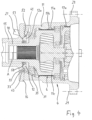
Fig. 3 : einen Längsschnitt durch die eine Hälfte der elektrischen Antriebsachse entlang einer inFig. 2 mit "III - III" bezeichneten, versetzten Schnittebene; -
Fig. 4 : einen vergrößerten Ausschnitt derFig. 3 . -
Fig. 3 zeigt in einem teilweisen Längsschnitt, der hier als Übersichtsdarstellung dient, die eine Hälfte einer elektrischen Antriebsachse für ein Kraftfahrzeug. Die dargestellte Hälfte der Antriebsachse dient dem Antrieb eines auf einem Achsschenkel 1 drehbar gelagerten, inFig. 3 am linken Rand gestrichelt dargestellten Fahrzeugrades 2. Die ebenso gestaltete zweite Hälfte der Antriebsachse befindet sich symmetrisch auf der anderen Seite der inFig. 3 eingetragenen Fahrzeugmittelebene M, und trägt das jeweilige Fahrzeugrad der anderen Fahrzeugseite. Die elektrische Antriebsachse ist in ihrer Gesamtheit eine von der einen bis zur anderen Fahrzeugseite durchgehende Starrachse. - Für jede Fahrzeugseite und damit zum Antrieb des jeweiligen Fahrzeugrades 2 ist nahe der Fahrzeugmittelebene M ein Elektroantrieb 5 vorgesehen, insbesondere ein Elektromotor. Jedem Elektromotor nach fahrzeugaußen nachgeschaltet ist jeweils ein Getriebe 6, hier in der Bauart eines zweistufigen Planetengetriebes.
- Die zwei Elektroantriebe 5 und zwei Getriebe 6 der elektrischen Antriebseinheit befinden sich in einem Antriebsgehäuse 4, welches ein- oder mehrteilig sein kann. Bei der hier beschriebenen Ausführungsform besteht das Antriebsgehäuse 4 aus drei Teilen bzw. Abschnitten, wobei sich beide Elektroantriebe 5 in einem gemeinsamen Antriebsgehäuseteil befinden, und jedes der beiden Getriebe 6 in einem weiteren, eigenen Antriebsgehäuseteil. Alternativ kann für jede Fahrzeugseite der Elektroantrieb 5 gemeinsam mit seinem Getriebe 6 in einem gemeinsamen Antriebsgehäuse 4 angeordnet sein.
- Das Antriebsgehäuse 4 ist also zugleich das Getriebegehäuse der Antriebseinheit und setzt sich zusammen aus einem im Wesentlichen zylindrischen Gehäusemantel 11, der mit seiner Innenseite 11a die Getriebeelemente des Getriebes 6 ringförmig umgibt, und aus einer einstückig mit dem Gehäusemantel 11 ausgebildeten Stirnwand 12. Die Stirnwand 12 ist überwiegend geschlossen, lässt jedoch in ihrem Zentrum eine Getriebeöffnung 17 frei, durch die die auf der zentralen Drehachse A rotierende Getriebeausgangswelle 18 des Getriebes 6 hindurchführt.
- Die Getriebeausgangswelle 18 kann, vorzugsweise über eine Keilverzahnung, drehfest mit einer Antriebswelle verbunden sein, welche zu dem Fahrzeugrad 2 führt und dieses antreibt. Anders als die Getriebeausgangswelle 18 ist die Antriebswelle nicht auf der Zeichnung dargestellt. Die Antriebswelle rotiert in einem rohrförmigen Achsgehäuse 15 der Antriebseinheit, welches sich auf der zentralen Achse A erstreckt. Das Achsgehäuse 15 ist an der Stirnseite des Antriebsgehäuses 4 befestigt.
- Das Achsgehäuse 15 der Antriebseinheit ist an seinem fahrzeugäußeren Ende mit dem Achsschenkel 1 versehen. Außerdem ist an dem Achsgehäuse 15 der Bremsträger der Fahrzeugbremse befestigt, vorzugsweise der Bremsträger einer Scheibenbremse. Ebenfalls an dem Achsgehäuse 15 befestigt ist ein Längslenker und ggf. ein Querlenker der Fahrzeugachse.
- Zur Befestigung des Achsgehäuses 15 an dem Antriebsgehäuse 4 ist das Achsgehäuse 15 an seinem fahrzeuginneren Ende mit einem radial erweiterten Flansch 16 versehen. Der Flansch 16 ist mittels mehrerer Schrauben 19 starr gegen die Stirnwand 12 des Antriebsgehäuses 4 verschraubt. Die Schrauben 19 stützen sich mit ihren Schraubenköpfen an dem Flansch 16 ab und greifen mit ihrem Gewinde in Gewindesacklöcher 20 ein, die in der Stirnwand 12 ausgebildet sind.
- Auch die Verbindung der Antriebsgehäuseteile, also des den Elektroantrieb 5 aufnehmenden Antriebsgehäuseteils einerseits und des das Getriebe 6 aufnehmenden Antriebsgehäuseteils andererseits, erfolgt mittels Verschraubungen 29, wozu die jeweiligen Enden dieser Antriebsgehäuseteile als Flansche gestaltet sind, die über die Verschraubungen 29 fest und vorzugsweise flüssigkeitsdicht miteinander verbunden sind. Sofern im Folgenden allgemein von dem Antriebsgehäuse 4 die Rede ist, ist damit jeweils jenes Antriebsgehäuseteil gemeint, in dem sich das Getriebe 6 und vorzugsweise zweistufige Planetengetriebe befindet.
- Das Antriebsgehäuse hat nicht nur die Gehäusefunktion, sondern es ist auch selbst Teil des Planetengetriebes, indem gemäß
Fig. 1 die Innenseite 11a des Gehäusemantels 11 eine um die Drehachse A herum angeordnete Schrägverzahnung 17a der ersten Getriebestufe, und axial versetzt eine um die Drehachse A herum angeordnete Schrägverzahnung 17b der zweiten Getriebestufe aufweist. Die Ausrichtung bzw. Schrägstellung der Zähne der Schrägverzahnung 17b ist entgegengesetzt zu den Zähnen der ersten Schrägverzahnung 17a. - Mit den innen an dem Gehäusemantel 11 ausgebildeten Schrägverzahnungen 17a, 17b kämmen die Planetenräder der beiden Getriebestufen des Planetengetriebes. Dessen übrige Getriebeelemente sind in einem auf der Achse A drehbaren Getriebeträger 17c angeordnet, der nach Art einer vormontierten Baueinheit in das Antriebsgehäuse 4 eingesetzt ist.
- Das Getriebe 6 ist von der Bauart eines Planetengetriebes. Die Planetenräder und Hohlräder des Planetengetriebes weisen eine Zahnschrägstellung auf, die eine von der Stirnwand 12 weg weisende Schaufelwirkung auf das Kühlmittel erzeugen, und die im Fall einer passiven Sumpfkühlung eine zu der Stirnwand 12 hin gerichtete Schaufelwirkung auf das Kühlmittel erzeugen.
- Der zentrale Teil des Getriebeträgers 17c ist die auf der Achse A drehende Getriebeausgangswelle 18, welche aus der ebenfalls zentral angeordneten Getriebeöffnung 17 des Antriebsgehäuses 4 herausragt und sich in das Achsgehäuse 15 hinein erstreckt.
- Die Kühlung des Getriebes 6 und dessen teils stark belasteter Zähne, Ritzel und Lager erfolgt im Fall einer aktiven Umlaufkühlung mittels der durch eine externe Pumpe umgewälzten Kühlflüssigkeit. Die Pumpe zieht die Flüssigkeit aus dem Antriebsgehäuse 4 ab, führt sie durch einen externen Wärmetauscher und fördert sie dann zu einem Anschlussstutzen 21, über den die Kühlflüssigkeit auf kurzem Wege in die Ringkammer 33 und damit zurück in den Kreislauf gelangt. Der Anschlussstutzen 21 befindet sich an dem Flansch 16 des Achsgehäuses 15.
- Im Falle der passiven Sumpfschmierung hingegen wird die Flüssigkeit ausschließlich innerhalb des Antriebsgehäuses 4 einschließlich der Ringkammer 33 umgewälzt, unter Verzicht auf eine externe Pumpe.
- Unabhängig von der Art der Umwälzung ist die Kühlflüssigkeit vorzugsweise ein Getriebeöl, so dass die Flüssigkeit sowohl die Getriebeelemente schmiert, als auch den Wärmeabtransport übernimmt.
- Bedingt durch die Bauart als Planetengetriebe wird Kühl- und Schmierflüssigkeit infolge von Zentrifugalkräften von den Planetenrädern nach außen gegen die Schrägverzahnungen 17a, 17b geschleudert. Die Kühlflüssigkeit sammelt sich daher an der Innenseite 11a des Gehäusemantels 11. Die im Folgenden näher beschriebenen Maßnahmen dienen dazu, die sich so an der Innenseite 11a des Gehäusemantels 11 ansammelnde Flüssigkeit zurück in zentralere Bereiche des Getriebes 6 sowie in den Bereich von Wälzlagern zu transportieren, zum Beispiel zu den Wälzlager 31 der Getriebeausgangswelle 18.
- Zur Verbesserung des Kühlmitteltransports und der Kühlleistung ist außen an der Stirnwand 12 eine die zentrale Drehachse A und die Getriebeöffnung 17 in Gestalt eines vollständigen Rings umgebende Ringkammer 33 angeordnet, in der sich Kühlmittel zwecks weiterer Umwälzung sammeln kann. Zugleich sind in dem Übergangsbereich zwischen dem Gehäusemantel 11 und der Stirnwand 12 des Antriebsgehäuses mehrere Kühlmittelkanäle 35 ausgebildet, die, ausgehend von der Innenseite 11a des Gehäusemantels 11, in die Ringkammer 33 führen. Innen am Gehäusemantel 11 und insbesondere an den Schrägverzahnungen 17a, 17b angesammelte Flüssigkeit gelangt daher in einem ersten Schritt durch die Kühlmittelkanäle 35 in die Ringkammer 33, die somit einen Sammler für Kühlflüssigkeit bildet.
- Eine Ringkammer beansprucht Platz, welcher in dem sehr kompakt gestalteten Antriebsgehäuse 4 nicht zur Verfügung steht. Daher befindet sich die Ringkammer 33 außen an der dem Fahrzeugrad 2 zugewandten Stirnseite des Antriebsgehäuses 4. Vor allem wird die Ringkammer 33 nicht alleine durch das Antriebsgehäuse 4 selbst gebildet, sondern zu einem anderen Teil durch das Achsgehäuse 15. Dies wird erreicht, indem die Ringkammer 33 zu einem Teil durch eine in der Außenseite der Stirnwand 12 ausgebildete, ringförmige Rinne gebildet wird, und zu einem anderen Teil durch einen Ringbereich an der Stirnseite des Flansches 16. Der Ringbereich an der Stirnseite des Flansches 16 bildet also gemeinsam mit der in der Stirnwand 12 ausgebildeten Rinne die Ringkammer 33, so dass an der Kühlmittelführung und Umwälzung nicht nur Bauteile des Getriebes beteiligt sind, sondern auch andere Bauteile der Antriebseinheit, nämlich der Flansch 16 des Achsgehäuses 15.
- Das Umwälzen des Kühlmittels und die Verbesserung der Kühlleistung wird auf diese Weise unter Ausnutzung gerade der bauartbedingten Besonderheiten der elektrischen Antriebseinheit erreicht, da auch das Achsgehäuse 15 Bestandteil dieser Antriebseinheit ist.
- Damit die Ringkammer 33 als Sammler dienen kann, ist eine Vielzahl der genannten Kühlmittelkanäle 35 vorhanden, wobei die Kühlmittelkanäle 35 vorzugsweise gleichmäßig über den Umfang des runden Antriebsgehäuses 4 verteilt angeordnet sind.
- Die in der Ringkammer 33 gesammelte Kühlflüssigkeit gelangt über weitere Kühlmittelkanäle 41 zurück in das Innere des Antriebsgehäuses 4. Die weiteren Kühlmittelkanäle 41 sind ebenfalls in einer Vielzahl vorhanden und gleichmäßig über den Umfang des runden Antriebsgehäuses 4 verteilt angeordnet. Sie führen von der Ringkammer 33 durch die Stirnwand 12 hindurch und münden jeweils an der Innenseite 12a der Stirnwand 12.
- Bei dem hier beschriebenen Ausführungsbeispiel sind die weiteren Kühlmittelkanäle 41 jeweils Durchgangsbohrungen, welche sich parallel zu der Drehachse A der Getriebeausgangswelle 18 erstrecken. In Bezug auf die Drehachse A sind die weiteren Kühlmittelkanäle 41 auf einem Durchmesser angeordnet, der geringer ist als der Durchmesser, auf dem die Kühlmittelkanäle 35 angeordnet sind.
- Um das im Bereich der Innenseite 11a angesammelte Kühlmedium in die Ringkammer 33 zu transportieren, verlaufen die Kühlmittelkanäle 35 unter einer Neigung zu der zentralen Achse A der Antriebseinheit. Die Einmündung jedes Kühlmittelkanals 35 in das Innere des Antriebsgehäuses 4 befindet sich radial weiter außen, als die Einmündung jedes Kühlmittelkanals 35 in die Ringkammer 33.
- Gemäß
Fig. 2 ist die Einmündung der Kühlmittelkanäle 35 einerseits und der weiteren Kühlmittelkanäle 41 andererseits in die rinnenförmige Ringkammer 33 dergestalt, dass die weiteren Kühlmittelkanäle 41 am Boden 42 der Ringkammer 33, und die Kühlmittelkanäle 35 in einer schräg zum Boden 42 angeordneten Seitenwand 43 der Ringkammer 33 münden. Bei dem Ausführungsbeispiel ist die Seitenwand 43 der Rinne, in die die Kühlmittelkanäle 35 münden, schräg zum Boden 42 der Rinne angeordnet, hingegen ist die andere Seitenwand im Wesentlichen senkrecht zum Boden 42 der Rinne angeordnet. Durch diese Ausgestaltung wird eine gleichmäßige Kühlmittelverteilung innerhalb der Ringkammer 33 erzielt. - Die Ringkammer 33 ist über eine erste Abdichtung 51 nach radial innen, und über eine zweite Abdichtung 52 nach radial außen abgedichtet, so dass weder nach innen, noch nach außen Flüssigkeit austreten kann. Vorzugsweise sind beide Abdichtungen 51, 52 um die zentrale Achse A herum angeordnete Ringdichtungen. Die Nut zur Aufnahme der jeweiligen Ringdichtung ist in der Stirnseite der Stirnwand 12 ausgebildet.
- Die Stirnwand 12 und der Flansch 16 sind durch an ihnen ausgebildete und in gegenseitigem Kontakt stehende Zentrierflächen 55 axial zueinander ausgerichtet. Die Zentrierflächen in Gestalt einer in Ringform um die zentrale Achse A verlaufenden Stufe sind auf einem Durchmesser angeordnet, der geringer ist als der geringste Durchmesser der Ringkammer 33. Die ringförmigen Zentrierflächen 55 befinden sich also radial zwischen der Ringkammer 33 und der inneren, ersten Abdichtung 51.
- Die den Flansch 16 an der Stirnwand 12 befestigenden, auf einem einheitlichen Teilkreis angeordneten Schrauben 19 greifen mit ihrem Gewinde jeweils in ein Gewindesackloch 20 ein, welches in der Stirnwand 12 ausgebildet ist.
- Für eine insgesamt kompakte Bauweise sind die Gewindesacklöcher 20 einerseits und die Kühlmittelkanäle 35 auf unterschiedlichen Umfangsabschnitten angeordnet (
Fig. 2 ). Zum Beispiel kann sich in Umfangsrichtung jeweils eine Schraube 19 bzw. ihr Gewindesackloch 20 mit einem der Kühlmittelkanäle 35 abwechseln. Bevorzugt ist jedoch die Ausgestaltung nachFig. 2 , bei der die Anzahl der Kühlmittelkanäle 35 halb so groß ist wie die Anzahl der Schrauben 19 bzw. Gewindesacklöcher 20. - Gemäß
Fig. 4 sind die weiteren Kühlmittelkanäle 41 so ausgerichtet, dass das aus ihnen austretende Kühlmittel nahezu auf direktem Wege zu jenem Wälzlager 31 gelangt, welches die Getriebeausgangswelle 18 in dem Gehäusemantel 11 lagert. Dies verbessert die Kühlung wie auch die Schmierung gerade dieses stark belasteten Wälzlagers 31. - Die radiale Abdichtung der Getriebeausgangswelle 18 gegenüber der umgebenden Getriebeöffnung 17 erfolgt mittels eines zwischen diesen Bauteilen angeordneten Radialwellendichtrings 58.
-
- 1 : Achsschenkel
- 2 : Fahrzeugrad
- 4 : Antriebsgehäuse
- 5 : Elektroantrieb
- 6 : Getriebe
- 11 : Gehäusemantel
- 11a : Innenseite Gehäusemantel
- 12 : Stirnwand
- 12a : Innenseite Stirnwand
- 15 : Achsgehäuse
- 16: Flansch
- 17: Getriebeöffnung
- 17a : Schrägverzahnung
- 17b : Schrägverzahnung
- 17c : Getriebeträger
- 18: Getriebeausgangswelle
- 19 : Schraube
- 20 : Gewindesackloch
- 21 : Anschlussstutzen
- 29 : Verschraubung
- 31 : Wälzlager
- 33: Ringkammer
- 35: Kühlmittelkanal
- 41 : Kühlmittelkanal
- 42: Boden
- 43 : Seitenwand
- 51 : erste Abdichtung, Ringdichtung
- 52 : zweite Abdichtung, Ringdichtung
- 55 : Zentrierflächen
- 58: Radialwellenabdichtung
- A : zentrale Achse, Drehachse
- M : Fahrzeugmittelebene
Claims (17)
- Elektrische Antriebseinheit für ein Kraftfahrzeug, mit einem Elektroantrieb (5), einem dem Elektroantrieb (5) nachgeschalteten, mehrstufigen Getriebe (6), welches allein oder zusammen mit dem Elektroantrieb (5) in einem Antriebsgehäuse (4) angeordnet ist, das sich zusammensetzt aus einem Gehäusemantel (11), der mit seiner Innenseite (11a) das Getriebe (6) ringförmig umgibt, und einer einstückig mit dem Gehäusemantel (11) ausgebildeten Stirnwand (12), die zentral mit einer Getriebeöffnung (17) für die Getriebeausgangswelle (18) des Getriebes (6) versehen ist, wobei zur Kühlung der Bauteile des Getriebes (6) Kühlflüssigkeit durch das Antriebsgehäuse (4) geleitet wird, wobei eine Ringkammer (33) außen an der Stirnwand (12) um die Getriebeöffnung (17) herum angeordnete ist, wobei in dem Antriebsgehäuse (4) Kühlmittelkanäle (35) ausgebildet sind, die ausgehend von der Innenseite (11 a) des Gehäusemantels (11) in die Ringkammer (33) führen, gekennzeichnet durch ein die Getriebeausgangswelle (18) umschließendes Achsgehäuse (15), welches dem Antriebsgehäuse (4) zugewandt mit einem Flansch (16) versehen ist, der an der Stirnwand (12) befestigt ist, wobei ein Ringbereich des Flansches (16) gemeinsam mit der Rinne die Ringkammer (33) bildet.
- Elektrische Antriebseinheit nach Anspruch 1, dadurch gekennzeichnet, dass die Ringkammer (33) teilweise durch eine Rinne in der Außenseite der Stirnwand (12) gebildet wird.
- Elektrische Antriebseinheit nach Anspruch 1 oder 2, dadurch gekennzeichnet, dass das Achsgehäuse (15) an seinem dem Flansch (16) abgewandten Ende mit einem Achsschenkel (1) zur Lagerung eines Fahrzeugrades (2) versehen ist.
- Elektrische Antriebseinheit nach einem der vorangehenden Ansprüche, dadurch gekennzeichnet, dass an dem Flansch (16) ein Kühlmittel-Anschlussstutzen angeordnet ist, und dass ein Kühlmittelkanal von dem Kühlmittel-Anschlussstutzen in die Ringkammer (33) führt.
- Elektrische Antriebseinheit nach einem der vorangehenden Ansprüche, gekennzeichnet durcheine erste und eine zweite Abdichtung zwischen dem Flansch und der Stirnwand (12), wobei die erste Abdichtung eine zwischen der Ringkammer (33) und der Getriebeöffnung (17) angeordnete Ringdichtung (51), und die zweite Abdichtung eine um die Ringkammer (33) herum angeordnete Ringdichtung (52) ist.
- Elektrische Antriebseinheit nach Anspruch 5, dadurch gekennzeichnet, dass die Ringdichtungen (51, 52) in zu der Außenseite der Stirnwand (12) hin offenen Ringnuten in der Stirnwand (12) sitzen.
- Elektrische Antriebseinheit nach Anspruch 5 oder 6, dadurch gekennzeichnet, dass die beiden Abdichtungen (51, 52) in Längsrichtung der Getriebeausgangswelle (18) axial zueinander versetzt angeordnet sind, wobei die zweite Abdichtung (52) die näher antriebsseitige Abdichtung ist.
- Elektrische Antriebseinheit nach einem der vorangehenden Ansprüche, dadurch gekennzeichnet, dass in dem Antriebsgehäuse (4) weitere Kühlmittelkanäle (41) ausgebildet sind, und dass die weiteren Kühlmittelkanäle (41) von der Ringkammer (33) durch die Stirnwand (12) hindurch bis an deren Innenseite (12a) führen.
- Elektrische Antriebseinheit nach Anspruch 8, dadurch gekennzeichnet, dass die weiteren Kühlmittelkanäle (41) Bohrungen sind, die in Bezug auf die zentrale Achse (A) auf einem Durchmesser angeordnet sind, der geringer ist als der Durchmesser, auf dem die Kühlmittelkanäle (35) angeordnet sind.
- Elektrische Antriebseinheit nach Anspruch 8 oder 9, dadurch gekennzeichnet, dass die Achsen der weiteren Kühlmittelkanäle (41) parallel zu der zentralen Achse (A) ausgerichtet sind.
- Elektrische Antriebseinheit nach einem der Ansprüche 8 - 10, dadurch gekennzeichnet, dass die weiteren Kühlmittelkanäle (41) an dem Boden (42), und dass die Kühlmittelkanäle (35) in der Seitenwand (43) der als Rinne ausgebildeten Ringkammer (33) münden.
- Elektrische Antriebseinheit nach einem der vorangehenden Ansprüche, dadurch gekennzeichnet, dass der Flansch (16) des Achsgehäuses (15) mittels einer Mehrzahl auf einem gemeinsamen Teilkreis angeordneter Schrauben (19) an der Stirnwand (12) befestigt ist.
- Elektrische Antriebseinheit nach Anspruch 12, dadurch gekennzeichnet, dass der Durchmesser des Teilkreises größer ist als der größte Durchmesser der Ringkammer (33), und vorzugsweise größer als der Durchmesser der zweiten Abdichtung (52).
- Elektrische Antriebseinheit nach Anspruch 12 oder 13 dadurch gekennzeichnet, dass die Schrauben (19) mit ihrem Gewinde in Gewindesacklöcher (20) engreifen, die in der Stirnwand (12) ausgebildet sind.
- Elektrische Antriebseinheit nach Anspruch 14, dadurch gekennzeichnet, dass die Kühlmittelkanäle (35) auf solchen Umfangsabschnitten in die Ringkammer (33) führen, auf denen in der Stirnwand (12) keine Gewindesacklöcher (20) ausgebildet sind.
- Elektrische Antriebseinheit nach einem der Ansprüche 12 - 15, dadurch gekennzeichnet, dass die Stirnwand (12) und der Flansch (16) durch an ihnen ausgebildete und in gegenseitigem Kontakt stehende Zentrierflächen (55) axial zueinander ausgerichtet sind.
- Elektrische Antriebseinheit nach Anspruch 16, dadurch gekennzeichnet, dass die Zentrierflächen (55) auf einem Durchmesser angeordnet sind, der geringer ist als der geringste Durchmesser der Ringkammer (33).
Applications Claiming Priority (2)
| Application Number | Priority Date | Filing Date | Title |
|---|---|---|---|
| DE102019118958.6A DE102019118958A1 (de) | 2019-07-12 | 2019-07-12 | Elektrische Antriebseinheit für ein Kraftfahrzeug |
| PCT/DE2020/100594 WO2021008653A1 (de) | 2019-07-12 | 2020-07-07 | Elektrische antriebseinheit für ein kraftfahrzeug |
Publications (2)
| Publication Number | Publication Date |
|---|---|
| EP3996943A1 EP3996943A1 (de) | 2022-05-18 |
| EP3996943B1 true EP3996943B1 (de) | 2025-05-14 |
Family
ID=71833094
Family Applications (1)
| Application Number | Title | Priority Date | Filing Date |
|---|---|---|---|
| EP20746549.3A Active EP3996943B1 (de) | 2019-07-12 | 2020-07-07 | Elektrische antriebseinheit für ein kraftfahrzeug |
Country Status (8)
| Country | Link |
|---|---|
| US (1) | US11940044B2 (de) |
| EP (1) | EP3996943B1 (de) |
| JP (1) | JP7566866B2 (de) |
| CN (1) | CN114174100B (de) |
| AU (1) | AU2020312542B2 (de) |
| DE (1) | DE102019118958A1 (de) |
| ES (1) | ES3030909T3 (de) |
| WO (1) | WO2021008653A1 (de) |
Families Citing this family (4)
| Publication number | Priority date | Publication date | Assignee | Title |
|---|---|---|---|---|
| DE102019118958A1 (de) * | 2019-07-12 | 2021-01-14 | Bpw Bergische Achsen Kommanditgesellschaft | Elektrische Antriebseinheit für ein Kraftfahrzeug |
| DE102021118698A1 (de) * | 2021-07-20 | 2023-01-26 | Bpw Bergische Achsen Kommanditgesellschaft | Fahrzeugachse |
| DE102023101454A1 (de) | 2023-01-20 | 2024-07-25 | Gigant Gmbh | Nutzfahrzeug mit elektrischem Antriebsmotor |
| DE102023112357A1 (de) | 2023-05-10 | 2024-11-14 | Gigant Gmbh | Nutzfahrzeugtrailer mit elektrischem Antriebsmotor |
Family Cites Families (23)
| Publication number | Priority date | Publication date | Assignee | Title |
|---|---|---|---|---|
| US4418777A (en) * | 1981-09-11 | 1983-12-06 | Ford Motor Company | Transmission lubrication and motor cooling system |
| JP2962071B2 (ja) * | 1992-09-11 | 1999-10-12 | トヨタ自動車株式会社 | 電気自動車用駆動装置 |
| US5519269A (en) * | 1994-06-10 | 1996-05-21 | Westinghouse Electric Corp. | Electric induction motor and related method of cooling |
| AT405924B (de) * | 1998-01-16 | 1999-12-27 | Oskar Wachauer | Antrieb für ein fahrzeug, insbesondere für ein mehrspuriges elektromobil |
| JP2004180477A (ja) | 2002-11-29 | 2004-06-24 | Honda Motor Co Ltd | 前後輪駆動車両におけるモータの冷却構造 |
| DE102004004617A1 (de) * | 2004-01-29 | 2005-09-08 | Magnet-Motor Gesellschaft Für Magnetmotorische Technik Mbh | Elektrische Antriebseinheit für ein Kraftfahrzeug |
| DE102005022926B3 (de) * | 2005-05-13 | 2007-02-01 | Getrag Innovations Gmbh | Antriebseinheit für ein Kraftfahrzeug |
| JP4867491B2 (ja) | 2005-07-28 | 2012-02-01 | トヨタ自動車株式会社 | 駆動装置およびこれを搭載する自動車 |
| EP1956272B1 (de) * | 2007-02-07 | 2010-01-20 | Nissan Motor Company Limited | Getriebeeinheit und Verfahren zur Vermeidung von Schmierölspritzern |
| US8931596B2 (en) * | 2010-02-04 | 2015-01-13 | Toyota Jidosha Kabushiki Kaisha | Lubricant oil supplying apparatus |
| FR2962079B1 (fr) * | 2010-07-01 | 2012-07-27 | Michelin Soc Tech | Moyeu motorise comprenant une machine electrique de traction. |
| WO2013029682A1 (de) * | 2011-09-01 | 2013-03-07 | Schaeffler Technologies AG & Co. KG | Antriebsvorrichtung |
| WO2013050182A1 (de) * | 2011-10-05 | 2013-04-11 | Schaeffler Technologies AG & Co. KG | Elektromotorische getriebevorrichtung |
| DE102012112379A1 (de) * | 2012-12-17 | 2014-06-18 | Linde Material Handling Gmbh | Antriebsachse mit zumindest einem elektrischen Fahrmotor |
| JP6301125B2 (ja) | 2013-12-17 | 2018-03-28 | Ntn株式会社 | インホイールモータ駆動装置 |
| JP2016070358A (ja) * | 2014-09-30 | 2016-05-09 | Ntn株式会社 | インホイールモータ駆動装置の潤滑装置 |
| PL3213392T3 (pl) * | 2014-10-31 | 2021-05-31 | Gkn Automotive Limited | Napęd elektryczny |
| US9400034B1 (en) * | 2015-08-12 | 2016-07-26 | Borgwarner Inc. | Electric drive system |
| DE102015216975B4 (de) * | 2015-09-04 | 2021-02-04 | Schaeffler Technologies AG & Co. KG | Getriebevorrichtung sowie elektrische Antriebseinheit mit wenigstens einer elektrischen Maschine und mit der Getriebevorrichtung |
| DE102016209549A1 (de) * | 2016-06-01 | 2017-12-07 | Voith Patent Gmbh | Stirnradgetriebe |
| DE102017106927B4 (de) * | 2017-03-30 | 2018-11-29 | Zollern Gmbh & Co. Kg | Getriebe mit einem Schmiersystem und einer Fördereinrichtung |
| DE102019118958A1 (de) * | 2019-07-12 | 2021-01-14 | Bpw Bergische Achsen Kommanditgesellschaft | Elektrische Antriebseinheit für ein Kraftfahrzeug |
| DE102019118967A1 (de) * | 2019-07-12 | 2021-01-14 | Bpw Bergische Achsen Kg | Elektrische Antriebseinheit für ein Kraftfahrzeug |
-
2019
- 2019-07-12 DE DE102019118958.6A patent/DE102019118958A1/de active Pending
-
2020
- 2020-07-07 US US17/626,522 patent/US11940044B2/en active Active
- 2020-07-07 EP EP20746549.3A patent/EP3996943B1/de active Active
- 2020-07-07 WO PCT/DE2020/100594 patent/WO2021008653A1/de not_active Ceased
- 2020-07-07 ES ES20746549T patent/ES3030909T3/es active Active
- 2020-07-07 AU AU2020312542A patent/AU2020312542B2/en active Active
- 2020-07-07 JP JP2022501340A patent/JP7566866B2/ja active Active
- 2020-07-07 CN CN202080050681.6A patent/CN114174100B/zh active Active
Also Published As
| Publication number | Publication date |
|---|---|
| US11940044B2 (en) | 2024-03-26 |
| AU2020312542B2 (en) | 2025-02-06 |
| WO2021008653A1 (de) | 2021-01-21 |
| DE102019118958A1 (de) | 2021-01-14 |
| JP2022540239A (ja) | 2022-09-14 |
| EP3996943A1 (de) | 2022-05-18 |
| AU2020312542A1 (en) | 2022-02-03 |
| US20220228658A1 (en) | 2022-07-21 |
| CN114174100A (zh) | 2022-03-11 |
| JP7566866B2 (ja) | 2024-10-15 |
| ES3030909T3 (en) | 2025-07-02 |
| CN114174100B (zh) | 2024-04-30 |
Similar Documents
| Publication | Publication Date | Title |
|---|---|---|
| EP3996943B1 (de) | Elektrische antriebseinheit für ein kraftfahrzeug | |
| EP2412083B1 (de) | Antriebseinrichtung | |
| DE102012207498A1 (de) | Stirnraddifferential | |
| DE112018004102T5 (de) | Elektrisches Antriebsmodul mit einem Motor mit einem Kühlkörpereinsatz in einer Rotorwelle | |
| EP3969307B1 (de) | Elektrische antriebseinheit für ein kraftfahrzeug | |
| EP0688090B1 (de) | Kühlsystem für einen Motor | |
| WO2012139820A2 (de) | Antriebsvorrichtung mit einer kühlbaren rotoranordnung | |
| DE112019002167T5 (de) | Fahrzeugantriebseinheit | |
| DE69311484T3 (de) | Getriebe mit integrierter Bremse insbesondere für Fahrzeuge | |
| EP0949419B1 (de) | Innenzahnradmaschine | |
| DE102018205862A1 (de) | Getriebe, insbesondere für eine Einzelradantriebseinheit | |
| EP2255104B1 (de) | Getriebe | |
| EP2665938B1 (de) | Elektrische fluidpumpe mit gekühltem nasslaufbereich | |
| WO2015003706A1 (de) | Lageranordnung für ein planetengetriebe einer windkraftanlage | |
| DE102017204451A1 (de) | Getriebe, insbesondere für Antriebsstrang von Schienenfahrzeugen | |
| EP0337950A2 (de) | Innenachsige Rotationskolbenmaschine | |
| EP3996944B1 (de) | Elektrische antriebseinheit für ein kraftfahrzeug | |
| DE102016224898A1 (de) | Pumpeneinrichtung für ein Automatikgetriebe | |
| DE102017106942A1 (de) | Hydrodynamische Kupplung | |
| DE102020105798A1 (de) | Bremsvorrichtung | |
| EP3441613B1 (de) | Hydrostatische zahnrad-kreiskolbenmaschine | |
| DE102021132595B4 (de) | Elektrisches Antriebssystem mit zwei Antriebsmaschinen und gehäuseseitiger Statorverschraubung | |
| DE102017119497A1 (de) | Fluiddynamisches Lagersystem | |
| DE102017010372A1 (de) | Antrieb, aufweisend ein über ein Summiergetriebe von Elektromotoren antreibbares Getriebe | |
| WO2023174888A1 (de) | Ölpumpe für ein kraftfahrzeug |
Legal Events
| Date | Code | Title | Description |
|---|---|---|---|
| STAA | Information on the status of an ep patent application or granted ep patent |
Free format text: STATUS: UNKNOWN |
|
| STAA | Information on the status of an ep patent application or granted ep patent |
Free format text: STATUS: THE INTERNATIONAL PUBLICATION HAS BEEN MADE |
|
| PUAI | Public reference made under article 153(3) epc to a published international application that has entered the european phase |
Free format text: ORIGINAL CODE: 0009012 |
|
| STAA | Information on the status of an ep patent application or granted ep patent |
Free format text: STATUS: REQUEST FOR EXAMINATION WAS MADE |
|
| 17P | Request for examination filed |
Effective date: 20211214 |
|
| AK | Designated contracting states |
Kind code of ref document: A1 Designated state(s): AL AT BE BG CH CY CZ DE DK EE ES FI FR GB GR HR HU IE IS IT LI LT LU LV MC MK MT NL NO PL PT RO RS SE SI SK SM TR |
|
| DAV | Request for validation of the european patent (deleted) | ||
| DAX | Request for extension of the european patent (deleted) | ||
| STAA | Information on the status of an ep patent application or granted ep patent |
Free format text: STATUS: EXAMINATION IS IN PROGRESS |
|
| 17Q | First examination report despatched |
Effective date: 20240905 |
|
| GRAP | Despatch of communication of intention to grant a patent |
Free format text: ORIGINAL CODE: EPIDOSNIGR1 |
|
| STAA | Information on the status of an ep patent application or granted ep patent |
Free format text: STATUS: GRANT OF PATENT IS INTENDED |
|
| INTG | Intention to grant announced |
Effective date: 20241118 |
|
| GRAJ | Information related to disapproval of communication of intention to grant by the applicant or resumption of examination proceedings by the epo deleted |
Free format text: ORIGINAL CODE: EPIDOSDIGR1 |
|
| STAA | Information on the status of an ep patent application or granted ep patent |
Free format text: STATUS: EXAMINATION IS IN PROGRESS |
|
| GRAS | Grant fee paid |
Free format text: ORIGINAL CODE: EPIDOSNIGR3 |
|
| STAA | Information on the status of an ep patent application or granted ep patent |
Free format text: STATUS: GRANT OF PATENT IS INTENDED |
|
| GRAP | Despatch of communication of intention to grant a patent |
Free format text: ORIGINAL CODE: EPIDOSNIGR1 |
|
| GRAA | (expected) grant |
Free format text: ORIGINAL CODE: 0009210 |
|
| STAA | Information on the status of an ep patent application or granted ep patent |
Free format text: STATUS: THE PATENT HAS BEEN GRANTED |
|
| INTC | Intention to grant announced (deleted) | ||
| P01 | Opt-out of the competence of the unified patent court (upc) registered |
Free format text: CASE NUMBER: APP_12999/2025 Effective date: 20250317 |
|
| INTG | Intention to grant announced |
Effective date: 20250403 |
|
| AK | Designated contracting states |
Kind code of ref document: B1 Designated state(s): AL AT BE BG CH CY CZ DE DK EE ES FI FR GB GR HR HU IE IS IT LI LT LU LV MC MK MT NL NO PL PT RO RS SE SI SK SM TR |
|
| REG | Reference to a national code |
Ref country code: GB Ref legal event code: FG4D Free format text: NOT ENGLISH |
|
| REG | Reference to a national code |
Ref country code: CH Ref legal event code: EP |
|
| REG | Reference to a national code |
Ref country code: DE Ref legal event code: R096 Ref document number: 502020011061 Country of ref document: DE |
|
| REG | Reference to a national code |
Ref country code: IE Ref legal event code: FG4D Free format text: LANGUAGE OF EP DOCUMENT: GERMAN |
|
| REG | Reference to a national code |
Ref country code: ES Ref legal event code: FG2A Ref document number: 3030909 Country of ref document: ES Kind code of ref document: T3 Effective date: 20250702 |
|
| REG | Reference to a national code |
Ref country code: NL Ref legal event code: MP Effective date: 20250514 |
|
| PG25 | Lapsed in a contracting state [announced via postgrant information from national office to epo] |
Ref country code: PT Free format text: LAPSE BECAUSE OF FAILURE TO SUBMIT A TRANSLATION OF THE DESCRIPTION OR TO PAY THE FEE WITHIN THE PRESCRIBED TIME-LIMIT Effective date: 20250915 Ref country code: FI Free format text: LAPSE BECAUSE OF FAILURE TO SUBMIT A TRANSLATION OF THE DESCRIPTION OR TO PAY THE FEE WITHIN THE PRESCRIBED TIME-LIMIT Effective date: 20250514 |
|
| PGFP | Annual fee paid to national office [announced via postgrant information from national office to epo] |
Ref country code: ES Payment date: 20250819 Year of fee payment: 6 |
|
| PGFP | Annual fee paid to national office [announced via postgrant information from national office to epo] |
Ref country code: DE Payment date: 20250916 Year of fee payment: 6 |
|
| REG | Reference to a national code |
Ref country code: LT Ref legal event code: MG9D |
|
| PG25 | Lapsed in a contracting state [announced via postgrant information from national office to epo] |
Ref country code: GR Free format text: LAPSE BECAUSE OF FAILURE TO SUBMIT A TRANSLATION OF THE DESCRIPTION OR TO PAY THE FEE WITHIN THE PRESCRIBED TIME-LIMIT Effective date: 20250815 Ref country code: NO Free format text: LAPSE BECAUSE OF FAILURE TO SUBMIT A TRANSLATION OF THE DESCRIPTION OR TO PAY THE FEE WITHIN THE PRESCRIBED TIME-LIMIT Effective date: 20250814 |
|
| PG25 | Lapsed in a contracting state [announced via postgrant information from national office to epo] |
Ref country code: NL Free format text: LAPSE BECAUSE OF FAILURE TO SUBMIT A TRANSLATION OF THE DESCRIPTION OR TO PAY THE FEE WITHIN THE PRESCRIBED TIME-LIMIT Effective date: 20250514 Ref country code: PL Free format text: LAPSE BECAUSE OF FAILURE TO SUBMIT A TRANSLATION OF THE DESCRIPTION OR TO PAY THE FEE WITHIN THE PRESCRIBED TIME-LIMIT Effective date: 20250514 |
|
| PGFP | Annual fee paid to national office [announced via postgrant information from national office to epo] |
Ref country code: TR Payment date: 20250807 Year of fee payment: 6 Ref country code: IT Payment date: 20250904 Year of fee payment: 6 |
|
| PG25 | Lapsed in a contracting state [announced via postgrant information from national office to epo] |
Ref country code: BG Free format text: LAPSE BECAUSE OF FAILURE TO SUBMIT A TRANSLATION OF THE DESCRIPTION OR TO PAY THE FEE WITHIN THE PRESCRIBED TIME-LIMIT Effective date: 20250514 |
|
| PGFP | Annual fee paid to national office [announced via postgrant information from national office to epo] |
Ref country code: GB Payment date: 20250716 Year of fee payment: 6 |
|
| PG25 | Lapsed in a contracting state [announced via postgrant information from national office to epo] |
Ref country code: HR Free format text: LAPSE BECAUSE OF FAILURE TO SUBMIT A TRANSLATION OF THE DESCRIPTION OR TO PAY THE FEE WITHIN THE PRESCRIBED TIME-LIMIT Effective date: 20250514 |
|
| PGFP | Annual fee paid to national office [announced via postgrant information from national office to epo] |
Ref country code: FR Payment date: 20250723 Year of fee payment: 6 |
|
| PG25 | Lapsed in a contracting state [announced via postgrant information from national office to epo] |
Ref country code: RS Free format text: LAPSE BECAUSE OF FAILURE TO SUBMIT A TRANSLATION OF THE DESCRIPTION OR TO PAY THE FEE WITHIN THE PRESCRIBED TIME-LIMIT Effective date: 20250814 |
|
| PG25 | Lapsed in a contracting state [announced via postgrant information from national office to epo] |
Ref country code: IS Free format text: LAPSE BECAUSE OF FAILURE TO SUBMIT A TRANSLATION OF THE DESCRIPTION OR TO PAY THE FEE WITHIN THE PRESCRIBED TIME-LIMIT Effective date: 20250914 |
|
| PG25 | Lapsed in a contracting state [announced via postgrant information from national office to epo] |
Ref country code: LV Free format text: LAPSE BECAUSE OF FAILURE TO SUBMIT A TRANSLATION OF THE DESCRIPTION OR TO PAY THE FEE WITHIN THE PRESCRIBED TIME-LIMIT Effective date: 20250514 |
|
| PG25 | Lapsed in a contracting state [announced via postgrant information from national office to epo] |
Ref country code: SM Free format text: LAPSE BECAUSE OF FAILURE TO SUBMIT A TRANSLATION OF THE DESCRIPTION OR TO PAY THE FEE WITHIN THE PRESCRIBED TIME-LIMIT Effective date: 20250514 Ref country code: DK Free format text: LAPSE BECAUSE OF FAILURE TO SUBMIT A TRANSLATION OF THE DESCRIPTION OR TO PAY THE FEE WITHIN THE PRESCRIBED TIME-LIMIT Effective date: 20250514 |
|
| PG25 | Lapsed in a contracting state [announced via postgrant information from national office to epo] |
Ref country code: CZ Free format text: LAPSE BECAUSE OF FAILURE TO SUBMIT A TRANSLATION OF THE DESCRIPTION OR TO PAY THE FEE WITHIN THE PRESCRIBED TIME-LIMIT Effective date: 20250514 |
|
| PG25 | Lapsed in a contracting state [announced via postgrant information from national office to epo] |
Ref country code: EE Free format text: LAPSE BECAUSE OF FAILURE TO SUBMIT A TRANSLATION OF THE DESCRIPTION OR TO PAY THE FEE WITHIN THE PRESCRIBED TIME-LIMIT Effective date: 20250514 |
|
| PG25 | Lapsed in a contracting state [announced via postgrant information from national office to epo] |
Ref country code: SK Free format text: LAPSE BECAUSE OF FAILURE TO SUBMIT A TRANSLATION OF THE DESCRIPTION OR TO PAY THE FEE WITHIN THE PRESCRIBED TIME-LIMIT Effective date: 20250514 Ref country code: RO Free format text: LAPSE BECAUSE OF FAILURE TO SUBMIT A TRANSLATION OF THE DESCRIPTION OR TO PAY THE FEE WITHIN THE PRESCRIBED TIME-LIMIT Effective date: 20250514 |
|
| REG | Reference to a national code |
Ref country code: DE Ref legal event code: R097 Ref document number: 502020011061 Country of ref document: DE |
|
| REG | Reference to a national code |
Ref country code: CH Ref legal event code: H13 Free format text: ST27 STATUS EVENT CODE: U-0-0-H10-H13 (AS PROVIDED BY THE NATIONAL OFFICE) Effective date: 20260224 |
|
| PG25 | Lapsed in a contracting state [announced via postgrant information from national office to epo] |
Ref country code: LU Free format text: LAPSE BECAUSE OF NON-PAYMENT OF DUE FEES Effective date: 20250707 |
|
| PLBE | No opposition filed within time limit |
Free format text: ORIGINAL CODE: 0009261 |
|
| STAA | Information on the status of an ep patent application or granted ep patent |
Free format text: STATUS: NO OPPOSITION FILED WITHIN TIME LIMIT |
|
| REG | Reference to a national code |
Ref country code: CH Ref legal event code: L10 Free format text: ST27 STATUS EVENT CODE: U-0-0-L10-L00 (AS PROVIDED BY THE NATIONAL OFFICE) Effective date: 20260325 |
|
| REG | Reference to a national code |
Ref country code: BE Ref legal event code: MM Effective date: 20250731 |
|
| PG25 | Lapsed in a contracting state [announced via postgrant information from national office to epo] |
Ref country code: BE Free format text: LAPSE BECAUSE OF NON-PAYMENT OF DUE FEES Effective date: 20250731 |
|
| 26N | No opposition filed |
Effective date: 20260217 |
|
| PG25 | Lapsed in a contracting state [announced via postgrant information from national office to epo] |
Ref country code: CH Free format text: LAPSE BECAUSE OF NON-PAYMENT OF DUE FEES Effective date: 20250731 |