EP3993151A2 - Batterie - Google Patents
Batterie Download PDFInfo
- Publication number
- EP3993151A2 EP3993151A2 EP21201188.6A EP21201188A EP3993151A2 EP 3993151 A2 EP3993151 A2 EP 3993151A2 EP 21201188 A EP21201188 A EP 21201188A EP 3993151 A2 EP3993151 A2 EP 3993151A2
- Authority
- EP
- European Patent Office
- Prior art keywords
- battery
- cell
- battery cells
- stack
- contacting
- Prior art date
- Legal status (The legal status is an assumption and is not a legal conclusion. Google has not performed a legal analysis and makes no representation as to the accuracy of the status listed.)
- Pending
Links
Images


Classifications
-
- H—ELECTRICITY
- H01—ELECTRIC ELEMENTS
- H01M—PROCESSES OR MEANS, e.g. BATTERIES, FOR THE DIRECT CONVERSION OF CHEMICAL ENERGY INTO ELECTRICAL ENERGY
- H01M50/00—Constructional details or processes of manufacture of the non-active parts of electrochemical cells other than fuel cells, e.g. hybrid cells
- H01M50/50—Current conducting connections for cells or batteries
- H01M50/502—Interconnectors for connecting terminals of adjacent batteries; Interconnectors for connecting cells outside a battery casing
- H01M50/503—Interconnectors for connecting terminals of adjacent batteries; Interconnectors for connecting cells outside a battery casing characterised by the shape of the interconnectors
-
- H—ELECTRICITY
- H01—ELECTRIC ELEMENTS
- H01M—PROCESSES OR MEANS, e.g. BATTERIES, FOR THE DIRECT CONVERSION OF CHEMICAL ENERGY INTO ELECTRICAL ENERGY
- H01M50/00—Constructional details or processes of manufacture of the non-active parts of electrochemical cells other than fuel cells, e.g. hybrid cells
- H01M50/20—Mountings; Secondary casings or frames; Racks, modules or packs; Suspension devices; Shock absorbers; Transport or carrying devices; Holders
- H01M50/204—Racks, modules or packs for multiple batteries or multiple cells
-
- H—ELECTRICITY
- H01—ELECTRIC ELEMENTS
- H01M—PROCESSES OR MEANS, e.g. BATTERIES, FOR THE DIRECT CONVERSION OF CHEMICAL ENERGY INTO ELECTRICAL ENERGY
- H01M50/00—Constructional details or processes of manufacture of the non-active parts of electrochemical cells other than fuel cells, e.g. hybrid cells
- H01M50/50—Current conducting connections for cells or batteries
- H01M50/502—Interconnectors for connecting terminals of adjacent batteries; Interconnectors for connecting cells outside a battery casing
- H01M50/507—Interconnectors for connecting terminals of adjacent batteries; Interconnectors for connecting cells outside a battery casing comprising an arrangement of two or more busbars within a container structure, e.g. busbar modules
-
- H—ELECTRICITY
- H01—ELECTRIC ELEMENTS
- H01M—PROCESSES OR MEANS, e.g. BATTERIES, FOR THE DIRECT CONVERSION OF CHEMICAL ENERGY INTO ELECTRICAL ENERGY
- H01M50/00—Constructional details or processes of manufacture of the non-active parts of electrochemical cells other than fuel cells, e.g. hybrid cells
- H01M50/50—Current conducting connections for cells or batteries
- H01M50/502—Interconnectors for connecting terminals of adjacent batteries; Interconnectors for connecting cells outside a battery casing
- H01M50/509—Interconnectors for connecting terminals of adjacent batteries; Interconnectors for connecting cells outside a battery casing characterised by the type of connection, e.g. mixed connections
-
- H—ELECTRICITY
- H01—ELECTRIC ELEMENTS
- H01M—PROCESSES OR MEANS, e.g. BATTERIES, FOR THE DIRECT CONVERSION OF CHEMICAL ENERGY INTO ELECTRICAL ENERGY
- H01M50/00—Constructional details or processes of manufacture of the non-active parts of electrochemical cells other than fuel cells, e.g. hybrid cells
- H01M50/50—Current conducting connections for cells or batteries
- H01M50/502—Interconnectors for connecting terminals of adjacent batteries; Interconnectors for connecting cells outside a battery casing
- H01M50/514—Methods for interconnecting adjacent batteries or cells
- H01M50/516—Methods for interconnecting adjacent batteries or cells by welding, soldering or brazing
-
- H—ELECTRICITY
- H01—ELECTRIC ELEMENTS
- H01M—PROCESSES OR MEANS, e.g. BATTERIES, FOR THE DIRECT CONVERSION OF CHEMICAL ENERGY INTO ELECTRICAL ENERGY
- H01M2220/00—Batteries for particular applications
- H01M2220/20—Batteries in motive systems, e.g. vehicle, ship, plane
-
- Y—GENERAL TAGGING OF NEW TECHNOLOGICAL DEVELOPMENTS; GENERAL TAGGING OF CROSS-SECTIONAL TECHNOLOGIES SPANNING OVER SEVERAL SECTIONS OF THE IPC; TECHNICAL SUBJECTS COVERED BY FORMER USPC CROSS-REFERENCE ART COLLECTIONS [XRACs] AND DIGESTS
- Y02—TECHNOLOGIES OR APPLICATIONS FOR MITIGATION OR ADAPTATION AGAINST CLIMATE CHANGE
- Y02E—REDUCTION OF GREENHOUSE GAS [GHG] EMISSIONS, RELATED TO ENERGY GENERATION, TRANSMISSION OR DISTRIBUTION
- Y02E60/00—Enabling technologies; Technologies with a potential or indirect contribution to GHG emissions mitigation
- Y02E60/10—Energy storage using batteries
Definitions
- the present invention relates to a battery, in particular a battery for an electrically powered means of transportation.
- Electrically driven two-wheelers and in particular electric bicycles, also known as e-bikes, are known from the prior art, which use batteries as the energy source for the electric drive, which are composed of a plurality of battery stacks comprising a plurality of battery cells. It is also known to arrange the individual battery cells within the battery stack in such a way that they can be placed in a space-saving arrangement in a tubular housing, which can be attached to a frame of such two-wheelers, for example. Such a design for batteries of electrically powered two-wheelers is also known as the "Powertube" design.
- the respective series and parallel circuits of battery cells in the battery are usually implemented directly via electrically conductive cell connectors, which are arranged on the respective contacting areas (poles) of the battery cells.
- a battery management system (BMS) and a connector plug of such batteries are usually arranged on the end faces of the battery (also called “core pack”). Therefore, both a serial power path, which is implemented via lines and/or overlapping contact lugs of the cell connectors, and a monitoring path for the individual cell potentials, which is implemented via cables or flexible printed circuit boards, must be routed to the front. For the resulting crossing points of the respective lines, special insulation measures must be taken in order to avoid an internal short circuit in the battery. In the case of higher battery capacities in particular, a correspondingly large number of crossing points can arise.
- the present invention proposes a battery which is in particular an energy source for an electrically powered means of transportation, preferably for an electrically powered two-wheeler and particularly preferably for an electrically powered bicycle.
- the battery according to the invention has a first cell stack comprising a first arrangement of battery cells, a second cell stack comprising a second arrangement of battery cells, a plurality of electrically conductive cell connectors and at least one electrically conductive stack connector.
- the battery cells are preferably designed in the form of round cells, the respective electrical poles of which are arranged on opposite sides of the battery cells.
- the battery cells within the respective cell stacks are arranged parallel to one another with respect to their respective direction of longitudinal extension, so that respective opposite electrical contacting regions (poles) of the battery cells are provided on a first contacting side and on a second contacting side of the respective cell stack. Furthermore, the first cell stack and the second cell stack are immovably connected to one another in such a way that one of the contacting sides of the first cell stack faces one of the contacting sides of the second cell stack, with mutually facing contacting areas of the battery cells of the respective cell stacks being spaced apart from one another.
- the contact areas of battery cells facing one another are not in direct contact.
- the electrical contact between the respective battery cells within a cell stack is established by the aforementioned cell connectors, which are arranged on the respective contacting sides of the cell stack and which electrically connect at least two battery cells per contacting side to one another (in parallel and/or in series) and this electrical connection by means of respective contact lugs in a first contacting section of the battery and/or provide in a second contacting section of the battery that differs from the first contacting section.
- the two contacting sections are to be understood in particular as sections of an outer surface of the battery that span the cell stack, in which the contact lugs of the respective cell connectors are arranged so that they are accessible from the outside.
- the at least one stack connector is designed as a single layer (ie it has no intersecting conductor tracks) and is set up to combine voltages provided by the contact lugs in the first contacting section of electrically connected battery cells at a power connection of the battery to form a total voltage of the battery.
- a position at which the overall voltage is provided by the at least one stack connector is preferably a position on one of the end faces of the battery, without being restricted to such a position.
- more than one electrically conductive stack connector is used, such a plurality of stack connectors being arranged one behind the other in the longitudinal direction of the battery and being electrically connected to one another.
- a number of electrically connected stack connectors is not limited to a specific number, and it is also possible for the individual stack connectors to be designed differently.
- the battery according to the invention provides that at least two adjacent contact lugs of the first cell stack and of the second cell stack are electrically connected to one another in the second contact section.
- the concept according to the invention creates a simple and, in terms of production, quick and cost-effective contacting option by connecting respective contact lugs in the first contacting section of the battery by means of the at least one stack connector. It should be pointed out in general that the number of two cell stacks of the battery according to the invention described here only represents a minimum number and that the battery can include further cell stacks in accordance with the above description.
- a number of battery cells of the battery within the first arrangement of battery cells and a number of battery cells within the second arrangement of battery cells are preferably identical.
- the alignments of respective poles of the battery cells within the first arrangement and within the second arrangement have at least one deviation between the first arrangement and the second arrangement.
- at least one battery cell of one cell stack is rotated by 180° with respect to the orientation of its poles to a battery cell of the other cell stack, which is in the same position within the second cell stack as the battery cell within the first cell stack.
- the battery according to the invention particularly advantageously has six cell stacks that are electrically connected to one another, with each cell stack having ten battery cells each, which are preferably arranged one above the other in three levels in a 3-4-3 arrangement (which is particularly space-saving), with six Battery cells are connected in parallel within a cell stack or across cell stacks, and each battery cell connected in parallel is connected in series to generate the total voltage of the battery. For this reason, such a connection of battery cells of the battery is also referred to as a "10s6p" arrangement, since six battery cells are connected in parallel and ten such parallel circuits are connected in series.
- the battery has three, four, five or more cell stacks, which preferably each comprise ten battery cells.
- the stack connector is preferably a stamped grid, in particular a stamped grid connected to a plastic holder.
- the plastic holder allows e.g. a stationary arrangement of a plurality of electrically isolated sections of the leadframe.
- a connection between the stamped grid and the plastic holder can be ensured, for example, by means of an adhesive connection and/or by means of an insert manufacturing process, through which the plastic holder and the stamped grid form a form-fitting connection.
- a suitable material for the pressed screen is, for example, copper or a different electrically conductive material.
- the stack connector is set up to electrically connect contact lugs within a cell stack and/or contact lugs of different cell stacks to one another. If a plurality of stack connectors are used within the first contacting section of the battery, it is also conceivable to connect the respective stack connectors directly to one another and/or to connect them to one another via the contact lugs of the cell connectors. Alternatively, it is also possible to electrically connect the respective stack connectors to one another by means of further connecting elements.
- the contact lugs of the cell connectors are designed to be bent over onto a contact lug of a respectively adjacent cell stack in such a way that the two contact lugs overlap.
- that part of the contact lugs which is bent onto the respectively adjacent contact lugs has a greater length than the respectively adjacent contact lugs. This explicitly does not rule out that all contact lugs have an identical length.
- the contact lugs are designed to be electrically connected to respectively adjacent contact lugs, this connection being in particular a welded and/or soldered connection.
- the battery is set up particularly advantageously via the contact lugs of the cell connectors in the second contacting section Provide partial voltages of respective battery cells connected in parallel.
- This offers the advantage that, for example, all individual potentials can be monitored by means of access via the contact lugs in the second contacting section. Such monitoring is carried out, for example, in a battery management system (BMS) of the battery.
- BMS battery management system
- the stack connector described above is preferably a first stack connector, while the battery also has a second stack connector which is set up to combine respective individual potentials of the battery provided in the second contacting section at a signal connection of the battery.
- the signal connection is arranged, for example, on one of the front sides, in particular on the same front side on which the power connection is located. Different arrangement positions of the signal connection are also conceivable.
- the second stack connector is preferably a printed circuit board and in particular a flexible printed circuit board (FCB). This enables a particularly simple combination of the respective individual potentials of the battery via respective conductor tracks of the printed circuit board at the signal connection of the battery. It should be pointed out that the second stack connector is advantageously a single electrical connection element, but that, analogously to the first stack connector, it can also consist of a plurality of individual second stack connectors.
- the first contacting section and the second contacting section of the battery are arranged on respectively opposite sides (eg on a top side and a bottom side) of the battery.
- a total voltage of 36 V and/or 48 V is preferably provided by means of the battery according to the invention.
- FIG 1 shows a circuit diagram representing an arrangement and a connection of battery cells 20 of a battery 10 according to the invention in a first embodiment.
- the embodiment shown here represents a 10s6p arrangement of the respective battery cells 20, which includes six cell stacks S1, S2, S3, S4, S5, S6.
- Ten battery cells 20 are arranged parallel to one another in the form of a 3-4-3 stack in each cell stack S1, S2, S3, S4, S5, S6.
- the battery poles shown in the left and right areas of the respective cell stacks S1, S2, S3, S4, S5, S6 correspond to opposite electrical contacting areas 25 of the respective battery cells 20.
- the respective parallel and/or serial electrical connections of the contacting areas (poles) 25 of the battery cells 20 are realized by means of respective cell connectors 30 (not shown).
- the different groupings and/or orientations of the battery cells 20 according to the invention within the respective cell stacks S1, S2, S3, S4, S5, S6 can also be seen.
- the group of four positive poles connected in parallel in the Cell stack S1 is electrically connected to a group of two positive poles connected in parallel in cell stack S2 in order to produce a parallel connection of a total of six battery cells 20 .
- the side of the respective cell stacks S1, S2, S3, S4, S5, S6 shown here as the upper side of the battery 10 represents the side on which the first contacting section 50 is arranged, in which the respective contact lugs 35 of the respective cell connector 30 are inserted from the outside (i.e.
- the total voltage of the battery 10 is provided at a power connection 70 in that the individual cell stacks S1, S2, S3, S4, S5, S6 are contacted with one another by means of a first stack connector, which here consists of a stamped grid made of copper.
- the side of the cell stacks S1, S2, S3, S4, S5, S6 shown here as the underside represents the side on which the second contacting section 60 is arranged, in which the respective individual potentials of the battery 10 are provided by the contact lugs 35 of the respective cell connectors 30 (identified by respective voltage values).
- the respective individual potentials of the battery 10 are brought together at a signal connection of the battery 10 by means of a second stack connector, which is embodied here as a flexible printed circuit board.
- a second stack connector which is embodied here as a flexible printed circuit board.
- the division and interconnection of the battery cells 20 shown allows the advantage according to the invention of simplified contacting of the respective battery cells 20 or cell stacks S1, S2, S3, S4, S5, S6 by means of the first stack connector and the second stack connector to be achieved.
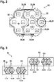
- FIG 2 shows an exemplary side view of a cell stack S1 of a battery 10 according to the invention.
- the side view represents one of the contacting sides of the cell stack S1, which has ten battery cells 20.
- Respective cell connectors 30 are shown, which connect respective contacting areas 25 of the battery cells 20 to one another in series and/or in parallel.
- the respective contact lugs 35 provided by the cell connectors 30 are provided in the first contacting section 50 and in the second contacting section 60 of the battery 10 so that they are accessible from the outside, so that the respective individual potentials of the battery 10 can be accessed on an outside of the cell stack S1.
- FIG 3 shows a schematic view of cell connectors 20 for a battery 10 according to the invention in a second embodiment.
- the battery 10 includes two cell stacks S1, S2, each of which includes ten battery cells 20.
- the respective battery cells 20 within the two cell stacks S1, S2 are electrically contacted by the cell connectors 30 described above, which are identified here schematically by a border around the battery cells 20 to be connected.
- FIG 4 shows a plan view of a first contacting section 50 of a battery 10 according to the invention in a third embodiment.
- a first stack connector 40 is shown in the first contacting section 50, which electrically connects the individual cell connectors 30 (not shown) of the cell stacks S1, S2, S3, S4 of the battery 10 to one another in such a way that a total voltage of the battery 10 is provided at a power connection 70.
- the first stack connector 40 is in the form of a stamped grid made of copper, which is integrated in a plastic holder.
- the first stack connector 40 is electrically connected to a part of the contact lugs 35 of the respective cell stacks S1, S2, S3, S4 by means of welded connections.
- Additional required electrical connections between the cell stacks S1 and S2 or between the cell stacks S3 and S4 are produced by direct contacting of contact lugs 35 by bending the respective contact lugs 35 of adjacent cell stacks S1, S2, S3, S4 in the direction of the arrow onto one another and then be welded together. Also shown are the voltages of the battery 10 that are available in this arrangement of battery cells 20 in the first contacting section 50.
- figure 5 shows a top view of a second contacting section 60 of the battery 10 according to the invention in the third embodiment.
- the second contacting section 60 is here on the opposite side of the battery 60, which is figure 4 is described.
- the respective contact lugs 35 of the cell connectors 30, which are provided in the second contacting section 60 of the battery 10, are shown.
- a second stack connector 45 which is embodied here as a flexible printed circuit board, all the individual potentials of the battery 10 that are provided are brought together at a signal connection 80 of the battery, so that the individual potentials of the battery 10 can be monitored.
- some of the contact lugs 35 are contacted directly by bending and welding (each in the direction of the arrow).
Landscapes
- Chemical & Material Sciences (AREA)
- Chemical Kinetics & Catalysis (AREA)
- Electrochemistry (AREA)
- General Chemical & Material Sciences (AREA)
- Connection Of Batteries Or Terminals (AREA)
- Primary Cells (AREA)
- Battery Mounting, Suspending (AREA)
Applications Claiming Priority (1)
| Application Number | Priority Date | Filing Date | Title |
|---|---|---|---|
| DE102020213480.4A DE102020213480A1 (de) | 2020-10-27 | 2020-10-27 | Batterie |
Publications (2)
| Publication Number | Publication Date |
|---|---|
| EP3993151A2 true EP3993151A2 (fr) | 2022-05-04 |
| EP3993151A3 EP3993151A3 (fr) | 2022-07-27 |
Family
ID=78085523
Family Applications (1)
| Application Number | Title | Priority Date | Filing Date |
|---|---|---|---|
| EP21201188.6A Pending EP3993151A3 (fr) | 2020-10-27 | 2021-10-06 | Batterie |
Country Status (4)
| Country | Link |
|---|---|
| US (1) | US20220131235A1 (fr) |
| EP (1) | EP3993151A3 (fr) |
| CN (1) | CN114497901A (fr) |
| DE (1) | DE102020213480A1 (fr) |
Family Cites Families (7)
| Publication number | Priority date | Publication date | Assignee | Title |
|---|---|---|---|---|
| DE102006061270B4 (de) * | 2006-12-22 | 2021-10-14 | Robert Bosch Gmbh | Batteriepack und Batteriemodul |
| DE102009050314A1 (de) | 2009-10-16 | 2011-04-21 | Elringklinger Ag | Verbinder zum elektrisch leitenden Verbinden von elektrischen Anschlüssen zweier Module |
| CN104078630B (zh) * | 2009-12-24 | 2017-02-08 | 三洋电机株式会社 | 电池组 |
| JP6731368B2 (ja) * | 2017-03-17 | 2020-07-29 | 株式会社シマノ | 自転車用バッテリユニット |
| DE102018006691A1 (de) | 2017-08-29 | 2019-02-28 | Marquardt Verwaltungs-Gmbh | Batteriesystem |
| GB2577261B (en) * | 2018-09-18 | 2022-05-25 | Mclaren Automotive Ltd | Battery |
| KR102301196B1 (ko) * | 2018-10-04 | 2021-09-09 | 주식회사 엘지에너지솔루션 | 접속 플레이트를 구비한 배터리 팩 |
-
2020
- 2020-10-27 DE DE102020213480.4A patent/DE102020213480A1/de active Pending
-
2021
- 2021-10-06 EP EP21201188.6A patent/EP3993151A3/fr active Pending
- 2021-10-25 US US17/452,184 patent/US20220131235A1/en active Pending
- 2021-10-26 CN CN202111245675.9A patent/CN114497901A/zh active Pending
Also Published As
| Publication number | Publication date |
|---|---|
| CN114497901A (zh) | 2022-05-13 |
| EP3993151A3 (fr) | 2022-07-27 |
| US20220131235A1 (en) | 2022-04-28 |
| DE102020213480A1 (de) | 2022-04-28 |
Similar Documents
| Publication | Publication Date | Title |
|---|---|---|
| DE112011101265B4 (de) | Sicherungseinheit | |
| DE112014006004B4 (de) | Verfahren zur Herstellung eines Batterieverdrahtungsmoduls | |
| DE112014006058B4 (de) | Batterieverdrahtungsmodul | |
| EP2064763A1 (fr) | Batterie haute tension présentant une unité de connexion, et unité de connexion correspondante | |
| DE112014006079B4 (de) | Verfahren zum Herstellen eines Batterieverdrahtungsmoduls | |
| DE102015225233A1 (de) | Batterieleitungsmodul und Batterieleitungsmodulherstellungsverfahren | |
| DE112011101401T5 (de) | Batterieverbindungsplatte | |
| DE102018212913A1 (de) | Leitermodul | |
| EP2692001A1 (fr) | Batterie pour véhicule automobile | |
| EP3433891B1 (fr) | Batterie et procédé de production d'une batterie | |
| DE102015225249A1 (de) | Herstellungsverfahren eines Batterieverkabelungsmoduls | |
| DE102010043885A1 (de) | Akkupack mit einer Vielzahl von Zellen und Verfahren zur Herstellung eines Akkupacks | |
| DE102012210999B4 (de) | Sicherungsblock und elektrischer Anschlusskasten, der diesen aufweist | |
| DE60315954T2 (de) | Laminierte kontakte in sockel | |
| DE102015225406A1 (de) | Zellenverbinder | |
| DE102018208896A1 (de) | Batteriemodul | |
| DE102006029731A1 (de) | Batterieanschluss | |
| DE102018205377A1 (de) | Leiterverbindungsstruktur eines laminierten Verdrahtungskörpers | |
| EP2791996B1 (fr) | Batterie de véhicule automobile | |
| EP3993151A2 (fr) | Batterie | |
| DE102013021240A1 (de) | Zellverbinderplatine und Batteriezellenblock mit einer Zellverbinderplatine | |
| EP2956976B1 (fr) | Élément de connexion d'éléments servant à relier de manière électriquement conductrice une pluralité de bornes d'éléments de batterie, procédé de fabrication d'un tel élément de connexion d'éléments et bloc batterie comprenant au moins un tel élément de connexion d'éléments | |
| DE102015225405A1 (de) | Energiebereitstellungszelle | |
| DE102007061816A1 (de) | Potentialverteiler und Verfahren zur Herstellung eines Potentialverteilers | |
| DE112015000905T5 (de) | Stromquellenvorrichtung |
Legal Events
| Date | Code | Title | Description |
|---|---|---|---|
| PUAI | Public reference made under article 153(3) epc to a published international application that has entered the european phase |
Free format text: ORIGINAL CODE: 0009012 |
|
| STAA | Information on the status of an ep patent application or granted ep patent |
Free format text: STATUS: THE APPLICATION HAS BEEN PUBLISHED |
|
| AK | Designated contracting states |
Kind code of ref document: A2 Designated state(s): AL AT BE BG CH CY CZ DE DK EE ES FI FR GB GR HR HU IE IS IT LI LT LU LV MC MK MT NL NO PL PT RO RS SE SI SK SM TR |
|
| PUAL | Search report despatched |
Free format text: ORIGINAL CODE: 0009013 |
|
| AK | Designated contracting states |
Kind code of ref document: A3 Designated state(s): AL AT BE BG CH CY CZ DE DK EE ES FI FR GB GR HR HU IE IS IT LI LT LU LV MC MK MT NL NO PL PT RO RS SE SI SK SM TR |
|
| RIC1 | Information provided on ipc code assigned before grant |
Ipc: H01M 50/516 20210101ALI20220620BHEP Ipc: H01M 50/509 20210101ALI20220620BHEP Ipc: H01M 50/507 20210101ALI20220620BHEP Ipc: H01M 50/503 20210101AFI20220620BHEP |
|
| STAA | Information on the status of an ep patent application or granted ep patent |
Free format text: STATUS: REQUEST FOR EXAMINATION WAS MADE |
|
| 17P | Request for examination filed |
Effective date: 20230127 |
|
| RBV | Designated contracting states (corrected) |
Designated state(s): AL AT BE BG CH CY CZ DE DK EE ES FI FR GB GR HR HU IE IS IT LI LT LU LV MC MK MT NL NO PL PT RO RS SE SI SK SM TR |