EP3992350A1 - Griffbaugruppe für eine waschmaschine - Google Patents
Griffbaugruppe für eine waschmaschine Download PDFInfo
- Publication number
- EP3992350A1 EP3992350A1 EP21202318.8A EP21202318A EP3992350A1 EP 3992350 A1 EP3992350 A1 EP 3992350A1 EP 21202318 A EP21202318 A EP 21202318A EP 3992350 A1 EP3992350 A1 EP 3992350A1
- Authority
- EP
- European Patent Office
- Prior art keywords
- connector
- handle assembly
- handle
- shell
- recessed grip
- Prior art date
- Legal status (The legal status is an assumption and is not a legal conclusion. Google has not performed a legal analysis and makes no representation as to the accuracy of the status listed.)
- Granted
Links
Images



Classifications
-
- D—TEXTILES; PAPER
- D06—TREATMENT OF TEXTILES OR THE LIKE; LAUNDERING; FLEXIBLE MATERIALS NOT OTHERWISE PROVIDED FOR
- D06F—LAUNDERING, DRYING, IRONING, PRESSING OR FOLDING TEXTILE ARTICLES
- D06F39/00—Details of washing machines not specific to a single type of machines covered by groups D06F9/00 - D06F27/00
- D06F39/02—Devices for adding soap or other washing agents
-
- D—TEXTILES; PAPER
- D06—TREATMENT OF TEXTILES OR THE LIKE; LAUNDERING; FLEXIBLE MATERIALS NOT OTHERWISE PROVIDED FOR
- D06F—LAUNDERING, DRYING, IRONING, PRESSING OR FOLDING TEXTILE ARTICLES
- D06F39/00—Details of washing machines not specific to a single type of machines covered by groups D06F9/00 - D06F27/00
- D06F39/12—Casings; Tubs
Definitions
- the invention relates to a handle assembly for a washing machine of the type mentioned in the preamble of patent claim 1.
- Such handle assemblies for washing machines are already known in a large number of embodiments and comprise, for example, a handle panel and a connection part which is connected in a force-transmitting manner to the handle panel in an assembled state of the handle assembly, with at least one first connector for force-transmitting connection of the handle assembly to a control panel of the washing machine being attached to the one-piece connection part and at least one second connector for force-transmitting connection of the handle assembly to a tank of the washing machine are formed.
- the invention therefore addresses the problem of specifying an improved handle assembly for a washing machine.
- a handle assembly for a washing machine having the features of patent claim 1, which is characterized in that the one-piece connecting part has a base section on which the first connector and the second connector are each arranged resiliently in such a way that the first connector and the second connector is positionable relative to the handle panel within predetermined limits independently of the other connector.
- the tank of the washing machine is, for example, a water tank, a condensate tank and/or a dispenser for water and detergent.
- the washing machine can be, for example, a washing machine for textiles, for crockery or for hospital accessories.
- the washing machine can be designed as a household appliance or as a commercial appliance, ie a washing machine for professional use.
- the advantage that can be achieved with the invention consists in particular in that a handle assembly for a washing machine is improved. Due to the design of the handle assembly for a washing machine according to the invention, it is possible on the one hand to keep the number of components of a handle assembly for a washing machine as low as possible and on the other hand to individually position the at least one first connector for the force-transmitting connection of the handle assembly to a control panel of the washing machine in pre-established limits independent of an individual To be able to position the at least one second connector for force-transmitting connection of the handle assembly with a container of the washing machine.
- the at least one first and the at least one second connector can thus be positioned independently of one another relative to the handle cover to the extent necessary for producing the washing machine equipped with the handle assembly according to the invention. Furthermore, the reduction in the number of components in the handle assembly according to the invention for a washing machine also reduces warehousing and logistics as well as the assembly work and thus the production work involved in the manufacture of the handle assembly according to the invention and thus in the manufacture of the washing machine equipped with it.
- the handle assembly according to the invention for a washing machine can be freely selected in terms of type, function, material, dimensioning and arrangement within wide, suitable limits.
- first connector and the second connector are each arranged by means of a resilient tongue of the connecting part on the base section of the connecting part.
- the resilient arrangement of the first and the second connector on the base section of the one-piece connecting part is implemented in a structurally particularly simple and robust manner.
- a particularly advantageous development of the aforementioned embodiment of the handle assembly according to the invention for a washing machine provides that the resilient tongue is designed in a meandering shape. As a result, the mechanical properties of the respective resilient tongue are significantly improved.
- a further advantageous development of the handle assembly according to the invention for a washing machine provides that the first and/or the second connector and the handle panel have mutually corresponding connector interlocking means, by means of which the respective connector can be held in the assembled state of the handle assembly in a form-fitting manner on the handle panel.
- the non-positive connection between the handle panel on the one hand and the connecting part on the other side is made possible in a simple and robust manner in the assembled state of the handle assembly according to the invention.
- this non-positive connection between the handle panel and the first connector and between the handle panel and the second connector of the connecting part allows the first and second connector of the connecting part to be positioned very precisely relative to the handle panel.
- the handle assembly according to the invention and thus in particular the handle panel of the handle assembly can be positioned very precisely on the control panel of the washing machine as well as on the container of the washing machine, so that on the one hand a good gap image between the control panel and the handle panel and on the other hand a good mobility of the container is made possible by means of the handle assembly.
- the at least one connector form-fitting means of the handle panel is designed as a projection and the at least one connector form-fitting means of the first and/or the second connector is designed as an opening designed to correspond to the projection that the projection can be deformed during the transfer of the handle assembly into its assembled state in such a way that the mutually corresponding connector form-fitting means are non-detachably connected to one another in the assembled state of the handle assembly.
- the mutually corresponding positive-locking connector means of the handle panel on the one hand and of the connecting part on the other side are implemented in a structurally particularly simple manner.
- the at least one projection of the handle panel can be designed in such a way that the at least one first connector and/or the at least one second connector of the connecting part can be fixed in at least two spatial directions by means of the projection.
- the handle assembly according to the invention for a washing machine provides that the first connector and/or the second connector are/is designed in such a way that the handle assembly can be positively connected to the control panel and/or to the container in its assembled state, preferably that the first connector and the control panel and/or the second connector and the container have latching means which correspond to one another for this purpose.
- the handle assembly can be positively connected to the control panel and/or to the container in its assembled state, preferably that the first connector and the control panel and/or the second connector and the container have latching means which correspond to one another for this purpose.
- a force-transmitting connection between the handle assembly with the handle panel on the one hand and the control panel and/or the container on the other side is made possible in a structurally simple and robust manner.
- the manufacture of the washing machine equipped with the handle assembly according to the invention is also correspondingly simplified. This applies in particular to the preferred embodiment of the present development.
- a particularly advantageous development of the handle assembly according to the invention for a washing machine provides that the connecting part is designed at the same time as a recessed grip part of a recessed grip of the handle assembly. This increases the functionality of the connecting part, so that the connecting part is not only used for the force-transmitting connection of the handle assembly with the control panel on the one hand and the container on the other side, but that the connecting part also has the function of a recessed grip part to form a recessed grip of the handle assembly.
- the recessed grip part is designed as a first recessed grip half-shell and can be connected to a second recessed grip half-shell of the grip assembly when the grip assembly is transferred to its assembled state such that the first and second recessed grip half-shells are in the assembled state the handle assembly form a single recessed grip shell, preferably that the grip panel has a recessed grip shell corresponding to the recessed grip shell.
- the formation of a complete recessed grip on the handle assembly according to the invention is made possible with simple means. This applies in particular to the preferred embodiment of the present development.
- first recessed grip half-shell, the second recessed grip half-shell and the handle cover have mutually corresponding shell form-fitting means, with the shell form-fitting means of the first and the second recessed grip half-shell corresponding to the at least one shell form-fitting means of the handle cover in this way that the first recessed grip half-shell and the second recessed grip half-shell are positively fixed to the handle cover in the assembled state of the handle assembly.
- This enables a force-transmitting connection between the first recessed grip half-shell, the second recessed grip half-shell and the grip panel to form the recessed grip of the grip assembly in a way that is particularly simple in terms of design and production technology.
- a further advantageous development of the handle assembly according to the invention for a washing machine provides that the handle cover and the connecting part are made of different materials, preferably that the handle cover is made of an ASA plastic or an ABS plastic and the connecting part is made of a POM plastic .
- the handle panel of the handle assembly on the one hand and the connecting part of the handle assembly on the other side can be designed independently of one another with regard to the choice of material.
- the most suitable material for the respective function can be selected for the handle cover and for the connecting part.
- ASA plastic i.e. acrylonitrile-styrene-acrylate copolymer
- ABS plastic i.e.
- ASA plastic and ABS plastic have good tolerance and shrinkage characteristics compared to POM plastic.
- ABS plastic is less expensive compared to ASA plastic.
- POM plastic i.e. polyoxymethylene
- POM plastic has good spring and sliding properties.
- the washing machine is designed as a household appliance for washing textiles and in the Figures 1 to 4b not shown in detail.
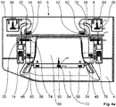
- the washing machine has a handle assembly 2, comprising a handle panel 4 and in one in the Figure 4a and 4b
- the illustrated assembly state of the handle assembly 2 is connected to the handle panel 4 in a force-transmitting connection part 6, with two first connectors 8, 10 on the one-piece connection part 6 for the force-transmitting connection of the handle assembly 2 to a control panel (not shown) of the washing machine and two second connectors 12, 14 for the force-transmitting connection of the Handle assembly 2 are formed with a trained as a dispenser for water and detergent, also not shown container of the washing machine.
- the handle cover 4 and the connecting part 6 are made of different materials, the handle cover 4 being made of ABS plastic on the one hand and the connecting part 6 being made of POM plastic on the other hand.
- the one-piece connector 6 has a base portion 16 on which the first connectors 8, 10 and the second connectors 12, 14 are respectively resiliently mounted such that the first connectors 8, 10 and the second connectors 12, 14 are independently within predetermined limits from the respective other connectors 8, 10, 12, 14 relative to the Handle panel 4 can be positioned.
- the first connectors 8, 10 and the second connectors 12, 14 are each arranged on the base section 16 of the connecting part 6 by means of a resilient tongue 18, 20, 22, 24 of the connecting part 6, the respective resilient tongue 18, 20, 22, 24 is designed meandering.
- a resilient tongue 18, 20, 22, 24 of the connecting part 6 the respective resilient tongue 18, 20, 22, 24 is designed meandering.
- the first and the second connectors 8, 10, 12 , 14 and the handle panel 4 have corresponding connector form-fitting means 26, 28, 30, 32, 34, 36, 38, 40, by means of which the respective connector 8, 10, 12, 14 can be held in the assembled state of the handle assembly 2 in a form-fitting manner on the handle panel 4 is.
- the base section 16 of the connecting part 6 and the handle panel 4 have base positive-locking means 42, 44, 46, 48, 50, 52, 54, 56 which correspond to one another.
- the connector form-fitting means 34, 36, 38, 40 and the base form-fitting means 50, 52, 54, 56 of the handle panel 4 are each in the form of a projection and the connector form-fitting means 26, 28, 30, 32 of the first and second connectors 8, 10, 12, 14 and the base form-fitting means 42, 44, 46, 48 of the base section 16 are each designed as an opening 26, 28, 30, 32, 42, 44 corresponding to the respective projection 34, 36, 38, 40, 50, 52, 54, 56 , 46, 48, namely in such a way that the respective projection 34, 36, 38, 40, 50, 52, 54, 56 can be deformed when the handle assembly 2 is transferred into its assembled state in such a way that the mutually corresponding connector form-fitting means 26, 28, 30, 32 and 34, 36, 38, 40 and the mutually corresponding basic form-fitting means 42, 44, 46, 48 and 50, 52, 54, 56 are permanently connected to one another in the assembled state of the handle assembly 2.
- first connectors 8, 10 and the second connectors 12, 14 are designed in such a way that the handle assembly 2 can be positively connected to the control panel and to the container in the assembled state, namely in such a way that the first connectors 8, 10 and the not shown
- the control panel and the second connectors 12, 14 and the container, also not shown, have latching means 58, 60, 62, 64 that correspond to one another.
- the connecting part 6 of the handle assembly 2 is designed at the same time as a recessed grip part of a recessed grip 66 of the handle assembly 2, the recessed grip part, i.e. the connecting part 6, being designed as a first recessed grip half-shell and when the handle assembly 2 is transferred to its assembled state a second recessed grip half-shell 68 of the handle assembly 2, so that the first and the second recessed grip half-shells 6, 68 form a single recessed grip shell 70 in the assembled state of the grip assembly 2, with the grip cover 4 having a recessed grip half-shell 72 that corresponds to the recessed grip shell 70. See in particular the Figure 4b . Together, the recessed grip half-shells 6, 68 and 72 form the recessed grip 66 in the assembled state of the grip assembly 2.
- the connector form-fitting means 30, 32 and the base form-fitting means 46, 48 are simultaneously designed as shell form-fitting means of the first recessed grip half-shell, namely the connecting part 6.
- the connector form-fitting means 38, 40 and the base form-fitting means 54, 56 are designed at the same time as shell form-fitting means of the handle cover 4.
- the separate second recessed grip half-shell 68 of the handle assembly 2 has shell form-locking means 74, 76, 78, 80 that correspond to the aforementioned connector form-locking means 30, 32, 38, 40 and base form-locking means 46, 48, 54, 56 and are designed as openings.
- the recessed grip half-shell 72 of the handle cover 4 and the second recessed grip half-shell 68 have shell form-fitting means 82, 84, 86, 88, 90, 92 that correspond to one another, with the shell form-fitting means 82, 84, 86 of the second recessed grip half-shell 68 acting as openings and the shell form-fitting means 88, 90 , 92 of the recessed grip half-shell 72 are designed as projections.
- the connecting part 6 is first connected to the handle panel 4 of the handle assembly 2 in a force-transmitting manner.
- the connecting part 6, as can be seen from the synopsis of 1 and 3 removable, attached to the handle panel 4.
- the connector form-fitting means 26, 28 of the first connector 8, 10 designed as openings are fitted to the connector form-fitting means 34, 36 of the handle cover 4 designed as projections, the connector form-fitting means 30, 32 of the second connectors 12, 14 designed as openings to the connector form-fitting means designed as projections 38, 40 of the handle cover 4 and the basic form-fitting means 42, 44, 46, 48, designed as openings, of the base section 16 of the connecting part 6 are pushed onto the basic form-fitting means 50, 52, 54, 56, designed as projections, of the handle cover 4.
- the second recessed grip half-shell 68 is then attached to the aforementioned arrangement of the grip cover 4 and the connecting part 6 . See the 3 and 4a as well as 4b in synopsis.
- the second recessed grip half-shell 68 is pushed onto the shell form-fitting means 38, 40, 54, 56, 88, 90, 92 of the handle cover, designed as projections, by means of the shell positive-locking means 74, 76, 78, 80, 82, 84, 86 of the second recessed grip shell 68 designed as openings 4 attached.
- the connecting part 6 is arranged between the handle panel 4 and between the second recessed grip half-shell 68 .
- the aforementioned projections 34, 36, 38, 40, 50, 52, 54, 56, 88, 90, 92 of the handle cover 4 in the present exemplary embodiment is heat-staked in a manner known to those skilled in the art.
- the handle assembly 2 is now in its assembled state and can subsequently be handled as a unit.
- the container has latching means (not shown) designed to correspond to the latching means 62, 64 of the second connectors 12, 14, so that the handle assembly 2, namely the second connectors 12, 14, is connected to the container by means of a latching connection.
- latching means designed to correspond to the latching means 62, 64 of the second connectors 12, 14, so that the handle assembly 2, namely the second connectors 12, 14, is connected to the container by means of a latching connection.
- the container can then be pushed into a removable drawer formed in the control panel of the washing machine in a manner known to those skilled in the art by means of the handle assembly 2 .
- a user grasps the handle assembly 2 by means of the recessed grip 66 formed on the handle assembly 2 and pushes the container into the aforementioned drawer.
- the handle panel 4 of the handle assembly 2 is essentially flush with the control panel of the washing machine.
- the handle assembly 2 Due to the handle assembly 2, it is thus possible to keep the number of components of the handle assembly 2 for a washing machine small.
- individual positioning of the first connector 8, 10 for the force-transmitting connection of the handle assembly 2 to the control panel of the washing machine relative to the handle panel 4 within predetermined limits is independent of the individual positioning of the second connector 12, 14 for the force-transmitting connection the handle assembly 2 with the tank of the washing machine possible.
- the first and second connectors 8, 10, 12, 14 are thus independent of one another to the extent necessary for the manufacture of the washing machine equipped with the handle assembly 2 according to the invention relative to the handle cover 4 positionable.
- the reduction in the number of components in the handle assembly 2 also reduces warehousing and logistics as well as the assembly work and thus the production work involved in the manufacture of the handle assembly 2 and thus in the manufacture of the washing machine equipped with it.
- ABS plastic ie acrylonitrile-butadiene-styrene copolymer
- POM plastic ie polyoxymethylene
- the Handle assembly 2 on one side relative to the washing machine control panel a good split image and thus high quality aesthetics of the washing machine.
- the container can be easily moved when it is pushed into the drawer formed on the control panel and when it is pulled out of the drawer.
- the tank of the washing machine can also be a water tank, a condensate tank and/or a dispenser for water and detergent.
- the washing machine can be, for example, a washing machine for textiles, for crockery or for hospital accessories.
- the washing machine can also be designed as a combination device, for example a washer-dryer.
- the washing machine can be designed as a household appliance or as a commercial appliance, ie a washing machine for professional use.
- the connecting part can only be designed to be suitable for the function as a connecting part. Accordingly, embodiments of the invention are conceivable in which the connecting part is not simultaneously designed as a recessed grip part.
- Embodiments are also possible in which, even with a plurality of first connectors and/or second connectors, the individual first connectors among one another and/or the individual second connectors among one another relative to the handle cover cannot be positioned individually.
Landscapes
- Engineering & Computer Science (AREA)
- Textile Engineering (AREA)
- Detail Structures Of Washing Machines And Dryers (AREA)
- Details Of Rigid Or Semi-Rigid Containers (AREA)
- Main Body Construction Of Washing Machines And Laundry Dryers (AREA)
Abstract
Description
- Die Erfindung betrifft eine Griffbaugruppe für eine Waschmaschine der im Oberbegriff des Patentanspruchs 1 genannten Art.
- Derartige Griffbaugruppen für Waschmaschinen sind in einer Vielzahl von Ausführungsformen bereits vorbekannt und umfassen beispielsweise eine Griffblende und ein in einem Montagezustand der Griffbaugruppe mit der Griffblende kraftübertragend verbundenes Verbindungsteil, wobei an dem einstückigen Verbindungsteil mindestens ein erster Verbinder zur kraftübertragenden Verbindung der Griffbaugruppe mit einer Bedienblende der Waschmaschine und mindestens ein zweiter Verbinder zur kraftübertragenden Verbindung der Griffbaugruppe mit einem Behälter der Waschmaschine ausgebildet sind.
- Der Erfindung stellt sich somit das Problem, eine verbesserte Griffbaugruppe für eine Waschmaschine anzugeben.
- Erfindungsgemäß wird dieses Problem durch eine Griffbaugruppe für eine Waschmaschine mit den Merkmalen des Patentanspruchs 1 gelöst, die dadurch gekennzeichnet ist, dass das einstückige Verbindungsteil einen Basisabschnitt aufweist, an dem der erste Verbinder und der zweite Verbinder jeweils derart federnd angeordnet sind, dass der erste Verbinder und der zweite Verbinder in vorher festgelegten Grenzen unabhängig von dem jeweils anderen Verbinder relativ zu der Griffblende positionierbar sind. Bei dem Behälter der Waschmaschine handelt es sich beispielsweise um einen Wasserbehälter, einen Kondensatbehälter und/oder um einen Einspülkasten für Wasser und Waschmittel. Bei der Waschmaschine kann es sich beispielsweise um eine Waschmaschine für Textilien, für Geschirr oder für Krankenhauszubehör handeln. Ferner kann die Waschmaschine als ein Haushaltsgerät oder ein gewerbliches Gerät, also eine Waschmaschine für den professionellen Einsatz, ausgebildet sein. Vorteilhafte Ausgestaltungen und Weiterbildungen der Erfindung ergeben sich aus den nachfolgenden Unteransprüchen.
- Der mit der Erfindung erreichbare Vorteil besteht insbesondere darin, dass eine Griffbaugruppe für eine Waschmaschine verbessert ist. Aufgrund der erfindungsgemäßen Ausbildung der Griffbaugruppe für eine Waschmaschine ist es möglich, zum einen die Anzahl der Bauteile einer Griffbaugruppe für eine Waschmaschine möglichst gering zu halten und zum anderen eine individuelle Positionierung des mindestens einen ersten Verbinders zur kraftübertragenden Verbindung der Griffbaugruppe mit einer Bedienblende der Waschmaschine in vorher festgelegten Grenzen unabhängig von einer individuellen Positionierung des mindestens einen zweiten Verbinders zur kraftübertragenden Verbindung der Griffbaugruppe mit einem Behälter der Waschmaschine vornehmen zu können. Der mindestens eine erste und der mindestens eine zweite Verbinder sind somit im für die Herstellung der mit der erfindungsgemäßen Griffbaugruppe ausgestatteten Waschmaschine notwendigen Umfang voneinander unabhängig relativ zu der Griffblende positionierbar. Ferner sind durch die Reduzierung der Bauteile bei der erfindungsgemäßen Griffbaugruppe für eine Waschmaschine auch die Lagerhaltung und die Logistik sowie der Montageaufwand und damit der Fertigungsaufwand bei der Herstellung der erfindungsgemäßen Griffbaugruppe und damit bei der Herstellung der damit ausgestatteten Waschmaschine verringert.
- Grundsätzlich ist die erfindungsgemäße Griffbaugruppe für eine Waschmaschine nach Art, Funktionsweise, Material, Dimensionierung und Anordnung in weiten geeigneten Grenzen frei wählbar.
- Eine vorteilhafte Weiterbildung der erfindungsgemäßen Griffbaugruppe für eine Waschmaschine sieht vor, dass der erste Verbinder und der zweite Verbinder jeweils mittels einer federnden Zunge des Verbindungsteils an dem Basisabschnitt des Verbindungsteils angeordnet sind. Auf diese Weise ist die federnde Anordnung des ersten und des zweiten Verbinders an dem Basisabschnitt des einstückigen Verbindungsteils auf konstruktiv besonders einfache und robuste Art realisiert.
- Eine besonders vorteilhafte Weiterbildung der vorgenannten Ausführungsform der erfindungsgemäßen Griffbaugruppe für eine Waschmaschine sieht vor, dass die federnde Zunge mäanderförmig ausgebildet ist. Hierdurch sind die mechanischen Eigenschaften der jeweiligen federnden Zunge wesentlich verbessert.
- Eine weitere vorteilhafte Weiterbildung der erfindungsgemäßen Griffbaugruppe für eine Waschmaschine sieht vor, dass der erste und/oder der zweite Verbinder und die Griffblende zueinander korrespondierende Verbinderformschlussmittel aufweisen mittels derer der jeweilige Verbinder in dem Montagezustand der Griffbaugruppe formschlüssig an der Griffblende halterbar ist. Auf diese Weise ist zum einen die kraftschlüssige Verbindung zwischen der Griffblende auf der einen Seite und dem Verbindungsteil auf der anderen Seite in dem Montagezustand der erfindungsgemäßen Griffbaugruppe auf einfache und robuste Art ermöglicht. Zum anderen ist durch diese kraftschlüssige Verbindung zwischen der Griffblende und dem ersten Verbinder sowie zwischen der Griffblende und dem zweiten Verbinder des Verbindungsteils eine sehr genaue Positionierung des ersten und des zweiten Verbinders des Verbindungsteils jeweils relativ zu der Griffblende realisierbar. Entsprechend ist die erfindungsgemäße Griffbaugruppe und damit insbesondere die Griffblende der Griffbaugruppe sehr genau zu der Bedienblende der Waschmaschine wie auch zu dem Behälter der Waschmaschine positionierbar, so dass zum einen ein gutes Spaltbild zwischen der Bedienblende und der Griffblende und zum anderen eine gute Beweglichkeit des Behälters mittels der Griffbaugruppe ermöglicht ist.
- Eine vorteilhafte Weiterbildung der vorgenannten Ausführungsform der erfindungsgemäßen Griffbaugruppe für eine Waschmaschine sieht vor, dass das mindestens eine Verbinderformschlussmittel der Griffblende als ein Vorsprung und das mindestens eine Verbinderformschlussmittel des ersten und/oder des zweiten Verbinders als eine zu dem Vorsprung korrespondierend ausgebildete Öffnung ausgebildet sind, bevorzugt, dass der Vorsprung bei der Überführung der Griffbaugruppe in deren Montagezustand derart verformbar ist, dass die zueinander korrespondierenden Verbinderformschlussmittel in dem Montagezustand der Griffbaugruppe miteinander unlösbar verbunden sind. Hierdurch sind die zueinander korrespondierenden Verbinderformschlussmittel der Griffblende auf der einen Seite und des Verbindungsteils auf der anderen Seite auf konstruktiv besonders einfache Art und Weise verwirklicht. Der mindestens eine Vorsprung der Griffblende kann dabei derart ausgebildet sein, dass der mindestens eine erste Verbinder und/oder der mindestens eine zweite Verbinder des Verbindungsteils mittels des Vorsprungs in mindestens zwei Raumrichtungen fixierbar ist.
- Eine andere vorteilhafte Weiterbildung der erfindungsgemäßen Griffbaugruppe für eine Waschmaschine sieht vor, dass der erste Verbinder und/oder der zweite Verbinder derart ausgebildet sind/ist, dass die Griffbaugruppe in deren Montagezustand formschlüssig mit der Bedienblende und/oder mit dem Behälter verbindbar ist, bevorzugt, dass der erste Verbinder und die Bedienblende und/oder der zweite Verbinder und der Behälter hierfür zueinander korrespondierende Rastmittel aufweisen. Auf diese Weise ist eine kraftübertragende Verbindung zwischen der Griffbaugruppe mit der Griffblende auf der einen Seite und der Bedienblende und/oder dem Behälter auf der anderen Seite auf konstruktiv einfache und robuste Art ermöglicht. Entsprechend vereinfacht sich auch die Herstellung der mit der erfindungsgemäßen Griffbaugruppe ausgestatteten Waschmaschine. Dies gilt insbesondere für die bevorzugte Ausführungsform der vorliegenden Weiterbildung.
- Eine besonders vorteilhafte Weiterbildung der erfindungsgemäßen Griffbaugruppe für eine Waschmaschine sieht vor, dass das Verbindungsteil gleichzeitig als ein Griffmuldenteil einer Griffmulde der Griffbaugruppe ausgebildet ist. Hierdurch ist die Funktionalität des Verbindungsteils gesteigert, so dass das Verbindungsteil nicht lediglich zur kraftübertragenden Verbindung der Griffbaugruppe mit der Bedienblende auf der einen Seite und dem Behälter auf der anderen Seite dient, sondern, dass das Verbindungsteil gleichzeitig die Funktion eines Griffmuldenteils zur Ausbildung einer Griffmulde an der Griffbaugruppe erfüllt.
- Eine vorteilhafte Weiterbildung der vorgenannten Ausführungsform der erfindungsgemäßen Griffbaugruppe sieht vor, dass das Griffmuldenteil als eine erste Griffmuldenhalbschale ausgebildet ist und bei der Überführung der Griffbaugruppe in deren Montagezustand derart mit einer zweiten Griffmuldenhalbschale der Griffbaugruppe verbindbar ist, dass die erste und die zweite Griffmuldenhalbschale in dem Montagezustand der Griffbaugruppe eine einzige Griffmuldenschale ausbilden, bevorzugt, dass die Griffblende eine zu der Griffmuldenschale korrespondierende Griffmuldenhalbschale aufweist. Auf diese Weise ist die Ausbildung einer vollständigen Griffmulde an der erfindungsgemäßen Griffbaugruppe mit einfachen Mitteln ermöglicht. Dies gilt insbesondere für die bevorzugte Ausführungsform der vorliegenden Weiterbildung.
- Eine vorteilhafte Weiterbildung der letztgenannten Ausführungsform der erfindungsgemäßen Griffbaugruppe für eine Waschmaschine sieht vor, dass die erste Griffmuldenhalbschale, die zweite Griffmuldenhalbschale und die Griffblende zueinander korrespondierende Schalenformschlussmittel aufweisen, wobei die Schalenformschlussmittel der ersten und der zweiten Griffmuldenhalbschale gemeinsam zu dem mindestens einen Schalenformschlussmittel der Griffblende derart korrespondieren, dass die erste Griffmuldenhalbschale und die zweite Griffmuldenhalbschale in dem Montagezustand der Griffbaugruppe formschlüssig an der Griffblende festgelegt sind. Hierdurch ist eine kraftübertragende Verbindung zwischen der ersten Griffmuldenhalbschale, der zweiten Griffmuldenhalbschale und der Griffblende zur Ausbildung der Griffmulde der Griffbaugruppe auf konstruktiv und fertigungstechnisch besonders einfache Art ermöglicht.
- Eine weitere vorteilhafte Weiterbildung der erfindungsgemäßen Griffbaugruppe für eine Waschmaschine sieht vor, dass die Griffblende und das Verbindungsteil materialverschieden ausgebildet sind, bevorzugt, dass die Griffblende einerseits aus einem ASA-Kunststoff oder einem ABS-Kunststoff und das Verbindungsteil andererseits aus einem POM-Kunststoff ausgebildet ist. Auf diese Weise sind die Griffblende der Griffbaugruppe auf der einen Seite und das Verbindungsteil der Griffbaugruppe auf der anderen Seite hinsichtlich der Materialwahl unabhängig voneinander gestaltbar. Entsprechend lässt sich für die Griffblende und für das Verbindungsteil das für die jeweilige Funktion am besten geeignete Material auswählen. Dies gilt insbesondere für die bevorzugte Ausführungsform der vorliegenden Weiterbildung. Beispielsweise ist ASA-Kunststoff, also Acrylnitril-Styrol-Acrylat-Copolymer, oder ABS-Kunststoff, also Acrylnitril-Butadien-Styrol-Copolymer, zur Herstellung der Griffblende gut geeignet. ASA-Kunststoff und ABS-Kunststoff besitzen im Vergleich zu POM-Kunststoff eine gute Toleranz- und Schwindungseigenschaft. Darüber hinaus ist ABS-Kunststoff im Vergleich zu ASA-Kunststoff kostengünstiger. Im Unterschied dazu eignet sich POM-Kunststoff, also Polyoxymethylen, sehr gut für das Verbindungsteil. POM-Kunststoff besitzt eine gute Feder- und Gleiteigenschaft.
- Ein Ausführungsbeispiel der Erfindung ist in den Zeichnungen rein schematisch dargestellt und wird nachfolgend näher beschrieben. Es zeigt
- Figur 1
- ein Ausführungsbeispiel der erfindungsgemäßen Griffbaugruppe für eine Waschmaschine in einer teilweisen Rückansicht, mit Blick auf die Griffblende in einer Einzeldarstellung,
- Figur 2a
- das Ausführungsbeispiel in einer teilweisen perspektivischen Ansicht, mit Blick auf das Verbindungsteil in einer Einzeldarstellung,
- Figur 2b
- das Verbindungsteil des Ausführungsbeispiels in einer, im Vergleich zu der
Fig. 2a , um 180° gedrehten, perspektivischen Einzeldarstellung, - Figur 3
- das Ausführungsbeispiel bei der Überführung in dessen Montagezustand in einer weiteren teilweisen Rückansicht, mit Blick auf die Griffblende und das Verbindungsteil,
- Figur 4a
- das Ausführungsbeispiel in dessen Montagezustand in einer Rückansicht und
- Figur 4b
- das Ausführungsbeispiel in dessen Montagezustand in einer perspektivischen Rückansicht.
- In den
Fig. 1 bis 4b ist ein Ausführungsbeispiel der erfindungsgemäßen Griffbaugruppe für eine Waschmaschine rein exemplarisch dargestellt. - Die Waschmaschine ist als ein Haushaltsgerät zum Waschen von Textilien ausgebildet und in den
Fig. 1 bis 4b nicht näher dargestellt. Die Waschmaschine weist eine Griffbaugruppe 2 auf, umfassend eine Griffblende 4 und ein in einem in denFig. 4a und4b dargestellten Montagezustand der Griffbaugruppe 2 mit der Griffblende 4 kraftübertragend verbundenes Verbindungsteil 6, wobei an dem einstückigen Verbindungsteil 6 zwei erste Verbinder 8, 10 zur kraftübertragenden Verbindung der Griffbaugruppe 2 mit einer nicht dargestellten Bedienblende der Waschmaschine und zwei zweite Verbinder 12, 14 zur kraftübertragenden Verbindung der Griffbaugruppe 2 mit einem als Einspülkasten für Wasser und Waschmittel ausgebildeten, ebenfalls nicht dargestellten Behälter der Waschmaschine ausgebildet sind. - Die Griffblende 4 und das Verbindungsteil 6 sind bei dem vorliegenden Ausführungsbeispiel materialverschieden ausgebildet, wobei die Griffblende 4 einerseits aus einem ABS-Kunststoff und das Verbindungsteil 6 andererseits aus einem POM-Kunststoff ausgebildet ist.
- Das einstückige Verbindungsteil 6 weist einen Basisabschnitt 16 auf, an dem die ersten Verbinder 8, 10 und die zweiten Verbinder 12, 14 jeweils derart federnd angeordnet sind, dass die ersten Verbinder 8, 10 und die zweiten Verbinder 12, 14 in vorher festgelegten Grenzen unabhängig von den jeweils anderen Verbindern 8, 10, 12, 14 relativ zu der Griffblende 4 positionierbar sind. Bei dem vorliegenden Ausführungsbeispiel bedeutet dies, dass der erste Verbinder 8 in den vorgenannten Grenzen unabhängig von dem ersten Verbinder 10 und den zweiten Verbindern 12, 14 relativ zu der Griffblende 4 positionierbar ist. Für die übrigen Verbinder 10, 12, 14 gilt Entsprechendes.
- Die ersten Verbinder 8, 10 und die zweiten Verbinder 12, 14 sind jeweils mittels einer federnden Zunge 18, 20, 22, 24 des Verbindungsteils 6 an dem Basisabschnitt 16 des Verbindungsteils 6 angeordnet, wobei die jeweilige federnde Zunge 18, 20, 22, 24 mäanderförmig ausgebildet ist. Siehe hierzu beispielsweise die
Fig. 2a . - Zwecks Überführung der Griffbaugruppe 2 in deren in den
Fig. 4a und4b gezeigten Montagezustand, also zwecks kraftübertragender Verbindung des Verbindungsteils 6 mit der Griffblende 4 auf der einen Seite und der individuellen Positionierung jedes der Verbinder 8, 10, 12, 14 relativ zu der Griffblende 4, weisen die ersten und die zweiten Verbinder 8, 10, 12, 14 und die Griffblende 4 zueinander korrespondierende Verbinderformschlussmittel 26, 28, 30, 32, 34, 36, 38, 40 auf, mittels derer der jeweilige Verbinder 8, 10, 12, 14 in dem Montagezustand der Griffbaugruppe 2 formschlüssig an der Griffblende 4 halterbar ist. Darüber hinaus weisen der Basisabschnitt 16 des Verbindungsteils 6 und die Griffblende 4 zueinander korrespondierende Basisformschlussmittel 42, 44, 46, 48, 50, 52, 54, 56 auf. - Die Verbinderformschlussmittel 34, 36, 38, 40 und die Basisformschlussmittel 50, 52, 54, 56 der Griffblende 4 sind jeweils als ein Vorsprung und die Verbinderformschlussmittel 26, 28, 30, 32 der ersten und der zweiten Verbinder 8, 10, 12, 14 und die Basisformschlussmittel 42, 44, 46, 48 des Basisabschnitts 16 sind jeweils als eine zu dem jeweiligen Vorsprung 34, 36, 38, 40, 50, 52, 54, 56 korrespondierend ausgebildete Öffnung 26, 28, 30, 32, 42, 44, 46, 48 ausgebildet, nämlich derart, dass der jeweilige Vorsprung 34, 36, 38, 40, 50, 52, 54, 56 bei der Überführung der Griffbaugruppe 2 in deren Montagezustand derart verformbar ist, dass die zueinander korrespondierenden Verbinderformschlussmittel 26, 28, 30, 32 und 34, 36, 38, 40 sowie die zueinander korrespondierenden Basisformschlussmittel 42, 44, 46, 48 und 50, 52, 54, 56 in dem Montagezustand der Griffbaugruppe 2 miteinander unlösbar verbunden sind. Hierzu sind die vorgenannten Vorsprünge 34, 36, 38, 40, 50, 52, 54, 56 beispielsweise auf dem Fachmann bekannte Weise heißverstemmbar.
- Ferner sind die ersten Verbinder 8, 10 und die zweiten Verbinder 12, 14 derart ausgebildet, dass die Griffbaugruppe 2 in deren Montagezustand formschlüssig mit der Bedienblende und mit dem Behälter verbindbar ist, nämlich derart, dass die ersten Verbinder 8, 10 und die nicht dargestellte Bedienblende und die zweiten Verbinder 12, 14 und der ebenfalls nicht dargestellte Behälter hierfür zueinander korrespondierende Rastmittel 58, 60, 62, 64 aufweisen.
- Bei dem vorliegenden Ausführungsbeispiel ist das Verbindungsteil 6 der Griffbaugruppe 2 gleichzeitig als eine Griffmuldenteil einer Griffmulde 66 der Griffbaugruppe 2 ausgebildet, wobei das Griffmuldenteil, also das Verbindungsteil 6, als eine erste Griffmuldenhalbschale ausgebildet ist und bei der Überführung der Griffbaugruppe 2 in deren Montagezustand derart mit einer zweiten Griffmuldenhalbschale 68 der Griffbaugruppe 2 verbindbar ist, dass die erste und die zweite Griffmuldenhalbschale 6, 68 in dem Montagezustand der Griffbaugruppe 2 eine einzige Griffmuldenschale 70 ausbilden, wobei die Griffblende 4 eine zu der Griffmuldenschale 70 korrespondierende Griffmuldenhalbschale 72 aufweist. Siehe hierzu insbesondere die
Fig. 4b . Gemeinsam bilden die Griffmuldenhalbschalen 6, 68 und 72 in dem Montagezustand der Griffbaugruppe 2 die Griffmulde 66 aus. - Zwecks kraftschlüssiger Verbindung des als erste Griffmuldenhalbschale ausgebildeten Verbindungsteils 6 mit der separaten zweiten Griffmuldenhalbschale 68 und der die Griffmuldenhalbschale 72 aufweisenden Griffblende 4 weisen die erste Griffmuldenhalbschale 6, die zweite Griffmuldenhalbschale 68 und die Griffblende 4, nämlich die an der Griffblende 4 ausgebildete Griffmuldenhalbschale 72, zueinander korrespondierende Schalenformschlussmittel auf, wobei die Schalenformschlussmittel der ersten und der zweiten Griffmuldenhalbschale 6, 68 gemeinsam zu den Schalenformschlussmitteln der Griffblende 4 derart korrespondieren, dass die erste Griffmuldenhalbschale 6 und die zweite Griffmuldenhalbschale 68 in dem Montagezustand der Griffbaugruppe 2 formschlüssig an der Griffblende 4 festgelegt sind.
- Bei dem vorliegenden Ausführungsbeispiel sind die Verbinderformschlussmittel 30, 32 und die Basisformschlussmittel 46, 48 gleichzeitig als Schalenformschlussmittel der ersten Griffmuldenhalbschale, nämlich des Verbindungsteils 6, ausgebildet. Die Verbinderformschlussmittel 38, 40 und die Basisformschlussmittel 54, 56 sind gleichzeitig als Schalenformschlussmittel der Griffblende 4 ausgebildet. Die separate zweite Griffmuldenhalbschale 68 der Griffbaugruppe 2 weist zu den vorgenannten Verbinderformschlussmitteln 30, 32, 38, 40 und Basisformschlussmitteln 46, 48, 54, 56 korrespondierende und als Öffnungen ausgebildete Schalenformschlussmittel 74, 76, 78, 80 auf. Ferner weisen die Griffmuldenhalbschale 72 der Griffblende 4 und die zweite Griffmuldenhalbschale 68 zueinander korrespondierende Schalenformschlussmittel 82, 84, 86, 88, 90, 92 auf, wobei die Schalenformschlussmittel 82, 84, 86 der zweiten Griffmuldenhalbschale 68 jeweils als Öffnungen und die Schalenformschlussmittel 88, 90, 92 der Griffmuldenhalbschale 72 als Vorsprünge ausgebildet sind.
- Nachfolgend wird die Funktionsweise der erfindungsgemäßen Griffbaugruppe für eine Waschmaschine gemäß dem vorliegenden Ausführungsbeispiel anhand der
Fig. 1 bis 4b näher erläutert. - Zur Überführung der Griffbaugruppe 2 in deren in den
Fig. 4a und4b dargestellten Montagezustand wird zunächst das Verbindungsteil 6 mit der Griffblende 4 der Griffbaugruppe 2 kraftübertragend verbunden. - Hierfür wird das Verbindungsteil 6, wie aus der Zusammenschau der
Fig. 1 und3 entnehmbar, auf die Griffblende 4 aufgesteckt. Es werden dabei die als Öffnungen ausgebildeten Verbinderformschlussmittel 26, 28 der ersten Verbinder 8, 10 auf die als Vorsprünge ausgebildeten Verbinderformschlussmittel 34, 36 der Griffblende 4, die als Öffnungen ausgebildeten Verbinderformschlussmittel 30, 32 der zweiten Verbinder 12, 14 auf die als Vorsprünge ausgebildeten Verbinderformschlussmittel 38, 40 der Griffblende 4 und die als Öffnungen ausgebildeten Basisformschlussmittel 42, 44, 46, 48 des Basisabschnitts 16 des Verbindungsteils 6 auf die als Vorsprünge ausgebildeten Basisformschlussmittel 50, 52, 54, 56 der Griffblende 4 aufgesteckt. Aufgrund der federnden Anordnung der ersten und zweiten Verbinder 8, 10, 12, 14 an dem Basisabschnitt 16 des Verbindungsteils 6, nämlich mittels der mäanderförmig ausgebildeten federnden Zungen 18, 20, 22, 24, ist es möglich, jeden einzelnen Verbinder 8, 10, 12, 14 unabhängig von den restlichen Verbindern 8, 10, 12, 14 individuell zu der Griffblende 4 zu positionieren. Aufgrund der für die Verbinderformschlussmittel 26, 28, 30, 32 und 34, 36, 38, 40 gewählten Konturen sind die ersten und die zweiten Verbinder 8, 10, 12, 14 des Verbindungsteils 6 in der Bildebene derFig. 3 relativ zu der Griffblende 4 fixiert. - Anschließend wird die zweite Griffmuldenhalbschale 68 auf die vorgenannte Anordnung der Griffblende 4 und des Verbindungsteils 6 aufgesteckt. Siehe hierzu die
Fig. 3 und4a sowie 4b in der Zusammenschau. - Hierfür wird die zweite Griffmuldenhalbschale 68 mittels der als Öffnungen ausgebildeten Schalenformschlussmittel 74, 76, 78, 80, 82, 84, 86 der zweiten Griffmuldenhalbschale 68 auf die als Vorsprünge ausgebildeten Schalenformschlussmittel 38, 40, 54, 56, 88, 90, 92 der Griffblende 4 aufgesteckt. Entsprechend ist das Verbindungsteil 6 zwischen der Griffblende 4 und zwischen der zweiten Griffmuldenhalbschale 68 angeordnet.
- Um die Griffblende 4, das Verbindungsteil 6 und die zweite Griffmuldenhalbschale 68 der Griffbaugruppe 2 für die weitere Verwendung miteinander unlösbar zu verbinden, werden die vorgenannten Vorsprünge 34, 36, 38, 40, 50, 52, 54, 56, 88, 90, 92 der Griffblende 4 bei dem vorliegenden Ausführungsbeispiel auf dem Fachmann bekannte Weise heißverstemmt. Die Griffbaugruppe 2 liegt nun in deren Montagezustand vor und kann nachfolgend als Einheit gehandhabt werden.
- Zwecks lösbarer Verbindung der in deren Montagezustand vorliegenden Griffbaugruppe 2 einerseits mit der nicht dargestellten Bedienblende und andererseits mit dem ebenfalls nicht dargestellten Behälter weist der Behälter zu den Rastmitteln 62, 64 der zweiten Verbinder 12, 14 korrespondierend ausgebildete, nicht dargestellte Rastmittel auf, so dass die Griffbaugruppe 2, nämlich die zweiten Verbinder 12, 14, mittels Rastverbindung mit dem Behälter verbunden wird. Entsprechendes gilt für die lösbare Verbindung zwischen der Griffbaugruppe 2, nämlich den ersten Verbindern 8, 10 mit deren Rastmitteln 58, 60, und der nicht dargestellten Bedienblende.
- Der Behälter kann dann auf dem Fachmann bekannte Weise mittels der Griffbaugruppe 2 in eine in der Bedienblende der Waschmaschine ausgebildete Schublade entnehmbar eingeschoben werden. Hierfür greift ein ebenfalls nicht dargestellter Benutzer die Griffbaugruppe 2 mittels der an der Griffbaugruppe 2 ausgebildeten Griffmulde 66 und schiebt den Behälter in die vorgenannte Schublade ein. In einem Einschubzustand des Behälters, in dem der Behälter vollständig in die Schublade eingeschoben ist, liegt die Griffblende 4 der Griffbaugruppe 2 im Wesentlichen bündig an der Bedienblende der Waschmaschine an.
- Aufgrund der Griffbaugruppe 2 ist es somit möglich, zum einen die Anzahl der Bauteile der Griffbaugruppe 2 für eine Waschmaschine gering zu halten. Zum anderen ist mittels der Griffbaugruppe 2 eine individuelle Positionierung der ersten Verbinder 8, 10 zur kraftübertragenden Verbindung der Griffbaugruppe 2 mit der Bedienblende der Waschmaschine relativ zu der Griffblende 4 in vorher festgelegten Grenzen unabhängig von der individuellen Positionierung der zweiten Verbinder 12, 14 zur kraftübertragenden Verbindung der Griffbaugruppe 2 mit dem Behälter der Waschmaschine möglich. Gleiches gilt für die Positionierung der zweiten Verbinder 12, 14 relativ zu der Griffblende 4 der Griffbaugruppe 2. Die ersten und zweiten Verbinder 8, 10, 12, 14 sind somit im für die Herstellung der mit der erfindungsgemäßen Griffbaugruppe 2 ausgestatteten Waschmaschine notwendigen Umfang voneinander unabhängig relativ zu der Griffblende 4 positionierbar. Ferner sind durch die Reduzierung der Bauteile bei der Griffbaugruppe 2 auch die Lagerhaltung und die Logistik sowie der Montageaufwand und damit der Fertigungsaufwand bei der Herstellung der Griffbaugruppe 2 und damit bei der Herstellung der damit ausgestatteten Waschmaschine verringert.
- Dank der Flexibilität in der Materialwahl konnte für die Griffblende 4 und für das Verbindungsteil 6 das für die jeweilige Funktion am besten geeignete Material ausgewählt werden. Der ABS-Kunststoff, also Acrylnitril-Butadien-Styrol-Copolymer, ist sehr gut zur Herstellung der Griffblende 4 geeignet, da ABS-Kunststoff beispielsweise im Vergleich zu POM-Kunststoff eine gute Toleranz- und Schwindungseigenschaft aufweist. Darüber hinaus ist ABS-Kunststoff im Vergleich zu ASA-Kunststoff kostengünstiger. Im Unterschied dazu eignet sich der POM-Kunststoff, also Polyoxymethylen, sehr gut für das Verbindungsteil 6, da POM-Kunststoff eine gute Feder- und Gleiteigenschaft besitzt. Entsprechend ermöglicht die Griffbaugruppe 2 auf der einen Seite relativ zu der Bedienblende der Waschmaschine ein gutes Spaltbild und damit eine hochwertige Ästhetik der Waschmaschine. Auf der anderen Seite lässt sich der Behälter bei dessen Einschieben in die an der Bedienblende ausgebildete Schublade und bei dessen Herausziehen aus der Schublade leicht bewegen.
- Die Erfindung ist jedoch nicht auf das erläuterte Ausführungsbeispiel und auf die obigen Ausführungen beschränkt.
- Beispielsweise kann es sich bei dem Behälter der Waschmaschine auch um einen Wasserbehälter, einen Kondensatbehälter und/oder um einen Einspülkasten für Wasser und Waschmittel handeln. Bei der Waschmaschine kann es sich beispielsweise um eine Waschmaschine für Textilien, für Geschirr oder für Krankenhauszubehör handeln. Dabei kann die Waschmaschine auch als Kombinationsgerät, beispielsweise ein Waschtrockner, ausgebildet sein. Ferner kann die Waschmaschine als ein Haushaltsgerät oder ein gewerbliches Gerät, also eine Waschmaschine für den professionellen Einsatz, ausgebildet sein.
- Die obigen Ausführungen zu den konstruktiven Details sind rein exemplarisch zu verstehen. Der Fachmann wird je nach den Erfordernissen des Einzelfalls die geeignete Auswahl treffen und Ausbildung vornehmen. Beispielsweise ist es im Unterschied zu dem vorliegenden Ausführungsbeispiel denkbar, dass die einzelnen Formschlussmittel, also die Verbinderformschlussmittel, die Basisformschlussmittel und die Schalenformschlussmittel, voneinander strikt getrennt sind. Entsprechend kann die Funktionalität der einzelnen Formschlussmittel auf eine einzige Funktion eingeschränkt sein. Jedoch sind bei anderen Ausführungsformen der erfindungsgemäßen Griffbaugruppe auch andere Kombinationen als die Genannten möglich.
- Anders als bei dem erläuterten Ausführungsbeispiel kann das Verbindungsteil lediglich für die Funktion als Verbindungsteil geeignet ausgebildet sein. Entsprechend sind Ausführungsformen der Erfindung denkbar, bei denen das Verbindungsteil nicht gleichzeitig als ein Griffmuldenteil ausgebildet ist.
- Auch sind Ausführungsformen möglich, bei denen auch bei einer Mehrzahl von ersten Verbindern und/oder zweiten Verbindern die einzelnen ersten Verbinder untereinander und/oder die einzelnen zweiten Verbinder untereinander relativ zu der Griffblende nicht individuell positionierbar sind.
Claims (10)
- Griffbaugruppe (2) für eine Waschmaschine, umfassend eine Griffblende (4) und ein in einem Montagezustand der Griffbaugruppe (2) mit der Griffblende (4) kraftübertragend verbundenes Verbindungsteil (6), wobei an dem einstückigen Verbindungsteil (6) mindestens ein erster Verbinder (8, 10) zur kraftübertragenden Verbindung der Griffbaugruppe (2) mit einer Bedienblende der Waschmaschine und mindestens ein zweiter Verbinder (12, 14) zur kraftübertragenden Verbindung der Griffbaugruppe (2) mit einem Behälter der Waschmaschine ausgebildet sind, dadurch gekennzeichnet, dass das einstückige Verbindungsteil (6) einen Basisabschnitt (16) aufweist, an dem der erste Verbinder (8, 10) und der zweite Verbinder (12, 14) jeweils derart federnd angeordnet sind, dass der erste Verbinder (8, 10) und der zweite Verbinder (12, 14) in vorher festgelegten Grenzen unabhängig von dem jeweils anderen Verbinder (8, 10, 12, 14) relativ zu der Griffblende (4) positionierbar sind.
- Griffbaugruppe (2) nach Anspruch 1, dadurch gekennzeichnet, dass der erste Verbinder (8, 10) und der zweite Verbinder (12, 14) jeweils mittels einer federnden Zunge (18, 20, 22, 24) des Verbindungsteils (6) an dem Basisabschnitt (16) des Verbindungsteils (6) angeordnet sind.
- Griffbaugruppe (2) nach Anspruch 2, dadurch gekennzeichnet, dass die federnde Zunge (18, 20, 22, 24) mäanderförmig ausgebildet ist.
- Griffbaugruppe (2) nach einem der Ansprüche 1 bis 3, dadurch gekennzeichnet, dass der erste und/oder der zweite Verbinder (8, 10, 12, 14) und die Griffblende (4) zueinander korrespondierende Verbinderformschlussmittel (26, 28, 30, 32, 34, 36, 38, 40) aufweisen mittels derer der jeweilige Verbinder (8, 10, 12, 14) in dem Montagezustand der Griffbaugruppe (2) formschlüssig an der Griffblende (4) halterbar ist.
- Griffbaugruppe (2) nach Anspruch 4, dadurch gekennzeichnet, dass das mindestens eine Verbinderformschlussmittel (34, 36, 38, 40) der Griffblende (4) als ein Vorsprung und das mindestens eine Verbinderformschlussmittel (26, 28, 30, 32) des ersten und/oder des zweiten Verbinders (8, 10, 12, 14) als eine zu dem Vorsprung (34, 36, 38, 40) korrespondierend ausgebildete Öffnung ausgebildet sind, bevorzugt, dass der Vorsprung (34, 36, 38, 40) bei der Überführung der Griffbaugruppe (2) in deren Montagezustand derart verformbar ist, dass die zueinander korrespondierenden Verbinderformschlussmittel (26, 28, 30, 32, 34, 36, 38, 40) in dem Montagezustand der Griffbaugruppe (2) miteinander unlösbar verbunden sind.
- Griffbaugruppe (2) nach einem der Ansprüche 1 bis 5, dadurch gekennzeichnet, dass der erste Verbinder (8, 10) und/oder der zweite Verbinder (12, 14) derart ausgebildet sind/ist, dass die Griffbaugruppe (2) in deren Montagezustand formschlüssig mit der Bedienblende und/oder mit dem Behälter verbindbar ist, bevorzugt, dass der erste Verbinder (8, 10) und die Bedienblende und/oder der zweite Verbinder (12, 14) und der Behälter hierfür zueinander korrespondierende Rastmittel (58, 60, 62, 64) aufweisen.
- Griffbaugruppe (2) nach einem der Ansprüche 1 bis 6, dadurch gekennzeichnet, dass das Verbindungsteil (6) gleichzeitig als ein Griffmuldenteil einer Griffmulde (66) der Griffbaugruppe (2) ausgebildet ist.
- Griffbaugruppe (2) nach Anspruch 7, dadurch gekennzeichnet, dass das Griffmuldenteil (6) als eine erste Griffmuldenhalbschale ausgebildet ist und bei der Überführung der Griffbaugruppe (2) in deren Montagezustand derart mit einer zweiten Griffmuldenhalbschale (68) der Griffbaugruppe (2) verbindbar ist, dass die erste und die zweite Griffmuldenhalbschale (6, 68) in dem Montagezustand der Griffbaugruppe (2) eine einzige Griffmuldenschale ausbilden, bevorzugt, dass die Griffblende (4) eine zu der Griffmuldenschale korrespondierende Griffmuldenhalbschale (72) aufweist.
- Griffbaugruppe (2) nach Anspruch 8, dadurch gekennzeichnet, dass die erste Griffmuldenhalbschale (6), die zweite Griffmuldenhalbschale (68) und die Griffblende (4) zueinander korrespondierende Schalenformschlussmittel (30, 32, 38, 40, 46, 48, 54, 56, 74, 76, 78, 80, 82, 84, 86, 88, 90, 92) aufweisen, wobei die Schalenformschlussmittel (30, 32, 46, 48, 74, 76, 78, 80, 82, 84, 86) der ersten und der zweiten Griffmuldenhalbschale (6, 68) gemeinsam zu dem mindestens einen Schalenformschlussmittel (38, 40, 54, 56, 88, 90, 92) der Griffblende (4) derart korrespondieren, dass die erste Griffmuldenhalbschale (6) und die zweite Griffmuldenhalbschale (68) in dem Montagezustand der Griffbaugruppe (2) formschlüssig an der Griffblende (4) festgelegt sind.
- Griffbaugruppe (2) nach einem der Ansprüche 1 bis 9, dadurch gekennzeichnet, dass die Griffblende (4) und das Verbindungsteil (6) materialverschieden ausgebildet sind, bevorzugt, dass die Griffblende (4) einerseits aus einem ASA-Kunststoff oder einem ABS-Kunststoff und das Verbindungsteil (6) andererseits aus einem POM-Kunststoff ausgebildet ist.
Applications Claiming Priority (1)
| Application Number | Priority Date | Filing Date | Title |
|---|---|---|---|
| DE102020128424.1A DE102020128424A1 (de) | 2020-10-29 | 2020-10-29 | Griffbaugruppe für eine Waschmaschine |
Publications (3)
| Publication Number | Publication Date |
|---|---|
| EP3992350A1 true EP3992350A1 (de) | 2022-05-04 |
| EP3992350C0 EP3992350C0 (de) | 2024-08-21 |
| EP3992350B1 EP3992350B1 (de) | 2024-08-21 |
Family
ID=78134893
Family Applications (1)
| Application Number | Title | Priority Date | Filing Date |
|---|---|---|---|
| EP21202318.8A Active EP3992350B1 (de) | 2020-10-29 | 2021-10-13 | Griffbaugruppe für eine waschmaschine |
Country Status (2)
| Country | Link |
|---|---|
| EP (1) | EP3992350B1 (de) |
| DE (1) | DE102020128424A1 (de) |
Citations (3)
| Publication number | Priority date | Publication date | Assignee | Title |
|---|---|---|---|---|
| DE102009028184A1 (de) * | 2009-08-03 | 2011-02-10 | BSH Bosch und Siemens Hausgeräte GmbH | Wasserführendes Hausgerät mit einer Schale |
| WO2015074954A1 (en) * | 2013-11-25 | 2015-05-28 | Electrolux Appliances Aktiebolag | Washing machine with drawer assembly |
| DE202015104215U1 (de) * | 2015-08-11 | 2016-11-14 | Pas Deutschland Gmbh | Schubladenanordnung für eine Waschmaschine |
-
2020
- 2020-10-29 DE DE102020128424.1A patent/DE102020128424A1/de not_active Withdrawn
-
2021
- 2021-10-13 EP EP21202318.8A patent/EP3992350B1/de active Active
Patent Citations (3)
| Publication number | Priority date | Publication date | Assignee | Title |
|---|---|---|---|---|
| DE102009028184A1 (de) * | 2009-08-03 | 2011-02-10 | BSH Bosch und Siemens Hausgeräte GmbH | Wasserführendes Hausgerät mit einer Schale |
| WO2015074954A1 (en) * | 2013-11-25 | 2015-05-28 | Electrolux Appliances Aktiebolag | Washing machine with drawer assembly |
| DE202015104215U1 (de) * | 2015-08-11 | 2016-11-14 | Pas Deutschland Gmbh | Schubladenanordnung für eine Waschmaschine |
Also Published As
| Publication number | Publication date |
|---|---|
| EP3992350C0 (de) | 2024-08-21 |
| DE102020128424A1 (de) | 2022-05-05 |
| EP3992350B1 (de) | 2024-08-21 |
Similar Documents
| Publication | Publication Date | Title |
|---|---|---|
| DE69117898T2 (de) | Vorrichtung zum Öffnen und Schliessen eines Deckels | |
| DE202009005678U1 (de) | Tür für Waschmaschine | |
| EP2104760B1 (de) | Anordnung mit einer einspülschale und einem schalengriff für eine waschmaschine | |
| DE112018006917T5 (de) | Verbinder | |
| WO2019037814A1 (de) | Verriegelungsbügel | |
| EP4015695B1 (de) | Transportsicherung für eine waschmaschine und waschmaschine | |
| EP3992350B1 (de) | Griffbaugruppe für eine waschmaschine | |
| DE112005001538B4 (de) | Bedienfeldanordnung einer Waschmaschine | |
| DE102020102098A1 (de) | Halterahmen für einen Steckverbinder, Steckverbinder und elektronisches Gerät | |
| DE102019130176A1 (de) | Steckverbinderteil mit einer Rasteinrichtung | |
| DE102007057515A1 (de) | Wasserführendes Haushaltsgerät | |
| WO2018050624A1 (de) | Drehlager zur drehbaren aufnahme eines lichtmoduls in einem tragrahmen eines scheinwerfers | |
| EP3879025B1 (de) | Haushaltsgerät und verfahren zur überführung des haushaltsgeräts in einen montagezustand | |
| DE102016117451A1 (de) | Elektronikgehäuse | |
| DE102019128846A1 (de) | Behälter für eine Wäschebehandlungsmaschine | |
| DE69938092T2 (de) | Kopfstütze für Kraftfahrzeugsitze | |
| DE102020212459A1 (de) | Verstelleinrichtung für eine Fahrzeugsitzbaugruppe | |
| DE102022107731A1 (de) | Griffbaugruppensystem für Wäschebehandlungsmaschinen und Wäschebehandlungsmaschinensystem | |
| EP4001499B1 (de) | Filteranordnung für eine wäschebehandlungsmaschine und wäschebehandlungsmaschine | |
| EP3143906B1 (de) | Lattenhaltevorrichtung eines lattenrostes | |
| DE102009008059A1 (de) | Modular aufgebauter Sicherheitsschrank zur Aufnahme von Daten- und/oder computertechnischen Geräten | |
| DE102021114859A1 (de) | System mit einem Gargerät | |
| EP4008963A1 (de) | Bedienvorrichtung für ein haushaltsgerät und haushaltsgerät | |
| EP0989760A2 (de) | Anschlussleiste für die Telekommunikationstechnik | |
| DE202023104776U1 (de) | Verriegelungsbügel für einen Steckverbinder |
Legal Events
| Date | Code | Title | Description |
|---|---|---|---|
| PUAI | Public reference made under article 153(3) epc to a published international application that has entered the european phase |
Free format text: ORIGINAL CODE: 0009012 |
|
| STAA | Information on the status of an ep patent application or granted ep patent |
Free format text: STATUS: THE APPLICATION HAS BEEN PUBLISHED |
|
| AK | Designated contracting states |
Kind code of ref document: A1 Designated state(s): AL AT BE BG CH CY CZ DE DK EE ES FI FR GB GR HR HU IE IS IT LI LT LU LV MC MK MT NL NO PL PT RO RS SE SI SK SM TR |
|
| STAA | Information on the status of an ep patent application or granted ep patent |
Free format text: STATUS: REQUEST FOR EXAMINATION WAS MADE |
|
| 17P | Request for examination filed |
Effective date: 20221104 |
|
| RBV | Designated contracting states (corrected) |
Designated state(s): AL AT BE BG CH CY CZ DE DK EE ES FI FR GB GR HR HU IE IS IT LI LT LU LV MC MK MT NL NO PL PT RO RS SE SI SK SM TR |
|
| GRAP | Despatch of communication of intention to grant a patent |
Free format text: ORIGINAL CODE: EPIDOSNIGR1 |
|
| STAA | Information on the status of an ep patent application or granted ep patent |
Free format text: STATUS: GRANT OF PATENT IS INTENDED |
|
| RIC1 | Information provided on ipc code assigned before grant |
Ipc: D06F 39/12 20060101ALN20240319BHEP Ipc: D06F 39/02 20060101AFI20240319BHEP |
|
| INTG | Intention to grant announced |
Effective date: 20240418 |
|
| GRAS | Grant fee paid |
Free format text: ORIGINAL CODE: EPIDOSNIGR3 |
|
| GRAA | (expected) grant |
Free format text: ORIGINAL CODE: 0009210 |
|
| STAA | Information on the status of an ep patent application or granted ep patent |
Free format text: STATUS: THE PATENT HAS BEEN GRANTED |
|
| AK | Designated contracting states |
Kind code of ref document: B1 Designated state(s): AL AT BE BG CH CY CZ DE DK EE ES FI FR GB GR HR HU IE IS IT LI LT LU LV MC MK MT NL NO PL PT RO RS SE SI SK SM TR |
|
| REG | Reference to a national code |
Ref country code: GB Ref legal event code: FG4D Free format text: NOT ENGLISH |
|
| REG | Reference to a national code |
Ref country code: CH Ref legal event code: EP |
|
| REG | Reference to a national code |
Ref country code: IE Ref legal event code: FG4D Free format text: LANGUAGE OF EP DOCUMENT: GERMAN |
|
| REG | Reference to a national code |
Ref country code: DE Ref legal event code: R096 Ref document number: 502021004842 Country of ref document: DE |
|
| U01 | Request for unitary effect filed |
Effective date: 20240827 |
|
| U07 | Unitary effect registered |
Designated state(s): AT BE BG DE DK EE FI FR IT LT LU LV MT NL PT RO SE SI Effective date: 20240905 |
|
| PG25 | Lapsed in a contracting state [announced via postgrant information from national office to epo] |
Ref country code: NO Free format text: LAPSE BECAUSE OF FAILURE TO SUBMIT A TRANSLATION OF THE DESCRIPTION OR TO PAY THE FEE WITHIN THE PRESCRIBED TIME-LIMIT Effective date: 20241121 |
|
| U20 | Renewal fee for the european patent with unitary effect paid |
Year of fee payment: 4 Effective date: 20241205 |
|
| PG25 | Lapsed in a contracting state [announced via postgrant information from national office to epo] |
Ref country code: GR Free format text: LAPSE BECAUSE OF FAILURE TO SUBMIT A TRANSLATION OF THE DESCRIPTION OR TO PAY THE FEE WITHIN THE PRESCRIBED TIME-LIMIT Effective date: 20241122 Ref country code: PL Free format text: LAPSE BECAUSE OF FAILURE TO SUBMIT A TRANSLATION OF THE DESCRIPTION OR TO PAY THE FEE WITHIN THE PRESCRIBED TIME-LIMIT Effective date: 20240821 |
|
| PG25 | Lapsed in a contracting state [announced via postgrant information from national office to epo] |
Ref country code: IS Free format text: LAPSE BECAUSE OF FAILURE TO SUBMIT A TRANSLATION OF THE DESCRIPTION OR TO PAY THE FEE WITHIN THE PRESCRIBED TIME-LIMIT Effective date: 20241221 |
|
| PG25 | Lapsed in a contracting state [announced via postgrant information from national office to epo] |
Ref country code: HR Free format text: LAPSE BECAUSE OF FAILURE TO SUBMIT A TRANSLATION OF THE DESCRIPTION OR TO PAY THE FEE WITHIN THE PRESCRIBED TIME-LIMIT Effective date: 20240821 |
|
| PG25 | Lapsed in a contracting state [announced via postgrant information from national office to epo] |
Ref country code: ES Free format text: LAPSE BECAUSE OF FAILURE TO SUBMIT A TRANSLATION OF THE DESCRIPTION OR TO PAY THE FEE WITHIN THE PRESCRIBED TIME-LIMIT Effective date: 20240821 Ref country code: RS Free format text: LAPSE BECAUSE OF FAILURE TO SUBMIT A TRANSLATION OF THE DESCRIPTION OR TO PAY THE FEE WITHIN THE PRESCRIBED TIME-LIMIT Effective date: 20241121 |
|
| PG25 | Lapsed in a contracting state [announced via postgrant information from national office to epo] |
Ref country code: RS Free format text: LAPSE BECAUSE OF FAILURE TO SUBMIT A TRANSLATION OF THE DESCRIPTION OR TO PAY THE FEE WITHIN THE PRESCRIBED TIME-LIMIT Effective date: 20241121 Ref country code: PL Free format text: LAPSE BECAUSE OF FAILURE TO SUBMIT A TRANSLATION OF THE DESCRIPTION OR TO PAY THE FEE WITHIN THE PRESCRIBED TIME-LIMIT Effective date: 20240821 Ref country code: NO Free format text: LAPSE BECAUSE OF FAILURE TO SUBMIT A TRANSLATION OF THE DESCRIPTION OR TO PAY THE FEE WITHIN THE PRESCRIBED TIME-LIMIT Effective date: 20241121 Ref country code: IS Free format text: LAPSE BECAUSE OF FAILURE TO SUBMIT A TRANSLATION OF THE DESCRIPTION OR TO PAY THE FEE WITHIN THE PRESCRIBED TIME-LIMIT Effective date: 20241221 Ref country code: HR Free format text: LAPSE BECAUSE OF FAILURE TO SUBMIT A TRANSLATION OF THE DESCRIPTION OR TO PAY THE FEE WITHIN THE PRESCRIBED TIME-LIMIT Effective date: 20240821 Ref country code: GR Free format text: LAPSE BECAUSE OF FAILURE TO SUBMIT A TRANSLATION OF THE DESCRIPTION OR TO PAY THE FEE WITHIN THE PRESCRIBED TIME-LIMIT Effective date: 20241122 Ref country code: ES Free format text: LAPSE BECAUSE OF FAILURE TO SUBMIT A TRANSLATION OF THE DESCRIPTION OR TO PAY THE FEE WITHIN THE PRESCRIBED TIME-LIMIT Effective date: 20240821 |
|
| PG25 | Lapsed in a contracting state [announced via postgrant information from national office to epo] |
Ref country code: SM Free format text: LAPSE BECAUSE OF FAILURE TO SUBMIT A TRANSLATION OF THE DESCRIPTION OR TO PAY THE FEE WITHIN THE PRESCRIBED TIME-LIMIT Effective date: 20240821 |
|
| PG25 | Lapsed in a contracting state [announced via postgrant information from national office to epo] |
Ref country code: CZ Free format text: LAPSE BECAUSE OF FAILURE TO SUBMIT A TRANSLATION OF THE DESCRIPTION OR TO PAY THE FEE WITHIN THE PRESCRIBED TIME-LIMIT Effective date: 20240821 |
|
| PG25 | Lapsed in a contracting state [announced via postgrant information from national office to epo] |
Ref country code: SK Free format text: LAPSE BECAUSE OF FAILURE TO SUBMIT A TRANSLATION OF THE DESCRIPTION OR TO PAY THE FEE WITHIN THE PRESCRIBED TIME-LIMIT Effective date: 20240821 |
|
| REG | Reference to a national code |
Ref country code: CH Ref legal event code: PL |
|
| PLBE | No opposition filed within time limit |
Free format text: ORIGINAL CODE: 0009261 |
|
| STAA | Information on the status of an ep patent application or granted ep patent |
Free format text: STATUS: NO OPPOSITION FILED WITHIN TIME LIMIT |
|
| PG25 | Lapsed in a contracting state [announced via postgrant information from national office to epo] |
Ref country code: MC Free format text: LAPSE BECAUSE OF FAILURE TO SUBMIT A TRANSLATION OF THE DESCRIPTION OR TO PAY THE FEE WITHIN THE PRESCRIBED TIME-LIMIT Effective date: 20240821 |
|
| PG25 | Lapsed in a contracting state [announced via postgrant information from national office to epo] |
Ref country code: CH Free format text: LAPSE BECAUSE OF NON-PAYMENT OF DUE FEES Effective date: 20241031 |
|
| 26N | No opposition filed |
Effective date: 20250522 |
|
| PGFP | Annual fee paid to national office [announced via postgrant information from national office to epo] |
Ref country code: TR Payment date: 20250929 Year of fee payment: 5 |
|
| PG25 | Lapsed in a contracting state [announced via postgrant information from national office to epo] |
Ref country code: IE Free format text: LAPSE BECAUSE OF NON-PAYMENT OF DUE FEES Effective date: 20241013 |
|
| U20 | Renewal fee for the european patent with unitary effect paid |
Year of fee payment: 5 Effective date: 20251031 |
|
| PGFP | Annual fee paid to national office [announced via postgrant information from national office to epo] |
Ref country code: GB Payment date: 20251023 Year of fee payment: 5 |
|
| PG25 | Lapsed in a contracting state [announced via postgrant information from national office to epo] |
Ref country code: CY Free format text: LAPSE BECAUSE OF FAILURE TO SUBMIT A TRANSLATION OF THE DESCRIPTION OR TO PAY THE FEE WITHIN THE PRESCRIBED TIME-LIMIT; INVALID AB INITIO Effective date: 20211013 |
|
| PG25 | Lapsed in a contracting state [announced via postgrant information from national office to epo] |
Ref country code: HU Free format text: LAPSE BECAUSE OF FAILURE TO SUBMIT A TRANSLATION OF THE DESCRIPTION OR TO PAY THE FEE WITHIN THE PRESCRIBED TIME-LIMIT; INVALID AB INITIO Effective date: 20211013 |