EP3992020B1 - Energieumwandlungsvorrichtung, leistungssystem und fahrzeug - Google Patents
Energieumwandlungsvorrichtung, leistungssystem und fahrzeug Download PDFInfo
- Publication number
- EP3992020B1 EP3992020B1 EP20835108.0A EP20835108A EP3992020B1 EP 3992020 B1 EP3992020 B1 EP 3992020B1 EP 20835108 A EP20835108 A EP 20835108A EP 3992020 B1 EP3992020 B1 EP 3992020B1
- Authority
- EP
- European Patent Office
- Prior art keywords
- phase
- bridge arm
- charging
- current
- signal
- Prior art date
- Legal status (The legal status is an assumption and is not a legal conclusion. Google has not performed a legal analysis and makes no representation as to the accuracy of the status listed.)
- Active
Links
Images


Classifications
-
- H—ELECTRICITY
- H02—GENERATION; CONVERSION OR DISTRIBUTION OF ELECTRIC POWER
- H02M—APPARATUS FOR CONVERSION BETWEEN AC AND AC, BETWEEN AC AND DC, OR BETWEEN DC AND DC, AND FOR USE WITH MAINS OR SIMILAR POWER SUPPLY SYSTEMS; CONVERSION OF DC OR AC INPUT POWER INTO SURGE OUTPUT POWER; CONTROL OR REGULATION THEREOF
- H02M3/00—Conversion of DC power input into DC power output
- H02M3/22—Conversion of DC power input into DC power output with intermediate conversion into AC
- H02M3/24—Conversion of DC power input into DC power output with intermediate conversion into AC by static converters
- H02M3/28—Conversion of DC power input into DC power output with intermediate conversion into AC by static converters using discharge tubes with control electrode or semiconductor devices with control electrode to produce the intermediate AC
- H02M3/325—Conversion of DC power input into DC power output with intermediate conversion into AC by static converters using discharge tubes with control electrode or semiconductor devices with control electrode to produce the intermediate AC using devices of a triode or a transistor type requiring continuous application of a control signal
- H02M3/335—Conversion of DC power input into DC power output with intermediate conversion into AC by static converters using discharge tubes with control electrode or semiconductor devices with control electrode to produce the intermediate AC using devices of a triode or a transistor type requiring continuous application of a control signal using semiconductor devices only
- H02M3/33569—Conversion of DC power input into DC power output with intermediate conversion into AC by static converters using discharge tubes with control electrode or semiconductor devices with control electrode to produce the intermediate AC using devices of a triode or a transistor type requiring continuous application of a control signal using semiconductor devices only having several active switching elements
- H02M3/33576—Conversion of DC power input into DC power output with intermediate conversion into AC by static converters using discharge tubes with control electrode or semiconductor devices with control electrode to produce the intermediate AC using devices of a triode or a transistor type requiring continuous application of a control signal using semiconductor devices only having several active switching elements having at least one active switching element at the secondary side of an isolation transformer
- H02M3/33584—Bidirectional converters
-
- B—PERFORMING OPERATIONS; TRANSPORTING
- B60—VEHICLES IN GENERAL
- B60L—PROPULSION OF ELECTRICALLY-PROPELLED VEHICLES; SUPPLYING ELECTRIC POWER FOR AUXILIARY EQUIPMENT OF ELECTRICALLY-PROPELLED VEHICLES; ELECTRODYNAMIC BRAKE SYSTEMS FOR VEHICLES IN GENERAL; MAGNETIC SUSPENSION OR LEVITATION FOR VEHICLES; MONITORING OPERATING VARIABLES OF ELECTRICALLY-PROPELLED VEHICLES; ELECTRIC SAFETY DEVICES FOR ELECTRICALLY-PROPELLED VEHICLES
- B60L53/00—Methods of charging batteries, specially adapted for electric vehicles; Charging stations or on-board charging equipment therefor; Exchange of energy storage elements in electric vehicles
- B60L53/20—Methods of charging batteries, specially adapted for electric vehicles; Charging stations or on-board charging equipment therefor; Exchange of energy storage elements in electric vehicles characterised by converters located in the vehicle
- B60L53/22—Constructional details or arrangements of charging converters specially adapted for charging electric vehicles
-
- B—PERFORMING OPERATIONS; TRANSPORTING
- B60—VEHICLES IN GENERAL
- B60L—PROPULSION OF ELECTRICALLY-PROPELLED VEHICLES; SUPPLYING ELECTRIC POWER FOR AUXILIARY EQUIPMENT OF ELECTRICALLY-PROPELLED VEHICLES; ELECTRODYNAMIC BRAKE SYSTEMS FOR VEHICLES IN GENERAL; MAGNETIC SUSPENSION OR LEVITATION FOR VEHICLES; MONITORING OPERATING VARIABLES OF ELECTRICALLY-PROPELLED VEHICLES; ELECTRIC SAFETY DEVICES FOR ELECTRICALLY-PROPELLED VEHICLES
- B60L53/00—Methods of charging batteries, specially adapted for electric vehicles; Charging stations or on-board charging equipment therefor; Exchange of energy storage elements in electric vehicles
- B60L53/20—Methods of charging batteries, specially adapted for electric vehicles; Charging stations or on-board charging equipment therefor; Exchange of energy storage elements in electric vehicles characterised by converters located in the vehicle
- B60L53/24—Using the vehicle's propulsion converter for charging
-
- H—ELECTRICITY
- H02—GENERATION; CONVERSION OR DISTRIBUTION OF ELECTRIC POWER
- H02J—ELECTRIC POWER NETWORKS; CIRCUIT ARRANGEMENTS OR SYSTEMS FOR SUPPLYING OR DISTRIBUTING ELECTRIC POWER; SYSTEMS FOR STORING ELECTRIC ENERGY
- H02J7/00—Circuit arrangements for charging or discharging batteries or for supplying loads from batteries
- H02J7/02—Circuit arrangements for charging or discharging batteries or for supplying loads from batteries for charging batteries from AC mains by converters
-
- H—ELECTRICITY
- H02—GENERATION; CONVERSION OR DISTRIBUTION OF ELECTRIC POWER
- H02M—APPARATUS FOR CONVERSION BETWEEN AC AND AC, BETWEEN AC AND DC, OR BETWEEN DC AND DC, AND FOR USE WITH MAINS OR SIMILAR POWER SUPPLY SYSTEMS; CONVERSION OF DC OR AC INPUT POWER INTO SURGE OUTPUT POWER; CONTROL OR REGULATION THEREOF
- H02M3/00—Conversion of DC power input into DC power output
- H02M3/22—Conversion of DC power input into DC power output with intermediate conversion into AC
- H02M3/24—Conversion of DC power input into DC power output with intermediate conversion into AC by static converters
- H02M3/28—Conversion of DC power input into DC power output with intermediate conversion into AC by static converters using discharge tubes with control electrode or semiconductor devices with control electrode to produce the intermediate AC
- H02M3/325—Conversion of DC power input into DC power output with intermediate conversion into AC by static converters using discharge tubes with control electrode or semiconductor devices with control electrode to produce the intermediate AC using devices of a triode or a transistor type requiring continuous application of a control signal
- H02M3/335—Conversion of DC power input into DC power output with intermediate conversion into AC by static converters using discharge tubes with control electrode or semiconductor devices with control electrode to produce the intermediate AC using devices of a triode or a transistor type requiring continuous application of a control signal using semiconductor devices only
- H02M3/33569—Conversion of DC power input into DC power output with intermediate conversion into AC by static converters using discharge tubes with control electrode or semiconductor devices with control electrode to produce the intermediate AC using devices of a triode or a transistor type requiring continuous application of a control signal using semiconductor devices only having several active switching elements
- H02M3/33571—Half-bridge at primary side of an isolation transformer
-
- H—ELECTRICITY
- H02—GENERATION; CONVERSION OR DISTRIBUTION OF ELECTRIC POWER
- H02J—ELECTRIC POWER NETWORKS; CIRCUIT ARRANGEMENTS OR SYSTEMS FOR SUPPLYING OR DISTRIBUTING ELECTRIC POWER; SYSTEMS FOR STORING ELECTRIC ENERGY
- H02J2105/00—Networks for supplying or distributing electric power characterised by their spatial reach or by the load
- H02J2105/30—Networks for supplying or distributing electric power characterised by their spatial reach or by the load the load networks being external to vehicles, i.e. exchanging power with vehicles
- H02J2105/33—Networks for supplying or distributing electric power characterised by their spatial reach or by the load the load networks being external to vehicles, i.e. exchanging power with vehicles exchanging power with road vehicles
- H02J2105/37—Networks for supplying or distributing electric power characterised by their spatial reach or by the load the load networks being external to vehicles, i.e. exchanging power with vehicles exchanging power with road vehicles exchanging power with electric vehicles [EV] or with hybrid electric vehicles [HEV]
-
- Y—GENERAL TAGGING OF NEW TECHNOLOGICAL DEVELOPMENTS; GENERAL TAGGING OF CROSS-SECTIONAL TECHNOLOGIES SPANNING OVER SEVERAL SECTIONS OF THE IPC; TECHNICAL SUBJECTS COVERED BY FORMER USPC CROSS-REFERENCE ART COLLECTIONS [XRACs] AND DIGESTS
- Y02—TECHNOLOGIES OR APPLICATIONS FOR MITIGATION OR ADAPTATION AGAINST CLIMATE CHANGE
- Y02T—CLIMATE CHANGE MITIGATION TECHNOLOGIES RELATED TO TRANSPORTATION
- Y02T10/00—Road transport of goods or passengers
- Y02T10/60—Other road transportation technologies with climate change mitigation effect
- Y02T10/70—Energy storage systems for electromobility, e.g. batteries
Definitions
- This application relates to the field of vehicle technologies, and in particular, to an energy conversion apparatus, a power system, and a vehicle.
- an existing battery charging method has the problems of a large direct-current side ripple and a low charging efficiency during charging.
- embodiments of this application provide an energy conversion apparatus, a power system, and a vehicle, to resolve the problems of a large direct-current side ripple and a low charging efficiency during charging in an existing battery charging method.
- a first aspect of the embodiments of this application provides an energy conversion apparatus, including a motor coil and a bridge arm converter connected to the motor coil, where the bridge arm converter is respectively connected to an external battery and an external charging port, the motor coil is connected to the external charging port, and the bridge arm converter includes a plurality of phase bridge arms.
- the motor coil includes a plurality of phase windings.
- Each phase winding includes N coil units. First ends of the N coil units of each phase winding are connected together and connected to a corresponding phase bridge arm of the plurality of phase bridge arms. Second ends of the N coil units in each phase winding are respectively connected to second ends of corresponding coil units in other phase windings to form N neutral points.
- N neutral lines lead from the N neutral points, and M neutral lines in the N neutral lines are coupled to the external charging port, N being an integer greater than 1, and M being an integer greater than 1.
- a second aspect of the embodiments of this application provides a power system, including the energy conversion apparatus provided in the first aspect.
- the energy conversion apparatus includes:
- a third aspect of the embodiments of this application provides a vehicle, including the power system provided in the second aspect.
- a motor coil and a bridge arm converter are adopted in an energy conversion apparatus.
- the bridge arm converter is connected to an external battery and an external charging port, and the motor coil is connected to the external charging port.
- Each of a plurality of phase windings of the motor coil includes a plurality of coil units. First ends of the plurality of coil units in each phase winding are connected together and then connected to a plurality of phase bridge arms of the bridge arm converter in a one-to-one correspondence, and second ends of the plurality of coil units in each phase winding are respectively connected to second ends of a plurality of coil units in other phase windings in a one-to-one correspondence and then selectively connected to the external charging port.
- the plurality of coil units of the plurality of phase windings of the motor coil can be fully and effectively utilized, which not only meets requirements of a charging power but also reduces a direct-current side ripple, thereby resolving problems of a large direct-current side ripple and low charging efficiency during charging in an existing battery charging method.
- FIG. 1 is a schematic diagram of a module structure of an energy conversion apparatus according to a first embodiment of this application.
- the energy conversion apparatus includes a motor coil 11 and a bridge arm converter 12 connected to the motor coil 11.
- the bridge arm converter 12 is connected to an external battery 200 and an external charging port 10, the motor coil 11 is connected to the external charging port 10, and the bridge arm converter 12 includes a plurality of phase bridge arms.
- a plurality of phase windings of the motor coil 11 each include N coil units, and first ends of the N coil units in each phase winding are connected together and then respectively connected to the plurality of phase bridge arms of the bridge arm converter 12 in a one-to-one correspondence. Second ends of the N coil units in each phase winding are connected to second ends of the N coil units in other phase windings in a one-to-one correspondence to form N neutral points.
- N neutral lines lead from the N neutral points, and M neutral lines in the N neutral lines are coupled to the external charging port, N being an integer greater than 1, and M being an integer greater than 1.
- the "external battery” and the “external charging port” described in this embodiment are “outside” relative to the energy conversion apparatus, but not “outside” of a vehicle where the energy conversion apparatus is located.
- the motor coil and the bridge arm converter are adopted in the energy conversion apparatus.
- the bridge arm converter is connected to the external battery and the external charging port, and the motor coil is connected to the external charging port; and the plurality of phase windings of the motor coil each include a plurality of coil units, first ends of the plurality of coil units in each phase winding are connected together and then connected to the plurality of phase bridge arms of the bridge arm converter in a one-to-one correspondence, and second ends of the plurality of coil units in each phase winding are connected to second ends of a plurality of coil units in other phase windings in a one-to-one correspondence and then selectively connected to the external charging port.
- the plurality of coil units of the plurality of phase windings of the motor coil can be fully and effectively utilized, thereby meeting requirements of a charging power and reducing a direct-current side ripple.
- a bridge arm converter 12 includes a first phase bridge arm A, a second phase bridge arm B, and a third phase bridge arm C.
- a plurality of phase windings of a motor coil 11 include three-phase windings, and each of the three-phase windings of the motor coil 11 includes N coil units. First ends of the N coil units in each phase winding are connected together and then respectively connected to the first phase bridge arm A, the second phase bridge arm B, and the third phase bridge arm C of the bridge arm converter 12 in a one-to-one correspondence.
- N neutral lines lead from the N neutral points, and M neutral lines in the N neutral lines are connected to the external charging port 10, N being an integer greater than 1, and M being an integer greater than 1.
- a value of M may be the same as a value of N, or may be different from a value of N. It should be noted that, when the value of M is different from the value of N, the value of M is smaller than the value of N.
- a plurality of coil units are arranged in each phase winding of the three-phase windings of the motor coil, and the plurality of coil units are selectively connected to the charging port.
- the plurality of coil units are arranged in the motor coil, so that when a branch of a coil unit fails, the branch may be avoided, and another branch that satisfies conditions can be used for charging, to ensure the charging power and improve fault tolerance of the energy conversion apparatus.
- the energy conversion apparatus includes a switch module 14.
- the switch module 14 is connected to the N neutral lines, and the switch module 14 is selectively turned on or off, for the M neutral lines in the N neutral lines to connect to the charging port 10.
- the switch module is disposed in the energy conversion apparatus, so that the switch module can select part or all of the coil units from the plurality of coil units in each phase winding of the motor coil to connect to the charging port, and the charging power during charging can be adjusted through change of an inductance of the motor coil, thereby improving charging efficiency and reducing the direct-current side ripple.
- this application provides a design method. First, a target required inductance of the motor coil is calculated. Subsequently, a static test and a dynamic test are performed on a motor, and a quantity of neutral lines connected to the external charging port 10 is changed, to respectively obtain different motor coil inductances. Finally, the motor coil inductances are compared with the target required inductance, to determine an optimal quantity of neutral lines connected to the charging port 10 as the value of M.
- the energy conversion apparatus further includes a control module 15.
- the control module 15 is connected to the switch module 14, and the control module 15 is configured to control the switch module 14 to be selectively turned on or off, for the M neutral lines in the N neutral lines to connect to the external charging port 10.
- the control module 15 controls the switch module 14 to be selectively turned on or off, for the M neutral lines in the N neutral lines to connect to the charging port 10.
- a target charging power or a target charging current is obtained, and the switch module 14 is controlled to be selectively turned on or off according to a value of the target charging power or a value of the target charging current, where the target charging power refers to a charging power of a battery during charging, and the target charging current refers to a charging current of the battery during charging.
- an external battery is a power battery of a vehicle
- a battery management system BMS
- BMS battery management system
- the charging instruction including the target charging power or the target charging current, that is, the target charging power or the target charging current is fed back to the control module 15, so that the control module 15 calculates the value of M according to the target charging power or the target charging current and controls the switch module 14 to be selectively turned on or off, for the M neutral lines in the N neutral lines to connect to the charging port.
- the inductance decreases, a coil overcurrent capability is enhanced, and the charging power or current increases. Therefore, the value of the target charging power or the value of the target charging current value is directly proportional to the quantity of neutral lines connected to the charging port.
- the inductance decreases, the direct-current side ripple increases, which reduces the charging efficiency. Therefore, a relationship among the charging current, the charging power, and the charging efficiency needs to be considered comprehensively to determine an optimal value of M.
- the target charging power or the target charging current is obtained, and the value of M is calculated according to the target charging power or the target charging current, to control the switch module to selectively select, from the plurality of coil units in each phase winding of the motor coil, a quantity of coils corresponding to the target charging power or target charging current, and an inductance of the motor winding is fully utilized to obtain an actual charging power or current by changing the inductance, thereby precisely controlling the charging power.
- inductances of the motor coil under different values of M are stored in the control module. After the control module obtains a target motor coil inductance through calculation, the target motor coil inductance is compared with a preset motor coil inductance, to determine the optimal value quantity of neutral lines connected to the external charging port 10 as a final value of M, thereby controlling the switch module 14 to be selectively turned on or off.
- the energy conversion apparatus further includes a bidirectional bridge arm 13.
- the bidirectional bridge arm 13 is connected in parallel with the bridge arm converter 12, and a midpoint of the bidirectional bridge arm 13 is connected to the charging port 10.
- the bidirectional bridge arm 13 is disposed in the energy conversion apparatus, so that the charging port 10, the motor coil 11, the bridge arm converter 12, the bidirectional bridge arm 13, and a battery 200 form an alternating current charging circuit, thereby realizing alternating current charging of the battery 200 and improving an application range of the energy conversion apparatus.
- the bidirectional bridge arm 13 includes a seventh power switch unit and an eighth power switch unit.
- the seventh power switch unit includes an upper bridge arm VT7 and an upper bridge diode VD7.
- the eighth power switch unit includes a lower bridge arm VT8 and a lower bridge diode VD8.
- the upper bridge arm VT7 has a first end connected to first ends of bridge arms VT1, VT3, and VT5, and a second end connected to a second end of the lower bridge arm VT8 to form the midpoint of the bidirectional bridge arm 13.
- the second end of the lower bridge arm VT8 is connected to second ends of bridge arms VT2, VT4, and VT6.
- the switch module 14 includes N sub-switches (four sub-switches are used as an example for description in the figure, and in addition, four coil units in each phase winding in the three-phase windings of the motor coil 11 are used as an example for description in the figure).
- the N sub-switches are connected to N neutral lines in a one-to-one correspondence.
- the control module 15 is configured to control the N sub-switches to be selectively turned on or off.
- the N sub-switches are all implemented by using single-pole single-throw switches. First ends of the N single-pole single-throw switches are all connected to the charging port, and second ends of the N single-pole single-throw switches are connected to the N coil units in a one-to-one correspondence.
- the switch module 14 may alternatively be implemented by using a single-pole multi-throw switch.
- the single-pole multi-throw switch has a first end connected to the charging port 10, and a plurality of second ends connected to the N coil units in each phase winding in a one-to-one correspondence.
- the bridge arm converter 12 includes a first power switch unit, a second power switch unit, a third power switch unit, a fourth power switch unit, a fifth power switch unit, and a sixth power switch unit.
- First ends of the first power switch unit, the third power switch unit, and the fifth power switch unit are connected together.
- Second ends of the second power switch unit, the fourth power switch unit, and the sixth power switch unit are connected together.
- a first phase winding of the motor coil 11 is connected to a second end of the first power switch unit and a first end of the second power switch unit.
- a second phase winding of the motor coil 11 is connected to a second end of the third power switch unit and a first end of the fourth power switch unit.
- a third phase winding of the motor coil 11 is connected to a second end of the fifth power switch unit and a first end of the sixth power switch unit.
- the first power switch unit and the second power switch unit form a first phase bridge arm (phase bridge arm A), the third power switch unit and the fourth power switch unit form a second phase bridge arm (phase bridge arm B), and an input end of the fifth power switch unit and the sixth power switch unit form a third phase bridge arm (phase bridge arm C).
- the first power switch unit includes a first upper bridge arm VT1 and a first upper bridge diode VD1.
- the second power switch unit includes a second lower bridge arm VT2 and a second lower bridge diode VD2.
- the third power switch unit includes a third upper bridge arm VT3 and a third upper bridge diode VD3.
- the fourth power switch unit includes a fourth lower bridge arm VT4 and a fourth lower bridge diode VD4.
- the fifth power switch unit includes a fifth upper bridge arm VT5 and a fifth upper bridge diode VD5.
- the sixth power switch unit includes a sixth lower bridge arm VT6 and a sixth lower bridge diode VD6.
- Three phase coils of the motor are respectively connected between the upper and lower bridge arms of A, B, and C in the bridge arm converter.
- a plurality of switch units included in the bridge arm converter 12 and the bidirectional bridge arm 13 may be implemented by using devices capable of performing switching actions, for example, a power triode, a metal-oxide-semiconductor field-effect transistor (MOSFET), an insulated gate bipolar transistor (IGBT), and another switching device.
- a power triode a metal-oxide-semiconductor field-effect transistor (MOSFET), an insulated gate bipolar transistor (IGBT), and another switching device.
- MOSFET metal-oxide-semiconductor field-effect transistor
- IGBT insulated gate bipolar transistor
- the control module 15 controls the three phase bridge arms of the bridge arm converter 12 to work in a synchronous control manner or in a three-phase interleaved control manner.
- a specific implementation process of the synchronous control manner can be referred to the related art, and are not described herein again.
- a specific working process of the three-phase interleaved control manner is as follows.
- control module 15 obtains three-phase control signals including a first control signal, a second control signal, and a third control signal that differ by a preset phase in sequence; and alternately turning on two power switches of the first phase bridge arm according to the first control signal, alternately turning on two power switches of the second phase bridge arm according to the second control signal, and alternately turning on two power switches of the third phase bridge arm according to the third control signal, to charge the battery.
- the vehicle needs to satisfy two conditions during charging, a charging instruction is received and state information of the vehicle indicates a stationary state. Before charging the battery, the state information of the vehicle need to be confirmed, and whether a charging instruction sent by an upper computer is received . When the state information of the vehicle indicates the stationary state and the charging instruction is received, the vehicle enters a charging mode.
- the state information of the vehicle is fed back by a device on the vehicle that can represent a state of the vehicle, for example, a motor rotation speed fed back by a motor
- the state information of the vehicle includes non-stationary state information and stationary state information.
- the stationary state information refers to a state of the vehicle in which the vehicle is in a locked state when the vehicle is stopped, that is, a motor rotation speed of the vehicle is less than a specific preset rotation speed.
- a charging instruction of the power battery is fed back by the BMS, and the BMS monitors a power state of the power battery in real time, and feeds back a charging instruction according to a monitored result.
- the vehicle After the state information of the vehicle and a charging requirement fed back by the BMS are received, if the state information of the vehicle indicates a non-stationary state, the vehicle enters a motor drive mode.
- a principle of the motor drive mode is the same as the existing motor drive principle. Details may be referred to the related art, and are not described herein again.
- the charging mode includes a direct current charging mode and an alternating current charging mode, and the alternating current charging mode includes, but is not limited to single-phase alternating current charging and three-phase alternating current charging.
- the three-phase control signals can be obtained, and states of two power switches of each phase bridge arm in the bridge arm converter can be controlled according to the obtained three-phase control signals, to charge the battery.
- the preset phase may be set as required, and this is not specifically limited herein.
- control module 15 obtains the three-phase control signals including the first control signal, the second control signal, and the third control signal that differ by the preset phase in sequence are described in detail as follows:
- the parameter information in the charging mode includes, but is not limited to a rotor angle signal, three-phase charging currents, a preset quadrature axis current, a preset direct axis current, a feedforward voltage, and a bus-side direct-current voltage of the motor in the charging mode.
- the rotor angle signal is an angle between a rotor magnetic field and a stator A-phase axis of the motor in the charging mode, and may be fed back after being obtained by an angle sensor, or may be calculated by using a current of a three-phase alternating current motor.
- the three-phase charging currents refer to three-phase currents of the motor during charging
- the preset quadrature axis current and the preset direct axis current are a quadrature axis current and a direct axis current that are set in advance as needed.
- control module 15 is specifically configured to:
- the first modulation signal may be obtained according to the foregoing parameters.
- the first modulation signal is a pulse-width modulation (PWM) signal obtained after controlling a differential mode current in a motor winding, and the PWM signal is a three-phase PWM signal.
- PWM pulse-width modulation
- the control module 15 further needs to obtain the second modulation signal according to the three-phase charging currents and the feedforward voltage.
- the second modulation signal is a PWM signal obtained by extracting a zero-sequence current from the three-phase charging currents of the motor and then controlling a common mode current.
- the control module 15 After the control module 15 obtains the first modulation signal and the second modulation signal, a corresponding operation may be performed on the first modulation signal and the second modulation signal, to obtain the three-phase modulation signals.
- the first modulation signal is the three-phase PWM signal
- the three-phase modulation signals obtained after the operation is performed on the first modulation signal and the second modulation signal are also three-phase PWM signals.
- the first modulation signal is obtained according to the rotor angle signal, the three-phase charging currents, the preset quadrature axis current, the preset direct axis current, and the bus-side direct-current voltage
- the second modulation signal is obtained according to the three-phase charging currents and the feedforward voltage.
- the three-phase modulation signals are obtained according to the first modulation signal and the second modulation signal, to obtain a final three-phase PWM signal for control of the bridge arm converter by using the three-phase modulation signals, so as to regulate the charging power of the power battery during charging, to improve the charging power.
- control module 15 is further specifically configured to:
- the control module 15 may calculate differences between the two-phase charging currents and the preset quadrature axis current and the preset direct axis current, and obtain a quadrature axis voltage and a direct axis voltage through current regulation.
- the current regulation herein may be implemented by using a proportional integral (PI) regulation method.
- PI proportional integral
- the current regulation may alternatively be implemented by using another method such as fuzzy regulation or intelligent regulation, which is not specifically limited herein.
- the control module 15 may obtain the first modulation signal according to the rotor angle signal, the quadrature axis voltage, the direct axis voltage, and the bus-side direct-current voltage.
- values of the preset quadrature axis current and the preset direct axis current may be set, so that the torque outputted by the motor is zero.
- the preset quadrature axis current may be independently set to zero, that is, as long as the preset quadrature axis current is zero, the motor does not output any torque.
- the preset direct axis current and the preset quadrature axis current may be simultaneously set to zero, so that the torque outputted by the motor is zero, thereby suppressing the torque output of the motor.
- the current three-phase alternating current charging currents in a stationary coordinate system are transformed into two-phase charging currents, namely, the direct axis current and the quadrature axis current, in a synchronous rotating coordinate system, so that differences between the obtained two-phase charging currents and the preset quadrature axis current and the preset direct axis current may be calculated based on a standard in the same coordinate system, thereby improving accuracy of the charging power regulation process.
- control module 15 is further specifically configured to:
- the zero-sequence current is a common mode current flowing through the motor winding.
- the current is zero before charging starts, and when the control module 15 receives a charging power instruction or a charging current instruction, the current is gradually increased until reaching a target current value. Therefore, after the vehicle enters the charging mode, to improve the charging power, the zero-sequence current needs to be extracted from the three-phase charging currents of the motor in the charging mode. It should be noted that, the zero-sequence current extracted in this case is not zero.
- the control module 15 calculates a difference according to the zero-sequence current and the given charging current, and then obtains a modulation voltage through current regulation, to obtain the second modulation signal according to the modulation voltage and the feedforward voltage.
- the given charging current is obtained according to the charging instruction fed back by the BMS, that is, after the charging instruction of the power battery fed back by the BMS is received, the charging instruction can be analyzed to obtain a required charging current or charging power.
- the zero-sequence current is extracted from the three-phase charging currents, and then the modulation voltage is obtained according to the zero-sequence current, to obtain the second modulation signal according to the modulation voltage, so that when final three-phase control signals for controlling the three phase bridge arms of the bridge arm converter are obtained according to the second modulation signal, a current value in the charging process can be effectively regulated according to the obtained three-phase control signals.
- control module 15 is specifically configured to: add a duty cycle of the second modulation signal and a duty cycle of the first modulation signal, to obtain the three-phase modulation signals.
- the first modulation signal is a three-phase PWM signal obtained after controlling the differential mode current in the motor winding
- the second modulation signal is a modulation signal obtained after controlling the common mode current in the motor winding. Therefore, the three-phase modulation signals obtained by adding the duty cycle of the second modulation signal and the duty cycle of the first modulation signal are modulation signals obtained after controlling the differential mode current and the common mode current in the motor winding.
- a carrier out-of-phase method may be selected, or a modulated wave out-of-phase method may be selected, that is, out-of-phase adjustment may be performed on the three-phase modulation signals by using the carrier signal, or the three-phase modulation signals are out-of-phase signals.
- the carrier signal includes a first-phase carrier signal, a second-phase carrier signal, and a third-phase carrier signal, and a phase of the first-phase carrier signal, a phase of the second-phase carrier signal, and a phase of the third-phase carrier signal all differ from each other by a preset angle.
- the three-phase modulation signals include a first-phase modulation signal, a second-phase modulation signal, and a third-phase modulation signal.
- the control module 15 is specifically configured to: superimpose the first-phase carrier signal and the first-phase modulation signal, superimpose the second-phase carrier signal and the second-phase modulation signal, and superimpose the third-phase carrier signal and the third-phase modulation signal, to obtain the three-phase control signals.
- the carrier signal is preferably a triangular carrier signal.
- the carrier signal may alternatively be a carrier signal in another form such as a zigzag carrier signal that can generate an expected pulse width sequence. This is not specifically limited herein.
- a value of the preset angle is preferably 120 degrees, the value can minimize ripple currents on a direct current bus side and an N line.
- the value of the preset angle may alternatively be another value such as 60 degrees, which is not specifically limited in this application.
- duty cycles of the three-phase control signals obtained after superimposition are sums of common duty cycles of the three-phase carrier signals and the three-phase modulation signals, that is, the obtained three-phase control signals differing by the preset phase are to add a duty cycle required for common mode current output to duty cycles required for three-phase differential mode current control.
- the obtained three-phase control signals respectively control the three phase bridge arms of the bridge arm converter
- three-phase interleaved control may be performed on the three phase bridge arms, thereby reducing the direct-current side ripple and effectively improving the charging power.
- the carrier signal includes a first-phase carrier signal, a second-phase carrier signal, and a third-phase carrier signal
- the three-phase modulation signals include a first-phase modulation signal, a second-phase modulation signal, and a third-phase modulation signal, and a phase of the first-phase modulation signal, a phase of the second-phase modulation signal, and a phase of the third-phase modulation signal all differ from each other by a preset angle.
- the control module 15 is specifically configured to: superimpose the first-phase carrier signal and the first-phase modulation signal, superimpose the second-phase carrier signal and the second-phase modulation signal, and superimpose the third-phase carrier signal and the third-phase modulation signal, to obtain the three-phase control signals.
- the specific implementation process of adopting the modulated wave out-of-phase method is the same as that of adopting the carrier out-of-phase method. Therefore, for the specific principle of adopting the modulated wave out-of-phase method, reference may be made to related descriptions of adopting the carrier out-of-phase method, and details are not described herein again.
- the control module 15 shown in FIG. 3 is implemented based on software, and during specific implementation, the control module may alternatively be implemented by using a hardware circuit.
- a specific structure and a principle of the hardware circuit are described in detail as follows.
- the control module includes a first current regulation module P1, a first modulation module P2, a coordinate transformation module P3, a first subtraction module P10, a first summation module P6, a second current regulation module P4, a second modulation module P5, a second subtraction module P11, a second summation module P12, a third summation module P13, a fourth summation module P14, a fifth summation module P15, a first out-of-phase module P7, a second out-of-phase module P8, and a third out-of-phase module P9.
- the coordinate transformation module P3 receives three-phase charging currents Ia, Ib, and Ic and a rotor angle signal ⁇ of a motor in a charging mode, and the coordinate transformation module P3 is connected to the first subtraction module P10.
- the first subtraction module P10 receives a preset quadrature axis current Iq-ref and a preset direct axis current Id-ref, and the first subtraction module P10 is connected to the first current regulation module P1.
- the first current regulation module P1 is connected to the first modulation module P2, and the first modulation module P2 receives the rotor angle signal ⁇ , a bus-side direct-current voltage Udc, and a direct axis voltage Ud and a quadrature axis voltage Uq outputted by the first current regulation module P1.
- the first summation module P6 receives the three-phase charging currents Ia, Ib, and Ic of the motor in the charging mode, and the first summation module P6 is connected to the second subtraction module P11.
- the second subtraction module P11 receives a given charging current I0, and the second subtraction module P11 is connected to the second current regulation module P4.
- the second current regulation module P4 is connected to the second summation module P12, the second summation module P12 receives a feedforward voltage Uff, and the second summation module P12 is connected to the second modulation module P5.
- the second modulation module P5 is connected to the third summation module P13, the fourth summation module P14, and the fifth summation module P15, and the third summation module P13, the fourth summation module P14, and the fifth summation module P15 are connected to the first modulation module P2.
- the third summation module P13, the fourth summation module P14, and the fifth summation module P15 are respectively connected to the first out-of-phase module P7, the second out-of-phase module P8, and the third out-of-phase module P9 in a one-to-one correspondence, and the first out-of-phase module P7, the second out-of-phase module P8, and the third out-of-phase module P9 respectively receive carrier signals Ta, Tb, and Tc.
- the first subtraction module P10 and the second subtraction module P11 may be implemented by using a subtractor
- the first summation module P6 may be implemented by using a summator
- the second summation module P12, the third summation module P13, the fourth summation module P14, and the fifth summation module P15 may each be implemented by using an adder
- the first current regulation module P1 and the second current regulation module P4 may be implemented by using a current regulator such as a PI regulator.
- implementations of the first current regulation module P1 and the second current regulation module P4 may alternatively be another fuzzy regulation or intelligent regulation mode, which is not specifically limited herein.
- the first modulation module P2 may be implemented by using a sinusoidal pulse width modulation (SPWM) module.
- SPWM sinusoidal pulse width modulation
- the SPWM module obtains first modulation signals PWM1, PWM2, and PWM3 according to the rotor angle signal ⁇ , the bus-side direct-current voltage Udc, the direct axis voltage Ud, and the quadrature axis voltage Uq that are inputted.
- ⁇ sinusoidal pulse width modulation
- the first modulation module P2 may alternatively be implemented by using another device or module of PWM technologies, for example, an SVPWM module, a selective harmonic eliminated pulse width modulation (SHEPWM) module, or a DPWM module, which is not specifically limited herein.
- the second modulation module P5 may alternatively be implemented by using an existing voltage modulation module, and for details, reference is made to FIG. 5 .
- the coordinate transformation module P3 transforms the obtained three-phase charging currents Ia, Ib, and Ic of the motor in the charging mode into two-phase currents, and outputs the two-phase currents obtained after transformation to the first subtraction module P10.
- the first subtraction module P10 calculates differences between the two-phase charging currents and a given preset quadrature axis current Iq-rdf and a given preset direct axis current Id-ref, and then outputs quadrature axis and direct axis voltages Uq and Ud after regulation through a PI regulation part P1.
- the first modulation module P2 obtains first modulation signals pwm1, pwm2, and pwm3 according to the quadrature axis and direct axis voltages Uq and Ud, the bus-side direct-current voltage Udc, and the rotor angle signal ⁇ that are received.
- the first summation module P6 extracts the zero-sequence current from the three-phase charging currents, calculates a difference between the extracted zero-sequence current and the given charging current I0, and then outputs a modulation voltage U0 to the second summation module P12 through a PI regulation part P4.
- the second summation module P12 calculates a sum of the modulation voltage U0 and the feedforward voltage Uff and outputs the sum to the second modulation module P5, so that the second modulation module P5 outputs a second modulation signal pwm0.
- the third summation module P13, the fourth summation module P14, and the fifth summation module P15 respectively add duty cycles of the first modulation signals and the second modulation signal to obtain three-phase modulation signals PWMa, PWMb, and PWMc.
- PWMa pwm1+pwm0
- PWMb pwm2+pwm0
- PWMc pwm3+pwm0.
- out-of-phase processing is performed on the three-phase modulation signals PWMa, PWMb, and PWMc by using the carrier out-of-phase method, that is, the first out-of-phase module P7 adds the duty cycle of PWMa in the three-phase modulation signals and a duty cycle of a carrier Ta and then outputs an a-phase modulation pulse sequence, the second out-of-phase module P8 adds the duty cycle of PWMb in the three-phase modulation signals and a duty cycle of a carrier Tb and then outputs a b-phase modulation pulse sequence, and the third out-of-phase module P9 adds the duty cycle of PWMc in the three-phase modulation signals and a duty cycle of a carrier Tc and then outputs a c-phase modulation pulse sequence.
- the a-phase, b-phase, and c-phase modulation pulse sequences respectively control the three phase bridge arms
- three-phase interleaved control signals are obtained by using a simple summator, subtractor, voltage modulator, current regulator, and the like, so that three-phase interleaved control may be performed on the three phase bridge arms of the bridge arm converter according to the three-phase interleaved control signals during charging of the power battery, to reduce the direct-current side ripple and effectively improve the charging power.
- the circuit is simple in structure, easy in implementation, and low in cost.
- the control module controls power switches in the three phase bridge arms of the bridge arm converter 12 to work according to the obtained a-phase, b-phase, and c-phase interleaved pulse sequences, for three-phase inductances in the bridge arm converter 12 and the motor coil 11 to charge the power battery 200 according to a voltage outputted by an external power supply device such as a charging pile.
- a charging control apparatus controls the three phase bridge arms of the bridge arm converter 12 to work in a three-phase interleaved mode according to the obtained a-phase, b-phase, and c-phase interleaved pulse sequences, so as to control the charging power in this case and effectively suppress the direct-current side ripple, and control the motor not to output any torque.
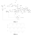
- the control module 15 controls the power switch units of the three phase bridge arms of the bridge arm converter 12 to work by using three-phase interleaved working time sequences shown in FIG. 6 , to control the charging power. That is, when the bridge arm converter 12 is working, with reference to the working time sequence diagram shown in FIG.
- the first control signal a controls the first power switch unit VT1 and the second power switch unit VT2 in the first phase bridge arm of the bridge arm converter 12 to be turned on or off, controls the first power switch unit VT1 to be turned on and the second power switch unit VT2 to be turned off when the first control signal a is at a high level, and controls the second power switch unit VT2 to be turned on and the first power switch unit VT1 to be turned off when the first control signal a is at a low level.
- the second control signal b controls the third power switch unit VT3 and the fourth power switch unit VT4 in the second phase bridge arm of the bridge arm converter 12 to be turned on or off, controls the third power switch unit VT3 to be turned on and the fourth power switch unit VT4 to be turned off when the second control signal b is at a high level, and controls the fourth power switch unit VT4 to be turned on and the third power switch unit VT3 to be turned off when the second control signal b is at a low level.
- the third control signal c controls the fifth power switch unit VT5 and the sixth power switch unit VT6 in the third phase bridge arm of the bridge arm converter 12 to be turned on or off, controls the fifth power switch unit VT5 to be turned on and the sixth power switch unit VT6 to be turned off when the third control signal c is at a high level, and controls the sixth power switch unit VT6 to be turned on and the fifth power switch unit VT5 to be turned off when the third control signal c is at a low level, to implement three-phase interleaved control of a bridge arm controller 120.
- the three phase bridge arms of the bridge arm converter are used in an out-of-phase manner, the inductance of the motor winding is fully utilized, the current flowing through the motor is controlled, and the preset quadrature axis and direct axis currents are set to zero, so that a corresponding charging power is completed and rotation of the motor is suppressed.
- the quadrature axis and direct axis currents and the zero-sequence current of the motor a function of charging by reusing the motor winding can be effectively completed, and the inductance of the motor winding is fully utilized, completing a charging function of an electric vehicle and suppressing output of a rotation torque of the motor.
- an inductance value of the motor winding can be fully used. Meanwhile, the direct-current side ripple can be effectively suppressed, and there is no need to add an additional inductor between the charging port and the motor coil, so that the circuit is simpler and costs are lower.
- an alternating current outputted by the alternating current power supply device has a part outputted to the bridge arm converter 12 through the motor coil 11 and the charging port 10 and a part outputted to the bidirectional bridge arm 13 through the external charging port 10, and the power battery 200 is charged under the joint action of the motor coil 11, the bridge arm converter 12, and the bidirectional bridge arm 13.
- this application further provides a power system including an energy conversion apparatus.
- the energy conversion apparatus further includes:
- This application further provides a vehicle including a power system.
- the power system in the vehicle provided in this embodiment of the present disclosure is the same as the foregoing power system. Therefore, for a specific working principle of the power system in the vehicle provided in this embodiment of the present disclosure, reference may be made to detailed descriptions of the foregoing power system, and details are not described herein again.
- an energy conversion apparatus including a motor coil and a bridge arm converter is used in a vehicle.
- the bridge arm converter is connected to an external battery and an external charging port, and the motor coil is connected to the external charging port; and a plurality of phase windings of the motor coil each include a plurality of coil units, first ends of the plurality of coil units in each phase winding are connected together and then connected to a plurality of phase bridge arms of the bridge arm converter in a one-to-one correspondence, and second ends of the plurality of coil units in each phase winding are connected to second ends of a plurality of coil units in other phase windings in a one-to-one correspondence and then selectively coupled to the external charging port.
- the plurality of coil units of the plurality of phase windings of the motor coil can be fully utilized, thereby improving a charging power and reducing a direct-current side ripple.
- the disclosed apparatus/terminal device and method may be implemented in other manners.
- the described apparatus/terminal device embodiment is merely schematic.
- the module/unit division is merely a logical function division and may be other division during actual implementation.
- a plurality of units or components may be combined or integrated into another system, or some features may be ignored or not performed.
- the displayed or discussed mutual couplings or direct couplings or communication connections may be implemented through some interfaces.
- the indirect couplings or communication connections between the apparatuses or units may be implemented in electronic, mechanical, or other forms.
- the units described as separate parts may or may not be physically separate. Parts displayed as units may or may not be physical units, and may be located at one position, or may be distributed on a plurality of network units. Some or all of the units may be selected according to actual needs to achieve the objectives of the solutions of the embodiments.
- functional units in the embodiments of this application may be integrated into one processing unit, or each of the units may exist alone physically, or two or more units may be integrated into one unit.
- the integrated unit may be implemented in a form of hardware, or may be implemented in a form of a software functional unit.
- the integrated module/unit When the integrated module/unit is implemented in the form of a software functional unit and sold or used as an independent product, the integrated unit may be stored in a computer-readable storage medium. Based on such understanding, all or some of the processes of the methods in the embodiments may be implemented by a computer program instructing relevant hardware.
- the computer program may be stored in a computer-readable storage medium. During execution of the computer program by the processor, steps of the foregoing method embodiments may be implemented.
- the computer program includes computer program code.
- the computer program code may be in source code form, object code form, executable file or some intermediate forms, or the like.
- the computer-readable medium may include: any entity or apparatus that is capable of carrying the computer program code, a recording medium, a USB flash drive, a removable hard disk, a magnetic disk, an optical disc, a read-only memory (ROM), a random access memory (RAM), an electric carrier signal, a telecommunication signal and a software distribution medium, and the like.
- the content contained in the computer-readable medium may be appropriately increased or decreased according to the requirements of legislation and patent practice in jurisdictions. For example, in some jurisdictions, according to legislation and patent practice, the computer-readable medium does not include an electric carrier signal and a telecommunication signal.
- orientation or position relationships indicated by the terms such as “center”, “longitudinal”, “transverse”, “length”, “width”, “thickness”, “on”, “below”, “front”, “back”, “left”, “right”, “vertical”, “horizontal”, “top”, “bottom”, “inside”, “outside”, “clockwise”, “anticlockwise”, “axial direction”, “radial direction”, and “circumferential direction” are based on orientation or position relationships shown in the accompanying drawings, and are used only for ease and brevity of illustration and description, rather than indicating or implying that the mentioned apparatus or component needs to have a particular orientation or needs to be constructed and operated in a particular orientation. Therefore, such terms should not be construed as limiting of this application.
- first and second are used merely for the purpose of description, and shall not be construed as indicating or implying relative importance or implying a quantity of indicated technical features. Therefore, features defining “first” and “second” may explicitly or implicitly include one or more such features. In descriptions of this application, "a plurality of” means two or more, unless otherwise defined clearly and specifically.
- connection may be a fixed connection, a detachable connection, or an integral connection; or the connection may be a mechanical connection or an electrical connection; or the connection may be a direct connection, an indirect connection through an intermediary, or internal communication between two components.
- the first feature being located “above” or “below” the second feature may be the first feature being in a direct contact with the second feature, or the first feature being in an indirect contact with the second feature through an intermediary.
- the first feature "over”, “above” and “up” the second feature may be that the first feature is directly above or obliquely above the second feature, or simply indicates that a horizontal height of the first feature is higher than that of the second feature.
- the first feature "under”, “below” and “down” the second feature may be that the first feature is directly below or obliquely below the second feature, or simply indicates that a horizontal height of the first feature is less than that of the second feature.
- references term such as "an embodiment”, “some embodiments”, “an example”, “a specific example”, or “some examples” means that a feature, structure, material, or characteristic that is described with reference to the embodiment or the example is included in at least one embodiment or example of this application.
- schematic representations of the above terms are not necessarily directed to the same embodiments or examples.
- the specific features, structures, materials, or characteristics described may be combined in any one or more embodiments or examples in a suitable manner.
- different embodiments or examples described in the present specification, as well as features of different embodiments or examples may be integrated and combined by those skilled in the art without contradicting each other.
Landscapes
- Engineering & Computer Science (AREA)
- Power Engineering (AREA)
- Transportation (AREA)
- Mechanical Engineering (AREA)
- Charge And Discharge Circuits For Batteries Or The Like (AREA)
- Electric Propulsion And Braking For Vehicles (AREA)
- Inverter Devices (AREA)
Claims (15)
- Energieumwandlungsvorrichtung, umfassend eine Motorspule bzw. Motorwicklung (11) und einen mit der Motorspule (11) verbundenen Brückenarmwandler (12), wobei:der Brückenarmwandler (12) mit einer externen Batterie (200) und einem externen Ladeanschluss (10) verbunden ist, die Motorspule (11) mit dem externen Ladeanschluss (10) verbunden ist, und der Brückenarmwandler (12) eine Vielzahl von Phasenbrückenarmen umfasst; unddie Motorwicklung (11) eine Vielzahl von Phasenwicklungen umfasst, jede Phasenwicklung N Spuleneinheiten umfasst, erste Enden der N Spuleneinheiten jeder Phasenwicklung miteinander verbunden sind und mit einem entsprechenden Phasenbrückenarm der Vielzahl von Phasenbrückenarmen verbunden sind, zweite Enden der N Spuleneinheiten in jeder Phasenwicklung jeweils mit zweiten Enden entsprechender Spuleneinheiten in anderen Phasenwicklungen verbunden sind, um N Neutralpunkte zu bilden, N Neutralleitungen von den N Neutralpunkten ausgehen und M Neutralleitungen von den N Neutralleitungen mit dem externen Ladeanschluss (10) verbunden sind, wobei N eine ganze Zahl größer als 1 ist und M eine ganze Zahl größer als 1 ist.
- Energieumwandlungsvorrichtung nach Anspruch 1, wobeidie Mehrzahl der Phasenbrückenarme des Brückenarmwandlers (12) einen ersten Phasenbrückenarm, einen zweiten Phasenbrückenarm und einen dritten Phasenbrückenarm umfasst;die mehreren Phasenwicklungen der Motorwicklung (11) dreiphasige Wicklungen umfassen; undjede dreiphasige Wicklung der Motorspule (11) umfasst N Spuleneinheiten, erste Enden der N Spuleneinheiten jeder dreiphasigen Wicklung sind miteinander verbunden und mit einem entsprechenden Phasenbrückenarm des Brückenarmwandlers (12) verbunden, zweite Enden der N Spuleneinheiten in jeder dreiphasigen Wicklung sind jeweils mit zweiten Enden entsprechender Spuleneinheiten in Wicklungen anderer zwei Phasen verbunden, um N Neutralpunkte zu bilden, wobei N Neutralleitungen von den N Neutralpunkten ausgehen und M Neutralleitungen von den N Neutralleitungen mit dem externen Ladeanschluss (10) verbunden sind, wobei N eine ganze Zahl größer als 1 ist und M eine ganze Zahl größer als 1 ist.
- Energieumwandlungsvorrichtung nach Anspruch 2, die ferner einen Schalter (14) umfasst, wobei der Schalter (14) mit den N Neutralleitungen verbunden ist und der Schalter (14) selektiv ein- oder ausgeschaltet wird, um die M Neutralleitungen in den N Neutralleitungen mit dem externen Ladeanschluss (10) zu verbinden.
- Energieumwandlungsvorrichtung nach Anspruch 3, die ferner ein Steuergerät bzw. eine Steuerung (15) umfasst, wobei das Steuergerät (15) mit dem Schalter (14) verbunden ist und das Steuergerät (15) dazu eingerichtet ist, den Schalter (14) so zu steuern, dass er selektiv ein- oder ausgeschaltet wird, damit die M Neutralleitungen von den N Neutralleitungen mit dem externen Ladeanschluss (10) verbunden werden.
- Energieumwandlungsvorrichtung nach Anspruch 4, wobei der Schalter (14) N Unterschalter umfasst, die N Unterschalter mit den N Neutralleitungen in einer Eins-zu-Eins-Entsprechung verbunden sind und die Steuerung (15) dazu eingerichtet ist, die N Unterschalter so zu steuern, dass sie ein- oder ausgeschaltet werden.
- Energieumwandlungsvorrichtung nach Anspruch 4, wobei die Steuerung (15) ferner eingerichtet ist zum:Erhalten dreiphasiger Steuersignale, wobei die dreiphasigen Steuersignale ein erstes Steuersignal, ein zweites Steuersignal und ein drittes Steuersignal umfassen, die sich der Reihe nach um eine vorgegebene Phase unterscheiden; undabwechselndes Einschalten von zwei Leistungsschaltern des ersten Phasenbrückenarms des Brückenarmwandlers (12) gemäß dem ersten Steuersignal, abwechselndes Einschalten von zwei Leistungsschaltern des zweiten Phasenbrückenarms des Brückenarmwandlers (12) gemäß dem zweiten Steuersignal und abwechselndes Einschalten von zwei Leistungsschaltern des dritten Phasenbrückenarms des Brückenarmwandlers (12) gemäß dem dritten Steuersignal, um die externe Batterie (200) zu beladen.
- Energieumwandlungsvorrichtung nach Anspruch 6, wobei die Steuerung (15) ferner dazu eingerichtet ist:ein Rotorwinkelsignal, dreiphasige Ladeströme, einen voreingestellten Quadraturachsenstrom, einen voreingestellten Gleichachsenstrom, eine Vorwärtsspannung und eine busseitige Gleichspannung eines Motors in einem Lademodus zu erhalten;dreiphasige Modulationssignale entsprechend dem Rotorwinkelsignal, den dreiphasigen Ladeströmen, dem voreingestellten Quadraturachsenstrom, dem voreingestellten Gleichachsenstrom, der Vorwärtsspannung und der busseitigen Gleichspannung zu erhalten; undein voreingestelltes Trägersignal zu erhalten, und die dreiphasigen Steuersignale zu erhalten, die sich um die voreingestellte Phase entsprechend dem Trägersignal und den dreiphasigen Modulationssignalen unterscheiden.
- Energieumwandlungsvorrichtung nach Anspruch 7, wobei die Steuerung (15) ferner dazu eingerichtet ist:ein erstes Modulationssignal entsprechend dem Rotorwinkelsignal, den dreiphasigen Ladeströmen, dem voreingestellten Quadraturachsenstrom, dem voreingestellten Gleichachsenstrom und der busseitigen Gleichspannung zu erhalten;ein zweites Modulationssignal in Abhängigkeit von den dreiphasigen Ladeströmen und der Vorwärtsspannung zu erhalten; unddie dreiphasigen Modulationssignale entsprechend dem ersten Modulationssignal und dem zweiten Modulationssignal zu erhalten.
- Energieumwandlungsvorrichtung nach Anspruch 8, wobei die Steuerung (15) ferner dazu eingerichtet ist:eine Koordinatentransformation der dreiphasigen Ladeströme entsprechend dem Rotorwinkelsignal durchführen, um zweiphasige Ladeströme zu erhalten;eine Quadraturachsen-Spannung und eine Gleichachsen-Spannung durch eine Stromregelung zu erhalten, nachdem Differenzen zwischen den zweiphasigen Ladeströmen und dem voreingestellten Quadraturachsen-Strom und dem voreingestellten Gleichachsen-Strom berechnet wurden; unddas erste Modulationssignal entsprechend dem Rotorwinkelsignal, der Quadraturachsspannung, der Achsgleichspannung und der busseitigen Gleichspannung zu erhalten.
- Energieumwandlungsvorrichtung nach Anspruch 7, wobei die Steuerung (15) ferner dazu eingerichtet ist:
den voreingestellten Strom der Quadraturachse und den voreingestellten Strom der Gleichachse einzustellen, damit das Ausgangsdrehmoment Null ist. - Energieumwandlungsvorrichtung nach Anspruch 8, wobei die Steuerung (15) ferner dazu eingerichtet ist:aus den dreiphasigen Ladeströmen einen Nullstrom zu gewinnen;eine Modulationsspannung durch eine Stromregelung zu erhalten, nachdem eine Differenz zwischen dem Nullstrom und einem vorgegebenen Ladestrom berechnet wurde, wobei der vorgegebene Ladestrom durch Analyse einer Instruktion erhalten wird; unddas zweite Modulationssignal durch eine Spannungsregelung zu erhalten, nachdem eine Summe aus der Modulationsspannung und der Vorwärtsspannung berechnet wurde.
- Energieumwandlungsvorrichtung nach Anspruch 8, wobei die Steuerung (15) ferner eingerichtet ist zum:
Addieren eines Tastverhältnisses des zweiten Modulationssignals und eines Tastverhältnisses des ersten Modulationssignals, um die dreiphasigen Modulationssignale zu erhalten. - Energieumwandlungsvorrichtung nach Anspruch 12, wobeidas Trägersignal ein erstphasiges Trägersignal, ein zweitphasiges Trägersignal und ein drittphasiges Trägersignal umfasst; die dreiphasigen Modulationssignale ein erstphasiges Modulationssignal, ein zweitphasiges Modulationssignal und ein drittphasiges Modulationssignal umfassen; und eine Phase des erstphasigen Trägersignals, eine Phase des zweitphasigen Trägersignals und eine Phase des drittphasigen Trägersignals sich um einen ersten voreingestellten Winkel in Folge unterscheiden, oder eine Phase des erstphasigen Modulationssignals, eine Phase des zweitphasigen Modulationssignals und eine Phase des drittphasigen Modulationssignals sich um einen zweiten voreingestellten Winkel in Folge unterscheiden; und wobeider Controller ist dazu eingerichtet ist:
das Trägersignal der ersten Phase und das Modulationssignal der ersten Phase zu überlagern, das Trägersignal der zweiten Phase und das Modulationssignal der zweiten Phase zu überlagern und das Trägersignal der dritten Phase und das Modulationssignal der dritten Phase zu überlagern, um die dreiphasigen Steuersignale zu erhalten. - Antriebssystem, das die Energieumwandlungsvorrichtung nach einem der Ansprüche 1 bis 13 umfasst, wobei die Energieumwandlungsvorrichtung ferner umfasst:einen Motor, der die Motorspule (11) umfasst, wobei die Motorspule (11) mit dem externen Ladeanschluss (10) verbunden ist;eine Motorsteuerung, die den Brückenarmwandler umfasst, wobei der Brückenarmwandler (12) mit der Motorspule (11) verbunden ist; undein Fahrzeugladegerät, das den bidirektionalen Brückenarm umfasst, wobei der bidirektionale Brückenarm parallel mit dem Brückenarmwandler (12) verbunden ist, um ein erstes gemeinsames Verbindungsende und ein zweites gemeinsames Verbindungsende zu bilden, wobei das erste gemeinsame Verbindungsende mit einem ersten Ende der externen Batterie (200) verbunden ist, das zweite gemeinsame Verbindungsende mit einem zweiten Ende der externen Batterie (200) verbunden ist, und der externe Ladeanschluss (10) mit dem zweiten gemeinsamen Verbindungsende und dem bidirektionalen Brückenarm verbunden ist.
- Fahrzeug, das das Antriebssystem nach Anspruch 14 umfasst.
Applications Claiming Priority (2)
| Application Number | Priority Date | Filing Date | Title |
|---|---|---|---|
| CN201910582147.9A CN111434512B (zh) | 2019-06-30 | 2019-06-30 | 一种能量转换装置、动力系统及车辆 |
| PCT/CN2020/096819 WO2021000739A1 (zh) | 2019-06-30 | 2020-06-18 | 一种能量转换装置、动力系统及车辆 |
Publications (3)
| Publication Number | Publication Date |
|---|---|
| EP3992020A1 EP3992020A1 (de) | 2022-05-04 |
| EP3992020A4 EP3992020A4 (de) | 2023-05-31 |
| EP3992020B1 true EP3992020B1 (de) | 2024-09-11 |
Family
ID=71580104
Family Applications (1)
| Application Number | Title | Priority Date | Filing Date |
|---|---|---|---|
| EP20835108.0A Active EP3992020B1 (de) | 2019-06-30 | 2020-06-18 | Energieumwandlungsvorrichtung, leistungssystem und fahrzeug |
Country Status (7)
| Country | Link |
|---|---|
| US (1) | US11996781B2 (de) |
| EP (1) | EP3992020B1 (de) |
| JP (1) | JP7313532B2 (de) |
| CN (1) | CN111434512B (de) |
| ES (1) | ES2989595T3 (de) |
| HU (1) | HUE069134T2 (de) |
| WO (1) | WO2021000739A1 (de) |
Families Citing this family (10)
| Publication number | Priority date | Publication date | Assignee | Title |
|---|---|---|---|---|
| CN111873830B (zh) * | 2020-09-11 | 2022-10-25 | 北京理工大学 | 一种用于电动汽车的分布式双电机驱动与车载充电集成系统及其充电控制方法 |
| CN115051616A (zh) * | 2021-03-09 | 2022-09-13 | 上海蔚兰动力科技有限公司 | 一种车辆控制方法及车辆驱动系统 |
| WO2023004673A1 (zh) * | 2021-07-29 | 2023-02-02 | 宁德时代新能源科技股份有限公司 | 电池充电的方法、电池管理系统和充放电装置 |
| CN113844297A (zh) * | 2021-09-19 | 2021-12-28 | 浙江大学 | 一种电动汽车三相集成充电器的零转矩充电方法 |
| CN114211981B (zh) * | 2021-11-01 | 2023-12-15 | 华为数字能源技术有限公司 | 一种电机驱动系统、车辆、充电方法、控制装置及介质 |
| CN114465335B (zh) * | 2022-01-25 | 2025-05-23 | 华为数字能源技术有限公司 | 能量转换系统及动力系统 |
| CN115366705B (zh) * | 2022-04-22 | 2024-03-22 | 宁德时代新能源科技股份有限公司 | 充放电电路的控制方法、装置、设备、系统及存储介质 |
| CN115520045B (zh) * | 2022-09-22 | 2025-05-06 | 华为数字能源技术有限公司 | 一种供电模块、车辆互充的供电控制方法及车辆 |
| CN116404944A (zh) * | 2023-03-06 | 2023-07-07 | 华为数字能源技术有限公司 | 一种动力总成、控制器及混合动力汽车 |
| DE102023119737A1 (de) | 2023-07-26 | 2025-01-30 | Dr. Ing. H.C. F. Porsche Aktiengesellschaft | Vorrichtung mit einer Elektromaschine und einer Batterieanordnung |
Family Cites Families (21)
| Publication number | Priority date | Publication date | Assignee | Title |
|---|---|---|---|---|
| US5182508A (en) * | 1992-04-16 | 1993-01-26 | Westinghouse Electric Corp. | Reconfigurable AC induction motor drive for battery-powered vehicle |
| JP4679891B2 (ja) * | 2004-11-30 | 2011-05-11 | トヨタ自動車株式会社 | 交流電圧発生装置および動力出力装置 |
| US7733039B2 (en) * | 2006-10-19 | 2010-06-08 | Ut-Battelle, Llc | Electric vehicle system for charging and supplying electrical power |
| JP5288178B2 (ja) * | 2008-02-28 | 2013-09-11 | 富士電機株式会社 | モータ駆動システム |
| FR2973963B1 (fr) * | 2011-04-08 | 2013-04-12 | Valeo Sys Controle Moteur Sas | Dispositif de transfert de charge et procede de gestion associe |
| US20140097792A1 (en) * | 2012-10-04 | 2014-04-10 | Ut-Battelle, Llc | Electric vehicle recharging and or supplying electrical power |
| DE102012218512A1 (de) * | 2012-10-11 | 2014-04-17 | Robert Bosch Gmbh | Vorrichtung und Verfahren zum Laden eines elektrischen Energiespeichers aus einer dreiphasigen Wechselspannungsquelle |
| JP2014161142A (ja) * | 2013-02-19 | 2014-09-04 | Nissan Motor Co Ltd | 充電装置、充電方法及びモータ駆動方法 |
| FR3002384B1 (fr) | 2013-02-21 | 2016-08-19 | Valeo Systemes De Controle Moteur | Architecture electrique pour la conversion d'une tension continue en une tension alternative, et reciproquement |
| US20140265971A1 (en) * | 2013-03-12 | 2014-09-18 | Kollmorgen Corporation | Battery Charger/Export Power |
| CN103684202B (zh) | 2013-12-27 | 2016-09-14 | 大洋电机新动力科技有限公司 | 集成驱动及充放电功能的电机控制器 |
| CN104092273B (zh) * | 2014-07-25 | 2017-01-18 | 中山大洋电机股份有限公司 | 电动汽车驱动与充电集成控制方法及其应用的电动汽车 |
| FR3024604B1 (fr) * | 2014-08-01 | 2019-08-16 | Renault S.A.S | Chargeur et procede de charge de batterie de vehicule automobile electrique ou hybride a machine a reluctance variable a double saillance. |
| CN110266243B (zh) * | 2015-02-25 | 2023-04-07 | 日立三菱水力株式会社 | 可变速发电电动系统 |
| CN105743175B (zh) * | 2016-04-07 | 2018-02-02 | 东南大学 | 一种集成充电机功能的电动车驱动系统 |
| DE102016209898A1 (de) * | 2016-06-06 | 2017-12-07 | Continental Automotive Gmbh | Fahrzeugbordnetz mit Wechselrichter, Energiespeicher, elektrischer Maschine und Gleichstrom-Übertragungsanschluss |
| CN107134839A (zh) * | 2017-05-11 | 2017-09-05 | 山东鲁能智能技术有限公司 | 一种基于全数字控制的高功率密度充电模块及方法 |
| CN109713738A (zh) * | 2017-10-25 | 2019-05-03 | 河南森源重工有限公司 | 一种集成驱动和充电功能的容错电路 |
| KR102063921B1 (ko) * | 2017-12-13 | 2020-01-08 | 현대오트론 주식회사 | 차량용 전력 제어 장치 |
| CN109672240B (zh) * | 2018-12-19 | 2020-11-03 | 山东大学 | 插电式混合电动汽车充电系统、方法及应用 |
| CN111434513B (zh) | 2019-06-30 | 2021-02-23 | 比亚迪股份有限公司 | 一种车辆及其能量转换装置与动力系统 |
-
2019
- 2019-06-30 CN CN201910582147.9A patent/CN111434512B/zh active Active
-
2020
- 2020-06-18 JP JP2022500063A patent/JP7313532B2/ja active Active
- 2020-06-18 US US17/622,188 patent/US11996781B2/en active Active
- 2020-06-18 EP EP20835108.0A patent/EP3992020B1/de active Active
- 2020-06-18 HU HUE20835108A patent/HUE069134T2/hu unknown
- 2020-06-18 WO PCT/CN2020/096819 patent/WO2021000739A1/zh not_active Ceased
- 2020-06-18 ES ES20835108T patent/ES2989595T3/es active Active
Also Published As
| Publication number | Publication date |
|---|---|
| CN111434512B (zh) | 2021-01-01 |
| HUE069134T2 (hu) | 2025-02-28 |
| US20220360183A1 (en) | 2022-11-10 |
| EP3992020A4 (de) | 2023-05-31 |
| WO2021000739A1 (zh) | 2021-01-07 |
| ES2989595T3 (es) | 2024-11-27 |
| CN111434512A (zh) | 2020-07-21 |
| EP3992020A1 (de) | 2022-05-04 |
| US11996781B2 (en) | 2024-05-28 |
| JP7313532B2 (ja) | 2023-07-24 |
| JP2022540573A (ja) | 2022-09-16 |
Similar Documents
| Publication | Publication Date | Title |
|---|---|---|
| EP3992020B1 (de) | Energieumwandlungsvorrichtung, leistungssystem und fahrzeug | |
| JP7839853B2 (ja) | 動力電池の充電方法、モータ制御回路及び車両 | |
| KR102565333B1 (ko) | 모터 구동 시스템을 이용한 충전 시스템의 제어 장치 | |
| JP7613905B2 (ja) | 制御装置、プログラム、及び制御方法 | |
| CN101953065B (zh) | 电动机驱动控制装置 | |
| US8264181B2 (en) | Controller for motor drive control system | |
| US8639405B2 (en) | Electric motor drive system for an electric vehicle | |
| US9950627B2 (en) | Power conversion device | |
| US20110279071A1 (en) | Control device for ac motor | |
| CN112440767B (zh) | 充电控制方法、系统及其存储介质 | |
| CN113285648A (zh) | 驱动充电集成电路、电动汽车及其控制方法和控制系统 | |
| JP5534323B2 (ja) | 電動機制御装置 | |
| WO2021000741A1 (zh) | 充电控制方法、装置、电路拓扑、能量转换装置及车辆 | |
| US12413169B2 (en) | Power conversion apparatus | |
| WO2018117084A1 (ja) | 電力変換装置 | |
| JP2015109770A (ja) | 電動機駆動装置 | |
| JP2012135141A (ja) | モータ駆動システム | |
| JP5210822B2 (ja) | 交流電動機の制御装置およびそれを搭載した電動車両 | |
| US8148927B2 (en) | Alternating-current motor control apparatus | |
| JP7574657B2 (ja) | 交流電動機の制御装置 | |
| US20250373179A1 (en) | Power conversion device and program product | |
| JP5705677B2 (ja) | 回転電機制御システム | |
| CN119382576A (zh) | 一种集成母线升压与开路故障容错功能的三相电驱动系统 | |
| WO2022138209A1 (ja) | 変圧装置 |
Legal Events
| Date | Code | Title | Description |
|---|---|---|---|
| STAA | Information on the status of an ep patent application or granted ep patent |
Free format text: STATUS: THE INTERNATIONAL PUBLICATION HAS BEEN MADE |
|
| PUAI | Public reference made under article 153(3) epc to a published international application that has entered the european phase |
Free format text: ORIGINAL CODE: 0009012 |
|
| STAA | Information on the status of an ep patent application or granted ep patent |
Free format text: STATUS: REQUEST FOR EXAMINATION WAS MADE |
|
| 17P | Request for examination filed |
Effective date: 20220124 |
|
| AK | Designated contracting states |
Kind code of ref document: A1 Designated state(s): AL AT BE BG CH CY CZ DE DK EE ES FI FR GB GR HR HU IE IS IT LI LT LU LV MC MK MT NL NO PL PT RO RS SE SI SK SM TR |
|
| DAV | Request for validation of the european patent (deleted) | ||
| DAX | Request for extension of the european patent (deleted) | ||
| A4 | Supplementary search report drawn up and despatched |
Effective date: 20230503 |
|
| RIC1 | Information provided on ipc code assigned before grant |
Ipc: H02J 7/00 20060101ALI20230425BHEP Ipc: H02J 7/02 20160101ALI20230425BHEP Ipc: B60L 53/24 20190101ALI20230425BHEP Ipc: B60L 53/22 20190101AFI20230425BHEP |
|
| GRAP | Despatch of communication of intention to grant a patent |
Free format text: ORIGINAL CODE: EPIDOSNIGR1 |
|
| STAA | Information on the status of an ep patent application or granted ep patent |
Free format text: STATUS: GRANT OF PATENT IS INTENDED |
|
| INTG | Intention to grant announced |
Effective date: 20240423 |
|
| GRAS | Grant fee paid |
Free format text: ORIGINAL CODE: EPIDOSNIGR3 |
|
| GRAA | (expected) grant |
Free format text: ORIGINAL CODE: 0009210 |
|
| STAA | Information on the status of an ep patent application or granted ep patent |
Free format text: STATUS: THE PATENT HAS BEEN GRANTED |
|
| AK | Designated contracting states |
Kind code of ref document: B1 Designated state(s): AL AT BE BG CH CY CZ DE DK EE ES FI FR GB GR HR HU IE IS IT LI LT LU LV MC MK MT NL NO PL PT RO RS SE SI SK SM TR |
|
| REG | Reference to a national code |
Ref country code: GB Ref legal event code: FG4D |
|
| REG | Reference to a national code |
Ref country code: CH Ref legal event code: EP |
|
| REG | Reference to a national code |
Ref country code: DE Ref legal event code: R096 Ref document number: 602020037679 Country of ref document: DE |
|
| REG | Reference to a national code |
Ref country code: NL Ref legal event code: FP Ref country code: IE Ref legal event code: FG4D |
|
| REG | Reference to a national code |
Ref country code: ES Ref legal event code: FG2A Ref document number: 2989595 Country of ref document: ES Kind code of ref document: T3 Effective date: 20241127 |
|
| P01 | Opt-out of the competence of the unified patent court (upc) registered |
Free format text: CASE NUMBER: APP_63234/2024 Effective date: 20241128 |
|
| REG | Reference to a national code |
Ref country code: LT Ref legal event code: MG9D |
|
| PG25 | Lapsed in a contracting state [announced via postgrant information from national office to epo] |
Ref country code: NO Free format text: LAPSE BECAUSE OF FAILURE TO SUBMIT A TRANSLATION OF THE DESCRIPTION OR TO PAY THE FEE WITHIN THE PRESCRIBED TIME-LIMIT Effective date: 20241211 |
|
| PG25 | Lapsed in a contracting state [announced via postgrant information from national office to epo] |
Ref country code: GR Free format text: LAPSE BECAUSE OF FAILURE TO SUBMIT A TRANSLATION OF THE DESCRIPTION OR TO PAY THE FEE WITHIN THE PRESCRIBED TIME-LIMIT Effective date: 20241212 Ref country code: FI Free format text: LAPSE BECAUSE OF FAILURE TO SUBMIT A TRANSLATION OF THE DESCRIPTION OR TO PAY THE FEE WITHIN THE PRESCRIBED TIME-LIMIT Effective date: 20240911 |
|
| PG25 | Lapsed in a contracting state [announced via postgrant information from national office to epo] |
Ref country code: BG Free format text: LAPSE BECAUSE OF FAILURE TO SUBMIT A TRANSLATION OF THE DESCRIPTION OR TO PAY THE FEE WITHIN THE PRESCRIBED TIME-LIMIT Effective date: 20240911 |
|
| PG25 | Lapsed in a contracting state [announced via postgrant information from national office to epo] |
Ref country code: LV Free format text: LAPSE BECAUSE OF FAILURE TO SUBMIT A TRANSLATION OF THE DESCRIPTION OR TO PAY THE FEE WITHIN THE PRESCRIBED TIME-LIMIT Effective date: 20240911 |
|
| PG25 | Lapsed in a contracting state [announced via postgrant information from national office to epo] |
Ref country code: HR Free format text: LAPSE BECAUSE OF FAILURE TO SUBMIT A TRANSLATION OF THE DESCRIPTION OR TO PAY THE FEE WITHIN THE PRESCRIBED TIME-LIMIT Effective date: 20240911 |
|
| PG25 | Lapsed in a contracting state [announced via postgrant information from national office to epo] |
Ref country code: RS Free format text: LAPSE BECAUSE OF FAILURE TO SUBMIT A TRANSLATION OF THE DESCRIPTION OR TO PAY THE FEE WITHIN THE PRESCRIBED TIME-LIMIT Effective date: 20241211 |
|
| PG25 | Lapsed in a contracting state [announced via postgrant information from national office to epo] |
Ref country code: RS Free format text: LAPSE BECAUSE OF FAILURE TO SUBMIT A TRANSLATION OF THE DESCRIPTION OR TO PAY THE FEE WITHIN THE PRESCRIBED TIME-LIMIT Effective date: 20241211 Ref country code: NO Free format text: LAPSE BECAUSE OF FAILURE TO SUBMIT A TRANSLATION OF THE DESCRIPTION OR TO PAY THE FEE WITHIN THE PRESCRIBED TIME-LIMIT Effective date: 20241211 Ref country code: LV Free format text: LAPSE BECAUSE OF FAILURE TO SUBMIT A TRANSLATION OF THE DESCRIPTION OR TO PAY THE FEE WITHIN THE PRESCRIBED TIME-LIMIT Effective date: 20240911 Ref country code: HR Free format text: LAPSE BECAUSE OF FAILURE TO SUBMIT A TRANSLATION OF THE DESCRIPTION OR TO PAY THE FEE WITHIN THE PRESCRIBED TIME-LIMIT Effective date: 20240911 Ref country code: GR Free format text: LAPSE BECAUSE OF FAILURE TO SUBMIT A TRANSLATION OF THE DESCRIPTION OR TO PAY THE FEE WITHIN THE PRESCRIBED TIME-LIMIT Effective date: 20241212 Ref country code: FI Free format text: LAPSE BECAUSE OF FAILURE TO SUBMIT A TRANSLATION OF THE DESCRIPTION OR TO PAY THE FEE WITHIN THE PRESCRIBED TIME-LIMIT Effective date: 20240911 Ref country code: BG Free format text: LAPSE BECAUSE OF FAILURE TO SUBMIT A TRANSLATION OF THE DESCRIPTION OR TO PAY THE FEE WITHIN THE PRESCRIBED TIME-LIMIT Effective date: 20240911 |
|
| REG | Reference to a national code |
Ref country code: AT Ref legal event code: MK05 Ref document number: 1722420 Country of ref document: AT Kind code of ref document: T Effective date: 20240911 |
|
| REG | Reference to a national code |
Ref country code: HU Ref legal event code: AG4A Ref document number: E069134 Country of ref document: HU |
|
| PG25 | Lapsed in a contracting state [announced via postgrant information from national office to epo] |
Ref country code: IS Free format text: LAPSE BECAUSE OF FAILURE TO SUBMIT A TRANSLATION OF THE DESCRIPTION OR TO PAY THE FEE WITHIN THE PRESCRIBED TIME-LIMIT Effective date: 20250111 Ref country code: PT Free format text: LAPSE BECAUSE OF FAILURE TO SUBMIT A TRANSLATION OF THE DESCRIPTION OR TO PAY THE FEE WITHIN THE PRESCRIBED TIME-LIMIT Effective date: 20250113 |
|
| PG25 | Lapsed in a contracting state [announced via postgrant information from national office to epo] |
Ref country code: RO Free format text: LAPSE BECAUSE OF FAILURE TO SUBMIT A TRANSLATION OF THE DESCRIPTION OR TO PAY THE FEE WITHIN THE PRESCRIBED TIME-LIMIT Effective date: 20240911 Ref country code: SM Free format text: LAPSE BECAUSE OF FAILURE TO SUBMIT A TRANSLATION OF THE DESCRIPTION OR TO PAY THE FEE WITHIN THE PRESCRIBED TIME-LIMIT Effective date: 20240911 |
|
| PG25 | Lapsed in a contracting state [announced via postgrant information from national office to epo] |
Ref country code: EE Free format text: LAPSE BECAUSE OF FAILURE TO SUBMIT A TRANSLATION OF THE DESCRIPTION OR TO PAY THE FEE WITHIN THE PRESCRIBED TIME-LIMIT Effective date: 20240911 Ref country code: AT Free format text: LAPSE BECAUSE OF FAILURE TO SUBMIT A TRANSLATION OF THE DESCRIPTION OR TO PAY THE FEE WITHIN THE PRESCRIBED TIME-LIMIT Effective date: 20240911 |
|
| PG25 | Lapsed in a contracting state [announced via postgrant information from national office to epo] |
Ref country code: PL Free format text: LAPSE BECAUSE OF FAILURE TO SUBMIT A TRANSLATION OF THE DESCRIPTION OR TO PAY THE FEE WITHIN THE PRESCRIBED TIME-LIMIT Effective date: 20240911 Ref country code: CZ Free format text: LAPSE BECAUSE OF FAILURE TO SUBMIT A TRANSLATION OF THE DESCRIPTION OR TO PAY THE FEE WITHIN THE PRESCRIBED TIME-LIMIT Effective date: 20240911 |
|
| PG25 | Lapsed in a contracting state [announced via postgrant information from national office to epo] |
Ref country code: SK Free format text: LAPSE BECAUSE OF FAILURE TO SUBMIT A TRANSLATION OF THE DESCRIPTION OR TO PAY THE FEE WITHIN THE PRESCRIBED TIME-LIMIT Effective date: 20240911 |
|
| REG | Reference to a national code |
Ref country code: DE Ref legal event code: R097 Ref document number: 602020037679 Country of ref document: DE |
|
| PGFP | Annual fee paid to national office [announced via postgrant information from national office to epo] |
Ref country code: DE Payment date: 20250618 Year of fee payment: 6 |
|
| PG25 | Lapsed in a contracting state [announced via postgrant information from national office to epo] |
Ref country code: DK Free format text: LAPSE BECAUSE OF FAILURE TO SUBMIT A TRANSLATION OF THE DESCRIPTION OR TO PAY THE FEE WITHIN THE PRESCRIBED TIME-LIMIT Effective date: 20240911 |
|
| PGFP | Annual fee paid to national office [announced via postgrant information from national office to epo] |
Ref country code: GB Payment date: 20250618 Year of fee payment: 6 |
|
| PGFP | Annual fee paid to national office [announced via postgrant information from national office to epo] |
Ref country code: NL Payment date: 20250618 Year of fee payment: 6 |
|
| PGFP | Annual fee paid to national office [announced via postgrant information from national office to epo] |
Ref country code: HU Payment date: 20250620 Year of fee payment: 6 Ref country code: FR Payment date: 20250627 Year of fee payment: 6 |
|
| PLBE | No opposition filed within time limit |
Free format text: ORIGINAL CODE: 0009261 |
|
| STAA | Information on the status of an ep patent application or granted ep patent |
Free format text: STATUS: NO OPPOSITION FILED WITHIN TIME LIMIT |
|
| 26N | No opposition filed |
Effective date: 20250612 |
|
| PG25 | Lapsed in a contracting state [announced via postgrant information from national office to epo] |
Ref country code: SE Free format text: LAPSE BECAUSE OF FAILURE TO SUBMIT A TRANSLATION OF THE DESCRIPTION OR TO PAY THE FEE WITHIN THE PRESCRIBED TIME-LIMIT Effective date: 20240911 |
|
| PGFP | Annual fee paid to national office [announced via postgrant information from national office to epo] |
Ref country code: ES Payment date: 20250731 Year of fee payment: 6 |
|
| PGFP | Annual fee paid to national office [announced via postgrant information from national office to epo] |
Ref country code: IT Payment date: 20250624 Year of fee payment: 6 |
|
| REG | Reference to a national code |
Ref country code: CH Ref legal event code: H13 Free format text: ST27 STATUS EVENT CODE: U-0-0-H10-H13 (AS PROVIDED BY THE NATIONAL OFFICE) Effective date: 20260127 |
|
| PG25 | Lapsed in a contracting state [announced via postgrant information from national office to epo] |
Ref country code: MC Free format text: LAPSE BECAUSE OF FAILURE TO SUBMIT A TRANSLATION OF THE DESCRIPTION OR TO PAY THE FEE WITHIN THE PRESCRIBED TIME-LIMIT Effective date: 20240911 |
|
| PG25 | Lapsed in a contracting state [announced via postgrant information from national office to epo] |
Ref country code: LU Free format text: LAPSE BECAUSE OF NON-PAYMENT OF DUE FEES Effective date: 20250618 |
|
| REG | Reference to a national code |
Ref country code: BE Ref legal event code: MM Effective date: 20250630 |
|
| PG25 | Lapsed in a contracting state [announced via postgrant information from national office to epo] |
Ref country code: IE Free format text: LAPSE BECAUSE OF NON-PAYMENT OF DUE FEES Effective date: 20250618 |
|
| PG25 | Lapsed in a contracting state [announced via postgrant information from national office to epo] |
Ref country code: BE Free format text: LAPSE BECAUSE OF NON-PAYMENT OF DUE FEES Effective date: 20250630 |