EP3991971A1 - Plate pressing type laminator and pressure applying method - Google Patents
Plate pressing type laminator and pressure applying method Download PDFInfo
- Publication number
- EP3991971A1 EP3991971A1 EP21171807.7A EP21171807A EP3991971A1 EP 3991971 A1 EP3991971 A1 EP 3991971A1 EP 21171807 A EP21171807 A EP 21171807A EP 3991971 A1 EP3991971 A1 EP 3991971A1
- Authority
- EP
- European Patent Office
- Prior art keywords
- plate
- shaped pressing
- pressing member
- shaped
- layer
- Prior art date
- Legal status (The legal status is an assumption and is not a legal conclusion. Google has not performed a legal analysis and makes no representation as to the accuracy of the status listed.)
- Pending
Links
- 238000003825 pressing Methods 0.000 title claims abstract description 451
- 238000000034 method Methods 0.000 title claims abstract description 23
- 238000007789 sealing Methods 0.000 claims description 68
- 238000010438 heat treatment Methods 0.000 claims description 20
- 238000001816 cooling Methods 0.000 claims description 11
- 230000001360 synchronised effect Effects 0.000 claims description 5
- 238000003475 lamination Methods 0.000 abstract description 62
- 239000012528 membrane Substances 0.000 abstract description 24
- 238000010030 laminating Methods 0.000 abstract description 5
- 238000004519 manufacturing process Methods 0.000 description 15
- 238000004891 communication Methods 0.000 description 14
- 230000005540 biological transmission Effects 0.000 description 11
- 230000005484 gravity Effects 0.000 description 11
- 239000004744 fabric Substances 0.000 description 6
- 238000010586 diagram Methods 0.000 description 5
- 230000008569 process Effects 0.000 description 5
- 239000002131 composite material Substances 0.000 description 4
- 238000007731 hot pressing Methods 0.000 description 4
- 230000008901 benefit Effects 0.000 description 3
- 230000000694 effects Effects 0.000 description 3
- 239000011521 glass Substances 0.000 description 3
- 230000008859 change Effects 0.000 description 2
- 239000011888 foil Substances 0.000 description 2
- 239000003292 glue Substances 0.000 description 2
- 239000000463 material Substances 0.000 description 2
- 230000001174 ascending effect Effects 0.000 description 1
- 230000006835 compression Effects 0.000 description 1
- 238000007906 compression Methods 0.000 description 1
- 239000002826 coolant Substances 0.000 description 1
- 230000007547 defect Effects 0.000 description 1
- 238000013461 design Methods 0.000 description 1
- 238000011161 development Methods 0.000 description 1
- 238000005516 engineering process Methods 0.000 description 1
- 230000002349 favourable effect Effects 0.000 description 1
- 230000007246 mechanism Effects 0.000 description 1
- 230000002093 peripheral effect Effects 0.000 description 1
- 238000004321 preservation Methods 0.000 description 1
- 230000009467 reduction Effects 0.000 description 1
- 230000000717 retained effect Effects 0.000 description 1
- 238000000926 separation method Methods 0.000 description 1
- 230000008961 swelling Effects 0.000 description 1
- 238000012546 transfer Methods 0.000 description 1
Images


Classifications
-
- B—PERFORMING OPERATIONS; TRANSPORTING
- B32—LAYERED PRODUCTS
- B32B—LAYERED PRODUCTS, i.e. PRODUCTS BUILT-UP OF STRATA OF FLAT OR NON-FLAT, e.g. CELLULAR OR HONEYCOMB, FORM
- B32B37/00—Methods or apparatus for laminating, e.g. by curing or by ultrasonic bonding
- B32B37/0046—Methods or apparatus for laminating, e.g. by curing or by ultrasonic bonding characterised by constructional aspects of the apparatus
- B32B37/0053—Constructional details of laminating machines comprising rollers; Constructional features of the rollers
-
- B—PERFORMING OPERATIONS; TRANSPORTING
- B30—PRESSES
- B30B—PRESSES IN GENERAL
- B30B1/00—Presses, using a press ram, characterised by the features of the drive therefor, pressure being transmitted directly, or through simple thrust or tension members only, to the press ram or platen
- B30B1/32—Presses, using a press ram, characterised by the features of the drive therefor, pressure being transmitted directly, or through simple thrust or tension members only, to the press ram or platen by plungers under fluid pressure
- B30B1/38—Presses, using a press ram, characterised by the features of the drive therefor, pressure being transmitted directly, or through simple thrust or tension members only, to the press ram or platen by plungers under fluid pressure wherein the plungers are operated by pressure of a gas, e.g. steam, air
-
- B—PERFORMING OPERATIONS; TRANSPORTING
- B30—PRESSES
- B30B—PRESSES IN GENERAL
- B30B15/00—Details of, or accessories for, presses; Auxiliary measures in connection with pressing
-
- B—PERFORMING OPERATIONS; TRANSPORTING
- B30—PRESSES
- B30B—PRESSES IN GENERAL
- B30B15/00—Details of, or accessories for, presses; Auxiliary measures in connection with pressing
- B30B15/06—Platens or press rams
- B30B15/061—Cushion plates
-
- B—PERFORMING OPERATIONS; TRANSPORTING
- B30—PRESSES
- B30B—PRESSES IN GENERAL
- B30B15/00—Details of, or accessories for, presses; Auxiliary measures in connection with pressing
- B30B15/06—Platens or press rams
- B30B15/062—Press plates
-
- B—PERFORMING OPERATIONS; TRANSPORTING
- B30—PRESSES
- B30B—PRESSES IN GENERAL
- B30B15/00—Details of, or accessories for, presses; Auxiliary measures in connection with pressing
- B30B15/34—Heating or cooling presses or parts thereof
-
- B—PERFORMING OPERATIONS; TRANSPORTING
- B30—PRESSES
- B30B—PRESSES IN GENERAL
- B30B7/00—Presses characterised by a particular arrangement of the pressing members
- B30B7/02—Presses characterised by a particular arrangement of the pressing members having several platens arranged one above the other
- B30B7/023—Feeding or discharging means
-
- B—PERFORMING OPERATIONS; TRANSPORTING
- B32—LAYERED PRODUCTS
- B32B—LAYERED PRODUCTS, i.e. PRODUCTS BUILT-UP OF STRATA OF FLAT OR NON-FLAT, e.g. CELLULAR OR HONEYCOMB, FORM
- B32B37/00—Methods or apparatus for laminating, e.g. by curing or by ultrasonic bonding
- B32B37/0007—Methods or apparatus for laminating, e.g. by curing or by ultrasonic bonding involving treatment or provisions in order to avoid deformation or air inclusion, e.g. to improve surface quality
- B32B37/003—Methods or apparatus for laminating, e.g. by curing or by ultrasonic bonding involving treatment or provisions in order to avoid deformation or air inclusion, e.g. to improve surface quality to avoid air inclusion
-
- B—PERFORMING OPERATIONS; TRANSPORTING
- B32—LAYERED PRODUCTS
- B32B—LAYERED PRODUCTS, i.e. PRODUCTS BUILT-UP OF STRATA OF FLAT OR NON-FLAT, e.g. CELLULAR OR HONEYCOMB, FORM
- B32B37/00—Methods or apparatus for laminating, e.g. by curing or by ultrasonic bonding
- B32B37/10—Methods or apparatus for laminating, e.g. by curing or by ultrasonic bonding characterised by the pressing technique, e.g. using action of vacuum or fluid pressure
-
- H—ELECTRICITY
- H01—ELECTRIC ELEMENTS
- H01L—SEMICONDUCTOR DEVICES NOT COVERED BY CLASS H10
- H01L31/00—Semiconductor devices sensitive to infrared radiation, light, electromagnetic radiation of shorter wavelength or corpuscular radiation and specially adapted either for the conversion of the energy of such radiation into electrical energy or for the control of electrical energy by such radiation; Processes or apparatus specially adapted for the manufacture or treatment thereof or of parts thereof; Details thereof
- H01L31/04—Semiconductor devices sensitive to infrared radiation, light, electromagnetic radiation of shorter wavelength or corpuscular radiation and specially adapted either for the conversion of the energy of such radiation into electrical energy or for the control of electrical energy by such radiation; Processes or apparatus specially adapted for the manufacture or treatment thereof or of parts thereof; Details thereof adapted as photovoltaic [PV] conversion devices
- H01L31/042—PV modules or arrays of single PV cells
- H01L31/048—Encapsulation of modules
-
- H—ELECTRICITY
- H01—ELECTRIC ELEMENTS
- H01L—SEMICONDUCTOR DEVICES NOT COVERED BY CLASS H10
- H01L31/00—Semiconductor devices sensitive to infrared radiation, light, electromagnetic radiation of shorter wavelength or corpuscular radiation and specially adapted either for the conversion of the energy of such radiation into electrical energy or for the control of electrical energy by such radiation; Processes or apparatus specially adapted for the manufacture or treatment thereof or of parts thereof; Details thereof
- H01L31/18—Processes or apparatus specially adapted for the manufacture or treatment of these devices or of parts thereof
-
- B—PERFORMING OPERATIONS; TRANSPORTING
- B32—LAYERED PRODUCTS
- B32B—LAYERED PRODUCTS, i.e. PRODUCTS BUILT-UP OF STRATA OF FLAT OR NON-FLAT, e.g. CELLULAR OR HONEYCOMB, FORM
- B32B2457/00—Electrical equipment
- B32B2457/12—Photovoltaic modules
-
- B—PERFORMING OPERATIONS; TRANSPORTING
- B32—LAYERED PRODUCTS
- B32B—LAYERED PRODUCTS, i.e. PRODUCTS BUILT-UP OF STRATA OF FLAT OR NON-FLAT, e.g. CELLULAR OR HONEYCOMB, FORM
- B32B37/00—Methods or apparatus for laminating, e.g. by curing or by ultrasonic bonding
- B32B37/14—Methods or apparatus for laminating, e.g. by curing or by ultrasonic bonding characterised by the properties of the layers
- B32B37/16—Methods or apparatus for laminating, e.g. by curing or by ultrasonic bonding characterised by the properties of the layers with all layers existing as coherent layers before laminating
- B32B37/18—Methods or apparatus for laminating, e.g. by curing or by ultrasonic bonding characterised by the properties of the layers with all layers existing as coherent layers before laminating involving the assembly of discrete sheets or panels only
-
- Y—GENERAL TAGGING OF NEW TECHNOLOGICAL DEVELOPMENTS; GENERAL TAGGING OF CROSS-SECTIONAL TECHNOLOGIES SPANNING OVER SEVERAL SECTIONS OF THE IPC; TECHNICAL SUBJECTS COVERED BY FORMER USPC CROSS-REFERENCE ART COLLECTIONS [XRACs] AND DIGESTS
- Y02—TECHNOLOGIES OR APPLICATIONS FOR MITIGATION OR ADAPTATION AGAINST CLIMATE CHANGE
- Y02E—REDUCTION OF GREENHOUSE GAS [GHG] EMISSIONS, RELATED TO ENERGY GENERATION, TRANSMISSION OR DISTRIBUTION
- Y02E10/00—Energy generation through renewable energy sources
- Y02E10/50—Photovoltaic [PV] energy
Definitions
- the present invention relates to a novel plate pressing type laminator and a pressure applying method.
- a multi-layer laminator which includes a plurality of vertically arranged lamination cavities. Each lamination chamber is internally provided with a module, and applies a pressure to the module.
- the multi-layer laminator with the above structure has the advantages of small occupied area and high production efficiency due to the fact that a pressing area of the laminator accommodated per square meter is large, and more modules can be pressed by using the plurality of cavities at one time.
- the first chamber is usually pressed with membrane.
- membrane divides the laminator into an upper chamber and a lower chamber, and a workpiece is placed on a heating plate of the lower chamber.
- the lower chamber is vacuumized to remove bubbles from each layer of the module before lamination, and the upper chamber is inflated during lamination, such that the membrane swells downwards to press on the surface of the module.
- the membrane Since the membrane is used to apply a press to the module, the membrane forms a cambered surface when swelling, so a pressure on the surface of the module is inconsistent, which makes corners be prone to generate bubbles, sides to open and corners to warp.
- a lamination process zone is narrowed, so it is more difficult to select process parameters. For example, a glass thickness of a module produced at present is reduced, PVB foil is needed for bonding, so the greater pressure during pressing is required, which was always smaller than standard atmospheric pressure in the past, and is required to be greater than the standard atmospheric pressure now.
- An objective of the present invention is to provide a novel plate pressing type laminator and a pressure applying method for laminating a plate-shaped member aimed at the defects that a membrane is prone to damage, a corner of a laminated module is prone to generate bubbles, and a side of the module is prone to open when a laminator and a laminating method in the prior art are used for lamination.
- the novel plate pressing type laminator a lift driving device and a plurality of plate-shaped pressing members which are sequentially arranged from top to bottom, wherein a chamber for accommodating a workpiece is formed in a space between every two adjacent plate-shaped pressing members when they are pressed against each other, the chamber forming a pressing layer; and the lift driving device drives the plurality of plate-shaped pressing members to press against one another or move away from one another and provides a pressure for mutual pressing, and the workpiece is pressed through the pressure between the plate-shaped pressing members.
- an elastic member is arranged between adjacent plate-shaped pressing members, wherein the elastic member is an elastic sealing member, and when the adjacent plate-shaped pressing members press against each other, the elastic sealing member completely or intermittently seals the chamber formed by the space between the adjacent plate-shaped pressing members ; and the laminator is provided with a vacuumizing interface and a vacuumizing channel, the vacuumizing interface and the vacuumizing channel being used to be connected to a vacuumizing device, so as to vacuumize the chamber.
- the vacuumizing interface is arranged on any plate-shaped pressing member, the plate-shaped pressing member provided with the vacuumizing interface is provided with the vacuumizing channel, and each plate-shaped pressing member located between the uppermost plate-shaped pressing member and the lowermost plate-shaped pressing member is provided with a vent hole at an inner side of the elastic sealing member.
- a distance Ah between two adjacent plate-shaped pressing members is greater than or equal to a thickness of a pressed workpiece, and each pressing layer is effectively sealed; and when the pressure is applied, a distance ⁇ h between two adjacent plate-shaped pressing members is equal to or smaller than a thickness of the workpiece so as to apply a pressure to the workpiece through the adjacent plate-shaped pressing members.
- the plate pressing type laminator further comprises an upper cover, a base, an upright post and a closing positioning and supporting device, wherein the upper cover is located above an uppermost plate-shaped pressing member, the base is located below a lowermost plate-shaped pressing member, and each plate-shaped pressing member is connected to the upright post in an up-and-down sliding manner through a sliding connection structure; the lift driving device drives the upper cover and the base to get close to each other to drive the plate-shaped pressing members to press against one another, so as to enable the pressing layer to be closed for pressing; and when the pressing layer is closed, the closing positioning and supporting device supports each plate-shaped pressing member.
- a first sealing member is arranged between the base and the lowermost plate-shaped pressing member
- a second sealing member is arranged between the upper cover and the uppermost plate-shaped pressing member, when the pressing layers are closed, a gap between the base and the lowermost plate-shaped pressing member is sealed by the first sealing member, a gap between the upper cover and the uppermost plate-shaped pressing member is sealed by the second sealing member, the vacuumizing interface and the vacuumizing channel are arranged on the base and/or the upper cover, and a vent hole is provided on each plate-shaped pressing member between the base and the upper cover at an inner side of the elastic sealing member.
- each plate-shaped pressing member located between the uppermost plate-shaped pressing member and the lowermost plate-shaped pressing member is supported by a cover opening support device for each plate-shaped pressing member.
- the cover opening support device is a baffle block
- the baffle block of each plate-shaped pressing member is arranged on the upright post, and each plate-shaped pressing member is positioned above the corresponding baffle block and supported by the baffle block.
- the lift driving device is an oil cylinder or an air cylinder
- a surface, opposite the plate-shaped pressing member, of the upper cover and a surface, opposite the plate-shaped pressing member, of the base are flat planes
- the upper cover is fixedly arranged
- a cylinder body of the oil cylinder or the air cylinder is fixedly connected to the base.
- the closing positioning and supporting device of a plate-shaped pressing member located in the middle comprises a jacking block and a jacking oil cylinder or air cylinder, a cylinder body of the jacking oil cylinder or air cylinder is fixedly arranged on the base, the jacking block is respectively arranged in a position, corresponding to the jacking oil cylinder or air cylinder, on each plate-shaped pressing member located in the middle, and when the pressing layers are closed, a cylinder rod of the jacking oil cylinder or air cylinder jacks the jacking block of the corresponding plate-shaped pressing member; and the closing positioning and supporting device of the uppermost plate-shaped pressing member comprises an oil cylinder or an air cylinder, a cylinder body of the oil cylinder or the air cylinder being fixedly arranged on the upper cover, and a cylinder rod of the oil cylinder or the air cylinder being fixedly connected to the uppermost plate-shaped pressing member.
- a sealed groove is provided at the periphery of a lower surface of the plate-shaped pressing member, and the elastic sealing member is an inflatable sealing ring, one end of inflatable sealing ring being located inside the sealed groove and the other end being located outside the sealed groove.
- the plate pressing type laminator is used for pressing a photovoltaic module; when an pressing layer is closed and vacuumized, a distance ⁇ h between two adjacent plate-shaped pressing members is greater than a thickness of a pressed photovoltaic module, and each pressing layer is effectively sealed; and when the pressure is applied, a distance ⁇ h between two adjacent plate-shaped pressing members is equal to or smaller than a thickness of the photovoltaic module, so as to apply a pressure on the photovoltaic module.
- each plate-shaped pressing member located below the uppermost plate-shaped pressing member are respectively provided with a driving shaft and a driven shaft, and a conveyor belt is arranged around the driving shaft and the driven shaft, and the conveyor belt is driven by a driving device to move around the plate-shaped pressing member; and/or a heating or cooling device is arranged on the plate-shaped pressing member.
- a plurality of lift driving devices are arranged, and each lift driving device realizes synchronous movement through a synchronization device, and the lift driving device is a lift oil cylinder or air cylinder.
- the invention further provides the novel pressure applying method for laminating the plate-shaped member, and by using the plate pressing type laminator, the method includes: placing a plate-shaped workpiece between adjacent plate-shaped pressing members, and driving, through the lift driving device, the plate-shaped pressing members to get close to and press one another, so as to apply a pressure to the workpiece.
- the plate-shaped workpiece includes plates and an interlamellar bonding layer between the plates, the plate-shaped workpiece is arranged between two plate-shaped pressing members, and the plate-shaped pressing members are driven to get close to and press one another, so as to apply the pressure to the plate-shaped workpiece.
- At least two plate-shaped pressing members arranged up and down are arranged between a base and an upper cover, and the upper cover and the base are driven to get close to each other by a driving device, so as to push the plate-shaped pressing members to get close to and press one another and apply the pressure to the plate-shaped member.
- the chamber for accommodating the plate-shaped workpiece is formed between the plate-shaped pressing members through an elastic sealing ring, a height of the chamber is greater than a thickness of the accommodated plate-shaped workpiece, a gap between the base and its adjacent plate-shaped pressing member is sealed by a sealing member, and a gap between the upper cover and its adjacent plate-shaped member is sealed by a sealing member.
- each plate-shaped pressing member is supported by a closing positioning and supporting device thereof.
- the closing positioning and supporting device provides supporting force, greater than or equal to a gravity of the plate-shaped pressing member, for the plate-shaped pressing member, and each chamber accommodating the plate-shaped workpiece is in air communication with one another, and is in communication with a sealed chamber between the base and the upper cover, and the chamber is vacuumized during and/or before pressure applying.
- a pressed plate-shaped workpiece is a photovoltaic cell module, and the photovoltaic cell module is subjected to pressure applying through the pressure applying method.
- the photovoltaic cell module In heating and curing steps, the photovoltaic cell module is placed in a sealed lamination chamber, the lamination chamber is vacuumized to make the photovoltaic cell module in a vacuum environment, and the photovoltaic cell module is subjected to heating, curing and pressure applying while the lamination chamber is vacuumized.
- two or more plate-shaped pressing members are arranged, and every two opposite plate-shaped pressing members form one pressing layer, and when being vacuumized, all the pressing layers are simultaneously vacuumized.
- the oppositely arranged plate-shaped pressing members form a working chamber to sandwich the workpiece, and the plate-shaped pressing members press each other through mechanical external force to apply a pressure to the workpiece, the workpiece and the plate-shaped pressing member is in surface contact, such that pressure on each point is good in consistence, interlamellar bubbles retained are easy to discharge, bubbles are not prone to be generated at corners and the corners are not prone to open;
- a direct pressure applying member is the plate-shaped pressing member, which has a good bearing capacity and may bear a greater pressure compared with a membrane;
- a pressure output device such as an oil cylinder/air cylinder is used as an external force pressure applying device for the mechanism, such that an output pressure is stable and reliable, and the plate-shaped pressing member and the workpiece are merely separated by a conveyor belt instead of the thick membrane, such that heat conduction is fast and the heating efficiency is high.
- the workpiece is subjected to press applying by adopting the pressure applying method of the present invention, the plate-shaped pressing members are pushed by the mechanical external force to get close to each other and press the workpiece, the contact between the workpiece and the plate-shaped pressing members is plate contact, such that compared with inflation pressing by using the membrane, pressure uniformity is better, the range of pressing is not limited, and pressing is fast;
- pressure applying is performed through press between the plate-shaped pressing members instead of a traditional membrane, such that the plate-shaped pressing member is pressed at both sides, and is strong in bearing capacity and not prone to damage accordingly, and compared with pressure applying using the membrane, a pressure applying speed is improved, consumption of the membrane is avoided, so the more economical effect is achieved;
- the plate-shaped member is placed between two plate-shaped pressing members, such that a plurality of plate-shaped members may be subjected to pressure applying at one time, the efficiency is high and an occupied area is small.
- an operation direction of a conveyor belt 403 is called a length direction of the conveyor belt on a horizontal plane, and a direction perpendicular to the operation direction of the conveyor belt is called a width direction of the conveyor belt.
- a plate pressing type laminator of the present invention is used for pressing a laminated plate with an interlamellar bonding layer.
- Various types of plate pressing type laminators with different purposes may be manufactured by arranging different configurations, such as a laminator for pressing a common plate-shaped object, and a hot-pressing curing laminator and a cold press used in production of a photovoltaic module.
- a shape of a plate-shaped pressing member in the present invention does not mean that the press member is a plate, but that a working surface of the plate-shaped pressing member is a surface adapted to a contact surface of a workpiece.
- a top-layer plate-shaped pressing member may be composed of a plate and a reinforced frame, among which the plate is located on an inner side of the top-layer plate-shaped pressing member
- a bottom-layer plate-shaped pressing member may also be composed of a plate and a reinforced frame, among which the plate is located on an inner side of the bottom-layer plate-shaped pressing member.
- the plate pressing type laminator of the present invention includes at least two lamination working layers 400 arranged up and down in pairs, each lamination working layer at least includes a plate-shaped pressing member 401, at least the bottommost or topmost plate-shaped pressing member may be fixed, and the rest plate-shaped pressing members are slidably connected to an upright post 103 through a sliding connection structure, at least a bottom-layer or top-layer plate-shaped pressing member may move up and down, thereby realizing mutual pressing between the plate-shaped pressing members.
- a lift driving device 300 drives the top-layer or the bottom-layer plate-shaped pressing member 401 to descend or ascend, so as to push the plate-shaped pressing members located in the middle to slide along the upright post to get close to and press one another.
- the bottom-layer plate-shaped pressing member also serves as a base 101 of the plate pressing type laminator
- the top-layer plate-shaped pressing member also serves as an upper cover 102.
- the lift driving device 300 preferably uses a hydraulic driving device, a cylinder rod is connected to a driven plate-shaped pressing member, and an air cylinder may be certainly used for driving.
- a plurality of lift driving devices may be arranged to simultaneously drive the top-layer or the bottom-layer plate-shaped pressing member 401 to descend or ascend.
- a synchronization device which enables the lift driving devices to perform synchronous driving.
- a pressing layer is formed between every two adjacent plate-shaped pressing members.
- the middle plate-shaped pressing member forms a pressing layer with the upper plate-shaped pressing member, and also forms a pressing layer with the plate-shaped pressing member located below the middle plate-shaped pressing member, or the plate-shaped pressing members in pairs may form pressing layers.
- the plate pressing type laminator of this structure may apply a pressure to a plate-shaped member which needs flat pressing.
- a laminated and cured photovoltaic module is subjected to pressure applying to be further flattened in side, so as to prevent the side from warping, for example, lamination performed, during manufacturing of a composite floor, for increasing flatness of the floor and eliminating a stress inside the composite floor.
- a cover opening support device 104 is arranged, and in a cover opening state, each movable plate-shaped pressing member is supported by the cover opening support device to keep a distance H of one plate-shaped pressing member from another one.
- the plate-shaped pressing members are driven by the lift driving device, so as to press one another to apply a lamination pressure to the workpiece.
- a driving device with suitable power may be selected according to different pressed workpieces, and different power is output to apply a required pressure to the workpiece, particularly when used to apply the pressure to the photovoltaic module, compared with pressure applying by using a membrane pressing laminator, the laminator may apply a pressure greater than standard atmospheric pressure, thereby greatly enriching types of pressed battery modules and making combination and selection of process parameters easier.
- the laminator When the laminator is used for pressing a fragile workpiece, such as the photovoltaic module, in order to reduce a breakage rate of a laminated workpiece, it is better to arrange an elastic member between two adjacent plate-shaped pressing members, which may be arranged on one of the plate-shaped pressing members, for example, on the periphery of a lower surface of an upper plate-shaped pressing member or on the periphery of an upper surface of a lower plate-shaped pressing member.
- two adjacent plate-shaped pressing members get close to each other to a state in which a gap between the press members is completely closed or partially closed by an elastic member, the state is a closed state, and a height of the chamber is greater than or equal to a height of the workpiece.
- the elastic member may be continuously arranged along a side of the plate-shaped pressing member or intermittently distributed at the side of the plate-shaped pressing member, and intermittently close the gap between two plate-shaped pressing members when intermittently distributed at the side of the plate-shaped pressing member.
- the elastic member 406 is arranged between the two adjacent plate-shaped pressing members. When the pressing layer is closed, the elastic member first comes into contact with the plate-shaped pressing member, and when pressing is performed, the elastic member performs elastical supporting to buffer impact force between the plate-shaped pressing member and the workpiece and reduce the breakage rate of fragile members such as the photovoltaic module.
- the elastic member is preferably an elastic sealing member, such that when the two adjacent plate-shaped pressing members get close to each other, the gap between the press members is sealed by the elastic sealing member to form a sealed chamber, and such a sealed structure is relatively favorable when the photovoltaic module is pressed.
- a vacuumizing structure may also be arranged to vacuumize the chamber.
- the vacuumizing structure includes a vacuumizing interface and a vacuumizing channel (neither of which is shown in the figure).
- the vacuumizing interface may be arranged on a side surface of the plate-shaped pressing member, a body of at least one plate-shaped pressing member of each pressing layer is provided with the vacuumizing channel and the vacuumizing interface which are in communication with the chamber, and the vacuumizing interface is in communication with a vacuumizing device.
- each pressing layer When a plurality of pressing layers are arranged, a chamber of each pressing layer is relatively independently sealed, and the vacuumizing device is in separate communication with the chamber of each pressing layer, and may respectively vacuumize the chamber of each layer.
- Each pressing layer may also be provided with a unified vacuumizing interface, each plate-shaped pressing member located between the bottom layer and the top layer is provided with a vent hole 407 in communication with the pressing layer, and when the pressing layer is closed, a gap between the plate-shaped pressing members may be sealed through the elastic sealing ring, and gaps between the top-layer and the bottom-layer plate-shaped pressing members and adjacent plate-shaped pressing members may be respectively sealed by sealing strips.
- the vacuumizing interface and the vacuumizing channel may be arranged on any plate-shaped pressing member, and each pressing layer is in communication with the vacuumizing device through the vacuumizing interface, and is in communication with an inner chamber of each pressing layer through the vacuumizing channel and the vent hole, such that each pressing layer may be vacuumized uniformly.
- the plate pressing type laminator with this structure is preferably provided with the base 101 and the upper cover 102, the base 101 is arranged below the bottom-layer plate-shaped pressing member 401, and the upper cover 102 is arranged above the top-layer plate-shaped pressing member 401.
- the upper surface and the lower surface of the plate-shaped pressing member are both plate-shaped, and inner sides of the base and the upper cover are both provided with planes for supporting the plate-shaped pressing member.
- each plate-shaped pressing member is supported at a certain position by the cover opening support device 104.
- a sealing strip 106 is arranged on an upper surface of the base or a lower surface of the bottom-layer plate-shaped pressing member to seal a gap between the upper surface of the base and the lower surface of the bottom-layer plate-shaped pressing member, and a sealing strip 106 is arranged on a lower surface of the upper cover or an upper surface of the top-layer plate-shaped pressing member to seal a gap between the lower surface of the upper cover and the upper surface of the top-layer plate-shaped pressing member.
- a first sealed chamber is formed between the bottom-layer plate-shaped pressing member and the base, and a second sealed chamber is formed between the top-layer plate-shaped pressing member and the upper cover.
- the vacuumizing channel is preferably arranged on the fixed base or the upper cover.
- the vent hole is arranged on an inner side of the elastic sealing member, on each plate-shaped pressing member and along a thickness of the plate-shaped pressing member, such that the chamber of each pressing layer is in communication with one another through the vent holes, and is in communication with the first sealed chamber formed between the base and the bottom-layer plate-shaped pressing member and the second sealed chamber formed between the upper cover and the top-layer plate-shaped pressing member.
- Workpiece pressing is not performed in the first sealed chamber and the second sealed chamber, and the purpose of arranging the first sealed chamber and the second sealed chamber is to make pressures on both sides of each plate-shaped pressing member consistent and reduce deformation of the plate-shaped pressing member.
- Each pressing layer is provided with a closing positioning and supporting device 200.
- the closing positioning and supporting device supports the plate-shaped pressing member of each pressing layer so as to make the plate-shaped pressing member of each lamination working layer keep a proper distance ⁇ h, and bear gravity of each plate-shaped pressing member and gravity of other parts and devices carried on the plate-shaped pressing member, and such a distance ⁇ h is usually slightly larger than a thickness of a thickest workpiece to be laminated.
- the synchronization device is preferably arranged to make the plate-shaped pressing member ascend synchronously.
- a conveyor belt 403 is arranged on each plate-shaped pressing member located below, that is, the plate-shaped pressing member excluding the top-layer one, the conveyor belt conveys the workpiece to the upper surface of the plate-shaped pressing member and supports the workpiece together with the plate-shaped pressing member.
- the conveyor belt is preferably an annular high-temperature resistant cloth conveyor belt, and circumferentially arranged on the plate-shaped pressing member. At this time, it is better to arrange a conveyor belt on the top-layer plate-shaped pressing member. When the laminator is closed, the conveyor belt on the upper plate-shaped pressing member covers the workpiece, which may prevent pressed glue from sticking to the surface of the plate-shaped pressing member during lamination.
- the above elastic sealing member, the conveyor belt and the vacuumizing structure or device may be combined with the most basic lamination structure alone, or may be combined with a basic structure in pairs or simultaneously combined with the basic structure to form a plate pressing type laminator with different functions and uses.
- a cooling device may be arranged in a body of the plate-shaped pressing member to form a cooling plate, or a heating device may be arranged in the plate-shaped pressing member, such that the plate-shaped pressing member forms a heating plate.
- the cooling plate and the heating plate are common components, whose specific structures will not be described any more. The following will describe, through particular embodiments, different structures of the plate pressing type laminator for different uses of the present invention in detail.
- the plate pressing type laminator includes an upper cover 102 and a base 101, a lower surface of the upper cover is provided with a surface matching an upper surface of a workpiece, an upper surface of the base is provided with a surface matching a lower surface of the workpiece, and the upper cover is supported by an upright post 103.
- the workpiece is a flat-plate workpiece such as a composite floor
- inner surfaces of the base and the upper cover are both planes.
- the upper cover is arranged to be fixed, the base is arranged to be movable, and the base is connected to a cylinder rod of a lift oil cylinder as a lift driving device 300.
- a sealing strip may further be arranged on the upper surface of the base to seal the base and the upper cover.
- the plate pressing type laminator may press the composite floor and simply press a cured photovoltaic module.
- At least one plate-shaped pressing member 401 is arranged between a base 101 and an upper cover 102, and an upper surface and a lower surface of the plate-shaped pressing member are both planes.
- Two upright posts 103 are arranged on a left side and a right side of a machine frame, and baffle blocks equal in number to the plate-shaped pressing member are arranged at intervals on a side, facing the plate-shaped pressing member, in a height direction of the upright post.
- the baffle blocks on all the upright posts are arranged in a one-to-one correspondence manner to form the same layer of baffle blocks.
- the baffle block is used as a cover opening support device, the plate-shaped pressing members of each pressing layer are all seated on the same layer of baffle blocks, and supported by the baffle blocks.
- a distance between the baffle blocks makes a distance between the plate-shaped pressing members greater than the maximum thickness of the workpiece.
- a slide rail is arranged on the upright post, and a slide block is arranged on each plate-shaped pressing member, and the plate-shaped pressing member is connected to the upright post in a sliding fit manner through the slide rail and the slide block.
- the plate pressing type laminator with the structure of this embodiment is used to mainly press a plate-shaped member and performs multi-layer lamination.
- a lift driving device drives the base to get close to the upper cover, a bottom-layer plate-shaped pressing member slides upwards along the upright column under push of the base, and pushes a plate-shaped pressing member above to move upwards together when encountering the plate-shaped pressing member above, and finally, all the plate-shaped pressing members press against one another, and then an air cylinder exerts external force to continuously push each plate-shaped pressing member to make each plate-shaped pressing member press one another, so as to complete pressing.
- This plate pressing type laminator is a multi-layer laminator, which may laminate a plurality of plate-shaped members at the same time.
- a jacking air cylinder 201 is arranged on a base, the number of the jacking air cylinder 201 is same as that of a plate-shaped pressing member located between a bottom-layer plate-shaped pressing member and a top-layer plate-shaped pressing member, each plate-shaped pressing member located in the middle layer is provided with a jacking block, such that each jacking air cylinder corresponds to one plate-shaped pressing member located in the middle, and an extension length of a cylinder rod of the jacking air cylinder is related to a position of a corresponding plate-shaped pressing member thereof.
- a telescopic air cylinder is arranged on an upper cover, a cylinder body of air cylinder is fixedly connected to the upper cover, and the cylinder rod is connected to the top-layer plate-shaped pressing member.
- each jacking air cylinder may output force same as the sum of a weight of the corresponding plate-shaped pressing member and a weight carried thereon
- the telescopic air cylinder may output pulling force equal to the sum of a weight of the top-layer plate-shaped pressing member and a weight carried thereon, thus reducing a load of a lift air cylinder, making pressures carried by both sides of each plate-shaped pressing member consistent at the same time, reducing or preventing deformation of the plate-shaped pressing member and avoiding the plate-shaped pressing member from bearing an excessive pressure at the same time.
- an elastic member is respectively arranged below an upper plate-shaped pressing member and near an edge of the plate-shaped pressing member, or located above a lower plate-shaped pressing member and near an edge of the plate-shaped pressing member, of each pressing layer, one end of the elastic member is arranged in a sealed groove and the other end is arranged outside the sealed groove, and a height, outside the plate-shaped pressing member, of the elastic member should meet the following requirements: when a laminator is closed, two oppositely arranged plate-shaped pressing members and the elastic member form a chamber with a height greater than or equal to a thickness of an accommodated workpiece.
- the elastic member may be an elastic strip, a leaf spring, a compression spring, etc.
- an elastic sealing member is respectively arranged below an upper plate-shaped pressing member and near an edge of the plate-shaped pressing member, or located above a lower plate-shaped pressing member and near an edge of the plate-shaped pressing member, of each pressing layer, one end of the elastic sealing member is arranged in a sealed groove and the other end is arranged outside the sealed groove, and a height, outside the plate-shaped pressing member, of the elastic sealing member should meet the following requirements: when a laminator is closed, two oppositely arranged plate-shaped pressing members and the elastic member form a chamber with a height greater than or equal to a thickness of an accommodated workpiece.
- a fixed upper cover is provided with a vacuumizing interface and a vacuumizing channel
- the vacuumizing interface is in communication with the interior of a chamber through the vacuumizing channel
- sealing strips are arranged on the periphery of a lower surface of the upper cover and the periphery of an upper surface of a base
- a vent hole 407 is provided on a portion, on an inner side of an elastic sealing ring, of each plate-shaped pressing member and in a thickness direction of the plate-shaped pressing member.
- the vacuumizing interface and the vacuumizing channel are provided on a side edge of a certain plate-shaped pressing member.
- a vacuumizing interface and a vacuumizing channel are respectively arranged on a side wall of at least one plate-shaped pressing member of each pressing layer, and all the vacuumizing interfaces are connected to a vacuum device.
- vacuumizing interfaces and vacuumizing channels are respectively arranged on side edges of a top-layer plate-shaped pressing member and second-layer and third-layer plate-shaped pressing members.
- each plate-shaped pressing member is provided with a driving shaft 402 and a driving device, and the other side is provided with a driven shaft 404, a high-temperature resistant cloth conveyor belt 403 is arranged around the driving shaft and the driven shaft, the driving shaft is connected to the driving device, a tensioning air cylinder 405 is arranged on a plate-shaped pressing member on one side of the driven shaft, a cylinder body of the tensioning air cylinder is fixedly arranged on the plate-shaped pressing member, and a tension degree of the conveyor belt is adjusted through the tensioning air cylinder.
- the plate-shaped pressing member may be a flat plate, or a cooling plate with a heating device arranged in a plate body or a heating plate with a cooling device arranged in a plate body.
- the high-temperature resistant cloth conveyor belt and a transmission device thereof are arranged so as to achieve automation of workpiece conveying-in and conveying-out.
- Abase 101 is a movable frame, and is arranged in a platform shape, and sealing strips 106 are arranged around an upper surface of the base.
- An upper cover 102 is a fixed frame, and is in a platform shape, and sealing strips 106 are also arranged around a lower surface of the upper cover.
- Three pressing layers are arranged between the upper cover and the base, and all layers of plate-shaped pressing members 401 are arranged opposite one another up and down.
- Working surfaces of an upper surface and a lower surface of the plate-shaped pressing member are generally planes, and are arranged to be surfaces matching a shape of a surface of a pressed battery module when the surface of the battery module is a special-shaped surface, such that lamination may proceed smoothly.
- the plate-shaped pressing member is a heating plate, in which a heating device or a heating element is arranged.
- the heating plate is of the prior art and will not be described any more.
- a conveyor belt 403 uses a high-temperature resistant cloth conveyor belt, one end of the plate-shaped pressing member is provided with a driving shaft, and the other end is provided with a driven shaft.
- the high-temperature resistant cloth conveyor belt is arranged around the driving shaft 402 and the driven shaft 404 and tensioned by a tensioning air cylinder 405.
- a width of the conveyor belt is smaller than that of the plate-shaped pressing member but larger than that of the pressed photovoltaic module, such that each photovoltaic module is carried by the conveyor belt and covered with the conveyor belt above when the laminator is closed.
- An inflatable sealing ring as an elastic sealing member 406 is arranged on a lower surface of each upper plate-shaped pressing member and outside a working surface of the plate-shaped pressing member, the elastic sealing member is arranged at the peripheral edge of each plate-shaped pressing member 401, one part of the elastic sealing member is located in a sealed groove and the other part is located outside the sealed groove and higher than the plate-shaped pressing member.
- the elastic sealing member is not high enough to form a chamber for accommodating the pressed module, and a concave chamber or a side frame may be arranged below the plate-shaped pressing member to make up for the shortage of the height of the elastic sealing member.
- the sealing ring is arranged on a lower surface of the side frame, two adjacent plate-shaped pressing members are connected in a sealed manner through the elastic sealing member, such that the pressed module is accommodated between the upper plate-shaped pressing member and the lower plate-shaped pressing member.
- the upper plate-shaped pressing member plays a role in supporting a workpiece on an upper surface thereof and heating the workpiece on one hand, and plays a role in pressing a workpiece below and heating the workpiece on the other hand. Since no membrane is arranged between the workpiece and the plate-shaped pressing member, a thin conveyor belt 403 is arranged therebetween for separation, heat conduction efficiency is high.
- the plate-shaped pressing member 401 may heat the two layers of modules located above and below at the same time and almost directly transfer the heat to the modules, such that efficiency of heat utilization of the plate-shaped pressing member is high.
- the plate-shaped pressing member located at the topmost layer only plays a pressing role, but has no supporting role.
- the upper cover 102 is above a top-layer plate-shaped pressing member, and a bottom-layer plate-shaped pressing member plays a supporting role.
- the upper cover 102 and the base 101 sandwich three pressing layers, and play the roles of pressure applying, support and heat preservation during lamination.
- a top working layer may also use another structure.
- the top working layer only includes a plate-shaped pressing member, an elastic sealing member is arranged above the plate-shaped pressing member, a conveyor belt, a driving shaft and a driven shaft are omitted. Consequently, although the conveyor belt does not isolate glue, such a structure may still be used without affecting the lamination effect.
- each upright post 103 is arranged on a left side and a right side of the frame 100, each upright post is provided with four baffle blocks along a height of the upright post for severing as cover opening support devices 104, and the baffle blocks on the four upright posts are arranged at the same height.
- Four lamination working layers are respectively located on the baffle blocks from a first layer to a fourth layer, and the baffle blocks of the corresponding layers support the plate-shaped pressing members of the corresponding layers.
- a slide rail is arranged on each upright post, a slide block is arranged on each layer of plate-shaped pressing member, and the plate-shaped pressing member is slidably connected to the upright post through a slide structure consisting of the slide rail and the slide block.
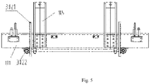
- a lift oil cylinder/air cylinder 301 is selected as a lift driving device 300, and each upright post 103 is fixedly provided with the lift oil cylinder/air cylinder 301, a cylinder rod of each lift oil cylinder/air cylinder is connected to the base 101 through a lift frame 105.
- a cylinder body of the lift oil cylinder/air cylinder 301 is fixedly arranged on the upright post, and two jacking oil cylinders/air cylinders are respectively fixedly arranged on a left side surface and a right side surface of the base 101 to serve as closing positioning and supporting devices, each jacking oil cylinder/air cylinder respectively includes a second jacking oil cylinder/air cylinder 201A and a third jacking oil cylinder/air cylinder 201B, a cylinder rod of the third jacking oil cylinder/air cylinder 201B is higher than a cylinder rod of the second jacking oil cylinder/air cylinder 201.
- Second jacking blocks 203A are arranged on side surfaces of a left side and a right side of a plate-shaped pressing member of a second lamination working layer, a third jacking block 203B is arranged on a third plate-shaped pressing member of a third lamination working layer, the second jacking block corresponds to the cylinder rod of the second jacking oil cylinder/air cylinder in position, and the third jacking block corresponds to the cylinder rod of the third jacking oil cylinder/air cylinder in position.
- the cylinder rod of the third jacking air cylinder jacks the third jacking block
- the cylinder rod of the second jacking air cylinder jacks the second jacking block.
- Three telescopic oil cylinders/air cylinders 202 are respectively arranged on a left side and a right side of the upper cover 102 as supporting devices for the top-layer plate-shaped pressing member and a device carried thereon, and a cylinder rod of the telescopic oil cylinder/air cylinder 202 is fixedly connected to the top-layer plate-shaped pressing member 401.
- the telescopic oil cylinder/air cylinder may also be replaced with the jacking oil cylinder/air cylinder.
- tensioning of the top-layer plate-shaped pressing member by the telescopic oil cylinder/air cylinder has the following advantages compared with supporting by using the jacking air cylinder. Since the upper cover is fixed, gravity of the top-layer plate-shaped pressing member and gravity of the device carried thereon are shared by the upper cover, which may reduce a load of the base.
- a synchronization device is arranged to make each layer of plate-shaped pressing member synchronously ascend and descend.
- the upper cover is provided with a vacuumizing pipeline and a vacuum interface, which are in communication with a vacuum device (not shown in the figure), and a vent hole 407 is provided at an edge position in the plate-shaped pressing member and located on the elastic sealing member, such that space formed between all the lamination working layers are in communication with one another.
- a vacuumizing pipeline and a vacuum interface which are in communication with a vacuum device (not shown in the figure)
- a vent hole 407 is provided at an edge position in the plate-shaped pressing member and located on the elastic sealing member, such that space formed between all the lamination working layers are in communication with one another.
- each plate-shaped pressing member and the device carried thereof such as a conveyor belt, a transmission shaft, a transmission shaft driving device and a tension air cylinder are collectively referred to as a lamination working layer.
- each layer of plate-shaped pressing member is supported by the cover opening support device, a distance between all layers of plate-shaped pressing members is H, a height of each layer of plate-shaped pressing member corresponds to that of a material table or lamination section butted front and back in actual production, materials of each layer are transported to the plate-shaped pressing member 401 of the corresponding layer by a conveyor belt 403 of each layer, the lift oil cylinder/air cylinder 3 moves to push the base 101 to ascend, so as to push a bottom lamination working layer 4001 to ascend, and the bottom-layer plate-shaped pressing member 4011 is attached to a sealing strip 106 of the base.
- the telescopic oil cylinder/air cylinder retracts to make the top-layer plate-shaped pressing member 401 to attach to the sealing strip 106 of the upper cover 102.
- the second jacking air cylinder 201A outputs thrust greater than gravity of the second lamination working layer 4002
- the third jacking air cylinder 201B outputs thrust greater than gravity of the third lamination working layer 4003.
- the cylinder rod of the third jacking oil cylinder/air cylinder 201B comes into contact with the third jacking block 203B and supports the third lamination working layer 4003. At this time, a distance between the lamination working layers is h, and a distance ⁇ h between the plate-shaped pressing members of the two adjacent lamination working layers is greater than a thickness of a conventional maximum thickness module. Moreover, the inflatable sealing ring of each layer may produce effective sealing, and the laminator enters the closed state.
- a thickness of a conventional module is no greater than 15 mm generally, which may change with changes of products.
- the plate-shaped pressing member of each layer ascends in place, and performs heating and curing on the module after ascending and descending in place.
- gas left between the modules is pumped out by a vacuumizing device, and then lamination is performed.
- the second jacking oil cylinder/air cylinder 201A outputs thrust equal to gravity of the second lamination working layer 4002
- the third jacking oil cylinder/air cylinder 201B outputs thrust equal to gravity of the third lamination working layer 4003.
- the telescopic oil cylinder/air cylinder exerts pulling force equal to gravity of the top lamination working layer 4003 to offset a pressure on the products caused by the gravity of each upper lamination working layer, the cylinder rod of the lift oil cylinder/air cylinder 3 continues to ascend, such that the module comes into contact with the upper and lower plate-shaped pressing members and a lamination pressure is produced.
- the output thrust of the lift oil cylinder/air cylinder 3 depends on a lamination process and is equal to a pressure required to be applied to the module. All the lift oil cylinders/air cylinders move synchronously through the synchronization device 302. As shown in Figs.
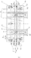
- a rack-and-pinion synchronization device in which two gear shafts are arranged side by side front and back, and are adapted to the oil cylinder in position.
- a front end and a rear end of the gear shaft 3023 are respectively connected to gears 3022, and each upright post is correspondingly provided with a rack 3021, the gear and the rack are in meshing transmission connection, the gear shaft is fixedly connected to the base, an intermediate transmission shaft 3025 is arranged between the two gear shafts 3023, and both ends of the intermediate transmission shaft are respectively in meshing transmission connection to the gear shaft on a corresponding side through bevel gears 3024.
- a hydraulic synchronization device may also be used, which is a common synchronization device used in the prior art and will not be described any more.
- a structure is basically the same as that of Embodiment 9 except a difference that a plate-shaped pressing member is a cooling plate provided with a cooling medium, a pipeline and an interface for vacuumizing may be arranged, the pipeline and the interface for vacuumizing may not be arranged when vacuumizing is not needed before lamination, in which cooling and pressure applying may be directly performed.
- a chamber of each lamination working layer may be independently vacuumized.
- a vacuumizing interface and pipeline is arranged on a plate-shaped pressing member of each lamination working layer, for example, the vacuumizing interface is arranged on a side wall of the plate-shaped pressing member, and the vacuumizing pipeline is also arranged on the side wall of the plate-shaped pressing member, and is in communication with the vacuumizing interface and an inner chamber of the chamber.
- a lamination pressure is finely adjusted based on size of force output by a supporting device.
- the number of pressing layers may be set according to different production scales, for example, two lamination working layers may be set, in this case, one working chamber may be formed to laminate a workpiece, or more layers of lamination working layers may be arranged. There is no limit to the number of working layers, which may provide as much production capacity as possible in limited space. Moreover, all layers may be closed and laminated at the same time, which may greatly improve the efficiency of lamination work and multiply productivity of one apparatus.
- both surfaces of the workpiece are heated or cooled at the same time, and are heated or cooled uniformly, through which uniform and rapid heating or cooling may be achieved, and the production efficiency may be also improved.
- an upper cover and a base serve as pressure applying parts
- an oil cylinder/air cylinder serves as a force output device
- the workpiece is pressed through pressure between the upper cover and base
- a pressure on the workpiece that is, a pressure on a surface of the workpiece is adjusted by adjusting an output pressure of the oil cylinder/air cylinder
- the lift oil cylinder/air cylinder is wide in range of the output pressure and convenient and rapid in pressure adjustment.
- the plate-shaped pressing member of each lamination working layer, the upper cover and the base are all plate-shaped structures, and the sealing strip 106 merely serves as a sealing member but not as a pressure-bearing member, and is located in the sealed groove during lamination.
- All the elastic sealing members are all inflatable sealing rings, and play a role in adapting to deformation under different pressures, which not only form seals between adjacent plate-shaped pressing members, but also adapt to different pressures, such that an output pressure of the oil cylinder/air cylinder is directly transmitted to the module, and pressure loss between the output pressure and pressure suffered by the workpiece is less.
- the plate-shaped pressing member between the upper cover and the base is pressed, and the plate-shaped pressing member transmits the pressure to the module. Since a shape of a surface of the plate-shaped pressing member matches a shape of a surface of a laminated workpiece, the surface of the plate-shaped pressing member is in full contact with the surface of the workpiece, such that the heat transmission effect is good, the pressure applying is uniform, and the workpiece is not prone to warp.
- the laminator of the present invention may be arranged at different stations of a lamination working line, and is preferably used as a first chamber of a lamination process for hot pressing and curing.
- the laminator may match and be combined with any kind of laminator on a production line.
- a flexible pad is arranged below the plate-shaped pressing member, such as a fabric and a rubber pad, with a general thickness of 1-10 mm.
- the closing positioning and supporting device and the lift driving device may also adopt the air cylinder, a lifting pulley, hoist, etc. It is better to use the inflatable sealing ring as the elastic sealing strip.
- the advantage of using the inflatable sealing ring is that different workpieces may be inflated with gas with different pressures, such that the pressure of plate-shaped pressing member is buffered.
- the method of the present invention is applicable to pressing of any workpiece with an interlamellar bonding layer, and is not limited to pressure applying on a solar cell module.
Landscapes
- Engineering & Computer Science (AREA)
- Mechanical Engineering (AREA)
- Physics & Mathematics (AREA)
- Fluid Mechanics (AREA)
- General Physics & Mathematics (AREA)
- Electromagnetism (AREA)
- Condensed Matter Physics & Semiconductors (AREA)
- Computer Hardware Design (AREA)
- Microelectronics & Electronic Packaging (AREA)
- Power Engineering (AREA)
- Manufacturing & Machinery (AREA)
- Quality & Reliability (AREA)
- Photovoltaic Devices (AREA)
- Lining Or Joining Of Plastics Or The Like (AREA)
Applications Claiming Priority (2)
| Application Number | Priority Date | Filing Date | Title |
|---|---|---|---|
| CN202011175993 | 2020-10-28 | ||
| CN202110172250.3A CN113002039B (zh) | 2020-10-28 | 2021-02-08 | 一种新型的板压式层压机及层压板状件的施压方法 |
Publications (1)
| Publication Number | Publication Date |
|---|---|
| EP3991971A1 true EP3991971A1 (en) | 2022-05-04 |
Family
ID=76383843
Family Applications (1)
| Application Number | Title | Priority Date | Filing Date |
|---|---|---|---|
| EP21171807.7A Pending EP3991971A1 (en) | 2020-10-28 | 2021-05-03 | Plate pressing type laminator and pressure applying method |
Country Status (2)
| Country | Link |
|---|---|
| EP (1) | EP3991971A1 (zh) |
| CN (1) | CN113002039B (zh) |
Families Citing this family (1)
| Publication number | Priority date | Publication date | Assignee | Title |
|---|---|---|---|---|
| CN114744068B (zh) * | 2022-03-30 | 2024-03-19 | 天津南玻节能玻璃有限公司 | 一种光伏建筑一体化组件及其制备方法 |
Citations (5)
| Publication number | Priority date | Publication date | Assignee | Title |
|---|---|---|---|---|
| EP1609597A2 (de) * | 2004-06-04 | 2005-12-28 | Meier Vakuumtechnik GmbH | Laminator zum Herstellen von Schichtkörpern |
| US20080295956A1 (en) * | 2007-05-30 | 2008-12-04 | Robert Burkle Gmbh | Method and device for laminating essentially plate-shaped workpieces under the effect of pressure and heat |
| US20090242137A1 (en) * | 2008-04-01 | 2009-10-01 | Nisshinbo Industries, Inc. | Stacked laminator |
| EP2145753A2 (de) | 2008-07-18 | 2010-01-20 | Robert Bürkle GmbH | Mehretagen-Laminierpresse |
| DE102009042148B4 (de) * | 2009-09-14 | 2019-10-10 | Schmid Technology Systems Gmbh | 14.09.2009Etagenpresse und Verfahren zur Herstellung von plattenförmigen Werkstücken |
Family Cites Families (6)
| Publication number | Priority date | Publication date | Assignee | Title |
|---|---|---|---|---|
| JP2001313407A (ja) * | 2000-04-27 | 2001-11-09 | Nisshinbo Ind Inc | ラミネート装置 |
| CN102886961B (zh) * | 2012-10-24 | 2015-04-22 | 秦皇岛丰泰自动化设备制造有限公司 | 一种电池组件层压机 |
| CN107215074A (zh) * | 2017-04-01 | 2017-09-29 | 秦皇岛可视自动化设备有限公司 | 一种新型的板状件层压机及层压板状件的方法 |
| CN108688287B (zh) * | 2018-05-09 | 2023-11-24 | 秦皇岛可视自动化设备有限公司 | 层压生产线、层压机、上盖、弹性密封圈、层压方法 |
| CN210489760U (zh) * | 2019-11-20 | 2020-05-08 | 速博达(深圳)自动化有限公司 | 电芯整形装置 |
| CN211194678U (zh) * | 2019-11-23 | 2020-08-07 | 山东吉成橡塑有限公司 | 一种pe发泡板的层压机 |
-
2021
- 2021-02-08 CN CN202110172250.3A patent/CN113002039B/zh active Active
- 2021-05-03 EP EP21171807.7A patent/EP3991971A1/en active Pending
Patent Citations (5)
| Publication number | Priority date | Publication date | Assignee | Title |
|---|---|---|---|---|
| EP1609597A2 (de) * | 2004-06-04 | 2005-12-28 | Meier Vakuumtechnik GmbH | Laminator zum Herstellen von Schichtkörpern |
| US20080295956A1 (en) * | 2007-05-30 | 2008-12-04 | Robert Burkle Gmbh | Method and device for laminating essentially plate-shaped workpieces under the effect of pressure and heat |
| US20090242137A1 (en) * | 2008-04-01 | 2009-10-01 | Nisshinbo Industries, Inc. | Stacked laminator |
| EP2145753A2 (de) | 2008-07-18 | 2010-01-20 | Robert Bürkle GmbH | Mehretagen-Laminierpresse |
| DE102009042148B4 (de) * | 2009-09-14 | 2019-10-10 | Schmid Technology Systems Gmbh | 14.09.2009Etagenpresse und Verfahren zur Herstellung von plattenförmigen Werkstücken |
Also Published As
| Publication number | Publication date |
|---|---|
| CN113002039A (zh) | 2021-06-22 |
| CN113002039B (zh) | 2023-07-25 |
Similar Documents
| Publication | Publication Date | Title |
|---|---|---|
| CN1311962C (zh) | 加热型真空压力加工装置 | |
| CN206856212U (zh) | 一种新型多层太阳电池组件层压机 | |
| CN110911516B (zh) | 一种柔性cigs太阳能电池片层叠串焊装置 | |
| EP3991971A1 (en) | Plate pressing type laminator and pressure applying method | |
| CN211467771U (zh) | 一种膜片真空贴合装置及由其组成的真空贴合设备 | |
| CN102005395B (zh) | 真空贴装方法及装置 | |
| CN110634997A (zh) | 光伏层压机及其使用方法 | |
| CN115101615A (zh) | 封闭式光伏组件层压机、层压设备及层压方法 | |
| CN109192820B (zh) | 多层多腔层压系统及其使用方法 | |
| CN111098581A (zh) | 一种异形玻璃夹胶设备 | |
| CN214544951U (zh) | 真空贴膜机 | |
| CN108688287B (zh) | 层压生产线、层压机、上盖、弹性密封圈、层压方法 | |
| CN216139620U (zh) | 板压式层压机 | |
| CN201808263U (zh) | 太阳电池组件固定式多层层压装置 | |
| CN102336044A (zh) | 太阳电池组件的层压方法 | |
| KR20130037640A (ko) | 진공 단열재 및 그 제조 방법 및 제조 장치 | |
| CN113829723B (zh) | 一种能够将多层基材一体成型的真空热压机 | |
| CN214239923U (zh) | 层压腔硬压机构及层压机层压总成 | |
| JP4773938B2 (ja) | 太陽電池モジュールのラミネート装置。 | |
| CN218004889U (zh) | 层压生产装置 | |
| ES2849651T3 (es) | Aparato de laminación y procedimiento para laminar al menos una pila de capas | |
| CN216183556U (zh) | 一种多层高效层压机 | |
| CN108724892B (zh) | 一种改进的层压装置 | |
| CN208835080U (zh) | 多层多腔层压系统 | |
| CN206781189U (zh) | 层压板状件的层压机 |
Legal Events
| Date | Code | Title | Description |
|---|---|---|---|
| PUAI | Public reference made under article 153(3) epc to a published international application that has entered the european phase |
Free format text: ORIGINAL CODE: 0009012 |
|
| STAA | Information on the status of an ep patent application or granted ep patent |
Free format text: STATUS: REQUEST FOR EXAMINATION WAS MADE |
|
| 17P | Request for examination filed |
Effective date: 20210503 |
|
| AK | Designated contracting states |
Kind code of ref document: A1 Designated state(s): AL AT BE BG CH CY CZ DE DK EE ES FI FR GB GR HR HU IE IS IT LI LT LU LV MC MK MT NL NO PL PT RO RS SE SI SK SM TR |
|
| TPAC | Observations filed by third parties |
Free format text: ORIGINAL CODE: EPIDOSNTIPA |
|
| STAA | Information on the status of an ep patent application or granted ep patent |
Free format text: STATUS: EXAMINATION IS IN PROGRESS |
|
| 17Q | First examination report despatched |
Effective date: 20230509 |
|
| GRAP | Despatch of communication of intention to grant a patent |
Free format text: ORIGINAL CODE: EPIDOSNIGR1 |
|
| STAA | Information on the status of an ep patent application or granted ep patent |
Free format text: STATUS: GRANT OF PATENT IS INTENDED |
|
| INTG | Intention to grant announced |
Effective date: 20240625 |