EP3991002B1 - Steuervorrichtung für ein fluidheizsystem - Google Patents
Steuervorrichtung für ein fluidheizsystem Download PDFInfo
- Publication number
- EP3991002B1 EP3991002B1 EP20747034.5A EP20747034A EP3991002B1 EP 3991002 B1 EP3991002 B1 EP 3991002B1 EP 20747034 A EP20747034 A EP 20747034A EP 3991002 B1 EP3991002 B1 EP 3991002B1
- Authority
- EP
- European Patent Office
- Prior art keywords
- temperature
- microcontroller
- electronic switch
- open
- control device
- Prior art date
- Legal status (The legal status is an assumption and is not a legal conclusion. Google has not performed a legal analysis and makes no representation as to the accuracy of the status listed.)
- Active
Links
Images
Classifications
-
- G—PHYSICS
- G05—CONTROLLING; REGULATING
- G05D—SYSTEMS FOR CONTROLLING OR REGULATING NON-ELECTRIC VARIABLES
- G05D23/00—Control of temperature
- G05D23/19—Control of temperature characterised by the use of electric means
- G05D23/1927—Control of temperature characterised by the use of electric means using a plurality of sensors
- G05D23/193—Control of temperature characterised by the use of electric means using a plurality of sensors sensing the temperaure in different places in thermal relationship with one or more spaces
- G05D23/1931—Control of temperature characterised by the use of electric means using a plurality of sensors sensing the temperaure in different places in thermal relationship with one or more spaces to control the temperature of one space
-
- G—PHYSICS
- G05—CONTROLLING; REGULATING
- G05D—SYSTEMS FOR CONTROLLING OR REGULATING NON-ELECTRIC VARIABLES
- G05D23/00—Control of temperature
- G05D23/19—Control of temperature characterised by the use of electric means
- G05D23/20—Control of temperature characterised by the use of electric means with sensing elements having variation of electric or magnetic properties with change of temperature
- G05D23/24—Control of temperature characterised by the use of electric means with sensing elements having variation of electric or magnetic properties with change of temperature the sensing element having a resistance varying with temperature, e.g. a thermistor
-
- H—ELECTRICITY
- H05—ELECTRIC TECHNIQUES NOT OTHERWISE PROVIDED FOR
- H05B—ELECTRIC HEATING; ELECTRIC LIGHT SOURCES NOT OTHERWISE PROVIDED FOR; CIRCUIT ARRANGEMENTS FOR ELECTRIC LIGHT SOURCES, IN GENERAL
- H05B1/00—Details of electric heating devices
- H05B1/02—Automatic switching arrangements specially adapted to apparatus ; Control of heating devices
- H05B1/0227—Applications
- H05B1/023—Industrial applications
- H05B1/0236—Industrial applications for vehicles
-
- H—ELECTRICITY
- H05—ELECTRIC TECHNIQUES NOT OTHERWISE PROVIDED FOR
- H05B—ELECTRIC HEATING; ELECTRIC LIGHT SOURCES NOT OTHERWISE PROVIDED FOR; CIRCUIT ARRANGEMENTS FOR ELECTRIC LIGHT SOURCES, IN GENERAL
- H05B1/00—Details of electric heating devices
- H05B1/02—Automatic switching arrangements specially adapted to apparatus ; Control of heating devices
- H05B1/0227—Applications
- H05B1/023—Industrial applications
- H05B1/0244—Heating of fluids
Definitions
- the invention relates to a control device for a fluid heating system, preferably liquid, for a motor vehicle, in particular an electric or hybrid vehicle.
- such a system for heating a fluid preferably liquid, comprises an electric heating element and a chamber shaped so that the fluid is heated by said electric element in the chamber.
- the control device of the electric heating element generally includes at least one power transistor, supplied by a high voltage and whose gate is driven by a circuit supplied by a low voltage.
- the high voltage is for example of the order of 350 V while the low voltage is of the order of 12 V.
- the heater may operate continuously, which creates a fire risk when the water boils and evaporates, which is not acceptable, particularly in view of the ISO 26262 standard.
- the aim of the present invention is to remedy this drawback.
- GB2479088A And DE102013102465A1 disclose fluid heating device control systems.
- a device for controlling a system for heating a fluid preferably a liquid fluid, for a motor vehicle, comprising at least one electrical heating element configured to heat said fluid
- the control device comprising a first electronic switch capable of being connected to the electrical heating element and a second electronic switch capable of being connected to the electrical heating element, a sensor of measurement of a first temperature and a microcontroller associated with the first electronic switch, the microcontroller being configured to open or close the first switch according to the value of the first measured temperature, a sensor for measuring a second temperature and a logic control module associated with the second electronic switch and comprising a comparator arranged to compare the second measured temperature to a threshold, the module being configured to open or close the second switch according to the result of the comparison.
- the module is configured to open the second electronic switch if the second temperature is greater than a threshold.
- the module comprises a digital coupling link between the microcontroller and the logic control module, configured to communicate the second measured temperature to the microcontroller and/or to activate or deactivate the second electronic switch.
- the microcontroller is configured to open the first electronic switch if an absolute value of a difference between the values of the first and second measured temperatures is greater than a threshold.
- the logic control module comprises another comparator for comparing the first temperature to a threshold value, and being configured to open the second electronic switch if the first temperature is greater than a threshold.
- the logic control module comprises a first and second temperature consistency means configured to open the second electronic switch if the first temperature is different from the second temperature.
- the device comprises a switching power supply.
- a system for heating a fluid, in particular liquid comprising an electric heating element and a control device as described previously.
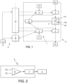
- control device 1 for a system for heating a fluid 100, preferably a liquid fluid, for a motor vehicle.
- the heating system 100 comprises an electric heating element, 101.
- the heating element 101 is advantageously a cylindrical heating tube comprising a heating resistor R of the screen-printed track type, of the shielded resistance type or of the positive temperature coefficient type.
- the heating system 100 also comprises a chamber 102 in which the liquid fluid F, for example glycolated water, circulates and in which the heating element 101 is immersed, so that the fluid F is heated by the electric heating element 101 in the chamber 102.
- the liquid fluid F for example glycolated water
- the first embodiment is described in relation to the Figures 1 and 2 .
- control device 1 comprises a first electronic switch 2 and a second electronic switch 3.
- the first and second switches 2, 3 are insulated gate bipolar power transistors, known as IGBTs (for Insulated Gate Bipolar Transistor, in English).
- IGBTs Insulated Gate Bipolar Transistor
- the control device 1 also comprises a microcontroller 4 associated with the first switch 2 and configured to open or close the first switch 2.
- microcontroller 4 applies a so-called low voltage, in particular of the order of 12V, to the gate of transistor 2 to close transistor 2 and a zero voltage to open transistor 2.
- the control device 1 also comprises a temperature sensor, for example of the PTC or NTC type, for measuring a first temperature T1.
- the temperature T1 is measured in the chamber 102 or in the vicinity thereof in order to directly or indirectly determine the temperature of the fluid circulating in the heating system 100.
- Microcontroller 4 is configured to open transistor 2 when T1 is greater than a threshold value.
- control device 1 comprises a module 5 for logic control of the second switch 3.
- the logic control module 5 differs from a microcontroller in that it includes fewer signal processing steps. In particular, the module does not include an analog-to-digital converter. In addition, there is a direct connection from the current source to the comparator(s) with which it is equipped, as will be detailed.
- the logic control module only has the function for which it is designed, unlike the microcontroller which works according to its programming (with the “software”, in English).
- the logic control module 5 allows, unlike the prior art, to provide safety redundancy by dispensing with a second microcontroller. Thus, certain signal processing steps are eliminated, which gives the control device greater robustness.
- the module 5 comprises a comparator 6 arranged to compare a second measured temperature T2 with a threshold, and a means 7 for controlling the gate of the transistor 3 connected to the comparator 5 and configured to open or close the second switch 3 depending on the result of the comparison.
- the gate control means 7 is configured to open the transistor 3 when T2 is greater than a threshold value.
- the transistors 2, 3 are connected in series to the electric heating element 101 between two potentials denoted HV+ and HV- (for High Voltage), forming a so-called high voltage circuit 8.
- HV+ and HV- for High Voltage
- the HV+ voltage is for example of the order of 350V.
- the control device 1 comprises a low voltage circuit 9 comprising a switching power supply of the so-called “flyback” type comprising in a known manner a transformer 12 connected to an electrical source 11, and making it possible to electrically power the microcontroller 4, the module 5, and the transistors 2 and 3.
- the electrical source is said to be low voltage, and provides a voltage between 5V and 20V, for example 12V or 15V.
- control device 1 also comprises a digital coupler 13 between the microcontroller 4 and the module 5.
- the temperature T1 and/or the temperature T2 becomes higher than the threshold value and the first transistor 2 and/or the second transistor 3 opens, thanks respectively to the microcontroller 4 and the module 5, which avoids any risk of fire.
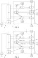
- the second embodiment is described in relation to the Figure 3 .
- the control device 1 comprises an analog-digital converter 14 for transmitting the temperature T2 to the microcontroller 4 via the digital coupler 13.
- the physical bus can be an I2C (for Inter-Integrated Circuit, in English) or SPI (for Serial Peripheral Interface, in English).
- the microcontroller 4 can be configured to check the consistency of the temperatures T1 and T2 and to open the first transistor 2 if T1 and T2 are not consistent (their difference being greater, in absolute value, than a threshold, which can be chosen to be zero).
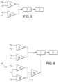
- the third embodiment is described in relation to the figures 4 to 6 .
- a PMW modulated duty cycle signal (for pulse width modulation, in English, or PWM, in French), depending on the temperature T1, is transmitted from the microcontroller 4 to the module 5 via the coupler 13.
- the module 5 comprises, in addition to the comparator 6, a comparator 15 arranged to compare the first temperature T1, using the PWM signal.
- the comparator 15 is connected to the control means 7 of the gate of the transistor 3, so that the second transistor 3 is open if T1 is greater than the threshold or if T2 is greater than the threshold.
- the module 5 comprises, in addition to the comparators 6 and 15, a means 16 for comparing the temperatures T1 and T2, connected to the control means 7 of the gate of the transistor 3, so that the second transistor 3 is open if the temperatures T1 and T2 differ by a threshold, which can be chosen to be zero.
- the means 16 comprises a first subtractor 17, a second subtractor 18 and a comparator 19.
- the first subtractor 17 has the signal T1 as its positive input and the signal T2 as its negative input, while the second subtractor has the signal T2 as its positive input and the signal T1 as its negative input, which makes it possible to compare in the comparator 19 the difference between the two temperatures with the threshold value ⁇ .
- the device 1 advantageously comprises, as illustrated in the figures 1 , 3 and 4 , a digital coupler 20, powered by the source 11 and arranged between the low voltage circuit 9 and the microcontroller 4, in order to communicate other information for the operation of the control device 1.
Landscapes
- Engineering & Computer Science (AREA)
- Physics & Mathematics (AREA)
- General Physics & Mathematics (AREA)
- Automation & Control Theory (AREA)
- Remote Sensing (AREA)
- Control Of Temperature (AREA)
- Air-Conditioning For Vehicles (AREA)
- Control Of Resistance Heating (AREA)
Claims (8)
- Vorrichtung zur Steuerung eines Systems zum Erhitzen eines Fluids(F), bevorzugt eines flüssigen Fluids, für ein Kraftfahrzeug, umfassend mindestens ein elektrisches Heizelement (101), das dazu ausgestaltet ist, das Fluid (F) zu erhitzen, wobei die Vorrichtung zur Steuerung (1) umfasst:- einen ersten elektronischen Schalter (2), der geeignet ist, an das elektrische Heizelement (101) angeschlossen zu werden, und einen zweiten elektronischen Schalter (3), der geeignet ist, an das elektrische Heizelement (101) angeschlossen zu werden, wobei die ersten und zweiten Schalter (2, 3) in Reihe mit dem elektrischen Heizelement (101) verbunden sind,- einen Sensor zum Messen einer ersten Temperatur (T1) und einen Mikrocontroller (4), die dem ersten elektronischen Schalter (2) zugeordnet sind, wobei der Mikrocontroller (4) dazu ausgestaltet ist, den ersten Schalter (2) entsprechend dem Wert der ersten Temperatur (T1) zu öffnen oder zu schließen,- einen Sensor zum Messen einer zweiten Temperatur (T2) und ein Kontroll-Logikmodul (5), die dem zweiten elektronischen Schalter (3) zugeordnet sind und einen Komparator (6) umfassen, der dazu ausgebildet ist, die zweite gemessene Temperatur (T2) mit einem Schwellenwert zu vergleichen, wobei das Modul (5) dazu ausgestaltet ist, den zweiten Schalter (3) entsprechend dem Ergebnis des Vergleichs zu öffnen oder zu schließen,wobei die Vorrichtung zur Steuerung (1) auch einen digitalen Koppler (13) zwischen dem Mikrocontroller (4) und dem Kontroll-Logikmodul (5) umfasst, wobei der digitale Koppler (13) die Kommunikation zwischen dem Mikrocontroller (4) und dem Kontroll-Logikmodul (5) gewährleistet, wobei die Vorrichtung zur Steuerung dadurch gekennzeichnet ist, dass der Mikrocontroller (4) dazu ausgestaltet ist, die Aktivierung des zweiten Schalters (3) über das Kontroll-Logikmodul (5) anzusteuern.
- Vorrichtung nach dem vorhergehenden Anspruch, wobei das Modul (5) dazu ausgestaltet ist, den zweiten elektronischen Schalter (3) zu öffnen, wenn die zweite Temperatur (T2) über einem Schwellenwert liegt.
- Vorrichtung nach einem der vorstehenden Ansprüche, wobei der digitale Koppler (13) so konfiguriert ist, dass er die zweite gemessene Temperatur (T2) an den Mikrocontroller (4) übermittelt.
- Vorrichtung nach dem vorhergehenden Anspruch, wobei der Mikrocontroller (4) dazu ausgestaltet ist, den ersten elektronischen Schalter (2) zu öffnen, wenn ein absoluter Wert einer Differenz zwischen den Werten der ersten und zweiten gemessenen Temperaturen über einem Schwellenwert liegt.
- Vorrichtung nach einem der vorhergehenden Ansprüche, wobei das Kontroll-Logikmodul (5) einen weiteren Komparator (15) umfasst, um die erste Temperatur (T1) mit einem Schwellenwert zu vergleichen, und dazu ausgestaltet ist, den zweiten elektronischen Schalter (3) zu öffnen, wenn die erste Temperatur (T1) über einem Schwellenwert liegt.
- Vorrichtung nach dem vorhergehenden Anspruch, wobei das Kontroll-Logikmodul (5) ein Kohärenzmittel (16) für die ersten und zweiten Temperaturen (T1, T2) umfasst, das dazu ausgestaltet ist, den zweiten elektronischen Schalter (3) zu öffnen, wenn die erste Temperatur von der zweiten Temperatur verschieden ist.
- Vorrichtung nach einem der vorhergehenden Ansprüche, umfassend ein Schaltnetzteil (12).
- System zum Erhitzen eines, insbesondere flüssigen, Fluids, umfassend ein elektrisches Heizelement (101) und eine Vorrichtung zur Steuerung nach einem der vorhergehenden Ansprüche.
Applications Claiming Priority (2)
| Application Number | Priority Date | Filing Date | Title |
|---|---|---|---|
| FR1907080A FR3097983A1 (fr) | 2019-06-28 | 2019-06-28 | Dispositif de commande pour un système de chauffage d’un fluide |
| PCT/FR2020/051101 WO2020260824A1 (fr) | 2019-06-28 | 2020-06-24 | Dispositif de commande pour un systeme de chauffage d'un fluide |
Publications (2)
| Publication Number | Publication Date |
|---|---|
| EP3991002A1 EP3991002A1 (de) | 2022-05-04 |
| EP3991002B1 true EP3991002B1 (de) | 2025-07-02 |
Family
ID=68138466
Family Applications (1)
| Application Number | Title | Priority Date | Filing Date |
|---|---|---|---|
| EP20747034.5A Active EP3991002B1 (de) | 2019-06-28 | 2020-06-24 | Steuervorrichtung für ein fluidheizsystem |
Country Status (6)
| Country | Link |
|---|---|
| US (1) | US20220365547A1 (de) |
| EP (1) | EP3991002B1 (de) |
| JP (1) | JP7362785B2 (de) |
| CN (1) | CN114096932A (de) |
| FR (1) | FR3097983A1 (de) |
| WO (1) | WO2020260824A1 (de) |
Family Cites Families (11)
| Publication number | Priority date | Publication date | Assignee | Title |
|---|---|---|---|---|
| JPH07114287A (ja) * | 1993-10-15 | 1995-05-02 | Fujitsu Ltd | 熱定着機の制御方法及び同制御装置 |
| US5437002A (en) * | 1993-12-15 | 1995-07-25 | Paragon Electric Company, Inc. | Water heater control circuit including an empty tank sensor |
| US7932480B2 (en) * | 2006-04-05 | 2011-04-26 | Mks Instruments, Inc. | Multiple heater control system with expandable modular functionality |
| GB2479088B (en) * | 2006-04-05 | 2011-12-28 | Mks Instr Inc | Multiple heater control system with expandable modular functionality |
| JP2013220708A (ja) | 2012-04-16 | 2013-10-28 | Mitsubishi Heavy Ind Ltd | 熱媒体加熱装置およびそれを備えた車両用空調装置 |
| DE102013102465A1 (de) * | 2013-03-12 | 2014-09-18 | Refusol Gmbh | Heizvorrichtung |
| FR3007229B1 (fr) * | 2013-06-17 | 2015-06-19 | Valeo Systemes Thermiques | Commande d'un circuit de chauffage electrique, notamment pour vehicule automobile |
| CN104750140B (zh) * | 2013-12-31 | 2017-09-01 | 北京北方微电子基地设备工艺研究中心有限责任公司 | 反应腔加热控制方法及装置 |
| JP2015207502A (ja) | 2014-04-22 | 2015-11-19 | カルソニックカンセイ株式会社 | 車両用液体加熱装置 |
| FR3039334B1 (fr) * | 2015-07-22 | 2019-07-05 | Valeo Systemes Thermiques | Procede de securisation du fonctionnement d’un dispositif chauffant |
| JP2019075332A (ja) * | 2017-10-18 | 2019-05-16 | カルソニックカンセイ株式会社 | 加熱装置及び加熱装置の電力上限決定方法 |
-
2019
- 2019-06-28 FR FR1907080A patent/FR3097983A1/fr not_active Withdrawn
-
2020
- 2020-06-24 EP EP20747034.5A patent/EP3991002B1/de active Active
- 2020-06-24 US US17/623,347 patent/US20220365547A1/en not_active Abandoned
- 2020-06-24 CN CN202080046050.7A patent/CN114096932A/zh active Pending
- 2020-06-24 JP JP2021572494A patent/JP7362785B2/ja active Active
- 2020-06-24 WO PCT/FR2020/051101 patent/WO2020260824A1/fr not_active Ceased
Also Published As
| Publication number | Publication date |
|---|---|
| JP7362785B2 (ja) | 2023-10-17 |
| JP2022535904A (ja) | 2022-08-10 |
| US20220365547A1 (en) | 2022-11-17 |
| EP3991002A1 (de) | 2022-05-04 |
| WO2020260824A1 (fr) | 2020-12-30 |
| CN114096932A (zh) | 2022-02-25 |
| FR3097983A1 (fr) | 2021-01-01 |
Similar Documents
| Publication | Publication Date | Title |
|---|---|---|
| US4277672A (en) | Control circuit for controlling quantity of heat to electrically heatable windshield | |
| EP3577395B1 (de) | Elektrische heizvorrichtung, heizkreis und verfahren zur steureung der entsprechenden temperaturen | |
| FR3007229A1 (fr) | Commande d'un circuit de chauffage electrique, notamment pour vehicule automobile | |
| FR3013004A1 (fr) | Commande securisee d'un rechauffeur electrique | |
| EP0782265B1 (de) | Verfahren und Vorrichtung zum Schutz eines einstellbaren Impedanzelements zur Steuerung der Stromversorgung eines Elektromotors, insbesondere eines Kraftfahrzeugs | |
| FR2890168A1 (fr) | Dispositif de commande de capteur de temperature. | |
| JP4894847B2 (ja) | ヒータ劣化検出装置およびグロープラグ通電制御装置 | |
| JPH10255955A (ja) | 座席暖房の加熱電流の温度に依存した調整回路 | |
| EP3991002B1 (de) | Steuervorrichtung für ein fluidheizsystem | |
| WO2015052137A1 (fr) | Dispositif electrique ou electronique a deux tensions d'alimentation | |
| EP3087647B1 (de) | Leistungsregler mit linearer steuerung von stromspitzenbegrenzung und mit kurzschlussschutz | |
| EP3877772B1 (de) | Verfahren zur erkennung einer überhitzung einer heizvorrichtung und entsprechende steuereinheit | |
| EP3271993B1 (de) | Vorrichtung zur steuerung der stromversorgung einer schaltung für ein fahrzeug mit einer batterie und entsprechende anordnung | |
| FR3097946A1 (fr) | Système de chauffage d’un fluide | |
| EP2725876A1 (de) | Elektrische Anschlussvorrichtung eines Scheinwerfers | |
| KR20230064237A (ko) | 렌즈 이물 감지 히터 및 카메라 장치 | |
| FR3088120A1 (fr) | Procede de detection de surchauffe pour dispositif de chauffage et unite de commande correspondante | |
| WO1999048183A1 (fr) | Bloc de moteur electrique, notamment pour vehicule automobile, integrant une electronique de commande | |
| FR3053206A1 (fr) | Circuit de protection, ensemble d'eclairage et son procede de fonctionnement | |
| EP4002212B1 (de) | Mikroschaltkreis-karte | |
| FR3039903B1 (fr) | Systeme d'acces et de demarrage mains libres d'un vehicule automobile | |
| FR3094849A1 (fr) | Alimentation électrique d’éclairage de caméra | |
| FR2848741A1 (fr) | Systeme de controle de l'alimentation en energie d'un ventilateur de refroidissement d'un composant electrique de vehicule automobile | |
| EP3201576B1 (de) | Luftstromerkennungsvorrichtung | |
| FR2772977A1 (fr) | Circuit electronique de commande d'un relais de puissance, notamment pour la commande de l'alimentation d'un element chauffant de pare-brise ou de lunette arriere de vehicule automobile |
Legal Events
| Date | Code | Title | Description |
|---|---|---|---|
| STAA | Information on the status of an ep patent application or granted ep patent |
Free format text: STATUS: UNKNOWN |
|
| STAA | Information on the status of an ep patent application or granted ep patent |
Free format text: STATUS: THE INTERNATIONAL PUBLICATION HAS BEEN MADE |
|
| PUAI | Public reference made under article 153(3) epc to a published international application that has entered the european phase |
Free format text: ORIGINAL CODE: 0009012 |
|
| STAA | Information on the status of an ep patent application or granted ep patent |
Free format text: STATUS: REQUEST FOR EXAMINATION WAS MADE |
|
| 17P | Request for examination filed |
Effective date: 20220124 |
|
| AK | Designated contracting states |
Kind code of ref document: A1 Designated state(s): AL AT BE BG CH CY CZ DE DK EE ES FI FR GB GR HR HU IE IS IT LI LT LU LV MC MK MT NL NO PL PT RO RS SE SI SK SM TR |
|
| DAV | Request for validation of the european patent (deleted) | ||
| DAX | Request for extension of the european patent (deleted) | ||
| P01 | Opt-out of the competence of the unified patent court (upc) registered |
Effective date: 20230528 |
|
| STAA | Information on the status of an ep patent application or granted ep patent |
Free format text: STATUS: EXAMINATION IS IN PROGRESS |
|
| 17Q | First examination report despatched |
Effective date: 20230809 |
|
| GRAP | Despatch of communication of intention to grant a patent |
Free format text: ORIGINAL CODE: EPIDOSNIGR1 |
|
| STAA | Information on the status of an ep patent application or granted ep patent |
Free format text: STATUS: GRANT OF PATENT IS INTENDED |
|
| INTG | Intention to grant announced |
Effective date: 20241028 |
|
| GRAJ | Information related to disapproval of communication of intention to grant by the applicant or resumption of examination proceedings by the epo deleted |
Free format text: ORIGINAL CODE: EPIDOSDIGR1 |
|
| STAA | Information on the status of an ep patent application or granted ep patent |
Free format text: STATUS: EXAMINATION IS IN PROGRESS |
|
| INTC | Intention to grant announced (deleted) | ||
| GRAP | Despatch of communication of intention to grant a patent |
Free format text: ORIGINAL CODE: EPIDOSNIGR1 |
|
| STAA | Information on the status of an ep patent application or granted ep patent |
Free format text: STATUS: GRANT OF PATENT IS INTENDED |
|
| INTG | Intention to grant announced |
Effective date: 20250217 |
|
| GRAS | Grant fee paid |
Free format text: ORIGINAL CODE: EPIDOSNIGR3 |
|
| GRAA | (expected) grant |
Free format text: ORIGINAL CODE: 0009210 |
|
| STAA | Information on the status of an ep patent application or granted ep patent |
Free format text: STATUS: THE PATENT HAS BEEN GRANTED |
|
| AK | Designated contracting states |
Kind code of ref document: B1 Designated state(s): AL AT BE BG CH CY CZ DE DK EE ES FI FR GB GR HR HU IE IS IT LI LT LU LV MC MK MT NL NO PL PT RO RS SE SI SK SM TR |
|
| REG | Reference to a national code |
Ref country code: GB Ref legal event code: FG4D Free format text: NOT ENGLISH |
|
| REG | Reference to a national code |
Ref country code: CH Ref legal event code: EP |
|
| REG | Reference to a national code |
Ref country code: DE Ref legal event code: R096 Ref document number: 602020053817 Country of ref document: DE |
|
| REG | Reference to a national code |
Ref country code: IE Ref legal event code: FG4D Free format text: LANGUAGE OF EP DOCUMENT: FRENCH |
|
| REG | Reference to a national code |
Ref country code: NL Ref legal event code: MP Effective date: 20250702 |
|
| PG25 | Lapsed in a contracting state [announced via postgrant information from national office to epo] |
Ref country code: PT Free format text: LAPSE BECAUSE OF FAILURE TO SUBMIT A TRANSLATION OF THE DESCRIPTION OR TO PAY THE FEE WITHIN THE PRESCRIBED TIME-LIMIT Effective date: 20251103 |
|
| PG25 | Lapsed in a contracting state [announced via postgrant information from national office to epo] |
Ref country code: NL Free format text: LAPSE BECAUSE OF FAILURE TO SUBMIT A TRANSLATION OF THE DESCRIPTION OR TO PAY THE FEE WITHIN THE PRESCRIBED TIME-LIMIT Effective date: 20250702 |
|
| REG | Reference to a national code |
Ref country code: AT Ref legal event code: MK05 Ref document number: 1809937 Country of ref document: AT Kind code of ref document: T Effective date: 20250702 |
|
| PG25 | Lapsed in a contracting state [announced via postgrant information from national office to epo] |
Ref country code: IS Free format text: LAPSE BECAUSE OF FAILURE TO SUBMIT A TRANSLATION OF THE DESCRIPTION OR TO PAY THE FEE WITHIN THE PRESCRIBED TIME-LIMIT Effective date: 20251102 |
|
| PG25 | Lapsed in a contracting state [announced via postgrant information from national office to epo] |
Ref country code: NO Free format text: LAPSE BECAUSE OF FAILURE TO SUBMIT A TRANSLATION OF THE DESCRIPTION OR TO PAY THE FEE WITHIN THE PRESCRIBED TIME-LIMIT Effective date: 20251002 |
|
| REG | Reference to a national code |
Ref country code: LT Ref legal event code: MG9D |
|
| PG25 | Lapsed in a contracting state [announced via postgrant information from national office to epo] |
Ref country code: AT Free format text: LAPSE BECAUSE OF FAILURE TO SUBMIT A TRANSLATION OF THE DESCRIPTION OR TO PAY THE FEE WITHIN THE PRESCRIBED TIME-LIMIT Effective date: 20250702 |
|
| PG25 | Lapsed in a contracting state [announced via postgrant information from national office to epo] |
Ref country code: FI Free format text: LAPSE BECAUSE OF FAILURE TO SUBMIT A TRANSLATION OF THE DESCRIPTION OR TO PAY THE FEE WITHIN THE PRESCRIBED TIME-LIMIT Effective date: 20250702 |
|
| PG25 | Lapsed in a contracting state [announced via postgrant information from national office to epo] |
Ref country code: HR Free format text: LAPSE BECAUSE OF FAILURE TO SUBMIT A TRANSLATION OF THE DESCRIPTION OR TO PAY THE FEE WITHIN THE PRESCRIBED TIME-LIMIT Effective date: 20250702 |
|
| PG25 | Lapsed in a contracting state [announced via postgrant information from national office to epo] |
Ref country code: GR Free format text: LAPSE BECAUSE OF FAILURE TO SUBMIT A TRANSLATION OF THE DESCRIPTION OR TO PAY THE FEE WITHIN THE PRESCRIBED TIME-LIMIT Effective date: 20251003 |
|
| PG25 | Lapsed in a contracting state [announced via postgrant information from national office to epo] |
Ref country code: CZ Free format text: LAPSE BECAUSE OF FAILURE TO SUBMIT A TRANSLATION OF THE DESCRIPTION OR TO PAY THE FEE WITHIN THE PRESCRIBED TIME-LIMIT Effective date: 20250702 Ref country code: SE Free format text: LAPSE BECAUSE OF FAILURE TO SUBMIT A TRANSLATION OF THE DESCRIPTION OR TO PAY THE FEE WITHIN THE PRESCRIBED TIME-LIMIT Effective date: 20250702 |
|
| PG25 | Lapsed in a contracting state [announced via postgrant information from national office to epo] |
Ref country code: LV Free format text: LAPSE BECAUSE OF FAILURE TO SUBMIT A TRANSLATION OF THE DESCRIPTION OR TO PAY THE FEE WITHIN THE PRESCRIBED TIME-LIMIT Effective date: 20250702 |
|
| PG25 | Lapsed in a contracting state [announced via postgrant information from national office to epo] |
Ref country code: BG Free format text: LAPSE BECAUSE OF FAILURE TO SUBMIT A TRANSLATION OF THE DESCRIPTION OR TO PAY THE FEE WITHIN THE PRESCRIBED TIME-LIMIT Effective date: 20250702 Ref country code: PL Free format text: LAPSE BECAUSE OF FAILURE TO SUBMIT A TRANSLATION OF THE DESCRIPTION OR TO PAY THE FEE WITHIN THE PRESCRIBED TIME-LIMIT Effective date: 20250702 |
|
| PG25 | Lapsed in a contracting state [announced via postgrant information from national office to epo] |
Ref country code: RS Free format text: LAPSE BECAUSE OF FAILURE TO SUBMIT A TRANSLATION OF THE DESCRIPTION OR TO PAY THE FEE WITHIN THE PRESCRIBED TIME-LIMIT Effective date: 20251002 |
|
| PG25 | Lapsed in a contracting state [announced via postgrant information from national office to epo] |
Ref country code: ES Free format text: LAPSE BECAUSE OF FAILURE TO SUBMIT A TRANSLATION OF THE DESCRIPTION OR TO PAY THE FEE WITHIN THE PRESCRIBED TIME-LIMIT Effective date: 20250702 |
|
| REG | Reference to a national code |
Ref country code: CH Ref legal event code: W10 Free format text: ST27 STATUS EVENT CODE: U-0-0-W10-W00 (AS PROVIDED BY THE NATIONAL OFFICE) Effective date: 20260218 |
|
| RAP2 | Party data changed (patent owner data changed or rights of a patent transferred) |
Owner name: VALEO ELECTRIFICATION |
|
| PG25 | Lapsed in a contracting state [announced via postgrant information from national office to epo] |
Ref country code: SM Free format text: LAPSE BECAUSE OF FAILURE TO SUBMIT A TRANSLATION OF THE DESCRIPTION OR TO PAY THE FEE WITHIN THE PRESCRIBED TIME-LIMIT Effective date: 20250702 |
|
| PG25 | Lapsed in a contracting state [announced via postgrant information from national office to epo] |
Ref country code: DK Free format text: LAPSE BECAUSE OF FAILURE TO SUBMIT A TRANSLATION OF THE DESCRIPTION OR TO PAY THE FEE WITHIN THE PRESCRIBED TIME-LIMIT Effective date: 20250702 |
|
| PG25 | Lapsed in a contracting state [announced via postgrant information from national office to epo] |
Ref country code: IT Free format text: LAPSE BECAUSE OF FAILURE TO SUBMIT A TRANSLATION OF THE DESCRIPTION OR TO PAY THE FEE WITHIN THE PRESCRIBED TIME-LIMIT Effective date: 20250702 |