EP3877772B1 - Verfahren zur erkennung einer überhitzung einer heizvorrichtung und entsprechende steuereinheit - Google Patents
Verfahren zur erkennung einer überhitzung einer heizvorrichtung und entsprechende steuereinheit Download PDFInfo
- Publication number
- EP3877772B1 EP3877772B1 EP19818214.9A EP19818214A EP3877772B1 EP 3877772 B1 EP3877772 B1 EP 3877772B1 EP 19818214 A EP19818214 A EP 19818214A EP 3877772 B1 EP3877772 B1 EP 3877772B1
- Authority
- EP
- European Patent Office
- Prior art keywords
- sub
- resistive elements
- pwm
- target
- subsystem
- Prior art date
- Legal status (The legal status is an assumption and is not a legal conclusion. Google has not performed a legal analysis and makes no representation as to the accuracy of the status listed.)
- Active
Links
Images
Classifications
-
- H—ELECTRICITY
- H05—ELECTRIC TECHNIQUES NOT OTHERWISE PROVIDED FOR
- H05B—ELECTRIC HEATING; ELECTRIC LIGHT SOURCES NOT OTHERWISE PROVIDED FOR; CIRCUIT ARRANGEMENTS FOR ELECTRIC LIGHT SOURCES, IN GENERAL
- H05B1/00—Details of electric heating devices
- H05B1/02—Automatic switching arrangements specially adapted to apparatus ; Control of heating devices
- H05B1/0227—Applications
-
- G—PHYSICS
- G05—CONTROLLING; REGULATING
- G05D—SYSTEMS FOR CONTROLLING OR REGULATING NON-ELECTRIC VARIABLES
- G05D23/00—Control of temperature
- G05D23/19—Control of temperature characterised by the use of electric means
- G05D23/1917—Control of temperature characterised by the use of electric means using digital means
-
- H—ELECTRICITY
- H05—ELECTRIC TECHNIQUES NOT OTHERWISE PROVIDED FOR
- H05B—ELECTRIC HEATING; ELECTRIC LIGHT SOURCES NOT OTHERWISE PROVIDED FOR; CIRCUIT ARRANGEMENTS FOR ELECTRIC LIGHT SOURCES, IN GENERAL
- H05B3/00—Ohmic-resistance heating
- H05B3/0019—Circuit arrangements
- H05B3/0023—Circuit arrangements for heating by passing the current directly across the material to be heated
-
- H—ELECTRICITY
- H05—ELECTRIC TECHNIQUES NOT OTHERWISE PROVIDED FOR
- H05B—ELECTRIC HEATING; ELECTRIC LIGHT SOURCES NOT OTHERWISE PROVIDED FOR; CIRCUIT ARRANGEMENTS FOR ELECTRIC LIGHT SOURCES, IN GENERAL
- H05B1/00—Details of electric heating devices
- H05B1/02—Automatic switching arrangements specially adapted to apparatus ; Control of heating devices
- H05B1/0227—Applications
- H05B1/023—Industrial applications
- H05B1/0236—Industrial applications for vehicles
-
- H—ELECTRICITY
- H05—ELECTRIC TECHNIQUES NOT OTHERWISE PROVIDED FOR
- H05B—ELECTRIC HEATING; ELECTRIC LIGHT SOURCES NOT OTHERWISE PROVIDED FOR; CIRCUIT ARRANGEMENTS FOR ELECTRIC LIGHT SOURCES, IN GENERAL
- H05B2203/00—Aspects relating to Ohmic resistive heating covered by group H05B3/00
- H05B2203/019—Heaters using heating elements having a negative temperature coefficient
-
- H—ELECTRICITY
- H05—ELECTRIC TECHNIQUES NOT OTHERWISE PROVIDED FOR
- H05B—ELECTRIC HEATING; ELECTRIC LIGHT SOURCES NOT OTHERWISE PROVIDED FOR; CIRCUIT ARRANGEMENTS FOR ELECTRIC LIGHT SOURCES, IN GENERAL
- H05B2203/00—Aspects relating to Ohmic resistive heating covered by group H05B3/00
- H05B2203/02—Heaters using heating elements having a positive temperature coefficient
-
- H—ELECTRICITY
- H05—ELECTRIC TECHNIQUES NOT OTHERWISE PROVIDED FOR
- H05B—ELECTRIC HEATING; ELECTRIC LIGHT SOURCES NOT OTHERWISE PROVIDED FOR; CIRCUIT ARRANGEMENTS FOR ELECTRIC LIGHT SOURCES, IN GENERAL
- H05B2203/00—Aspects relating to Ohmic resistive heating covered by group H05B3/00
- H05B2203/022—Heaters specially adapted for heating gaseous material
- H05B2203/023—Heaters of the type used for electrically heating the air blown in a vehicle compartment by the vehicle heating system
Definitions
- the invention applies in particular to a heating and/or ventilation and/or air conditioning installation for a motor vehicle comprising such a heating device.
- a motor vehicle is commonly equipped with such a heating and/or ventilation and/or air conditioning installation which is intended to regulate the aerothermal parameters of an air flow intended to be distributed in the passenger compartment, in particular the temperature of the air flow.
- the installation generally comprises one or more heat treatment devices, including in particular an electric heating device, otherwise known as an electric radiator, for heating a fluid such as an air flow.
- the electric heating device comprises electric heating modules.
- the electric heating modules may be arranged so as to be directly exposed to an airflow passing through the electric heating device.
- the heating modules comprise resistive elements, for example with a positive temperature coefficient (PTC), such as PTC stones.
- PTC positive temperature coefficient
- the resistive elements may be powered by an on-board electrical voltage source, namely batteries.
- An electrical connector connected to the on-board voltage source on the vehicle may be provided to bring the power electrical power required to power the electric heating device, in particular the resistive elements.
- the resistive elements are controlled by an electronic control unit which generally includes a power supply circuit.
- the power supply circuit is mounted, for example, on a printed circuit board.
- a high voltage electric heater it may be the vehicle's main heater and therefore may be very powerful.
- the device can reach a temperature limit at at least one point for the system to operate correctly.
- PTC stones serve as protection against severe overheating which could cause a fire, for example, thus ensuring passenger safety.
- certain components close to the electric heating device such as plastic parts of the heating and/or ventilation and/or air conditioning system, may be more sensitive, particularly under certain conditions, for example in the case of a high temperature when the shutters of the heating and/or ventilation and/or air conditioning system are closed, either intentionally or due to an undetected mechanical fault.
- an additional sensor such as a thermal probe that can directly measure the temperature of the electric heating device.
- a thermal probe can, for example, be arranged in contact with the heating modules or at the level of the electronic control unit, in particular the printed circuit board. Depending on the temperature measured, the electrical power can be cut off or limited.
- this additional sensor which directly measures the temperature, generates additional cost, requires additional space on the printed circuit board and adds weight to the electric heating device. Furthermore, the detection of overheating by this means depends on the distance between the sensor and the resistive elements, and generally on the inertia of the system. In addition, this adds an additional possibility of failure in the event of a breakdown, for example, of the additional sensor.
- the invention aims to at least partially overcome these drawbacks of the prior art by proposing an alternative solution making it possible to detect overheating of the electric heating device.
- Said method may further comprise one or more of the following features, taken separately or in combination.
- said method comprises an additional step for measuring the value of the intensity of the electric current flowing through a predefined number of resistive elements.
- Said at least one parameter for monitoring overheating of the electric heating device may be a function of the intensity of the electric current.
- Said method may comprise an additional step for calculating the value of said at least one parameter for monitoring overheating of the electric heating device. at least one parameter when said at least one parameter is different from the intensity of the electric current.
- the method comprises a step for measuring the supply voltage.
- the threshold value for detecting the duty cycle of the pulse width modulation drive signal of the predefined number of resistive elements can also be determined based on the measured supply voltage.
- the power supply is a function of a power setpoint.
- the power setpoint can itself be a function of a temperature setpoint.
- the said detection threshold value can be defined according to the power setpoint or the temperature setpoint.
- the method may comprise an additional step for calculating the value of said at least one parameter, when said at least one parameter is different from the intensity of the electric current.
- the value of said at least one parameter can be calculated from the intensity of the electric current flowing through the predefined number of resistive elements measured and possibly from the measured supply voltage.
- the value of said at least one parameter is calculated from said recorded duty cycle.
- Said at least one parameter can be chosen from the electrical resistance of the predefined number of resistive elements, the intensity of the electrical current flowing through the predefined number of resistive elements, a multiple or a power of the intensity of the electrical current flowing through the predefined number of resistive elements, and the electrical power of the predefined number of resistive elements.
- the resistive elements are of the positive temperature coefficient type. According to another alternative embodiment, the resistive elements are of the negative temperature coefficient type.
- the measured electric current intensity is the instantaneous electric current intensity flowing through the predefined number of resistive elements, when the pulse width modulation drive signal is 100%.
- Said method comprises the following steps: checking whether at least one criterion of said device is representative of a cold state of said device, and inhibiting at least the overheating detection step when said at least one criterion is representative of a cold state.
- At least two subsets of distinct resistive elements are independently controlled by pulse width modulation of the power supply.
- a value of said at least one chosen parameter can be independently calculated.
- a threshold value for detecting the duty cycle of the control signal can be independently defined, depending on the nature and/or the number of resistive elements in the subset.
- the invention relates to a heating and/or ventilation and/or air conditioning installation intended to equip a motor vehicle to regulate the aerothermal parameters of the air flow distributed in one or more zones of the vehicle's passenger compartment.
- the invention relates more particularly to an electric heating device, otherwise known as an electric radiator, for a motor vehicle, equipping in particular such an installation. It is a device for electrically heating a fluid. In a non-limiting manner, it may be a device for heating an air flow. Subsequently, the description is made with reference to an air flow, but the invention may apply to another fluid.
- it may be an electric heating device or high-voltage radiator.
- High voltage is defined here as a voltage greater than 90V or 120V.
- it may be a low-voltage radiator.
- the electric heating device is capable of transforming the electrical energy taken for example from the vehicle into thermal energy returned to the air passing through the heating and/or ventilation and/or air conditioning installation 1.
- the electric heating device may comprise a predefined number of heating modules. These heating modules may be arranged so as to be directly exposed to the airflow passing through the electric heating device.
- the heating modules may each comprise resistive elements of the positive temperature coefficient (PTC) type.
- the resistive elements are, for example, made in the form of ceramic stones with a PTC effect.
- they may be resistive elements of the negative temperature coefficient (NTC) type.
- the electric heating device generally further comprises an electronic control unit for controlling the heating modules.
- a control unit comprises one or more electronic and/or electrical components.
- the control unit comprises in particular a power supply circuit (not shown) for the resistive elements.
- the power supply circuit is mounted for example on an electrical circuit support such as a printed circuit board known by the acronym PCB in English for "Printed Circuit Board".
- the power supply circuit includes transistors (not shown), each allowing or preventing the passage of current through a predefined number of heating modules.
- the resistive elements are intended to be powered by an electrical power source (not shown), such as batteries, for example from the vehicle.
- the electrical power supply to the resistive elements is controlled by pulse width modulation known as PWM.
- the control unit is configured to generate a control signal by pulse width modulation of the electrical power supply to the resistive elements. At least two distinct subsets of resistive elements can be controlled independently by pulse width modulation.
- the electrical power supply to the resistive elements can be based on an electrical power setpoint.
- the device is controlled in a closed loop.
- the electrical power supply to the resistive elements can be based on a temperature setting, or possibly resistance, or even electric current intensity.
- an overheating detection method is described for such an electric heating device, making it possible to detect in real time any overheating of this device.
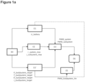
- a step E0 for activating or initializing the method can be provided.
- the method comprises a step E1' for reading the setpoint.
- this is a power setpoint P_(sub)system_target. It could also be a temperature setpoint T_(sub)system_target, or possibly a resistance setpoint R_(sub)system_target, or even an intensity setpoint i_(sub)system_target.
- the prefix "sub” is written in parentheses to signify that the setpoint concerns a subsystem, respectively all the resistive elements.
- the method may also include a step E1 in which the supply voltage U_battery is recorded or measured.
- This step E1 may be implemented by a voltage measurement sensor.
- the supply voltage U_battery may be constant.
- the method may include a step E2, in which the value of the intensity i_system_max or i_subsystem_max of the electric current flowing through a predefined number of resistive elements or even all of the resistive elements of the electric heating device is recorded or measured.
- This step E2 may be implemented by a current measurement sensor.
- the measured current is for example the maximum instantaneous current or at a peak, when the pulse width modulation control signal is at 100%.
- step E3 the duty cycle of the pulse width modulation control signal of the predefined number of resistive elements PWM_system or PWM_subsystem is recorded.
- PWM_(sub)system denotes the duty cycle of the pulse width modulation control signal for a subsystem, respectively for all the resistive elements.
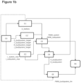
- the method may comprise a step E4 (see Figure 1b ), in which the value of at least one parameter is calculated for monitoring overheating of the electric heating device.
- this parameter is a function of the intensity of the electric current flowing through the predefined number of resistive elements i_subsystem_max, or even all of the resistive elements i_system_max, for monitoring overheating of the electric heating device.
- This step E4 can be implemented by a processing means such as a computer. This can be the actual value of the parameter.
- the value of the parameter can be calculated from the intensity of the electric current i_system_max; i_subsystem_max flowing through the predefined number of resistive elements measured in step E2.
- the supply voltage U_battery measured in step E1, when this step E1 is implemented, can further be taken into account in the calculation of step E4.
- one or the parameter may be a function of the recorded value of the duty cycle of the pulse width modulation control signal of the predefined number of PWM resistive elements _(sub)system.
- This step E4 can be carried out for one or more subsystems, i.e. for one or more sets of heating modules controlled by one or more transistors, or for the entire system, i.e. all of the resistive elements for all of the heating modules.
- the parameter can be the electrical resistance of the predefined number of resistive elements R_system; R_subsystem, the electrical power of the predefined number of resistive elements P_system; P_subsystem, the intensity of the electrical current traversing the predefined number of resistive elements i_system_max; i_subsystem_max, a multiple or a power of the intensity of the electric current traversing the predefined number of resistive elements.
- calculation step E4 is implemented when the chosen parameter is not the intensity of the electric current.
- the parameter may not be a function of the electric current intensity. It could be, for example, the temperature of the resistive elements.
- step E5 a threshold value for detecting the duty cycle of the control signal by pulse width modulation of the predefined number of resistive elements PWM_(sub)system_lim is defined, the detection threshold value being representative of overheating of the electric heating device.
- This threshold value for detecting said duty cycle PWM_(sub)system_lim can be defined as a function of the setpoint, preferably the power setpoint P_(sub)system_target, noted in step E1', as shown diagrammatically in the Figure 1a .
- the PWM detection threshold value _(sub)system_lim may be defined as a function of the torque of the measured supply voltage U_battery E1 and the setpoint, preferably the power setpoint P_(sub)system_target, taken in step E1'.
- both step E1 and step E1' are implemented beforehand, as shown diagrammatically by the dotted arrow between E1 and E5 and the solid arrow between E1' and E5 on the Figure 1a .
- the duty cycle detection threshold value PWM_(sub)system_lim can be defined as a function of the value of the chosen parameter calculated in step E4, as shown diagrammatically in Figure 1b , or the value of the electric current intensity recorded in step E2.
- the detection threshold value can also be defined as a function of the couple of the supply voltage U_battery measured in step E1 and the value of the chosen parameter that was calculated in step E4.
- both step E1 and step E4 are implemented beforehand, as shown by the dotted arrow between E1 and E5 and the solid arrow between E4 and E5 on the Figure 1b .
- the threshold value of detection can also be defined as a function of the torque of the supply voltage U_battery measured in step E1 and the value of the electric current intensity recorded in step E2.
- step E6 the value recorded for the duty cycle PWM_(sub)system in step E3 is compared to the detection threshold value PWM_(sub)system_lim) defined in step E5 or predetermined.
- This step E6 can be implemented by a processing means such as a comparator. Depending on the comparison result, overheating can be detected. In other words, if the recorded value of the duty cycle reaches or exceeds the defined duty cycle detection threshold value, this corresponds to overheating of the device. The recorded value of the duty cycle can exceed the detection threshold value, being higher or lower, depending on the nature of this parameter and depending on the nature of the resistive elements. In this case, one or more actions against this overheating, not detailed below, can be implemented. Otherwise, the steps of the method can be repeated until overheating is detected in step E6.
- a processing means such as a comparator.
- one or the parameter may be the electrical resistance of the heating modules.
- an electrical resistance value of the predefined number of resistive elements R_system; R_subsystem may be calculated from the measured supply voltage U_battery and the electrical current intensity i_system_max; i_subsystem_max.
- R_(sub)system denotes the electrical resistance value for a subsystem, respectively for all the resistive elements.
- the PWM duty cycle detection threshold value _(sub)system_lim is determined in step E5 as a function of the electrical resistance value of the predefined number of resistive elements R_(sub)system calculated in step E4 and possibly also from the supply voltage U_battery measured in step E1.
- This determination can be made for one or more subsystems, i.e. for one or more sets of heating modules controlled by one or more transistors, or for the entire system, i.e. all the resistive elements for all the heating modules.
- step E6 the value of the duty cycle PWM_(sub)system recorded in step E3 is compared with the detection threshold value PWM_(sub)system_lim) thus determined in step E5.
- one or the parameter may be the electrical power of the predefined number of resistive elements.
- This second approach may be implemented as an alternative or in addition to the first approach.
- step E4 an electrical power value of the predefined number of resistive elements P_system; P_subsystem can be calculated from the measured supply voltage (U_battery) and current intensity i_system_max; i_subsystem_max.
- the duty cycle recorded in step E3 is also taken into account for the calculation of the electrical power in step E4.
- the electrical power can be calculated by taking the product of the instantaneous electrical current intensity, the supply voltage and the duty cycle.
- the PWM duty cycle detection threshold value _(sub)system_lim can be determined in step E5 as a function of this electrical power value of the predefined number of resistive elements P_(sub)system calculated in step E4 and possibly of the supply voltage U_battery measured in step E1.
- step E6 the value of the duty cycle PWM_(sub)system recorded in step E3 is compared with the detection threshold value PWM_(sub)system_lim) thus determined in step E5.
- one or the parameter may be the intensity of the electric current flowing through the predefined number of resistive elements.
- This third approach may be implemented as an alternative or in addition to the first approach and/or the second approach.
- This third approach differs from the second approach in that there is no calculation step E4 but the value of the parameter is measured in step E2.
- the duty cycle detection threshold value PWM_(sub)system_lim can be determined in step E5 based on the current value i_system_max or i_subsystem_max measured in step E2 and possibly the supply voltage U_battery measured in step E1.
- step E6 the value of the duty cycle PWM_(sub)system recorded in step E3 is compared with the detection threshold value PWM_(sub)system_lim) thus determined in step E5.
- the parameter can also be a multiple or a power of the intensity of the electric current flowing through the predefined number of resistive elements. Examples include, but are not limited to, the square or cube of the intensity of the electric current, twice the intensity of the electric current, or the ratio of the intensity of the electric current to the duty cycle of the pulse width modulation control signal.
- the value of such a parameter can for example be measured.
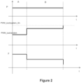
- This graph illustrates different operating phases of the electric heating device comprising a predefined number of heating modules, each comprising resistive elements, for example of the positive temperature coefficient (PTC) type.
- the curves of the electrical power P, the duty cycle of the PWM_(sub)system control signal, and the air flow F are shown diagrammatically.
- phase A the device operates without anomaly, under normal operating conditions, in particular with regard to the air flow rate and the air flow temperature.
- Phase B corresponds to a first drop in air flow as represented by curve F, this drop in air flow.
- step B the duty cycle of the PWM_(sub)system pulse width modulation control signal increases to avoid a drop in power, without however reaching the PWM _(sub)system_lim duty cycle detection threshold value defined in step E5 (also referring to the Figure 1a Or 1b ).
- the air flow not being too low, this compensation allows power to be maintained during phase B.
- the graph shows a second drop in airflow at the end of phase B.
- the duty cycle of the pulse width modulation control signal PWM_(sub)system increases further to avoid a power drop.
- the duty cycle cannot increase beyond the duty cycle detection threshold value PWM_(sub)system_lim set in step E5.
- this duty cycle detection threshold value PWM_(sub)system_lim this corresponds to the detection of device overheating in step E6.
- the measured duty cycle value exceeds the set duty cycle detection threshold value, i.e., is higher.
- steps E0 to E6 have been indexed, first step, second step, and so on. This is a simple indexing to differentiate and name the different steps of the process. This indexing does not necessarily imply a priority of one step over another. The order of certain steps of this process can be reversed without departing from the scope of this description. This indexing also does not imply an order in time. Certain steps can for example be carried out at the same time.
- the method according to one or other of the variants described above may further comprise at least one verification step, in which it is verified whether a criterion of the electric heating device is representative of a cold state.
- the criterion is, for example, the temperature of an electrical circuit support on which a power supply circuit for resistive elements is mounted.
- the temperature of the electrical circuit support is recorded, for example by a temperature sensor, such as a negative temperature coefficient thermal probe.
- the measured temperature reaches or exceeds a predefined threshold representative of minimal heating of the electric heating device, this confirms that the device is ready to be detected.
- the method may include a step for inhibiting at least the overheating detection step as long as the criterion, such as the electrical circuit support temperature, is representative of this cold state.
- the predefined threshold can be a minimum value below which no attempt is made to detect overheating.
- Such a check can for example be carried out at step E0.
- the implementation of the overheating detection method as described above can be carried out by a control unit.
- the overheating detection method can be implemented by the control unit already provided for controlling the heating modules of the electric heating device.
- control unit is therefore configured to monitor overheating according to the detection method described above.
- control unit comprises at least one processing means for implementing the steps of the method described above.
- control unit comprises one or more processing means for reading the power setpoint P_(sub)system_target, or temperature T_(sub)system_target, or resistance R_(sub)system_target, or even electric current intensity i_(sub)system_target.
- the control unit includes, for example, a voltage measuring sensor to measure or read the supply voltage U_battery.
- the control unit includes, for example, a current measuring sensor to measure or record the current i_(sub)system_max flowing through the predefined number of resistive elements or even all of the resistive elements.
- the control unit comprises, for example, processing means for determining or reading the duty cycle of the pulse width modulation control signal of the predefined number of resistive elements PWM_(sub)system.
- the control unit may further comprise one or more calculation means, for example for calculating the value of at least one parameter depending on the intensity of the electric current flowing through the predefined number of resistive elements i_system_max; i_subsystem_max for monitoring overheating of the electric heating device when this parameter is different from the intensity of the electric current, in particular from the measurement of the current i_(sub)system_max and possibly the supply voltage U_battery.
- one or more calculation means for example for calculating the value of at least one parameter depending on the intensity of the electric current flowing through the predefined number of resistive elements i_system_max; i_subsystem_max for monitoring overheating of the electric heating device when this parameter is different from the intensity of the electric current, in particular from the measurement of the current i_(sub)system_max and possibly the supply voltage U_battery.
- the or other calculation means may also be configured to define a threshold value for detecting the duty cycle of the control signal by pulse width modulation of the predefined number of resistive elements PWM_(sub)system_lim, the threshold value being representative of overheating of the electric heating device and being defined as a function of the setpoint or a value of at least one parameter depending on the intensity of the electric current for monitoring overheating of the electric heating device possibly previously calculated, or alternatively as a function of the couple of the supply voltage and the setpoint or the value of the parameter.
- the control unit comprises, for example, at least one comparator for comparing the recorded value of said duty cycle PWM_(sub)system with the detection threshold value PWM_(sub)system_lim.
- the control unit may include a calculation means or microprocessor for determining, based on the results of the comparisons, whether there is overheating.
- the microprocessor may evaluate whether the recorded value of said duty cycle is greater than or equal to said defined duty cycle detection threshold value.
- the control unit may also comprise at least one processing means for verifying whether a criterion of the electric heating device is representative of a cold state of the device.
- an additional temperature sensor may be provided.
- the control unit may include this additional temperature sensor.
- a temperature sensor may be placed on the PCB, for example by being soldered, brazed, or glued. It may be a negative temperature coefficient (NTC) temperature sensor whose electrical resistance decreases uniformly with temperature. Alternatively, it could This is a positive temperature coefficient (PTC) thermal probe, whose electrical resistance increases significantly with temperature.
- NTC negative temperature coefficient
- PTC positive temperature coefficient
- the control unit may comprise, for example, a comparator for comparing the temperature of the electrical circuit support recorded with a predefined threshold representative of minimal heating of the electric heating device. As long as the temperature recorded does not reach this predefined threshold, this is representative of a cold state of said device, and the control unit may comprise processing means for inhibiting the detection of overheating.
- the method according to the invention makes it possible to indirectly detect overheating in real time when the duty cycle reaches a detection threshold value. This makes it possible to prevent the electric heating device from reaching such a high temperature level that even without triggering a fire it would risk damaging certain surrounding components.
Landscapes
- Physics & Mathematics (AREA)
- General Physics & Mathematics (AREA)
- Engineering & Computer Science (AREA)
- Automation & Control Theory (AREA)
- Control Of Resistance Heating (AREA)
- Air-Conditioning For Vehicles (AREA)
- Safety Devices In Control Systems (AREA)
Claims (13)
- Verfahren zur Erkennung einer Überhitzung für eine elektrische Heizvorrichtung, die eine Mehrzahl von Widerstandselementen beinhaltet, die dazu ausgestaltet sind, von einer elektrischen Spannungsquelle elektrisch versorgt zu werden, wobei die elektrische Versorgung der Widerstandselemente mithilfe eines pulsweitenmodulierten Ansteuerungssignals in Abhängigkeit von einem Sollwert einer Leistung (P_(sub)system_target) oder einer Temperatur (T_(sub)system_target) oder eines Widerstands (R_(sub)system_target) oder einer elektrischen Stromstärke (i_(sub)system_target) angesteuert wird, wobei das Verfahren die folgenden Schritte umfasst:- Überprüfen, ob mindestens ein Kriterium der Vorrichtung für einen kalten Zustand der Vorrichtung repräsentativ ist, und Unterbinden mindestens des folgenden Schritts zur Erkennung einer Überhitzung, wenn das mindestens eine Kriterium für einen kalten Zustand repräsentativ ist,- Erfassen des Sollwerts (P_(sub)system_target, T_(sub) system_target, R_(sub)system_target, i_(sub)system_target),- Erfassen des Tastverhältnisses des pulsweitenmodulierten Ansteuerungssignals der vorgegebenen Anzahl von Widerstandselementen (PWM_system; PWM_subsystem),- Festlegen eines Tastverhältnis-Erkennungsschwellenwerts des pulsweitenmodulierten Ansteuerungssignals der vorgegebenen Anzahl von Widerstandselementen (PWM_system_lim; PWM_subsystem_lim), wobei der Erkennungsschwellenwert für eine Überhitzung der elektrischen Heizvorrichtung repräsentativ ist, wobei der Erkennungsschwellenwert in Abhängigkeit von dem Sollwert oder von einem Wert mindestens eines Parameters für die Überwachung einer Überhitzung der elektrischen Heizvorrichtung festgelegt wird,- Vergleichen des erfassten Werts des Tastverhältnisses (PWM_system; PWM_subsystem) mit dem Erkennungsschwellenwert (PWM_system_lim; PWM_subsystem_lim), und- Erkennen einer Überhitzung, wenn der erfasste Wert des Tastverhältnisses den festgelegten Tastverhältnis-Erkennungsschwellenwert erreicht.
- Verfahren nach dem vorhergehenden Anspruch, beinhaltend einen zusätzlichen Schritt zum Messen des Werts der Stärke (i_system _max; i_subsystem _max) des elektrischen Stroms, der durch eine vorgegebene Anzahl von Widerstandselementen fließt.
- Verfahren nach Anspruch 2, wobei der mindestens eine Parameter für die Überwachung einer Überhitzung der elektrischen Heizvorrichtung von der Stärke des elektrischen Stroms (i_(sub)system_max) abhängig ist, wobei der Wert des mindestens einen Parameters berechnet wird, wenn der mindestens eine Parameter verschieden von der Stärke des elektrischen Stroms ist.
- Verfahren nach einem der vorhergehenden Ansprüche, umfassend einen Schritt zum Messen der Versorgungsspannung (U_battery).
- Verfahren nach Anspruch 4, wobei der Tastverhältnis-Erkennungsschwellenwert des pulsweitenmodulierten Ansteuerungssignals der vorgegebenen Anzahl von Widerstandselementen (PWM_system_lim; PWM_subsystem_lim) auch in Abhängigkeit von der gemessenen Versorgungsspannung (U_battery) bestimmt wird.
- Verfahren nach einem der vorhergehenden Ansprüche, wobei die elektrische Versorgung von einem Leistungssollwert (P_(sub)system_target) abhängig ist und wobei der Erkennungsschwellenwert in Abhängigkeit von dem Leistungssollwert (P_(sub)system_target) festgelegt wird.
- Verfahren nach dem vorhergehenden Anspruch, wobei der Leistungssollwert (P_(sub)system_target) von einem Temperatursollwert (T_(sub)system_target) abhängig ist.
- Verfahren nach Anspruch 4 in Verbindung mit einem der vorhergehenden Ansprüche, wobei, wenn der mindestens eine Parameter verschieden von der Stärke des elektrischen Stroms ist, der Wert des mindestens einen Parameters ausgehend von der gemessenen Versorgungsspannung (U_battery) und von der gemessenen Stärke des elektrischen Stroms (i_system_max; i_subsystem_max), der durch die vorgegebene Anzahl von Widerstandselementen fließt, berechnet wird.
- Verfahren nach einem der vorhergehenden Ansprüche, wobei der mindestens eine Parameter gewählt wird aus:dem elektrischen Widerstand der vorgegebenen Anzahl von Widerstandselementen (R_system; R_subsystem),der Stärke des elektrischen Stroms, der durch die vorgegebene Anzahl von Widerstandselementen fließt (i_system_max; i_subsystem_max), einem Vielfachen oder einer Leistung der Stärke des elektrischen Stroms, der durch die vorgegebene Anzahl von Widerstandselementen fließt (i_system_max; i_subsystem_max), undder elektrischen Leistung der vorgegebenen Anzahl von Widerstandselementen (P_system; P_subsystem).
- Verfahren nach einem der vorhergehenden Ansprüche, wobei die Widerstandselemente vom Typ mit positivem oder negativem Temperaturkoeffizienten sind.
- Verfahren nach einem der vorhergehenden Ansprüche, wobei die gemessene Stärke (i_system_max; i_subsystem_max) des elektrischen Stroms die Stärke des momentanen elektrischen Stroms ist, der durch die vorgegebene Anzahl von Widerstandselementen fließt, wenn das pulsweitenmodulierte Ansteuerungssignal 100 % beträgt.
- Verfahren nach einem der vorhergehenden Ansprüche, wobei:- mindestens zwei unterschiedliche Teilmengen von Widerstandselementen im Hinblick auf die elektrische Versorgung unabhängig pulsweitenmoduliert angesteuert werden, und wobei- für jede Teilmenge ein Tastverhältnis-Erkennungsschwellenwert des Ansteuerungssignals je nach Art und/oder Anzahl der Widerstandselemente der Teilmenge unabhängig festgelegt wird.
- Steuerungseinheit für eine elektrische Heizvorrichtung, die eine Mehrzahl von Widerstandselementen umfasst, die dazu ausgestaltet sind, von einer elektrischen Spannungsquelle elektrisch versorgt zu werden, wobei die Steuerungseinheit dazu ausgestaltet ist, ein pulsweitenmoduliertes Ansteuerungssignal für die elektrische Versorgung der Widerstandselemente in Abhängigkeit von einem Sollwert einer Leistung (P_(sub)system_target) oder einer Temperatur (T_(sub)system_target) oder eines Widerstands (R_(sub) system_target) oder einer elektrischen Stromstärke (i_(sub)system_target) zu erzeugen, wobei die Steuerungseinheit mindestens ein Verarbeitungsmittel beinhaltet zum:- Überprüfen, ob mindestens ein Kriterium der Vorrichtung für einen kalten Zustand der Vorrichtung repräsentativ ist, und Unterbinden mindestens des folgenden Schritts zur Erkennung einer Überhitzung, wenn das mindestens eine Kriterium für einen kalten Zustand repräsentativ ist,- Erfassen des Sollwerts (P_(sub)system_target, T_(sub)system_target, R_(sub)system_target, i_(sub)system_target),- Erfassen des Tastverhältnisses des pulsweitenmodulierten Ansteuerungssignals der vorgegebenen Anzahl von Widerstandselementen (PWM_system; PWM_subsystem),- Festlegen eines Tastverhältnis-Erkennungsschwellenwerts des pulsweitenmodulierten Ansteuerungssignals der vorgegebenen Anzahl von Widerstandselementen (PWM_system_lim; PWM_subsystem_lim), wobei der Erkennungsschwellenwert für eine Überhitzung der elektrischen Heizvorrichtung repräsentativ ist, in Abhängigkeit von dem Sollwert oder von einem Wert mindestens eines Parameters für die Überwachung einer Überhitzung der elektrischen Heizvorrichtung,- Vergleichen des erfassten Werts des Tastverhältnisses (PWM_system; PWM_subsystem) mit dem Erkennungsschwellenwert (PWM_system_lim; PWM_subsystem_lim), und- Erkennen einer Überhitzung, wenn der erfasste Wert des Tastverhältnisses den festgelegten Tastverhältnis-Schwellenwert erreicht.
Applications Claiming Priority (2)
| Application Number | Priority Date | Filing Date | Title |
|---|---|---|---|
| FR1860226A FR3088121B1 (fr) | 2018-11-06 | 2018-11-06 | Procede de detection de surchauffe pour dispositif de chauffage et unite de commande correspondante |
| PCT/FR2019/052616 WO2020094969A1 (fr) | 2018-11-06 | 2019-11-05 | Procédé de détection de surchauffe pour dispositif de chauffage et unité de commande correspondante |
Publications (2)
| Publication Number | Publication Date |
|---|---|
| EP3877772A1 EP3877772A1 (de) | 2021-09-15 |
| EP3877772B1 true EP3877772B1 (de) | 2025-06-18 |
Family
ID=65951661
Family Applications (1)
| Application Number | Title | Priority Date | Filing Date |
|---|---|---|---|
| EP19818214.9A Active EP3877772B1 (de) | 2018-11-06 | 2019-11-05 | Verfahren zur erkennung einer überhitzung einer heizvorrichtung und entsprechende steuereinheit |
Country Status (6)
| Country | Link |
|---|---|
| US (1) | US12253866B2 (de) |
| EP (1) | EP3877772B1 (de) |
| JP (1) | JP7138789B2 (de) |
| CN (1) | CN112840216B (de) |
| FR (1) | FR3088121B1 (de) |
| WO (1) | WO2020094969A1 (de) |
Families Citing this family (2)
| Publication number | Priority date | Publication date | Assignee | Title |
|---|---|---|---|---|
| CN114583661B (zh) * | 2022-04-19 | 2024-03-19 | 潍柴动力股份有限公司 | 一种阀体的电机的过热保护方法及发动机后处理系统 |
| CN115218287B (zh) * | 2022-07-05 | 2025-11-18 | 青岛海尔空调器有限总公司 | 一种空调器及其控制方法 |
Family Cites Families (21)
| Publication number | Priority date | Publication date | Assignee | Title |
|---|---|---|---|---|
| JP4454972B2 (ja) | 2003-06-30 | 2010-04-21 | キヤノン株式会社 | 画像形成装置 |
| JP2007059097A (ja) * | 2005-08-22 | 2007-03-08 | Eiwa Denki Kk | ヒータコントローラシステム |
| JP4732191B2 (ja) * | 2006-02-28 | 2011-07-27 | 矢崎総業株式会社 | 過熱保護機能付き半導体装置の制御回路 |
| KR100894008B1 (ko) * | 2007-11-16 | 2009-04-17 | 모딘코리아 유한회사 | 자동차의 보조전기가열장치 및 방법 |
| DE102008018808A1 (de) | 2008-04-15 | 2009-10-22 | Ledon Lighting Jennersdorf Gmbh | Mikrocontroller optimierte Pulsweitenmodulation-(PWM)-Ansteuerung einer Licht emittierenden Diode(LED) |
| EP2123901B1 (de) | 2008-05-21 | 2013-08-28 | GM Global Technology Operations LLC | Verfahren zur Steuerung des Betriebs einer Zündkerze in einem Dieselmotor |
| KR101065482B1 (ko) * | 2009-06-04 | 2011-09-19 | 주식회사 보국전자 | 안전장치가 부가된 전열기구의 온도제어장치 |
| EP2371588B1 (de) * | 2010-03-26 | 2012-10-10 | Eberspächer catem GmbH & Co. KG | Elektrische Heizvorrichtung |
| DE102010042013A1 (de) | 2010-10-06 | 2012-04-12 | Robert Bosch Gmbh | Verfahren zur Einstellung einer Temperatur eines Sensorelements |
| JP5827535B2 (ja) * | 2011-10-12 | 2015-12-02 | サンデンホールディングス株式会社 | 車載暖房用ヒータの制御装置 |
| DE102012219244A1 (de) | 2012-10-22 | 2014-04-24 | Robert Bosch Gmbh | Verfahren und Vorrichtung zur Leistungssteuerung eines elektrischen Verbrauchers |
| GB2512041A (en) | 2012-12-31 | 2014-09-24 | Continental Automotive Systems | Resistance determination for temperature control of heated automotive components |
| JP2014136462A (ja) | 2013-01-15 | 2014-07-28 | Toyota Boshoku Corp | ヒータ制御装置 |
| EP2772820B1 (de) * | 2013-02-27 | 2015-04-08 | Eberspächer catem GmbH & Co. KG | Elektrische Heizvorrichtung für ein Kraftfahrzeug |
| JP2014181012A (ja) | 2013-03-21 | 2014-09-29 | Tokai Rika Co Ltd | 車載用負荷過熱防止装置 |
| FR3007229B1 (fr) | 2013-06-17 | 2015-06-19 | Valeo Systemes Thermiques | Commande d'un circuit de chauffage electrique, notamment pour vehicule automobile |
| JP6384129B2 (ja) | 2013-08-27 | 2018-09-05 | 株式会社デンソー | 車載用輻射ヒータ制御装置 |
| EP3093659B1 (de) | 2015-05-11 | 2017-06-14 | Siemens Aktiengesellschaft | Wärmeleitfähigkeitsdetektor und verfahren zum betrieb davon |
| DE102016109039A1 (de) * | 2016-02-17 | 2017-08-17 | Dbk David + Baader Gmbh | Elektrische Vorrichtung, insbesondere Heizer, sowie Vorrichtung und Verfahren zur Ansteuerung einer elektrischen Vorrichtung |
| DE102016216295A1 (de) * | 2016-08-30 | 2018-03-01 | Dbk David + Baader Gmbh | Elektrischer heizer und verfahren zum erkennen einer überhitzung eines solchen elektrischen heizers |
| FR3062601B1 (fr) * | 2017-02-06 | 2019-06-07 | Valeo Systemes Thermiques | Dispositif de chauffage electrique, circuit de chauffage et procede de gestion de la temperature correspondants |
-
2018
- 2018-11-06 FR FR1860226A patent/FR3088121B1/fr active Active
-
2019
- 2019-11-05 EP EP19818214.9A patent/EP3877772B1/de active Active
- 2019-11-05 WO PCT/FR2019/052616 patent/WO2020094969A1/fr not_active Ceased
- 2019-11-05 JP JP2021523714A patent/JP7138789B2/ja active Active
- 2019-11-05 CN CN201980067824.1A patent/CN112840216B/zh active Active
- 2019-11-05 US US17/291,502 patent/US12253866B2/en active Active
Also Published As
| Publication number | Publication date |
|---|---|
| FR3088121B1 (fr) | 2020-11-13 |
| FR3088121A1 (fr) | 2020-05-08 |
| JP7138789B2 (ja) | 2022-09-16 |
| CN112840216A (zh) | 2021-05-25 |
| US12253866B2 (en) | 2025-03-18 |
| JP2022506379A (ja) | 2022-01-17 |
| WO2020094969A1 (fr) | 2020-05-14 |
| CN112840216B (zh) | 2025-01-14 |
| US20220004212A1 (en) | 2022-01-06 |
| EP3877772A1 (de) | 2021-09-15 |
Similar Documents
| Publication | Publication Date | Title |
|---|---|---|
| EP3577395B1 (de) | Elektrische heizvorrichtung, heizkreis und verfahren zur steureung der entsprechenden temperaturen | |
| EP3877772B1 (de) | Verfahren zur erkennung einer überhitzung einer heizvorrichtung und entsprechende steuereinheit | |
| EP0042333B1 (de) | Regeleinrichtung einer Ventilationsanlage einer Brennkraftmaschine | |
| EP0782265B1 (de) | Verfahren und Vorrichtung zum Schutz eines einstellbaren Impedanzelements zur Steuerung der Stromversorgung eines Elektromotors, insbesondere eines Kraftfahrzeugs | |
| WO2015067730A2 (fr) | Commande sécurisée d'un réchauffeur électrique | |
| EP0194921B1 (de) | Elektrischer Motor mit Überstromschutzeinrichtung mit Thermistoren | |
| FR2987939A1 (fr) | Procede de gestion d'un systeme de vehicule automobile et systeme adapte a la mise en oeuvre du procede | |
| EP0054476B1 (de) | Sicherheitskreis für die Temperaturregelungsvorrichtung eines Kühlfluidums einer Brennkraftmaschine | |
| FR3088120A1 (fr) | Procede de detection de surchauffe pour dispositif de chauffage et unite de commande correspondante | |
| FR3088122A1 (fr) | Procede de detection de surchauffe pour dispositif de chauffage et unite de commande correspondante | |
| EP4038468B1 (de) | Thermisches management-prozess, insbesondere für ein kraftfahrzeug und zugehörige steuereinheit | |
| FR3101508A1 (fr) | Procédé de gestion thermique, notamment pour véhicule automobile, et unité de commande associée | |
| FR3101509A1 (fr) | Procédé de gestion thermique, notamment pour véhicule automobile, et unité de commande associée | |
| WO2021064309A1 (fr) | Procédé de gestion thermique, notamment pour véhicule automobile, et stratégie de gestion thermique et unité de commande associées | |
| WO1999048183A1 (fr) | Bloc de moteur electrique, notamment pour vehicule automobile, integrant une electronique de commande | |
| EP4305926A1 (de) | Steuermodul und zugehörige elektrische vorrichtung und verfahren zum erkennen des entfernens einer abdeckung von einem steuermodul | |
| EP3991002B1 (de) | Steuervorrichtung für ein fluidheizsystem | |
| WO2020193886A1 (fr) | Procede de diagnostic d'un systeme de refroidissement d'un circuit electrique de propulsion | |
| FR3126589A1 (fr) | Procede de limitation de tension de la tension efficace d’au moins un composant electrique et/ou electronique et systeme electronique correspondant | |
| EP3201576B1 (de) | Luftstromerkennungsvorrichtung | |
| FR3060493A1 (fr) | Systeme d’essuyage pour vehicule automobile | |
| EP1566643B1 (de) | Verfahren zur Prüfung einer Ausgangüberstrom einer elektrischen Ausrüstung, sowie zur Prüfung einer solchen Ausrüstung | |
| FR2655143A1 (fr) | Detecteur de niveau d'huile dans le carter d'un moteur de vehicule automobile. | |
| CH642199A5 (fr) | Dispositif de protection thermique d'un moteur electrique. |
Legal Events
| Date | Code | Title | Description |
|---|---|---|---|
| STAA | Information on the status of an ep patent application or granted ep patent |
Free format text: STATUS: UNKNOWN |
|
| STAA | Information on the status of an ep patent application or granted ep patent |
Free format text: STATUS: THE INTERNATIONAL PUBLICATION HAS BEEN MADE |
|
| PUAI | Public reference made under article 153(3) epc to a published international application that has entered the european phase |
Free format text: ORIGINAL CODE: 0009012 |
|
| STAA | Information on the status of an ep patent application or granted ep patent |
Free format text: STATUS: REQUEST FOR EXAMINATION WAS MADE |
|
| 17P | Request for examination filed |
Effective date: 20210506 |
|
| AK | Designated contracting states |
Kind code of ref document: A1 Designated state(s): AL AT BE BG CH CY CZ DE DK EE ES FI FR GB GR HR HU IE IS IT LI LT LU LV MC MK MT NL NO PL PT RO RS SE SI SK SM TR |
|
| DAV | Request for validation of the european patent (deleted) | ||
| DAX | Request for extension of the european patent (deleted) | ||
| P01 | Opt-out of the competence of the unified patent court (upc) registered |
Effective date: 20230528 |
|
| STAA | Information on the status of an ep patent application or granted ep patent |
Free format text: STATUS: EXAMINATION IS IN PROGRESS |
|
| 17Q | First examination report despatched |
Effective date: 20231220 |
|
| GRAP | Despatch of communication of intention to grant a patent |
Free format text: ORIGINAL CODE: EPIDOSNIGR1 |
|
| STAA | Information on the status of an ep patent application or granted ep patent |
Free format text: STATUS: GRANT OF PATENT IS INTENDED |
|
| INTG | Intention to grant announced |
Effective date: 20250114 |
|
| GRAS | Grant fee paid |
Free format text: ORIGINAL CODE: EPIDOSNIGR3 |
|
| GRAA | (expected) grant |
Free format text: ORIGINAL CODE: 0009210 |
|
| STAA | Information on the status of an ep patent application or granted ep patent |
Free format text: STATUS: THE PATENT HAS BEEN GRANTED |
|
| AK | Designated contracting states |
Kind code of ref document: B1 Designated state(s): AL AT BE BG CH CY CZ DE DK EE ES FI FR GB GR HR HU IE IS IT LI LT LU LV MC MK MT NL NO PL PT RO RS SE SI SK SM TR |
|
| REG | Reference to a national code |
Ref country code: GB Ref legal event code: FG4D Free format text: NOT ENGLISH |
|
| REG | Reference to a national code |
Ref country code: CH Ref legal event code: EP |
|
| REG | Reference to a national code |
Ref country code: DE Ref legal event code: R096 Ref document number: 602019071330 Country of ref document: DE |
|
| REG | Reference to a national code |
Ref country code: CH Ref legal event code: EP |
|
| REG | Reference to a national code |
Ref country code: IE Ref legal event code: FG4D Free format text: LANGUAGE OF EP DOCUMENT: FRENCH |
|
| PG25 | Lapsed in a contracting state [announced via postgrant information from national office to epo] |
Ref country code: FI Free format text: LAPSE BECAUSE OF FAILURE TO SUBMIT A TRANSLATION OF THE DESCRIPTION OR TO PAY THE FEE WITHIN THE PRESCRIBED TIME-LIMIT Effective date: 20250618 |
|
| REG | Reference to a national code |
Ref country code: LT Ref legal event code: MG9D |
|
| PG25 | Lapsed in a contracting state [announced via postgrant information from national office to epo] |
Ref country code: NO Free format text: LAPSE BECAUSE OF FAILURE TO SUBMIT A TRANSLATION OF THE DESCRIPTION OR TO PAY THE FEE WITHIN THE PRESCRIBED TIME-LIMIT Effective date: 20250918 Ref country code: GR Free format text: LAPSE BECAUSE OF FAILURE TO SUBMIT A TRANSLATION OF THE DESCRIPTION OR TO PAY THE FEE WITHIN THE PRESCRIBED TIME-LIMIT Effective date: 20250919 |
|
| PG25 | Lapsed in a contracting state [announced via postgrant information from national office to epo] |
Ref country code: BG Free format text: LAPSE BECAUSE OF FAILURE TO SUBMIT A TRANSLATION OF THE DESCRIPTION OR TO PAY THE FEE WITHIN THE PRESCRIBED TIME-LIMIT Effective date: 20250618 |
|
| PG25 | Lapsed in a contracting state [announced via postgrant information from national office to epo] |
Ref country code: HR Free format text: LAPSE BECAUSE OF FAILURE TO SUBMIT A TRANSLATION OF THE DESCRIPTION OR TO PAY THE FEE WITHIN THE PRESCRIBED TIME-LIMIT Effective date: 20250618 |
|
| PG25 | Lapsed in a contracting state [announced via postgrant information from national office to epo] |
Ref country code: RS Free format text: LAPSE BECAUSE OF FAILURE TO SUBMIT A TRANSLATION OF THE DESCRIPTION OR TO PAY THE FEE WITHIN THE PRESCRIBED TIME-LIMIT Effective date: 20250918 |
|
| REG | Reference to a national code |
Ref country code: NL Ref legal event code: MP Effective date: 20250618 |
|
| PG25 | Lapsed in a contracting state [announced via postgrant information from national office to epo] |
Ref country code: LV Free format text: LAPSE BECAUSE OF FAILURE TO SUBMIT A TRANSLATION OF THE DESCRIPTION OR TO PAY THE FEE WITHIN THE PRESCRIBED TIME-LIMIT Effective date: 20250618 |
|
| PG25 | Lapsed in a contracting state [announced via postgrant information from national office to epo] |
Ref country code: NL Free format text: LAPSE BECAUSE OF FAILURE TO SUBMIT A TRANSLATION OF THE DESCRIPTION OR TO PAY THE FEE WITHIN THE PRESCRIBED TIME-LIMIT Effective date: 20250618 |
|
| PG25 | Lapsed in a contracting state [announced via postgrant information from national office to epo] |
Ref country code: PT Free format text: LAPSE BECAUSE OF FAILURE TO SUBMIT A TRANSLATION OF THE DESCRIPTION OR TO PAY THE FEE WITHIN THE PRESCRIBED TIME-LIMIT Effective date: 20251020 |
|
| REG | Reference to a national code |
Ref country code: AT Ref legal event code: MK05 Ref document number: 1804638 Country of ref document: AT Kind code of ref document: T Effective date: 20250618 |
|
| PG25 | Lapsed in a contracting state [announced via postgrant information from national office to epo] |
Ref country code: IS Free format text: LAPSE BECAUSE OF FAILURE TO SUBMIT A TRANSLATION OF THE DESCRIPTION OR TO PAY THE FEE WITHIN THE PRESCRIBED TIME-LIMIT Effective date: 20251018 |
|
| PGFP | Annual fee paid to national office [announced via postgrant information from national office to epo] |
Ref country code: DE Payment date: 20251117 Year of fee payment: 7 |
|
| PG25 | Lapsed in a contracting state [announced via postgrant information from national office to epo] |
Ref country code: AT Free format text: LAPSE BECAUSE OF FAILURE TO SUBMIT A TRANSLATION OF THE DESCRIPTION OR TO PAY THE FEE WITHIN THE PRESCRIBED TIME-LIMIT Effective date: 20250618 Ref country code: SM Free format text: LAPSE BECAUSE OF FAILURE TO SUBMIT A TRANSLATION OF THE DESCRIPTION OR TO PAY THE FEE WITHIN THE PRESCRIBED TIME-LIMIT Effective date: 20250618 |
|
| PG25 | Lapsed in a contracting state [announced via postgrant information from national office to epo] |
Ref country code: CZ Free format text: LAPSE BECAUSE OF FAILURE TO SUBMIT A TRANSLATION OF THE DESCRIPTION OR TO PAY THE FEE WITHIN THE PRESCRIBED TIME-LIMIT Effective date: 20250618 |
|
| PG25 | Lapsed in a contracting state [announced via postgrant information from national office to epo] |
Ref country code: PL Free format text: LAPSE BECAUSE OF FAILURE TO SUBMIT A TRANSLATION OF THE DESCRIPTION OR TO PAY THE FEE WITHIN THE PRESCRIBED TIME-LIMIT Effective date: 20250618 |
|
| PG25 | Lapsed in a contracting state [announced via postgrant information from national office to epo] |
Ref country code: EE Free format text: LAPSE BECAUSE OF FAILURE TO SUBMIT A TRANSLATION OF THE DESCRIPTION OR TO PAY THE FEE WITHIN THE PRESCRIBED TIME-LIMIT Effective date: 20250618 |
|
| PG25 | Lapsed in a contracting state [announced via postgrant information from national office to epo] |
Ref country code: SK Free format text: LAPSE BECAUSE OF FAILURE TO SUBMIT A TRANSLATION OF THE DESCRIPTION OR TO PAY THE FEE WITHIN THE PRESCRIBED TIME-LIMIT Effective date: 20250618 Ref country code: RO Free format text: LAPSE BECAUSE OF FAILURE TO SUBMIT A TRANSLATION OF THE DESCRIPTION OR TO PAY THE FEE WITHIN THE PRESCRIBED TIME-LIMIT Effective date: 20250618 |
|
| PG25 | Lapsed in a contracting state [announced via postgrant information from national office to epo] |
Ref country code: ES Free format text: LAPSE BECAUSE OF FAILURE TO SUBMIT A TRANSLATION OF THE DESCRIPTION OR TO PAY THE FEE WITHIN THE PRESCRIBED TIME-LIMIT Effective date: 20250618 |
|
| REG | Reference to a national code |
Ref country code: CH Ref legal event code: W10 Free format text: ST27 STATUS EVENT CODE: U-0-0-W10-W00 (AS PROVIDED BY THE NATIONAL OFFICE) Effective date: 20260218 |
|
| RAP2 | Party data changed (patent owner data changed or rights of a patent transferred) |
Owner name: VALEO ELECTRIFICATION |
|
| PG25 | Lapsed in a contracting state [announced via postgrant information from national office to epo] |
Ref country code: DK Free format text: LAPSE BECAUSE OF FAILURE TO SUBMIT A TRANSLATION OF THE DESCRIPTION OR TO PAY THE FEE WITHIN THE PRESCRIBED TIME-LIMIT Effective date: 20250618 |
|
| PG25 | Lapsed in a contracting state [announced via postgrant information from national office to epo] |
Ref country code: IT Free format text: LAPSE BECAUSE OF FAILURE TO SUBMIT A TRANSLATION OF THE DESCRIPTION OR TO PAY THE FEE WITHIN THE PRESCRIBED TIME-LIMIT Effective date: 20250618 |
|
| PLBE | No opposition filed within time limit |
Free format text: ORIGINAL CODE: 0009261 |
|
| STAA | Information on the status of an ep patent application or granted ep patent |
Free format text: STATUS: NO OPPOSITION FILED WITHIN TIME LIMIT |