EP3990761B1 - Valve device for an internal combustion engine - Google Patents
Valve device for an internal combustion engine Download PDFInfo
- Publication number
- EP3990761B1 EP3990761B1 EP19735255.2A EP19735255A EP3990761B1 EP 3990761 B1 EP3990761 B1 EP 3990761B1 EP 19735255 A EP19735255 A EP 19735255A EP 3990761 B1 EP3990761 B1 EP 3990761B1
- Authority
- EP
- European Patent Office
- Prior art keywords
- valve
- diaphragm
- valve device
- combustion engine
- internal combustion
- Prior art date
- Legal status (The legal status is an assumption and is not a legal conclusion. Google has not performed a legal analysis and makes no representation as to the accuracy of the status listed.)
- Active
Links
- 238000002485 combustion reaction Methods 0.000 title claims description 22
- 125000006850 spacer group Chemical group 0.000 claims description 29
- 230000036961 partial effect Effects 0.000 claims description 15
- 230000000630 rising effect Effects 0.000 claims description 3
- 239000012528 membrane Substances 0.000 description 66
- 239000007789 gas Substances 0.000 description 8
- 239000007788 liquid Substances 0.000 description 5
- 230000015572 biosynthetic process Effects 0.000 description 4
- 230000005484 gravity Effects 0.000 description 3
- 239000000126 substance Substances 0.000 description 3
- 239000000356 contaminant Substances 0.000 description 2
- 238000011109 contamination Methods 0.000 description 2
- 230000008020 evaporation Effects 0.000 description 2
- 238000001704 evaporation Methods 0.000 description 2
- 230000008014 freezing Effects 0.000 description 2
- 238000007710 freezing Methods 0.000 description 2
- 238000004519 manufacturing process Methods 0.000 description 2
- 238000000034 method Methods 0.000 description 2
- 238000007664 blowing Methods 0.000 description 1
- 238000010276 construction Methods 0.000 description 1
- 230000007797 corrosion Effects 0.000 description 1
- 238000005260 corrosion Methods 0.000 description 1
- 239000003344 environmental pollutant Substances 0.000 description 1
- 239000012535 impurity Substances 0.000 description 1
- 230000000670 limiting effect Effects 0.000 description 1
- 230000007257 malfunction Effects 0.000 description 1
- 231100000719 pollutant Toxicity 0.000 description 1
- 230000010349 pulsation Effects 0.000 description 1
- 230000002829 reductive effect Effects 0.000 description 1
- 230000000717 retained effect Effects 0.000 description 1
- 230000002441 reversible effect Effects 0.000 description 1
- 238000007789 sealing Methods 0.000 description 1
- 238000009827 uniform distribution Methods 0.000 description 1
- XLYOFNOQVPJJNP-UHFFFAOYSA-N water Substances O XLYOFNOQVPJJNP-UHFFFAOYSA-N 0.000 description 1
Images
Classifications
-
- F—MECHANICAL ENGINEERING; LIGHTING; HEATING; WEAPONS; BLASTING
- F01—MACHINES OR ENGINES IN GENERAL; ENGINE PLANTS IN GENERAL; STEAM ENGINES
- F01N—GAS-FLOW SILENCERS OR EXHAUST APPARATUS FOR MACHINES OR ENGINES IN GENERAL; GAS-FLOW SILENCERS OR EXHAUST APPARATUS FOR INTERNAL COMBUSTION ENGINES
- F01N3/00—Exhaust or silencing apparatus having means for purifying, rendering innocuous, or otherwise treating exhaust
- F01N3/08—Exhaust or silencing apparatus having means for purifying, rendering innocuous, or otherwise treating exhaust for rendering innocuous
- F01N3/10—Exhaust or silencing apparatus having means for purifying, rendering innocuous, or otherwise treating exhaust for rendering innocuous by thermal or catalytic conversion of noxious components of exhaust
- F01N3/18—Exhaust or silencing apparatus having means for purifying, rendering innocuous, or otherwise treating exhaust for rendering innocuous by thermal or catalytic conversion of noxious components of exhaust characterised by methods of operation; Control
- F01N3/22—Control of additional air supply only, e.g. using by-passes or variable air pump drives
- F01N3/227—Control of additional air supply only, e.g. using by-passes or variable air pump drives using pneumatically operated valves, e.g. membrane valves
-
- F—MECHANICAL ENGINEERING; LIGHTING; HEATING; WEAPONS; BLASTING
- F01—MACHINES OR ENGINES IN GENERAL; ENGINE PLANTS IN GENERAL; STEAM ENGINES
- F01N—GAS-FLOW SILENCERS OR EXHAUST APPARATUS FOR MACHINES OR ENGINES IN GENERAL; GAS-FLOW SILENCERS OR EXHAUST APPARATUS FOR INTERNAL COMBUSTION ENGINES
- F01N3/00—Exhaust or silencing apparatus having means for purifying, rendering innocuous, or otherwise treating exhaust
- F01N3/08—Exhaust or silencing apparatus having means for purifying, rendering innocuous, or otherwise treating exhaust for rendering innocuous
- F01N3/10—Exhaust or silencing apparatus having means for purifying, rendering innocuous, or otherwise treating exhaust for rendering innocuous by thermal or catalytic conversion of noxious components of exhaust
- F01N3/24—Exhaust or silencing apparatus having means for purifying, rendering innocuous, or otherwise treating exhaust for rendering innocuous by thermal or catalytic conversion of noxious components of exhaust characterised by constructional aspects of converting apparatus
- F01N3/30—Arrangements for supply of additional air
-
- F—MECHANICAL ENGINEERING; LIGHTING; HEATING; WEAPONS; BLASTING
- F02—COMBUSTION ENGINES; HOT-GAS OR COMBUSTION-PRODUCT ENGINE PLANTS
- F02M—SUPPLYING COMBUSTION ENGINES IN GENERAL WITH COMBUSTIBLE MIXTURES OR CONSTITUENTS THEREOF
- F02M23/00—Apparatus for adding secondary air to fuel-air mixture
- F02M23/006—Valves specially shaped for supplying secondary air
-
- F—MECHANICAL ENGINEERING; LIGHTING; HEATING; WEAPONS; BLASTING
- F02—COMBUSTION ENGINES; HOT-GAS OR COMBUSTION-PRODUCT ENGINE PLANTS
- F02M—SUPPLYING COMBUSTION ENGINES IN GENERAL WITH COMBUSTIBLE MIXTURES OR CONSTITUENTS THEREOF
- F02M23/00—Apparatus for adding secondary air to fuel-air mixture
- F02M23/04—Apparatus for adding secondary air to fuel-air mixture with automatic control
- F02M23/08—Apparatus for adding secondary air to fuel-air mixture with automatic control dependent on pressure in main combustion-air induction system, e.g. pneumatic-type apparatus
- F02M23/09—Apparatus for adding secondary air to fuel-air mixture with automatic control dependent on pressure in main combustion-air induction system, e.g. pneumatic-type apparatus using valves directly opened by low pressure
-
- F—MECHANICAL ENGINEERING; LIGHTING; HEATING; WEAPONS; BLASTING
- F02—COMBUSTION ENGINES; HOT-GAS OR COMBUSTION-PRODUCT ENGINE PLANTS
- F02M—SUPPLYING COMBUSTION ENGINES IN GENERAL WITH COMBUSTIBLE MIXTURES OR CONSTITUENTS THEREOF
- F02M26/00—Engine-pertinent apparatus for adding exhaust gases to combustion-air, main fuel or fuel-air mixture, e.g. by exhaust gas recirculation [EGR] systems
- F02M26/52—Systems for actuating EGR valves
- F02M26/55—Systems for actuating EGR valves using vacuum actuators
-
- F—MECHANICAL ENGINEERING; LIGHTING; HEATING; WEAPONS; BLASTING
- F16—ENGINEERING ELEMENTS AND UNITS; GENERAL MEASURES FOR PRODUCING AND MAINTAINING EFFECTIVE FUNCTIONING OF MACHINES OR INSTALLATIONS; THERMAL INSULATION IN GENERAL
- F16K—VALVES; TAPS; COCKS; ACTUATING-FLOATS; DEVICES FOR VENTING OR AERATING
- F16K15/00—Check valves
- F16K15/18—Check valves with actuating mechanism; Combined check valves and actuated valves
-
- F—MECHANICAL ENGINEERING; LIGHTING; HEATING; WEAPONS; BLASTING
- F16—ENGINEERING ELEMENTS AND UNITS; GENERAL MEASURES FOR PRODUCING AND MAINTAINING EFFECTIVE FUNCTIONING OF MACHINES OR INSTALLATIONS; THERMAL INSULATION IN GENERAL
- F16K—VALVES; TAPS; COCKS; ACTUATING-FLOATS; DEVICES FOR VENTING OR AERATING
- F16K31/00—Actuating devices; Operating means; Releasing devices
- F16K31/12—Actuating devices; Operating means; Releasing devices actuated by fluid
- F16K31/126—Actuating devices; Operating means; Releasing devices actuated by fluid the fluid acting on a diaphragm, bellows, or the like
- F16K31/1262—Actuating devices; Operating means; Releasing devices actuated by fluid the fluid acting on a diaphragm, bellows, or the like one side of the diaphragm being spring loaded
-
- F—MECHANICAL ENGINEERING; LIGHTING; HEATING; WEAPONS; BLASTING
- F16—ENGINEERING ELEMENTS AND UNITS; GENERAL MEASURES FOR PRODUCING AND MAINTAINING EFFECTIVE FUNCTIONING OF MACHINES OR INSTALLATIONS; THERMAL INSULATION IN GENERAL
- F16K—VALVES; TAPS; COCKS; ACTUATING-FLOATS; DEVICES FOR VENTING OR AERATING
- F16K31/00—Actuating devices; Operating means; Releasing devices
- F16K31/12—Actuating devices; Operating means; Releasing devices actuated by fluid
- F16K31/126—Actuating devices; Operating means; Releasing devices actuated by fluid the fluid acting on a diaphragm, bellows, or the like
- F16K31/1268—Actuating devices; Operating means; Releasing devices actuated by fluid the fluid acting on a diaphragm, bellows, or the like with a plurality of the diaphragms
-
- F—MECHANICAL ENGINEERING; LIGHTING; HEATING; WEAPONS; BLASTING
- F01—MACHINES OR ENGINES IN GENERAL; ENGINE PLANTS IN GENERAL; STEAM ENGINES
- F01N—GAS-FLOW SILENCERS OR EXHAUST APPARATUS FOR MACHINES OR ENGINES IN GENERAL; GAS-FLOW SILENCERS OR EXHAUST APPARATUS FOR INTERNAL COMBUSTION ENGINES
- F01N2270/00—Mixing air with exhaust gases
- F01N2270/04—Mixing air with exhaust gases for afterburning
-
- Y—GENERAL TAGGING OF NEW TECHNOLOGICAL DEVELOPMENTS; GENERAL TAGGING OF CROSS-SECTIONAL TECHNOLOGIES SPANNING OVER SEVERAL SECTIONS OF THE IPC; TECHNICAL SUBJECTS COVERED BY FORMER USPC CROSS-REFERENCE ART COLLECTIONS [XRACs] AND DIGESTS
- Y02—TECHNOLOGIES OR APPLICATIONS FOR MITIGATION OR ADAPTATION AGAINST CLIMATE CHANGE
- Y02T—CLIMATE CHANGE MITIGATION TECHNOLOGIES RELATED TO TRANSPORTATION
- Y02T10/00—Road transport of goods or passengers
- Y02T10/10—Internal combustion engine [ICE] based vehicles
- Y02T10/12—Improving ICE efficiencies
Definitions
- the invention relates to a valve device for an internal combustion engine having a housing with an inlet and an outlet, a valve closing member which can be lowered onto a valve seat and lifted off the valve seat and a pneumatically operated actuator via which the valve closing member can be moved and which has at least one membrane , which is clamped in the housing and divides an actuator space into a first subspace and a second subspace.
- valve devices can be used in a large number of applications for controlling liquids or gases in motor vehicles, in which the control element is adjusted pneumatically.
- An example is the use of a pneumatic actuator in secondary air valves, which are used to reduce pollutants by blowing an air flow conveyed by a secondary air pump into the exhaust gas tract, with the valve being used on the one hand to regulate the air volume and on the other hand having the task of an integrated check valve To prevent damage to the secondary air pump due to exhaust gas pulsations and a resulting backflow of exhaust gas in the direction of the pump.
- a switchable check valve which has a spacer element through which the check plate is slightly lifted from the valve seat when the valve closure member is in the closed state.
- the spacer element is connected to a shape-changing element, by means of which the spacer element can be moved in the direction of the check plate or removed from it.
- this is done by connecting a control chamber, which is subjected to a vacuum to actuate the closing element, to a bellows whose length is selected such that in its normal position it rests against the check plate and lifts it off the seat.
- a vacuum is applied to the control chamber, the bellows will contract allowing the check plate to perform its normal function. Accordingly, either additional actuators have to be used or there are additional connections that can lead to leaks.
- valve device in which the spacer elements are attached to a membrane that delimits the control chamber of the actuator, so that when the actuator is actuated by applying a vacuum, the valve closing member is lifted off the valve seat on the one hand and the spacer elements are retracted on the other hand, whereby the check plate acts as a check valve functions.
- the spacer elements are pressed against the check plate by a spring, so that the check plate is arranged at a distance from the valve seat when the valve closing member is in the closed state.
- the task therefore arises of creating a valve device with which reliable functioning of the actuator can be ensured over a long service life, even in the event of condensate, dirt or ice formation. Correspondingly, sticking of the membrane to the housing should be reliably avoided.
- valve device having the features of main claim 1 .
- At least one projection is formed on a base of the housing, which rises axially from the base in the direction of the membrane and on which the membrane rests in at least one of its end positions on the housing, with a drain being formed in the base, via which a fluidic If there is a connection between the second compartment and the inlet or outlet, it is achieved that the area to which the membrane may stick due to the vapors present, which may contain sticky substances or which may freeze at low temperatures, is reduced. This significantly reduces the risk of the membrane sticking. Furthermore, water condensed through the drain may travel with the contaminants to the inlet or outlet and thus when used as a Secondary air valve discharged in the direction of the exhaust tract. This process accordingly prevents an inherent climate in the room, which is closed off at least on one side by the membrane, and thus reduces the risk of corrosion. In addition, there is a pressure equalization to the inlet or outlet.
- the second partial space is preferably delimited by the membrane and a base area of the housing opposite the membrane.
- the first partial space forms the control space, while in the second partial space sticking of the membrane or a developing internal climate are reliably prevented.
- the outlet extends from a geodetically lowest position of the base area in the direction of the inlet or the outlet and a wall delimiting the outlet is designed to fall towards the inlet or the outlet.
- the geodetically lowest position is understood to mean a reference to the center of the earth.
- the drain accordingly extends from a position of the base area which, when the valve is installed, is arranged closer to the center of the earth than the rest of the base area.
- existing liquids will flow due to gravity from the base area or the partial space to this outlet and from there due to the extension direction of the outlet to the inlet or outlet, where they will be discharged.
- the reference to the center of the earth always refers to the installed state of the valve.
- the at least one projection extends from the base area into a position lying geodetically above the base area. This means that no liquid can settle on the projections, so that they do not tend to stick to the membrane, since no dissolved sticky substances adhere to this position due to evaporation of the liquid at this position can, since these would be discharged in the direction of the base area according to gravity.
- the valve device preferably has a valve rod, via which the membrane is connected to the valve closing member. This means that the membrane used to actuate the valve is prevented from sticking.
- a pneumatic actuator has a particularly simple structure.
- the valve device has a check plate, which is loaded by a spring force in the direction of a second valve seat, and a flow cross section between the inlet and the outlet, which can be opened or closed by the valve closing member and the check plate, and at least one pneumatically actuable spacer element, via which the non-return plate is lifted off the second valve seat against the spring force when the valve closing member rests on the first valve seat, the spacer element being connected to the membrane, which rests on the projections in at least one of its end positions on the housing.
- This means that the second partial space is below the membrane, via which the spacer elements are actuated. This reliably prevents this membrane from sticking.
- the spacer element protrudes through an opening in the base area, which is radially delimited on the side facing the membrane by the projection that rises axially in the direction of the membrane.
- the projections correspondingly frame the through openings through which the spacer elements are inserted. Additional projections therefore do not have to be produced, so that the mold for production is simplified.
- these projections are used as bearing surfaces for limiting the stroke movement of the spacer elements, so that a bearing of the membrane is intentionally created in this area. Accordingly, the projections fulfill two functions in one component.
- the valve device preferably has a first membrane which is connected to the valve rod and a second membrane which is connected to the at least one spacer element and which rests on the projections in at least one of its end positions on the housing, the first membrane and the second Membrane limit a control chamber of the pneumatic actuator, which forms the first subspace. A malfunction due to the second membrane sticking to the base surface is ruled out in this embodiment.
- the spacer element has at least one arm which can be moved against the check plate. This arm can be connected directly to the second membrane, which simplifies the assembly and manufacture of the valve device.
- the second membrane is preferably clamped on its inner circumference and on its outer circumference between the housing and a fastening element. This also makes it very easy to attach the membrane in the valve.
- a valve device for an internal combustion engine which is insensitive to contamination, condensate or ice formation and whose functionality is available immediately after the internal combustion engine has been started, regardless of the ambient temperatures, since the membrane can stick to the base surface due to condensate and therein dissolved sticking substances is prevented. In this way, the function of the spacer elements and thus of the non-return plate is reliably retained.
- the valve device consists of a pneumatically actuated actuator 10 with an actuator chamber 11 in which a control chamber 12 is formed, in which a negative pressure via a connection piece 14, for example from a vacuum pump via an electric Switching valve can be initiated, which acts on a first membrane 16, which is deformed by the negative pressure against a spring force of a first spring 18.
- the actuator chamber 11 is delimited by a housing 20 which also has a bearing surface for the first spring 18 and at the same time forms a flow housing for the valve device which has an inlet 22 and an outlet 24 .
- the housing 20 is closed by a cover 26 , the outer circumference of the first membrane 16 being clamped between the cover 26 and an annular edge 28 of the housing 20 .
- An opening 27 is formed in the cover 26 so that atmospheric pressure prevails in the region of the actuator chamber 11 between the cover 26 and the first membrane 16 .
- the inner circumference of the membrane 16 is molded onto a valve rod carrier 30, to which a valve rod 32 is attached and which serves as a second bearing surface for the opposite end of the first spring 18, via which the valve rod 32 is loaded in the direction of the cover 26.
- a valve closing member 34 is fastened to the end of the valve rod 32 opposite the actuator 10 and interacts with a first valve seat 36 which is formed on a valve plate 38 which is fastened in the housing 20 and has flow cross sections 40 via which the inlet 22 communicates with the outlet 24 can be connected by lifting the valve closing member 34 from the valve seat 36.
- a second valve seat 42 which is arranged concentrically inside the first valve seat 36, is also formed on the valve plate 38, which corresponds to a check plate 44 acting as a check valve, which is loaded by a spring element 46 in the direction of the second valve seat 42 and is mounted on the valve rod 32.
- This spring element 46 is supported with its opposite axial end on the valve closure member 34 and is radially surrounded by the same as the non-return plate 44 when the flow cross section 40 is closed by the valve closure member 34 .
- the check plate 44 is correspondingly loaded by the spring element 46 against the second valve seat 42 when the valve closing member 34 is closed and thus in the normal position of the actuator 10 in which there is no vacuum in the control chamber 12 . Since this is the case in particular when the valve device is in the switched-off state of the internal combustion engine, impurities from the exhaust gas or freezing liquids can cause buildup between the second valve seat 42 and the check plate 44, which prevents the check valve from functioning correctly during a subsequent start of the internal combustion engine.
- a pneumatically actuable spacer element 48 is also installed in housing 20, the axial end of which rests against check plate 44 when the valve is switched off or when valve closing element 34 is closed, and removes the check plate from the second valve seat 42, so that a gap 50 between the second valve seat 42 and of the check plate 44 is formed.
- the spacer element 48 consists of an annular support element 52 from which three arms 54 extend opposite one another through three openings 55 which extend from a base surface 58 out of the actuator space 11 and through the housing 20 in the direction of the check plate 44 .
- Two or more than three arms 54 could also be formed, for example, which are usually evenly distributed over the circumference.
- Annular carrier element 52 is fastened to a second membrane 56, which radially delimits control chamber 12 in the direction of valve-closing member 34 inside first spring 18 and thus separates control chamber 12 as the first partial chamber from a second partial chamber 57 of actuator chamber 11, which is thus between the Base 58 of the housing 20 and the second membrane 56 is formed.
- This second membrane 56 is clamped at its outer periphery between the base 58 of the housing 20 and a fastening ring 60 in a corresponding annular elevation 62 of the housing 20 extending into the control chamber 12, which is surrounded by the first spring 18 and extends from the base surface 58 in the direction of the first membrane 16, is pressed in and surrounds the second membrane 56 correspondingly radially outwards.
- the second membrane 56 is located axially between the base surface 58 of the housing 20, in which there is also a receiving bore 64 for receiving a slide bushing 66, in which the valve rod 32 is guided, and a collar 68 of this slide bushing 66, which projects radially outwards and acts as a Fastener serves, pinched.
- a second spring 70 is arranged in the control chamber 12 and is supported on the one hand on the second membrane 56 or the carrier element 52 and on the opposite side rests against the valve rod carrier 30 .
- This second spring 70 has a greater spring force than the spring element 46 acting on the check plate 44, which ensures that when the second membrane 56 is actuated by the second spring 70, the check plate 44 is lifted off the valve seat 42 and is not pressed onto it.
- valve rod 32 is accordingly moved on the one hand in such a way that the valve closing member 34 is lifted from the first valve seat 36 and on the other hand the spacer element 48 is pulled in the opposite direction, whereby the check plate 44 is pushed by the spring element 46 onto the valve seat 42 is pressed and rests against it as long as the air pressure produced by the conveyed air flow does not exert a force on the check plate 44 which exceeds the force of the spring element 46 .
- the arrangement of the second membrane 56 ensures that no condensates or vapors containing dirt can penetrate into the control chamber 12 .
- such vapors and condensates can penetrate into the second partial space 57 between the base surface 58 and the second membrane 56 .
- This can be the case with known valves of this design lead to adhesions forming between the membrane 56 and the base surface 58, especially when the internal combustion engine is switched off, since in this state the arms 54 rest against the check plate 44 and the second membrane 56 rests on the base surface 58.
- the sticking occurs either as a result of evaporation of the condensate and the consequent deposit of dirt or, at sub-zero temperatures, as a result of the condensate freezing and the consequent formation of ice between the membrane 56 and the base surface 58.
- narrow projections 71 are formed around the openings 55 and extend axially from the base area 58 in the direction of the second membrane 56 , specifically in an area arranged geodetically above the base area 58 .
- a drain 72 is formed in the base 58 and extends from the base 58 through the housing to the inlet 22 of the valve assembly.
- This outlet 72 is formed as a channel, the delimiting walls 74 of which are formed sloping towards the inlet 22 .
- the origin of the outlet 72 in the installed state of the valve device is formed at a geodetically lowest position compared to the rest of the base area 58 and the inlet 22 is located geodetically below the outlet 72, so that any condensate with the dirt dissolved in it is always drained out is discharged from the subspace 57 from the projections 71 via the outlet 72 and to the inlet 22 .
- sticking of the membrane 56 is reliably prevented.
- Contamination could also reach the control chamber 12 directly along the valve rod 32, namely between it and the slide bushing 66, but this is prevented by the fact that it extends from an inner housing section 76 in the direction of the valve plate 38, which ends shortly before the valve plate 38 and between the end of which and the valve plate 38 the outer circumference of a third membrane 78 is clamped, the inner circumference of which is fixed to the valve rod 32 in a sealing manner. Accordingly, the guide area of the valve rod 32 is completely sealed off by the second membrane 56 and the third membrane 78 .
- a vacuum is drawn in the control chamber 12 .
- the first membrane 16 and the second membrane 56 are deflected relative to one another, so that the valve closing member 34 is lifted off the first valve seat 36 and the spacer element 48 is removed from the check plate 44 .
- the check plate 44 begins its normal function as a check valve and air is allowed to flow from the inlet 22 to the outlet 24 while the reverse path is blocked by the check plate 44 . If no more air is to be conveyed or if the internal combustion engine is subsequently switched off, air enters the control chamber 12 so that the spring forces determine the position of the valve rod 32 and the spacer element 48 .
- the valve closing member 34 is moved against its valve seat 36 and closes it, and the spacer element 48 is pressed against the check plate 44 and removes it from the valve seat 42 .
- the membrane 56 is pressed against the projections 71 .
- the projections can of course also be formed on a base surface opposite to the membrane connected to the valve rod, so that its functionality is ensured.
- there is only one membrane in the actuator chamber with the lower partial chamber being connected to the inlet and being delimited by the base area with the projections, while the upper partial chamber serves as a control chamber.
- changes to the structure of the various parts of the valve device, such as the housing, the spacer element or the fastening elements, are also conceivable.
Description
Die Erfindung betrifft eine Ventilvorrichtung für eine Verbrennungskraftmaschine mit einem Gehäuse mit einem Einlass und einem Auslass, einem Ventilschließglied, welches auf einen Ventilsitz absenkbar und vom Ventilsitz abhebbar ist und einem pneumatisch betätigtem Aktor, über welchen das Ventilschließglied bewegbar ist, und welcher zumindest eine Membran aufweist, welche im Gehäuse eingespannt ist und einen Aktorraum in einen ersten Teilraum und einen zweiten Teilraum teilt.The invention relates to a valve device for an internal combustion engine having a housing with an inlet and an outlet, a valve closing member which can be lowered onto a valve seat and lifted off the valve seat and a pneumatically operated actuator via which the valve closing member can be moved and which has at least one membrane , which is clamped in the housing and divides an actuator space into a first subspace and a second subspace.
Derartige Ventilvorrichtungen können in einer Vielzahl von Anwendungen zur Regelung von Flüssigkeiten oder Gasen in Kraftfahrzeugen, bei denen eine pneumatische Verstellung des Regelgliedes erfolgt genutzt werden. Ein Beispiel ist die Verwendung eines pneumatischen Aktors bei Sekundärluftventilen, die zur Schadstoffreduzierung eingesetzt werden, indem ein von einer Sekundärluftpumpe geförderter Luftstrom in den Abgastrakt geblasen wird, wobei das Ventil einerseits zur Regelung der Luftmenge genutzt wird und andererseits die Aufgabe hat, durch ein integriertes Rückschlagventil Schäden an der Sekundärluftpumpe durch Abgaspulsationen und einen daraus folgenden Rückstrom des Abgases in Richtung der Pumpe zu verhindern.Such valve devices can be used in a large number of applications for controlling liquids or gases in motor vehicles, in which the control element is adjusted pneumatically. An example is the use of a pneumatic actuator in secondary air valves, which are used to reduce pollutants by blowing an air flow conveyed by a secondary air pump into the exhaust gas tract, with the valve being used on the one hand to regulate the air volume and on the other hand having the task of an integrated check valve To prevent damage to the secondary air pump due to exhaust gas pulsations and a resulting backflow of exhaust gas in the direction of the pump.
So sind auch abschaltbare Rückschlagventile bekannt geworden, bei denen die Rückschlagplatte innerhalb des Ventilschließgliedes angeordnet ist und somit nur bei geöffnetem Ventil wirksam wird. Problematisch bei diesen Ventilen war es, dass durch Eisbildung oder anhaftende Kondensate am Rückschlagventilkörper beziehungsweise zwischen dem Ventilsitz und dem Rückschlagventilkörper insbesondere bei länger geschlossenem Ventil ein Verkleben des Rückschlagventilkörpers am Ventilsitz erfolgen konnte.Check valves that can be switched off have also become known, in which the check plate is arranged inside the valve closing member and is therefore only effective when the valve is open. The problem with these valves was that ice formation or adhering condensates on the check valve body or between the valve seat and the Check valve body sticking of the check valve body could occur on the valve seat, especially when the valve was closed for a long time.
Um dies zu verhindern, wurde in der
Als Weiterentwicklung dieses Ventils wurde in der
Es hat sich jedoch gezeigt, dass diese Kondensate nicht nur an der Rückschlagplatte zu einem Verkleben führen können, sondern auch die Membran betreffen können, über die die Abstandselemente betätigt werden. Auch die Stellmembranen von pneumatischen Aktoren können hiervon betroffen sein, wenn sie in einer entspannten Lage, also beispielsweise nach dem Abschalten des Verbrennungsmotors, gegen eine Wandfläche des Aktors anliegen und dort auskühlen, so dass anfallende Kondensate in diesem Bereich gefrieren können oder sich Verklebungen durch Verschmutzungen zwischen der Membran und dem Aktorgehäuse entstehen, was zu einem Hängenbleiben der Membran und somit zum Funktionsausfall des zu betätigenden Gliedes führt.However, it has been shown that these condensates can not only lead to sticking on the non-return plate, but can also affect the membrane via which the spacer elements are actuated. The control diaphragms of pneumatic actuators can also be affected if they are in a relaxed position, for example after the combustion engine has been switched off, against a wall surface of the actuator and cool down there, so that any condensate in this area can freeze or clog up due to dirt between the membrane and the actuator housing, which leads to the membrane getting stuck and thus to a functional failure of the element to be actuated.
Es stellt sich daher die Aufgabe, eine Ventilvorrichtung zu schaffen, mit der eine zuverlässige Funktion des Aktors über eine lange Lebensdauer auch bei anfallenden Kondensaten, Schmutzstoffen oder Eisbildung sichergestellt werden kann. Entsprechend soll ein Kleben der Membran am Gehäuse zuverlässig vermieden werden.The task therefore arises of creating a valve device with which reliable functioning of the actuator can be ensured over a long service life, even in the event of condensate, dirt or ice formation. Correspondingly, sticking of the membrane to the housing should be reliably avoided.
Diese Aufgabe wird durch eine Ventilvorrichtung mit den Merkmalen des Hauptanspruchs 1 gelöst.This object is solved by a valve device having the features of main claim 1 .
Dadurch, dass an einer Grundfläche des Gehäuses zumindest ein sich axial von der Grundfläche in Richtung der Membran erhebender Vorsprung ausgebildet ist, auf dem die Membran in zumindest einer ihrer Endstellungen am Gehäuse aufliegt, wobei in der Grundfläche ein Ablauf ausgebildet ist, über den eine fluidische Verbindung zwischen dem zweiten Teilraum und dem Einlass oder Auslass besteht, wird erreicht, dass die Fläche, an der die Membran gegebenenfalls aufgrund der vorhandenen Dämpfe, in denen klebrige Substanzen enthalten sein können oder welche bei geringen Temperaturen gefrieren können, festklebt, reduziert wird. Dies verringert deutlich das Risiko eines Festhaftens der Membran. Des Weiteren wird durch den Ablauf kondensiertes Wasser gegebenenfalls mit den Schmutzstoffen zum Einlass oder Auslass und damit bei Verwendung als Sekundärluftventil in Richtung des Abgastraktes abgeführt. Durch diesen Ablauf wird entsprechend ein Eigenklima in dem Raum, der zumindest einseitig durch die Membran geschlossen ist, verhindert und damit die Korrosionsgefahr reduziert. Zusätzlich erfolgt ein Druckausgleich zum Einlass oder Auslass.Because at least one projection is formed on a base of the housing, which rises axially from the base in the direction of the membrane and on which the membrane rests in at least one of its end positions on the housing, with a drain being formed in the base, via which a fluidic If there is a connection between the second compartment and the inlet or outlet, it is achieved that the area to which the membrane may stick due to the vapors present, which may contain sticky substances or which may freeze at low temperatures, is reduced. This significantly reduces the risk of the membrane sticking. Furthermore, water condensed through the drain may travel with the contaminants to the inlet or outlet and thus when used as a Secondary air valve discharged in the direction of the exhaust tract. This process accordingly prevents an inherent climate in the room, which is closed off at least on one side by the membrane, and thus reduces the risk of corrosion. In addition, there is a pressure equalization to the inlet or outlet.
Vorzugsweise ist der zweite Teilraum durch die Membran und eine zur Membran gegenüberliegende Grundfläche des Gehäuses begrenzt. Entsprechend bildet der erste Teilraum den Steuerraum, während im zweiten Teilraum zuverlässig ein Kleben der Membran oder ein entstehendes Eigenklima verhindert werden.The second partial space is preferably delimited by the membrane and a base area of the housing opposite the membrane. Correspondingly, the first partial space forms the control space, while in the second partial space sticking of the membrane or a developing internal climate are reliably prevented.
In einer bevorzugten Ausführung der Erfindung erstreckt sich der Ablauf von einer geodätisch tiefsten Position der Grundfläche aus in Richtung des Einlasses oder des Auslasses und ist eine den Ablauf begrenzende Wand zum Einlass oder zum Auslass hin abfallend ausgebildet. Unter geodätisch tiefster Position wird in diesem Zusammenhang ein Bezug zum Erdmittelpunkt verstanden. Der Ablauf erstreckt sich entsprechend von einer Position der Grundfläche aus, die im eingebauten Zustand des Ventils näher zum Erdmittelpunkt angeordnet ist als die übrige Grundfläche. Entsprechend werden vorhandene Flüssigkeiten aufgrund der Schwerkraft von der Grundfläche oder dem Teilraum zu diesem Ablauf strömen und von dort aufgrund der Erstreckungsrichtung des Ablaufes zum Einlass beziehungsweise Auslass strömen, wo sie abgeführt werden. Der Bezug zum Erdmittelpunkt bezieht sich selbstverständlich immer auf den eingebauten Zustand des Ventils.In a preferred embodiment of the invention, the outlet extends from a geodetically lowest position of the base area in the direction of the inlet or the outlet and a wall delimiting the outlet is designed to fall towards the inlet or the outlet. In this context, the geodetically lowest position is understood to mean a reference to the center of the earth. The drain accordingly extends from a position of the base area which, when the valve is installed, is arranged closer to the center of the earth than the rest of the base area. Correspondingly, existing liquids will flow due to gravity from the base area or the partial space to this outlet and from there due to the extension direction of the outlet to the inlet or outlet, where they will be discharged. Of course, the reference to the center of the earth always refers to the installed state of the valve.
Entsprechend ist es auch bevorzugt, wenn sich der zumindest eine Vorsprung von der Grundfläche in eine geodätisch über der Grundfläche liegende Position erstreckt. Dies bedeutet, dass sich keine Flüssigkeit auf den Vorsprüngen absetzen kann, so dass diese nicht zu Verklebungen mit der Membran neigen, da keine gelösten klebrigen Substanzen an dieser Position durch Verdampfen der Flüssigkeit an dieser Position anhaften können, da diese entsprechend der Schwerkraft in Richtung der Grundfläche abgeführt würden.Correspondingly, it is also preferred if the at least one projection extends from the base area into a position lying geodetically above the base area. This means that no liquid can settle on the projections, so that they do not tend to stick to the membrane, since no dissolved sticky substances adhere to this position due to evaporation of the liquid at this position can, since these would be discharged in the direction of the base area according to gravity.
Vorteilhaft ist es auch, wenn sich von der Grundfläche mehrere ringförmige Vorsprünge in Richtung der Membran erstrecken, welche gleichmäßig über den Umfang der Grundfläche verteilt sind. Diese Vorsprünge dienen dann als kleine Auflageflächen der Membrane, wobei eine gleichmäßige Belastung der Vorsprünge und der Membran durch die gleichmäßige Verteilung der Vorsprünge hergestellt wird. Gleichzeitig wird auch verhindert, dass die Membran in von einem Vorsprung entfernten Bereich gegebenenfalls auf der nicht erhabenen Grundfläche aufliegt.It is also advantageous if several ring-shaped projections extend from the base area in the direction of the membrane, which projections are distributed uniformly over the circumference of the base area. These projections then serve as small contact surfaces for the membrane, with a uniform load on the projections and the membrane being produced by the uniform distribution of the projections. At the same time, it is also prevented that the membrane possibly rests on the non-raised base area in the region remote from a projection.
Vorzugsweise weist die Ventilvorrichtung eine Ventilstange auf, über die die Membran mit dem Ventilschließglied verbunden ist. Dies bedeutet, dass die zur Betätigung des Ventils verwendete Membran an einem Kleben gehindert wird. Ein derartiger pneumatischer Steller ist besonders einfach aufgebaut.The valve device preferably has a valve rod, via which the membrane is connected to the valve closing member. This means that the membrane used to actuate the valve is prevented from sticking. Such a pneumatic actuator has a particularly simple structure.
In einer alternativen vorteilhaften Ausführungsform weist die Ventilvorrichtung eine Rückschlagplatte auf, welche über eine Federkraft in Richtung eines zweiten Ventilsitzes belastet ist, und einen Durchströmungsquerschnitt zwischen dem Einlass und dem Auslass auf, welcher durch das Ventilschließglied und die Rückschlagplatte freigebbar oder verschließbar ist, und zumindest ein pneumatisch betätigbares Abstandselement auf, über welches die Rückschlagplatte bei auf dem ersten Ventilsitz aufliegendem Ventilschließglied entgegen der Federkraft vom zweiten Ventilsitz abgehoben ist, wobei das Abstandselement mit der Membran verbunden ist, welche in zumindest einer Ihrer Endstellungen am Gehäuse auf den Vorsprüngen aufliegt. Dies bedeutet, dass der zweite Teilraum unterhalb der Membran liegt, über welche die Abstandselemente betätigt werden. Ein Kleben dieser Membran wird so zuverlässig verhindert.In an alternative advantageous embodiment, the valve device has a check plate, which is loaded by a spring force in the direction of a second valve seat, and a flow cross section between the inlet and the outlet, which can be opened or closed by the valve closing member and the check plate, and at least one pneumatically actuable spacer element, via which the non-return plate is lifted off the second valve seat against the spring force when the valve closing member rests on the first valve seat, the spacer element being connected to the membrane, which rests on the projections in at least one of its end positions on the housing. This means that the second partial space is below the membrane, via which the spacer elements are actuated. This reliably prevents this membrane from sticking.
Bei dieser Ausführung ist es besonders vorteilhaft, wenn das Abstandselement durch eine Öffnung in der Grundfläche ragt, welche an der zur Membran weisenden Seite durch den sich in Richtung der Membran axial erhebenden Vorsprung radial begrenzt ist. Die Vorsprünge umrahmen entsprechend die Durchgangsöffnungen durch die die Abstandselemente gesteckt werden. Zusätzliche Vorsprünge müssen somit nicht hergestellt werden, so dass die Form zur Herstellung vereinfacht wird. Zusätzlich werden diese Vorsprünge als Auflageflächen zur Begrenzung der Hubbewegung der Abstandselemente benutzt, so dass eine Auflage der Membran in diesem Bereich absichtlich geschaffen wird. Die Vorsprünge erfüllen entsprechend zwei Funktionen in einem Bauteil.In this embodiment, it is particularly advantageous if the spacer element protrudes through an opening in the base area, which is radially delimited on the side facing the membrane by the projection that rises axially in the direction of the membrane. The projections correspondingly frame the through openings through which the spacer elements are inserted. Additional projections therefore do not have to be produced, so that the mold for production is simplified. In addition, these projections are used as bearing surfaces for limiting the stroke movement of the spacer elements, so that a bearing of the membrane is intentionally created in this area. Accordingly, the projections fulfill two functions in one component.
Vorzugsweise weist die Ventilvorrichtung eine erste Membran auf, die mit der Ventilstange verbunden ist und eine zweite Membran auf, die mit dem zumindest einen Abstandselement verbunden ist und welche in zumindest einer ihrer Endstellungen am Gehäuse auf den Vorsprüngen aufliegt, wobei die erste Membran und die zweite Membran eine Steuerkammer des pneumatischen Aktors begrenzen, welche den ersten Teilraum bildet. Eine Fehlfunktion aufgrund eines Haftens der zweiten Membran an der Grundfläche wird in dieser Ausführung ausgeschlossen.The valve device preferably has a first membrane which is connected to the valve rod and a second membrane which is connected to the at least one spacer element and which rests on the projections in at least one of its end positions on the housing, the first membrane and the second Membrane limit a control chamber of the pneumatic actuator, which forms the first subspace. A malfunction due to the second membrane sticking to the base surface is ruled out in this embodiment.
In einer weiterführenden Ausführung weist das Abstandselement mindestens einen Arm auf, der gegen die Rückschlagplatte bewegbar ist. Dieser Arm kann direkt mit der zweiten Membran verbunden werden, wodurch die Montage und Herstellung der Ventilvorrichtung vereinfacht werden.In a further embodiment, the spacer element has at least one arm which can be moved against the check plate. This arm can be connected directly to the second membrane, which simplifies the assembly and manufacture of the valve device.
Vorzugsweise ist die zweite Membran an ihrem Innenumfang und an ihrem Außenumfang zwischen dem Gehäuse und einem Befestigungselement eingespannt. Hierdurch wird auch die Befestigung der Membran im Ventil sehr einfach hergestellt.The second membrane is preferably clamped on its inner circumference and on its outer circumference between the housing and a fastening element. This also makes it very easy to attach the membrane in the valve.
Besonders vorteilhaft ist es, wenn drei Arme um 120° versetzt zueinander angeordnet sind, die durch drei Öffnungen in der Grundfläche ragen, die jeweils an der zur Membran weisenden Seite durch die sich in Richtung der Membran axial erhebenden Vorsprünge radial begrenzt sind. Durch diese Anordnung der Arme wird sichergestellt, dass die Rückschlagplatte vollständig und nicht nur teilweise vom Sitz abgehoben wird. Gleichzeitig wird auch sichergestellt, dass die Membran ausschließlich auf den entsprechend angeordneten Vorsprüngen aufliegt und von der Grundfläche beabstandet ist, so dass ein Verkleben zuverlässig verhindert wird.It is particularly advantageous if three arms are arranged offset from one another by 120° and protrude through three openings in the base area, which are each radially delimited on the side facing the membrane by the projections rising axially in the direction of the membrane. This arrangement of the arms ensures that the check plate is fully lifted off the seat and not just partially. At the same time, it is also ensured that the membrane only rests on the correspondingly arranged projections and is spaced apart from the base area, so that sticking is reliably prevented.
Es wird somit eine Ventilvorrichtung für eine Verbrennungskraftmaschine geschaffen, welche unempfindlich gegen Verschmutzungen, Kondensate oder Eisbildung ist und dessen Funktionsweise bereits unmittelbar nach dem Start der Verbrennungskraftmaschine unabhängig von den Umgebungstemperaturen zur Verfügung steht, da ein Festkleben der Membran an der Grundfläche durch anfallende Kondensate und darin gelöste verklebende Substanzen verhindert wird. Somit bleibt auch die Funktion der Abstandselemente und damit der Rückschlagplatte zuverlässig erhalten.A valve device for an internal combustion engine is thus created which is insensitive to contamination, condensate or ice formation and whose functionality is available immediately after the internal combustion engine has been started, regardless of the ambient temperatures, since the membrane can stick to the base surface due to condensate and therein dissolved sticking substances is prevented. In this way, the function of the spacer elements and thus of the non-return plate is reliably retained.
Ein Ausführungsbeispiel einer erfindungsgemäßen Ventilvorrichtung ist in den Figuren dargestellt und wird nachfolgend beschrieben.
-
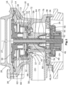
Figur 1 zeigt eine Seitenansicht einer erfindungsgemäßen Ventilvorrichtung in geschnittener Darstellung. -
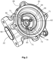
Figur 2 zeigt eine perspektivische Darstellung des Gehäuses der Ventilvorrichtung gemäßFigur 1 .
-
figure 1 shows a side view of a valve device according to the invention in a sectional representation. -
figure 2 shows a perspective view of the housing of the valve device according to FIGfigure 1 .
Die erfindungsgemäße Ventilvorrichtung besteht aus einem pneumatisch betätigbaren Aktor 10 mit einem Aktorraum 11, in dem eine Steuerkammer 12 ausgebildet ist, in welche ein Unterdruck über einen Anschlussstutzen 14 beispielsweise aus einer Vakuumpumpe über eine elektrisches Umschaltventil eingeleitet werden kann, der auf eine erste Membran 16 wirkt, welche durch den Unterdruck entgegen einer Federkraft einer ersten Feder 18 verformt wird. Der Aktorraum 11 wird durch ein Gehäuse 20 begrenzt, welches auch eine Auflagefläche für die erste Feder 18 aufweist und gleichzeitig ein Strömungsgehäuse der Ventilvorrichtung bildet, welches einen Einlass 22 und einen Auslass 24 aufweist. Aktorseitig wird das Gehäuse 20 durch einen Deckel 26 verschlossen, wobei zwischen dem Deckel 26 und einem ringförmigen Rand 28 des Gehäuses 20 die erste Membran 16 an ihrem Außenumfang eingeklemmt ist.The valve device according to the invention consists of a pneumatically actuated
Im Deckel 26 ist eine Öffnung 27 ausgebildet, so dass in dem Bereich des Aktorraums 11 zwischen dem Deckel 26 und der ersten Membran 16 Atmosphärendruck herrscht. Der Innenumfang der Membran 16 ist an einen Ventilstangenträger 30 angespritzt, an welchem eine Ventilstange 32 befestigt ist und der als zweite Auflagefläche für das entgegengesetzte Ende der ersten Feder 18 dient, über welche die Ventilstange 32 in Richtung des Deckels 26 belastet ist.An
Am zum Aktor 10 entgegengesetzten Ende der Ventilstange 32 ist ein Ventilschließglied 34 befestigt, welches mit einem ersten Ventilsitz 36 zusammenwirkt, der an einer Ventilplatte 38 ausgebildet ist, welche im Gehäuse 20 befestigt ist und Durchströmungsquerschnitte 40 aufweist, über die der Einlass 22 mit dem Auslass 24 durch Abheben des Ventilschließgliedes 34 vom Ventilsitz 36 verbindbar ist. An der Ventilplatte 38 ist zusätzlich ein konzentrisch innerhalb des ersten Ventilsitzes 36 angeordneter zweiter Ventilsitz 42 ausgebildet, der mit einer als Rückschlagventil wirkenden Rückschlagplatte 44 korrespondiert, welche über ein Federelement 46 in Richtung des zweiten Ventilsitzes 42 belastet wird und auf der Ventilstange 32 gelagert ist. Dieses Federelement 46 stützt sich mit seinem gegenüberliegenden axialen Ende am Ventilschließglied 34 ab und ist radial ebenso wie die Rückschlagplatte 44 im den Durchströmungsquerschnitt 40 verschließenden Zustand des Ventilschließgliedes 34 von diesem umgeben.A
Die Rückschlagplatte 44 wird entsprechend bei geschlossenem Ventilschließglied 34 und damit in Normalstellung des Aktors 10, in der kein Vakuum in der Steuerkammer 12 anliegt, durch das Federelement 46 gegen den zweiten Ventilsitz 42 belastet. Da dies insbesondere der Fall ist, wenn sich die Ventilvorrichtung im abgeschalteten Zustand des Verbrennungsmotors befindet, können durch Verunreinigungen aus dem Abgas oder durch gefrierende Flüssigkeiten Anhaftungen zwischen dem zweiten Ventilsitz 42 und der Rückschlagplatte 44 entstehen, die eine korrekte Funktionsweise des Rückschlagventils bei einem anschließenden Start des Verbrennungsmotors verhindern.The
Aus diesem Grund wird ein pneumatisch betätigbares Abstandselement 48 im Gehäuse 20 zusätzlich montiert, dessen axiales Ende bei abgeschaltetem Ventil beziehungsweise bei geschlossenem Ventilschließglied 34 gegen die Rückschlagplatte 44 anliegt und diese vom zweiten Ventilsitz 42 entfernt, so dass ein Spalt 50 zwischen dem zweiten Ventilsitz 42 und der Rückschlagplatte 44 gebildet wird.For this reason, a pneumatically actuable spacer element 48 is also installed in
Das Abstandselement 48 besteht aus einem ringförmigen Trägerelement 52, von dem aus sich drei Arme 54 einander gegenüberliegend durch drei Öffnungen 55, die sich von einer Grundfläche 58 aus dem Aktorraum 11 und durch das Gehäuse 20 in Richtung der Rückschlagplatte 44 erstrecken. Es könnten auch beispielsweise zwei oder mehr als drei Arme 54 ausgebildet werden, welche üblicherweise gleichmäßig über den Umfang verteilt werden. Das ringförmige Trägerelement 52 ist an einer zweiten Membran 56 befestigt, welche die Steuerkammer 12 in Richtung des Ventilschließgliedes 34 radial innerhalb der ersten Feder 18 begrenzt und somit die Steuerkammer 12 als ersten Teilraum von einem zweiten Teilraum 57 des Aktorraums 11 trennt, der somit zwischen der Grundfläche 58 des Gehäuses 20 und der zweiten Membran 56 ausgebildet wird. Diese zweite Membran 56 ist an ihrem Außenumfang zwischen der Grundfläche 58 des Gehäuses 20 und einem Befestigungsring 60 eingeklemmt, der in einen entsprechenden sich in die Steuerkammer 12 erstreckende ringförmige Erhebung 62 des Gehäuses 20, welcher von der ersten Feder 18 umgeben ist und sich von der Grundfläche 58 in Richtung der ersten Membran 16 erstreckt, eingepresst ist und die zweite Membran 56 entsprechend nach radial außen umgibt. Am Innenumfang ist die zweite Membran 56 axial zwischen der Grundfläche 58 des Gehäuses 20, in dem auch eine Aufnahmebohrung 64 zur Aufnahme einer Gleitbuchse 66, in der die Ventilstange 32 geführt wird, und einem nach radial außen stehenden Kragen 68 dieser Gleitbuchse 66, der als Befestigungselement dient, eingeklemmt.The spacer element 48 consists of an
In der Steuerkammer 12 ist eine zweite Feder 70 angeordnet, die sich einerseits an der zweiten Membran 56 beziehungsweise dem Trägerelement 52 abstützt und an der entgegengesetzten Seite gegen den Ventilstangenträger 30 anliegt. Diese zweite Feder 70 weist eine größere Federkraft als das auf die Rückschlagplatte 44 wirkende Federelement 46 auf, wodurch sichergestellt wird, dass bei Betätigung der zweiten Membran 56 durch die zweite Feder 70 die Rückschlagplatte 44 vom Ventilsitz 42 abgehoben wird und nicht auf diesen aufgepresst wird. Wird ein Vakuum in der Steuerkammer 12 gezogen, wird entsprechend einerseits die Ventilstange 32 derart bewegt, dass das Ventilschließglied 34 vom ersten Ventilsitz 36 abgehoben wird und andererseits das Abstandselement 48 in entgegengesetzter Richtung gezogen, wodurch die Rückschlagplatte 44 durch das Federelement 46 auf den Ventilsitz 42 gedrückt wird und gegen diesen anliegt, solange nicht die durch den geförderten Luftstrom entstehende Luftdruck eine Kraft auf die Rückschlagplatte 44 ausübt, welche die Kraft des Federelementes 46 übersteigt.A
Die Anordnung der zweiten Membran 56 sorgt gleichzeitig dafür, dass keine Kondensate oder Verschmutzungen enthaltende Dämpfe in die Steuerkammer 12 eindringen können. Allerdings können solche Dämpfe und Kondensate in den zweiten Teilraum 57 zwischen der Grundfläche 58 und der zweiten Membran 56 eindringen. Dies kann bei bekannten Ventilen dieser Bauform dazu führen, dass sich insbesondere im abgeschalteten Zustand der Verbrennungskraftmaschine Verklebungen zwischen der Membran 56 und der Grundfläche 58 bilden, da in diesem Zustand die Arme 54 gegen die Rückschlagplatte 44 anliegen und die zweite Membran 56 auf der Grundfläche 58 aufliegt.At the same time, the arrangement of the
Die Verklebungen entstehen dabei entweder durch Verdampfung der Kondensate und daraus folgender Ablagerung der Verschmutzungen oder bei Minustemperaturen durch Gefrieren der Kondensate und daraus folgender Eisbildung zwischen der Membran 56 und der Grundfläche 58.The sticking occurs either as a result of evaporation of the condensate and the consequent deposit of dirt or, at sub-zero temperatures, as a result of the condensate freezing and the consequent formation of ice between the
Um dies zu verhindern, sind um die Öffnungen 55 herum schmale Vorsprünge 71 ausgebildet, die sich von der Grundfläche 58 axial in Richtung der zweiten Membran 56 erstrecken und zwar in einen geodätisch oberhalb der Grundfläche 58 angeordneten Bereich. Dies bedeutet, dass die obere begrenzende Fläche der Vorsprünge 71 einen größeren Abstand zum Erdmittelpunkt aufweist als die Grundfläche 58. Dies hat zur Folge, dass sich auf den Vorsprüngen 71 kein Kondensat oder dergleichen absetzen und verdampfen oder frieren kann, da dieses der Schwerkraft folgend zuvor zur Grundfläche 58 abströmt.In order to prevent this,
Zusätzlich ist in der Grundfläche 58 ein Ablauf 72 ausgebildet, der sich von der Grundfläche 58 durch das Gehäuse zum Einlass 22 der Ventilvorrichtung erstreckt. Dieser Ablauf 72 ist als Kanal ausgeformt, dessen begrenzende Wände 74 zum Einlass 22 abfallend ausgebildet sind. Dies bedeutet, dass der Ursprung des Ablaufs 72 im eingebauten Zustand der Ventilvorrichtung an einer geodätisch im Vergleich zur übrigen Grundfläche 58 niedrigsten Position ausgebildet ist und sich der Einlass 22 geodätisch unterhalb des Ablaufs 72 befindet, so dass anfallendes Kondensat mit den darin gelösten Verschmutzungen immer aus dem Teilraum 57 von den Vorsprüngen 71 über den Ablauf 72 und zum Einlass 22 abgeführt wird. Entsprechend werden Verklebungen der Membran 56 zuverlässig verhindert.Additionally, a
Verschmutzungen könnten auch direkt entlang der Ventilstange 32 und zwar zwischen dieser und der Gleitbuchse 66 direkt in den Steuerkammer 12 gelangen, was jedoch dadurch verhindert wird, dass sich von einem innerer Gehäuseabschnitt 76 in Richtung der Ventilplatte 38 erstreckt, der kurz vor der Ventilplatte 38 endet und zwischen dessen Ende und der Ventilplatte 38 der Außenumfang einer dritten Membran 78 eingeklemmt ist, deren Innenumfang an der Ventilstange 32 dichtend befestigt ist. Entsprechend wird der Führungsbereich der Ventilstange 32 durch die zweite Membran 56 und die dritte Membran 78 vollständig abgedichtet.Contamination could also reach the
Soll im Betrieb beispielsweise ein Sekundärluftstrom in den Abgasbereich des Verbrennungsmotors eingeleitet werden, wird in der Steuerkammer 12 ein Vakuum gezogen. Die erste Membran 16 und die zweite Membran 56 werden zueinander ausgelenkt, so dass das Ventilschließglied 34 vom ersten Ventilsitz 36 abgehoben wird und das Abstandselement 48 von der Rückschlagplatte 44 entfernt wird. In diesem Betriebszustand nimmt die Rückschlagplatte 44 ihre normale Funktion als Rückschlagventil auf und Luft kann vom Einlass 22 zum Auslass 24 strömen, während der umgekehrte Weg durch die Rückschlagplatte 44 gesperrt wird. Soll keine Luft mehr gefördert werden oder wird der Verbrennungsmotor im Folgenden ausgestellt, gelangt Luft in die Steuerkammer 12, so dass die Federkräfte die Stellung der Ventilstange 32 und des Abstandselementes 48 bestimmen. Dies hat zur Folge, dass das Ventilschließglied 34 gegen seinen Ventilsitz 36 bewegt wird und diesen verschließt und das Abstandselement 48 gegen die Rückschlagplatte 44 gedrückt wird und diese vom Ventilsitz 42 entfernt. Gleichzeitig wird die Membran 56 gegen die Vorsprünge 71 gedrückt. Hierdurch können die am Auslass 24 vorhandenen Abgase und die im Abgas vorhandenen Schmutzstoffe sowie anfallende Kondensate sich weder im Anschlagbereich der Rückschlagplatte 44 am zweiten Ventilsitz 42 anlagern noch an der Auflage der Membran 56 auf der Grundfläche 58 , da das Kondensat aus diesem Bereich zuvor über den Ablauf 72 abgeführt wird. Entsprechend wird die Funktionsfähigkeit der Abstandselemente über einen langen Zeitraum zuverlässig aufrecht erhalten.If, for example, a secondary air flow is to be introduced into the exhaust gas area of the internal combustion engine during operation, a vacuum is drawn in the
Es sollte deutlich sein, dass der Schutzbereich des vorliegenden Hauptanspruchs nicht auf das beschriebene Ausführungsbeispiel beschränkt ist. So können die Vorsprünge selbstverständlich bei einem anderen Aufbau des Ventils auch an einer zur mit der Ventilstange verbundenen Membran gegenüberliegenden Grundfläche ausgebildet werden, so dass deren Funktionsfähigkeit sichergestellt wird. In diesem Fall ist beispielsweise nur eine Membran im Aktorraum, wobei der untere Teilraum mit dem Einlass verbunden ist und durch die Grundfläche mit den Vorsprüngen begrenzt ist, während der obere Teilraum als Steuerraum dient. Selbstverständlich sind auch Änderungen bezüglich des Aufbaus der verschiedenen Teile der Ventilvorrichtung wie dem Gehäuse, dem Abstandselement oder der Befestigungselemente denkbar.It should be clear that the scope of protection of the present main claim is not limited to the described embodiment. With a different construction of the valve, the projections can of course also be formed on a base surface opposite to the membrane connected to the valve rod, so that its functionality is ensured. In this case, for example, there is only one membrane in the actuator chamber, with the lower partial chamber being connected to the inlet and being delimited by the base area with the projections, while the upper partial chamber serves as a control chamber. Of course, changes to the structure of the various parts of the valve device, such as the housing, the spacer element or the fastening elements, are also conceivable.
Claims (12)
- Valve device for an internal combustion engine comprisinga housing (20) with an inlet (22) and an outlet (24),a valve closure member (34) which can be lowered onto a valve seat (36) and lifted off the valve seat (36)a pneumatically actuated actuator (10), via which the valve closing member (34) is movable, and which comprises at least one diaphragm (16; 56) which is clamped in the housing (20) and divides an actuator space (11) into a first partial space (12) and a second partial space (57),characterized in thatat least one projection (71) is formed on a base surface (58) of the housing (20), which projection rises axially from the base surface (58) in the direction of the diaphragm (16; 56) and on which the diaphragm (16; 56) rests in at least one of its end positions on the housing (20),wherein a drain (72) is configured in the base surface (58), via which a fluidic connection exists between the second partial space (57) and the inlet (22) or the outlet (24).
- Valve device for an internal combustion engine according to claim 1,
characterized in that
the second partial space (57) is delimited by the diaphragm (56) and a base surface (58) of the housing (20) opposite the diaphragm (56). - Valve device for an internal combustion engine according to claim 1 or 2,
characterized in that
the drain (72) extends from a geodetically lowest position of the base surface (58) in the direction of the inlet (22) or the outlet (24) and a wall (74) delimiting the drain (72) is configured to slope towards the inlet (22) or the outlet (24). - Valve device for an internal combustion engine according to one of the preceding claims,
characterized in that
the at least one projection (71) extends from the base surface (58) to a position geodetically above the base surface (58). - Valve device for an internal combustion engine according to one of the preceding claims,
characterized in that
a plurality of projections (71) extend from the base surface (58) in the direction of the diaphragm (56), which are uniformly distributed over the circumference of the base surface (58). - Valve device for an internal combustion engine according to one of the preceding claims,
characterized in that
the valve device comprises a valve rod (32) via which the diaphragm (16) is connected to the valve closure member (34). - Valve device for an internal combustion engine according to any one of claims 1 to 5,
characterized in that
the valve device comprises a check plate (44) which is loaded via a spring force in the direction of a second valve seat (42) and comprises a through-flow cross-section (40) between the inlet (22) and the outlet (24) which can be opened or closed by the valve closing member (34) and the check plate (44) and comprises at least one pneumatically actuable spacer element (48) by means of which the check plate (44) is lifted from the second valve seat (42) against the spring force when the valve closing member (34) rests on the first valve seat (36), wherein the spacer element (48) is connected to the diaphragm (56) which rests on the projections (71) in at least one of its end positions on the housing (20). - Valve device for an internal combustion engine according to claim 7,
characterized in that
the spacer element (48) projects through an opening (55) in the base surface (58), which is radially delimited on the side facing the diaphragm (56) by the projection (71) rising axially in the direction of the diaphragm (56). - Valve device for an internal combustion engine according to claim 7 or 8,
characterized in that
the valve device comprises a first diaphragm (16) which is connected to the valve rod (32) and comprises a second diaphragm (56) which is connected to the at least one spacer element (48) and which, in at least one of its end positions on the housing (20), rests on the projections (71), wherein the first diaphragm (16) and the second diaphragm (56) delimit a control chamber (12) of the pneumatic actuator (10) which defines the first partial space. - Valve device for an internal combustion engine according to any one of claims 7 to 9,
characterized in that
the spacer element (48) comprises at least one arm (54) movable against the check plate (44). - Valve device for an internal combustion engine according to one of claims 9 or 10,
characterized in that
the second diaphragm (56) is clamped at its inner circumference and at its outer circumference between the housing (20) and a fastening element (60, 70). - Valve device for an internal combustion engine according to one of claims 10 or 11,
characterized in that
three arms (54) are arranged offset from one another by 120°, which project through three openings (55) in the base surface (58), which are respectively delimited radially on the side facing the diaphragm (56) by the projections (71) rising axially in the direction of the diaphragm (56).
Applications Claiming Priority (1)
| Application Number | Priority Date | Filing Date | Title |
|---|---|---|---|
| PCT/EP2019/067025 WO2020259823A1 (en) | 2019-06-26 | 2019-06-26 | Valve device for an internal combustion engine |
Publications (2)
| Publication Number | Publication Date |
|---|---|
| EP3990761A1 EP3990761A1 (en) | 2022-05-04 |
| EP3990761B1 true EP3990761B1 (en) | 2023-05-31 |
Family
ID=67139711
Family Applications (1)
| Application Number | Title | Priority Date | Filing Date |
|---|---|---|---|
| EP19735255.2A Active EP3990761B1 (en) | 2019-06-26 | 2019-06-26 | Valve device for an internal combustion engine |
Country Status (2)
| Country | Link |
|---|---|
| EP (1) | EP3990761B1 (en) |
| WO (1) | WO2020259823A1 (en) |
Citations (2)
| Publication number | Priority date | Publication date | Assignee | Title |
|---|---|---|---|---|
| DE102008024035B4 (en) * | 2008-05-16 | 2012-01-12 | Pierburg Gmbh | Secondary air valve for internal combustion engines |
| DE10148384B4 (en) * | 2001-09-29 | 2016-01-07 | Pierburg Gmbh | Secondary air valve |
Family Cites Families (7)
| Publication number | Priority date | Publication date | Assignee | Title |
|---|---|---|---|---|
| DE10202031B4 (en) * | 2002-01-18 | 2013-05-08 | Pierburg Gmbh | Method and device for enhancing the tightness of a valve seat of a secondary air valve of a Sekundärluftzuführeinheit |
| DE10225161A1 (en) * | 2002-06-06 | 2003-12-18 | Pierburg Gmbh | valve device |
| DE10312925B3 (en) * | 2003-03-22 | 2004-11-04 | Pierburg Gmbh | Secondary air valve device |
| DE102006021467A1 (en) | 2006-05-09 | 2007-11-22 | Pierburg Gmbh | Motor vehicle valve e.g. non-return valve, has valve seat arranged between inlet and outlet, and distance unit that lies against valve body in closed position in order to maintain valve body in distance to valve seat |
| DE102006024728A1 (en) * | 2006-05-26 | 2007-11-29 | Pierburg Gmbh | Automotive valve |
| DE102007031957A1 (en) * | 2007-07-10 | 2009-01-22 | Pierburg Gmbh | Combined non-return and control valve |
| DE102016103549B3 (en) | 2016-02-29 | 2017-03-02 | Pierburg Gmbh | Valve device for an internal combustion engine |
-
2019
- 2019-06-26 EP EP19735255.2A patent/EP3990761B1/en active Active
- 2019-06-26 WO PCT/EP2019/067025 patent/WO2020259823A1/en unknown
Patent Citations (2)
| Publication number | Priority date | Publication date | Assignee | Title |
|---|---|---|---|---|
| DE10148384B4 (en) * | 2001-09-29 | 2016-01-07 | Pierburg Gmbh | Secondary air valve |
| DE102008024035B4 (en) * | 2008-05-16 | 2012-01-12 | Pierburg Gmbh | Secondary air valve for internal combustion engines |
Also Published As
| Publication number | Publication date |
|---|---|
| EP3990761A1 (en) | 2022-05-04 |
| WO2020259823A1 (en) | 2020-12-30 |
Similar Documents
| Publication | Publication Date | Title |
|---|---|---|
| DE4022129C2 (en) | ||
| EP2291717B1 (en) | Pressure control valve | |
| EP3562769B1 (en) | Suction device | |
| DE102016005357A1 (en) | Filter element, oil separator and method of controlling the pressure prevailing in a crankcase [housing] ventilation system | |
| DE102008050252B4 (en) | Valve device for internal combustion engines, in particular secondary air valve | |
| DE60204921T2 (en) | Gas control valve | |
| DE19722824A1 (en) | Fuel leakage prevention valve | |
| EP2005002B1 (en) | Screw compressor comprising a relief valve | |
| DE102016103549B3 (en) | Valve device for an internal combustion engine | |
| EP1210165B1 (en) | Filter with a valve combination component | |
| EP3990761B1 (en) | Valve device for an internal combustion engine | |
| EP3556621B1 (en) | Pressure limitation valve | |
| EP1688637A1 (en) | Gas spring | |
| DE102010004778B4 (en) | Valve for controlling a fluid flow | |
| DE102019116509B4 (en) | Valve device for an internal combustion engine | |
| EP0802470A1 (en) | Pressure regulating valve | |
| EP1072784B1 (en) | Exhaust gas recirculation valve | |
| DE19912249C2 (en) | Valve for a milk line | |
| DE102007002899A1 (en) | Valve arrangement for motor vehicle, has non-return valve releasing passage from inlet chamber to outlet chamber during minimum excess pressure, and pressure regulating valve blocking another passage from outlet chamber to inlet chamber | |
| WO2019120757A1 (en) | Filter system with non-return valve and filter element | |
| DE102013214968A1 (en) | Valve for a return part of a fuel injection system | |
| DE102009006381B4 (en) | Pressure control valve for a crankcase ventilation | |
| DE202009002743U1 (en) | Residual pressure holding valve | |
| WO2022008206A1 (en) | Valve device for an internal combustion engine | |
| DE102007054486A1 (en) | Valve i.e. inlet valve or outlet valve, for use in venting system for single or multi cylinder diesel engine, has valve body compressed during mixing of preset minimum quantity of certain fluid to gaseous medium in locking position |
Legal Events
| Date | Code | Title | Description |
|---|---|---|---|
| STAA | Information on the status of an ep patent application or granted ep patent |
Free format text: STATUS: UNKNOWN |
|
| STAA | Information on the status of an ep patent application or granted ep patent |
Free format text: STATUS: THE INTERNATIONAL PUBLICATION HAS BEEN MADE |
|
| PUAI | Public reference made under article 153(3) epc to a published international application that has entered the european phase |
Free format text: ORIGINAL CODE: 0009012 |
|
| STAA | Information on the status of an ep patent application or granted ep patent |
Free format text: STATUS: REQUEST FOR EXAMINATION WAS MADE |
|
| 17P | Request for examination filed |
Effective date: 20220105 |
|
| AK | Designated contracting states |
Kind code of ref document: A1 Designated state(s): AL AT BE BG CH CY CZ DE DK EE ES FI FR GB GR HR HU IE IS IT LI LT LU LV MC MK MT NL NO PL PT RO RS SE SI SK SM TR |
|
| REG | Reference to a national code |
Ref country code: DE Ref legal event code: R079 Ref document number: 502019007815 Country of ref document: DE Free format text: PREVIOUS MAIN CLASS: F01N0003220000 Ipc: F16K0015180000 |
|
| DAV | Request for validation of the european patent (deleted) | ||
| DAX | Request for extension of the european patent (deleted) | ||
| RIC1 | Information provided on ipc code assigned before grant |
Ipc: F01N 3/30 20060101ALI20220928BHEP Ipc: F16K 31/126 20060101ALI20220928BHEP Ipc: F02M 26/55 20160101ALI20220928BHEP Ipc: F02M 23/09 20060101ALI20220928BHEP Ipc: F02M 23/00 20060101ALI20220928BHEP Ipc: F01N 3/22 20060101ALI20220928BHEP Ipc: F16K 15/18 20060101AFI20220928BHEP |
|
| GRAP | Despatch of communication of intention to grant a patent |
Free format text: ORIGINAL CODE: EPIDOSNIGR1 |
|
| STAA | Information on the status of an ep patent application or granted ep patent |
Free format text: STATUS: GRANT OF PATENT IS INTENDED |
|
| INTG | Intention to grant announced |
Effective date: 20221215 |
|
| GRAS | Grant fee paid |
Free format text: ORIGINAL CODE: EPIDOSNIGR3 |
|
| GRAA | (expected) grant |
Free format text: ORIGINAL CODE: 0009210 |
|
| STAA | Information on the status of an ep patent application or granted ep patent |
Free format text: STATUS: THE PATENT HAS BEEN GRANTED |
|
| AK | Designated contracting states |
Kind code of ref document: B1 Designated state(s): AL AT BE BG CH CY CZ DE DK EE ES FI FR GB GR HR HU IE IS IT LI LT LU LV MC MK MT NL NO PL PT RO RS SE SI SK SM TR |
|
| REG | Reference to a national code |
Ref country code: GB Ref legal event code: FG4D Free format text: NOT ENGLISH Ref country code: CH Ref legal event code: EP |
|
| REG | Reference to a national code |
Ref country code: DE Ref legal event code: R096 Ref document number: 502019007815 Country of ref document: DE |
|
| REG | Reference to a national code |
Ref country code: AT Ref legal event code: REF Ref document number: 1571103 Country of ref document: AT Kind code of ref document: T Effective date: 20230615 |
|
| REG | Reference to a national code |
Ref country code: IE Ref legal event code: FG4D Free format text: LANGUAGE OF EP DOCUMENT: GERMAN |
|
| REG | Reference to a national code |
Ref country code: LT Ref legal event code: MG9D |
|
| REG | Reference to a national code |
Ref country code: NL Ref legal event code: MP Effective date: 20230531 |
|
| PG25 | Lapsed in a contracting state [announced via postgrant information from national office to epo] |
Ref country code: SE Free format text: LAPSE BECAUSE OF FAILURE TO SUBMIT A TRANSLATION OF THE DESCRIPTION OR TO PAY THE FEE WITHIN THE PRESCRIBED TIME-LIMIT Effective date: 20230531 Ref country code: NO Free format text: LAPSE BECAUSE OF FAILURE TO SUBMIT A TRANSLATION OF THE DESCRIPTION OR TO PAY THE FEE WITHIN THE PRESCRIBED TIME-LIMIT Effective date: 20230831 Ref country code: ES Free format text: LAPSE BECAUSE OF FAILURE TO SUBMIT A TRANSLATION OF THE DESCRIPTION OR TO PAY THE FEE WITHIN THE PRESCRIBED TIME-LIMIT Effective date: 20230531 |
|
| PG25 | Lapsed in a contracting state [announced via postgrant information from national office to epo] |
Ref country code: RS Free format text: LAPSE BECAUSE OF FAILURE TO SUBMIT A TRANSLATION OF THE DESCRIPTION OR TO PAY THE FEE WITHIN THE PRESCRIBED TIME-LIMIT Effective date: 20230531 Ref country code: PL Free format text: LAPSE BECAUSE OF FAILURE TO SUBMIT A TRANSLATION OF THE DESCRIPTION OR TO PAY THE FEE WITHIN THE PRESCRIBED TIME-LIMIT Effective date: 20230531 Ref country code: NL Free format text: LAPSE BECAUSE OF FAILURE TO SUBMIT A TRANSLATION OF THE DESCRIPTION OR TO PAY THE FEE WITHIN THE PRESCRIBED TIME-LIMIT Effective date: 20230531 Ref country code: LV Free format text: LAPSE BECAUSE OF FAILURE TO SUBMIT A TRANSLATION OF THE DESCRIPTION OR TO PAY THE FEE WITHIN THE PRESCRIBED TIME-LIMIT Effective date: 20230531 Ref country code: LT Free format text: LAPSE BECAUSE OF FAILURE TO SUBMIT A TRANSLATION OF THE DESCRIPTION OR TO PAY THE FEE WITHIN THE PRESCRIBED TIME-LIMIT Effective date: 20230531 Ref country code: IS Free format text: LAPSE BECAUSE OF FAILURE TO SUBMIT A TRANSLATION OF THE DESCRIPTION OR TO PAY THE FEE WITHIN THE PRESCRIBED TIME-LIMIT Effective date: 20230930 Ref country code: HR Free format text: LAPSE BECAUSE OF FAILURE TO SUBMIT A TRANSLATION OF THE DESCRIPTION OR TO PAY THE FEE WITHIN THE PRESCRIBED TIME-LIMIT Effective date: 20230531 Ref country code: GR Free format text: LAPSE BECAUSE OF FAILURE TO SUBMIT A TRANSLATION OF THE DESCRIPTION OR TO PAY THE FEE WITHIN THE PRESCRIBED TIME-LIMIT Effective date: 20230901 |
|
| PGFP | Annual fee paid to national office [announced via postgrant information from national office to epo] |
Ref country code: DE Payment date: 20230720 Year of fee payment: 5 |
|
| PG25 | Lapsed in a contracting state [announced via postgrant information from national office to epo] |
Ref country code: FI Free format text: LAPSE BECAUSE OF FAILURE TO SUBMIT A TRANSLATION OF THE DESCRIPTION OR TO PAY THE FEE WITHIN THE PRESCRIBED TIME-LIMIT Effective date: 20230531 |
|
| PG25 | Lapsed in a contracting state [announced via postgrant information from national office to epo] |
Ref country code: SK Free format text: LAPSE BECAUSE OF FAILURE TO SUBMIT A TRANSLATION OF THE DESCRIPTION OR TO PAY THE FEE WITHIN THE PRESCRIBED TIME-LIMIT Effective date: 20230531 |
|
| PG25 | Lapsed in a contracting state [announced via postgrant information from national office to epo] |
Ref country code: SM Free format text: LAPSE BECAUSE OF FAILURE TO SUBMIT A TRANSLATION OF THE DESCRIPTION OR TO PAY THE FEE WITHIN THE PRESCRIBED TIME-LIMIT Effective date: 20230531 Ref country code: SK Free format text: LAPSE BECAUSE OF FAILURE TO SUBMIT A TRANSLATION OF THE DESCRIPTION OR TO PAY THE FEE WITHIN THE PRESCRIBED TIME-LIMIT Effective date: 20230531 Ref country code: RO Free format text: LAPSE BECAUSE OF FAILURE TO SUBMIT A TRANSLATION OF THE DESCRIPTION OR TO PAY THE FEE WITHIN THE PRESCRIBED TIME-LIMIT Effective date: 20230531 Ref country code: PT Free format text: LAPSE BECAUSE OF FAILURE TO SUBMIT A TRANSLATION OF THE DESCRIPTION OR TO PAY THE FEE WITHIN THE PRESCRIBED TIME-LIMIT Effective date: 20231002 Ref country code: EE Free format text: LAPSE BECAUSE OF FAILURE TO SUBMIT A TRANSLATION OF THE DESCRIPTION OR TO PAY THE FEE WITHIN THE PRESCRIBED TIME-LIMIT Effective date: 20230531 Ref country code: DK Free format text: LAPSE BECAUSE OF FAILURE TO SUBMIT A TRANSLATION OF THE DESCRIPTION OR TO PAY THE FEE WITHIN THE PRESCRIBED TIME-LIMIT Effective date: 20230531 Ref country code: CZ Free format text: LAPSE BECAUSE OF FAILURE TO SUBMIT A TRANSLATION OF THE DESCRIPTION OR TO PAY THE FEE WITHIN THE PRESCRIBED TIME-LIMIT Effective date: 20230531 |
|
| REG | Reference to a national code |
Ref country code: CH Ref legal event code: PL |
|
| REG | Reference to a national code |
Ref country code: BE Ref legal event code: MM Effective date: 20230630 |
|
| PG25 | Lapsed in a contracting state [announced via postgrant information from national office to epo] |
Ref country code: MC Free format text: LAPSE BECAUSE OF FAILURE TO SUBMIT A TRANSLATION OF THE DESCRIPTION OR TO PAY THE FEE WITHIN THE PRESCRIBED TIME-LIMIT Effective date: 20230531 |
|
| PG25 | Lapsed in a contracting state [announced via postgrant information from national office to epo] |
Ref country code: MC Free format text: LAPSE BECAUSE OF FAILURE TO SUBMIT A TRANSLATION OF THE DESCRIPTION OR TO PAY THE FEE WITHIN THE PRESCRIBED TIME-LIMIT Effective date: 20230531 |
|
| PG25 | Lapsed in a contracting state [announced via postgrant information from national office to epo] |
Ref country code: LU Free format text: LAPSE BECAUSE OF NON-PAYMENT OF DUE FEES Effective date: 20230626 |
|
| REG | Reference to a national code |
Ref country code: DE Ref legal event code: R097 Ref document number: 502019007815 Country of ref document: DE |
|
| REG | Reference to a national code |
Ref country code: IE Ref legal event code: MM4A |
|
| PG25 | Lapsed in a contracting state [announced via postgrant information from national office to epo] |
Ref country code: LU Free format text: LAPSE BECAUSE OF NON-PAYMENT OF DUE FEES Effective date: 20230626 |
|
| PLBE | No opposition filed within time limit |
Free format text: ORIGINAL CODE: 0009261 |
|
| STAA | Information on the status of an ep patent application or granted ep patent |
Free format text: STATUS: NO OPPOSITION FILED WITHIN TIME LIMIT |
|
| PG25 | Lapsed in a contracting state [announced via postgrant information from national office to epo] |
Ref country code: IE Free format text: LAPSE BECAUSE OF NON-PAYMENT OF DUE FEES Effective date: 20230626 |