EP3556621B1 - Pressure limitation valve - Google Patents
Pressure limitation valve Download PDFInfo
- Publication number
- EP3556621B1 EP3556621B1 EP19164716.3A EP19164716A EP3556621B1 EP 3556621 B1 EP3556621 B1 EP 3556621B1 EP 19164716 A EP19164716 A EP 19164716A EP 3556621 B1 EP3556621 B1 EP 3556621B1
- Authority
- EP
- European Patent Office
- Prior art keywords
- housing
- piston
- pressure
- switching
- spring
- Prior art date
- Legal status (The legal status is an assumption and is not a legal conclusion. Google has not performed a legal analysis and makes no representation as to the accuracy of the status listed.)
- Active
Links
Images

Classifications
-
- G—PHYSICS
- G05—CONTROLLING; REGULATING
- G05D—SYSTEMS FOR CONTROLLING OR REGULATING NON-ELECTRIC VARIABLES
- G05D16/00—Control of fluid pressure
- G05D16/04—Control of fluid pressure without auxiliary power
- G05D16/10—Control of fluid pressure without auxiliary power the sensing element being a piston or plunger
- G05D16/107—Control of fluid pressure without auxiliary power the sensing element being a piston or plunger with a spring-loaded piston in combination with a spring-loaded slideable obturator that move together over range of motion during normal operation
-
- B—PERFORMING OPERATIONS; TRANSPORTING
- B60—VEHICLES IN GENERAL
- B60T—VEHICLE BRAKE CONTROL SYSTEMS OR PARTS THEREOF; BRAKE CONTROL SYSTEMS OR PARTS THEREOF, IN GENERAL; ARRANGEMENT OF BRAKING ELEMENTS ON VEHICLES IN GENERAL; PORTABLE DEVICES FOR PREVENTING UNWANTED MOVEMENT OF VEHICLES; VEHICLE MODIFICATIONS TO FACILITATE COOLING OF BRAKES
- B60T15/00—Construction arrangement, or operation of valves incorporated in power brake systems and not covered by groups B60T11/00 or B60T13/00
- B60T15/02—Application and release valves
- B60T15/36—Other control devices or valves characterised by definite functions
- B60T15/48—Other control devices or valves characterised by definite functions for filling reservoirs
- B60T15/50—Other control devices or valves characterised by definite functions for filling reservoirs with means for limiting or relieving pressure in reservoirs
Definitions
- the invention relates to a pressure limiting valve, comprising a housing, a switching piston adjustable in the housing in the direction of a longitudinal axis of the housing between a filling position, a pressure limiting position and a venting position, a switching piston actuated by the switching piston and releasing a venting channel in the venting position of the switching piston, a spring-loaded sequence valve, a switching piston switching spring loading in the direction of its filling position, an adjusting screw means for pretensioning the switching spring, and a tensioning spring pretensioning a piston of the sequence valve to rest on the switching piston.
- Pressure relief valves are used to maintain a predetermined operating pressure in a pressure medium system, for example a compressed air system of a vehicle. Accordingly, they are each arranged between a pressure medium source, which provides a pressure above the desired operating pressure, and the compressed air consumers in the compressed air system.
- a typical field of application for such pressure relief valves are compressed air systems for vehicle brake systems.
- a pressure medium source supplies a pressure medium which is fed via an inlet connection of the pressure relief valve to a connecting chamber formed in the housing. If the spring-loaded actuating piston rests against a mechanical stop of the housing in its lower actuating position, then a piston of the sequence valve is pushed away from its valve seat and a specified filling position of the pressure relief valve is reached. In this filling position, a fluid connection is released from the inlet port to the connecting chamber, which is connected to the pressure medium system or to at least one of its compressed air consumers via an outlet port on the housing.
- the switching piston acted upon by the pressure medium is moved by the piston of the sequence valve against the force of the switching spring, which is adjusted to the specified operating pressure, into a so-called pressure limiting position in which the connection between the inlet connector and the outlet connector is blocked. If the operating pressure falls below the target pressure due to the consumption of pressure medium, this connection is released again until the target pressure is reached again and so on.
- the switching piston If, for operational reasons, the operating pressure rises above the setpoint pressure, the switching piston is pushed axially further away from the mechanical stop of the housing into a venting position, in which the sequence valve controlled by the switching piston releases a flow path to a venting channel formed centrally in this, whereby the pressure drops again in the pressure medium system downstream behind the pressure limiting valve and the switching piston returns to its pressure limiting position at the mechanical stop of the housing.
- a pressure relief valve which works on the principle just described.
- the switching spring is pretensioned by means of an adjusting screw arranged adjustably in the bottom of the housing with the interposition of a transmission bell, the adjusting screw resting on the base of the bell and the switching spring being supported on an edge flange of the bell. It has been shown that as a result of the low structural rigidity of this arrangement, the spring characteristics and, as a result, the operating pressure in the system can change in an uncontrolled manner.
- the invention is based on the object of creating a pressure relief valve of the type mentioned in the preamble of claim 1, which is simpler in terms of production and assembly and therefore cheaper than known generic pressure relief valves, and in which deviations from the specified target pressure due to a lack of structural rigidity are excluded are.
- the invention is based on a pressure limiting valve, comprising a housing, a spring-loaded sequence valve that can be adjusted in the housing in the direction of a housing longitudinal axis between a filling position, a pressure limiting position and a venting position, a spring-loaded sequence valve that can be actuated by the switching piston and that releases a venting channel in the venting position of the switching piston, a switching spring loading the switching piston in the direction of its filling position, an adjusting screw means for biasing the switching spring, and a tensioning spring biasing a piston of the sequence valve to rest on the switching piston.
- the housing is designed in one piece and largely has the geometry of a tubular body open at both ends, that the pretensioning adjusting screw means as a screwable into an axial end of the housing, having a contact surface for the associated end of the switching spring Screw cap is formed, and that the tension spring is axially pretensioned by means of an insert bushing which can be inserted into the other end of the housing remote from the screw cap.
- the geometry of the housing as a tubular body open at both ends allows the switching piston with the entire system that biases it into its filling position from a first side of the housing, and the sequence valve with its system that biases it in the opposite direction from the second side of the housing to be installed, the spring preloading the switching piston
- the screw cap on the one hand and the insert bushing which prestresses the tension spring for the sequence valve on the other hand close the respectively assigned ends of the housing.
- the screw cap that clamps the switching spring in accordance with the specified operating pressure (target pressure) directly forms an axial contact surface for the switching spring without going through other components, so that the design is simplified and, due to the stable support of the switching spring on the screw cap, its reliable function is guaranteed. There is no need to screw two housing parts together, so that the assembly of the pressure relief valve is simplified.
- the insert socket is fastened in the housing by means of a bayonet lock i.
- the insertion of the insert socket into the housing is simple in this way and can be carried out in an extremely short time.
- An advantageous embodiment provides that, on the one hand, on the insert bushing and, on the other hand, on the housing, there are formed anti-rotation means that engage in the assembled state of the insert bushing. As a result, an automatic loosening of the insert bushing, for example under operating conditions associated with vibrations, is excluded.
- a further embodiment of the pressure relief valve provides that a first, radially outer pipe socket, which extends in the direction of the axial center of the housing and accommodates the tension spring, is formed on the insert sleeve. and that the piston of the sequence valve has the shape of an annular groove that is open towards the radially outer pipe socket and slipped over its axially inner end. The piston of the sequence valve or its radially outer annular groove wall is guided approximately telescopically at the axially inner end of the radially outer pipe socket of the insert socket.
- a second pipe socket is arranged radially inside the first pipe socket and concentric to this, which is open at its two axial ends and with its axially inner end a central opening in the piston of the sequence valve axially penetrated.
- the second pipe socket serves here as a ventilation channel, which means that the ventilation does not take place here via the movable piston but via the fixed insert bushing.
- the invention provides that the axially outwardly facing open end of the second, radially inner pipe socket of the insert socket is covered by an outwardly pivotable elastic valve flap which is attached to the pipe socket trained fastening means is held on this. This valve flap closes the path from the outside to the inside, but it opens during the venting process.
- the switching piston In order to enable pressure equalization between the piston sides of the switching piston, that is to say the lower side of the piston and the upper side of the piston during a piston movement, the switching piston is penetrated by a compensation opening connecting the two piston sides.
- a structural embodiment of the pressure relief valve according to the invention provides that a connecting chamber formed in the housing is in each case directly connected to the associated inlet port and outlet port formed integrally on the housing.
- the pressure-limiting valve is connected to the pressure medium source via the inlet connection by means of suitable pressure medium lines and via the outlet connection connected to the pressure medium system or to its compressed air consumer.
- a preferred embodiment of the invention provides that the insert socket is made from a plastic material.
- the insert socket is made from a plastic material.
- the screw cap consists of a plastic, which makes it light-weight and inexpensive to manufacture.
- the pressure relief valve 2 shown initially has a housing 4 in the form of a tubular body open at its two axial ends, a switching piston 8 adjustable in the housing 4 in the direction of the housing longitudinal axis 6, and a switching piston 8 which loads the switching piston 8 in the axially inward direction into the housing 4 Switching spring 12.
- the switching spring 12 is supported with its upper axial end on a contact surface 15 of a screw cap 14 which is screwed into the upper end of the housing 4 by means of a sealed screw thread 10. By screwing the screw cap 14 into the housing 4 at different depths, the axial preload of the switching spring 12 is set.
- a sequence valve 16 cooperating with the switching piston 8 is arranged in the essentially cylindrical cavity of the housing 4, the piston 17 of which is prestressed by means of a tension spring 18 in the direction of the axial center of the housing 4.
- the tension spring 18 is axially pretensioned by means of an insert bushing 20 inserted into the lower end of the housing 4.
- the insert socket 20 is preferably made of a plastic material, and it is held in the housing 4 by means of a bayonet catch 56, as will be explained in detail below.
- the switching spring 12 and the tension spring 18 are recognizable as helical compression springs with different spring force effects.
- the insert bushing 20 has a base 21 on which a first, radially outer pipe socket 22 concentric to the housing longitudinal axis 6 is formed, in the cylindrical cavity of which the tension spring 18 is received.
- the piston 17 of the sequence valve 16 has the shape of an annular groove that is open towards the radially outer pipe socket 22 and slipped over the axially inner end 26 of the outer pipe socket 22.
- the piston 17 or its radially outer annular groove wall is guided coaxially to the housing longitudinal axis 6 on the radially outer pipe socket 22 in a telescopic manner and is tilt-proof.
- a second pipe socket 24 is formed on the insert bushing 20 and is arranged radially inside the first pipe socket 22 and arranged concentrically to it, which is essentially open at its two axial ends, and the axially inner end 26 of which has a central opening in the piston 17 of the sequence valve 16 axially penetrated, so that this piston 17 is additionally guided on the radially inner pipe socket 24.
- the switching piston 8 can be positioned in a manner known per se in a filling position, not shown, resting against an axial stop 28 of the housing 4, in which the piston 17 of the sequence valve 16 is lifted from an associated axial sealing seat 30 on the housing 4, thereby creating a flow path from an inlet port 32 of the housing 4 releases via a connection chamber 34 formed in the housing 4 to an outlet port 36 of the housing 4.
- the switching piston 8 in the in Fig. 1 Be positioned in the pressure limiting position shown, in which the piston 17 of the sequence valve 16 rests axially on the sealing seat 30 of the housing 4 and blocks the flow path from the inlet connector 32 to the outlet connector 36.
- the switching piston 8 can be displaced in an upper venting position, not shown, near the screw cap, in which a central, tubular connecting piece 38 formed on the switching piston 8 radially on the inside and axially on the inside is lifted axially from the piston 17 of the sequence valve 16 and thus a flow path from the connecting chamber 34 to the vent channel 40 formed by the radially inner pipe socket 24 of the sequence valve 16.
- the radially inner pipe socket 24 of the sequence valve 16 is open to the atmosphere via its lower open end, so that compressed air can be blown off there.
- the bottom 21 of the insert bushing 20 has a central opening in the axial extension of the ventilation channel 40, over which three retaining arms 42a, 42b, 42c extend.
- the three holding arms 42a, 42b, 42c are connected to one another centrally in the opening of the bottom 21 of the insert socket 20 and there form a fastening element 44, onto which an elastic valve flap 46 is clipped by means of its central bore 47, which prevents the ingress of water and dirt prevented in the venting channel 40, but not hindered an escape of air during the venting process.
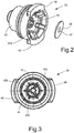
- Fig. 3 shows the insert sleeve 20 without the valve flap 46
- Fig. 2 the elastic valve flap 46 is shown close to the insert bushing 20 prior to its assembly
- Fig. 1 shows the valve flap 46 in the assembled state.
- the illustrated insert bushing 20 has at its axially lower end remote from the shift piston two radially protruding connecting flanges 48, 49, which are formed with associated inner flange segments at the lower axial end of the housing 4 50, 52 cooperate and form the bayonet lock 56 mentioned.
- To assemble the insert bushing 20 it is inserted axially into the housing 4 against the force of the tension spring 18 and then rotated about its longitudinal axis, the outer flange segments 48, 49 of the insert bushing 20 engaging behind the associated inner flange segments 50, 52 of the housing 4. When the correct rotational position is reached, the outer flange segments 48, 49 are arranged radially on the outside in a respective circular segment-shaped locking opening 51, 53 of the housing 4.
- a central compensation opening 54 connecting the two piston sides is formed, by means of which pressure equalization between the upper and lower cylinder chambers of the housing 4 is possible during a switching movement of the switching piston.
- the actuating piston 8 and the insert bushing 20 are each sealed against the housing 4 by means of a sealing ring 9, 23.
Description
Die Erfindung betrifft ein Druckbegrenzungsventil, aufweisend ein Gehäuse, einen in dem Gehäuse in Richtung einer Gehäuselängsachse zwischen einer Füllstellung, einer Druckbegrenzungsstellung und einer Entlüftungsstellung verstellbaren Schaltkolben, ein vom Schaltkolben betätigbares, bei der Entlüftungsstellung des Schaltkolbens einen Entlüftungskanal freigebendes, federbelastetes Folgeventil, eine den Schaltkolben in Richtung zu seiner Füllstellung hin belastende Schaltfeder, ein Einstellschraubmittel zum Vorspannen der Schaltfeder, und eine einen Kolben des Folgeventils zur Anlage am Schaltkolben hin vorspannende Spannfeder.The invention relates to a pressure limiting valve, comprising a housing, a switching piston adjustable in the housing in the direction of a longitudinal axis of the housing between a filling position, a pressure limiting position and a venting position, a switching piston actuated by the switching piston and releasing a venting channel in the venting position of the switching piston, a spring-loaded sequence valve, a switching piston switching spring loading in the direction of its filling position, an adjusting screw means for pretensioning the switching spring, and a tensioning spring pretensioning a piston of the sequence valve to rest on the switching piston.
Druckbegrenzungsventile dienen dazu, in einem Druckmittelsystem, beispielsweise einem Druckluftsystem eines Fahrzeugs, einen vorgegebenen Betriebsdruck aufrechtzuerhalten. Sie sind demnach jeweils zwischen einer Druckmittelquelle, die einen über dem gewünschten Betriebsdruck liegenden Druck zur Verfügung stellt, und den Druckluftverbrauchern im Druckluftsystem angeordnet. Ein typisches Anwendungsgebiet für derartige Druckbegrenzungsventile sind Druckluftsysteme für Fahrzeugbremsanlagen.Pressure relief valves are used to maintain a predetermined operating pressure in a pressure medium system, for example a compressed air system of a vehicle. Accordingly, they are each arranged between a pressure medium source, which provides a pressure above the desired operating pressure, and the compressed air consumers in the compressed air system. A typical field of application for such pressure relief valves are compressed air systems for vehicle brake systems.
Ein Beispiel des Standes der Technik nach Artikel 54(3) EPÜ ist in
Die Funktionsweise von Druckbegrenzungsventilen der genannten Art ist wie folgt: Eine Druckmittelquelle liefert ein Druckmittel, welches über einen Einlassstutzen des Druckbegrenzungsventils einer im Gehäuse ausgebildeten Verbindungskammer zugeführt wird. Wenn der federbelastete Stellkolben dabei in seiner unteren Betätigungsstellung an einen mechanischen Anschlag des Gehäuses anliegt, dann ist ein Kolben des Folgeventils von dessen Ventilsitz weggedrückt und so eine festgelegte Füllstellung des Druckbegrenzungsventils erreicht. Bei dieser Füllstellung ist eine Fluidverbindung von dem Einlassstutzen zu der Verbindungskammer freigegeben ist, welche über einen Auslassstutzen am Gehäuse mit dem Druckmittelsystem beziehungsweise mit zumindest einem seiner Druckluftverbraucher verbunden ist. Sobald der Druck in der Verbindungskammer und damit im Druckmittelsystem den vorgegebenen Betriebsdruck erreicht, wird der vom Druckmittel beaufschlagte Schaltkolben durch den Kolben des Folgeventils gegen die Kraft der auf den vorgegebenen Betriebsdruck abgestimmten Schaltfeder in eine sogenannte Druckbegrenzungsstellung verstellt, bei der die Verbindung zwischen Einlassstutzen und Auslassstutzen gesperrt ist. Wenn der Betriebsdruck infolge Druckmittelverbrauchs unter den Solldruck absinkt, wird diese Verbindung wieder freigegeben, bis der Solldruck wieder erreicht ist und so fort.The mode of operation of pressure relief valves of the type mentioned is as follows: A pressure medium source supplies a pressure medium which is fed via an inlet connection of the pressure relief valve to a connecting chamber formed in the housing. If the spring-loaded actuating piston rests against a mechanical stop of the housing in its lower actuating position, then a piston of the sequence valve is pushed away from its valve seat and a specified filling position of the pressure relief valve is reached. In this filling position, a fluid connection is released from the inlet port to the connecting chamber, which is connected to the pressure medium system or to at least one of its compressed air consumers via an outlet port on the housing. As soon as the pressure in the connecting chamber and thus the specified operating pressure is reached in the pressure medium system, the switching piston acted upon by the pressure medium is moved by the piston of the sequence valve against the force of the switching spring, which is adjusted to the specified operating pressure, into a so-called pressure limiting position in which the connection between the inlet connector and the outlet connector is blocked. If the operating pressure falls below the target pressure due to the consumption of pressure medium, this connection is released again until the target pressure is reached again and so on.
Wenn aus betrieblichen Gründen der Betriebsdruck über den Solldruck ansteigt, wird der Schaltkolben axial noch weiter von dem mechanischen Anschlag des Gehäuses weg in eine Entlüftungsstellung geschoben, bei der das vom Schaltkolben gesteuerte Folgeventil einen Strömungsweg zu einem zentral in diesem ausgebildeten Entlüftungskanal freigibt, wobei der Druck im Druckmittelsystem stromab hinter dem Druckbegrenzungsventil wieder abfällt und der Schaltkolben in seine Druckbegrenzungsstellung am mechanischen Anschlag des Gehäuses zurückkehrt.If, for operational reasons, the operating pressure rises above the setpoint pressure, the switching piston is pushed axially further away from the mechanical stop of the housing into a venting position, in which the sequence valve controlled by the switching piston releases a flow path to a venting channel formed centrally in this, whereby the pressure drops again in the pressure medium system downstream behind the pressure limiting valve and the switching piston returns to its pressure limiting position at the mechanical stop of the housing.
Aus der
Um ein solches Druckbegrenzungsventil montieren zu können, ist dessen Gehäuse in seiner Serienausführungsform gemäß dem Druckbegrenzungsventil WABCO 475 010 302 zweiteilig ausgeführt, wobei nach dem Einführen der Funktionselemente in ein erstes Gehäuseteil das zweite Gehäuseteil mit dem ersten verschraubt werden muss. Das bekannte Druckbegrenzungsventil ist deshalb herstellungs- und montagetechnisch vergleichsweise aufwendig und teuer.In order to be able to assemble such a pressure relief valve, its housing in its series version is made in two parts according to the pressure relief valve WABCO 475 010 302, whereby after the functional elements have been inserted into a first housing part, the second housing part must be screwed to the first. The known pressure relief valve is therefore comparatively complex and expensive in terms of production and assembly.
Vor diesem Hintergrund liegt der Erfindung die Aufgabe zugrunde, ein Druckbegrenzungsventil der im Oberbegriff des Anspruchs 1 genannten Art zu schaffen, welches herstellungs- sowie montagetechnisch einfacher und damit preiswerter ist als bekannte gattungsgemäße Druckbegrenzungsventile, und bei welchem Abweichungen vom vorgegebenen Solldruck infolge fehlender konstruktiver Steifigkeit ausgeschlossen sind.Against this background, the invention is based on the object of creating a pressure relief valve of the type mentioned in the preamble of claim 1, which is simpler in terms of production and assembly and therefore cheaper than known generic pressure relief valves, and in which deviations from the specified target pressure due to a lack of structural rigidity are excluded are.
Die Lösung dieser Aufgabe wird durch ein Druckbegrenzungsventil mit den Merkmalen des Anspruchs 1 erreicht, während vorteilhafte Ausgestaltungen und Weiterbildungen der Erfindung den Unteransprüchen entnehmbar sind.The solution to this problem is achieved by a pressure relief valve with the features of claim 1, while advantageous configurations and developments of the invention can be found in the subclaims.
Demnach geht die Erfindung aus von einem Druckbegrenzungsventil, aufweisend ein Gehäuse, einen in dem Gehäuse in Richtung einer Gehäuselängsachse zwischen einer Füllstellung, einer Druckbegrenzungsstellung und einer Entlüftungsstellung verstellbaren Schaltkolben, ein vom Schaltkolben betätigbares, bei der Entlüftungsstellung des Schaltkolbens einen Entlüftungskanal freigebendes, federbelastetes Folgeventil, eine den Schaltkolben in Richtung zu seiner Füllstellung hin belastende Schaltfeder, ein Einstellschraubmittel zum Vorspannen der Schaltfeder, und eine einen Kolben des Folgeventils zur Anlage am Schaltkolben hin vorspannende Spannfeder.Accordingly, the invention is based on a pressure limiting valve, comprising a housing, a spring-loaded sequence valve that can be adjusted in the housing in the direction of a housing longitudinal axis between a filling position, a pressure limiting position and a venting position, a spring-loaded sequence valve that can be actuated by the switching piston and that releases a venting channel in the venting position of the switching piston, a switching spring loading the switching piston in the direction of its filling position, an adjusting screw means for biasing the switching spring, and a tensioning spring biasing a piston of the sequence valve to rest on the switching piston.
Zur Lösung der gestellten Aufgabe ist dabei vorgesehen, dass das Gehäuse einstückig ausgebildet ist und weitgehend die Geometrie eines an beiden Enden offenen Rohrkörpers aufweist, dass das vorspannende Einstellschraubmittel als ein in ein axiales Ende des Gehäuses einschraubbarer, eine Anlagefläche für das zugeordnete Ende der Schaltfeder aufweisender Schraubdeckel ausgebildet ist, und dass die Spannfeder mittels einer in das andere, schraubdeckelferne Ende des Gehäuses einsetzbaren Einsatzbuchse axial vorgespannt ist.To solve the problem, it is provided that the housing is designed in one piece and largely has the geometry of a tubular body open at both ends, that the pretensioning adjusting screw means as a screwable into an axial end of the housing, having a contact surface for the associated end of the switching spring Screw cap is formed, and that the tension spring is axially pretensioned by means of an insert bushing which can be inserted into the other end of the housing remote from the screw cap.
Die Geometrie des Gehäuses als ein an seinen beiden Enden offener Rohrkörper ermöglicht es, den Schaltkolben mit dem gesamten, diesen in seine Füllstellung vorspannenden System von einer ersten Gehäuseseite her, und das Folgeventil mit seinem dieses in der entgegengesetzten Richtung vorspannenden System von der zweiten Gehäuseseite her einzubauen, wobei der die Schaltfeder für den Schaltkolben vorspannende Schraubdeckel einerseits und die die Spannfeder für das Folgeventil vorspannende Einsatzbuchse andererseits die jeweils zugeordneten Enden des Gehäuses verschließen.The geometry of the housing as a tubular body open at both ends allows the switching piston with the entire system that biases it into its filling position from a first side of the housing, and the sequence valve with its system that biases it in the opposite direction from the second side of the housing to be installed, the spring preloading the switching piston The screw cap on the one hand and the insert bushing which prestresses the tension spring for the sequence valve on the other hand close the respectively assigned ends of the housing.
Der die Schaltfeder jeweils entsprechend dem vorgegebenen Betriebsdruck (Solldruck) spannende Schraubdeckel bildet ohne Umweg über andere Bauelemente direkt eine axiale Anlagefläche für die Schaltfeder, so dass insoweit die Konstruktion vereinfacht und aufgrund einer stabilen Abstützung der Schaltfeder am Schraubdeckel ihre sichere Funktion gewährleistet sind. Die Notwendigkeit, zwei Gehäuseteile miteinander zu verschrauben entfällt, so dass die Montage des Druckbegrenzungsventils vereinfacht wird.The screw cap that clamps the switching spring in accordance with the specified operating pressure (target pressure) directly forms an axial contact surface for the switching spring without going through other components, so that the design is simplified and, due to the stable support of the switching spring on the screw cap, its reliable function is guaranteed. There is no need to screw two housing parts together, so that the assembly of the pressure relief valve is simplified.
Erfindungsgemäß ist die Einsatzbuchse mittels eines Bajonettverschlusses im Gehäuse befestigt i. Das Einsetzen der Einsatzbuchse in das Gehäuse ist auf diese Weise einfach und mit äußerst geringem Zeitaufwand durchführbar.According to the invention, the insert socket is fastened in the housing by means of a bayonet lock i. The insertion of the insert socket into the housing is simple in this way and can be carried out in an extremely short time.
Eine vorteilhafte Ausgestaltung sieht vor, dass einerseits an der Einsatzbuchse und andererseits an dem Gehäuse zusammenwirkende, im montierten Zustand der Einsatzbuchse einrastende Verdrehsicherungsmittel ausgebildet sind. Hierdurch ist ein selbsttätiges Lösen der Einsatzbuchse beispielsweise unter mit Erschütterungen verbundenen Betriebsbedingungen ausgeschlossen.An advantageous embodiment provides that, on the one hand, on the insert bushing and, on the other hand, on the housing, there are formed anti-rotation means that engage in the assembled state of the insert bushing. As a result, an automatic loosening of the insert bushing, for example under operating conditions associated with vibrations, is excluded.
Um eine verkantungsfreie Führung des Folgeventils bei einer Bewegung des Schaltkolbens zu gewährleisten, ist gemäß einer weiteren Ausgestaltung des Druckbegrenzungsventils vorgesehen, dass an der Einsatzbuchse ein sich in Richtung zur axialen Mitte des Gehäuses hin erstreckender, die Spannfeder aufnehmender erster, radial äußerer Rohrstutzen ausgebildet ist, und dass der Kolben des Folgeventils die Form einer zum radial äußeren Rohrstutzen hin offenen, über dessen axial inneres Ende gestülpten Ringnut hat. Der Kolben des Folgeventils beziehungsweise dessen radial äußere Ringnutwand wird dabei etwa teleskopartig am axial inneren Ende des radial äußeren Rohrstutzens der Einsatzbuchse geführt.In order to ensure tilt-free guidance of the sequence valve when the switching piston moves, a further embodiment of the pressure relief valve provides that a first, radially outer pipe socket, which extends in the direction of the axial center of the housing and accommodates the tension spring, is formed on the insert sleeve. and that the piston of the sequence valve has the shape of an annular groove that is open towards the radially outer pipe socket and slipped over its axially inner end. The piston of the sequence valve or its radially outer annular groove wall is guided approximately telescopically at the axially inner end of the radially outer pipe socket of the insert socket.
Gemäß einer anderen Weiterbildung der Erfindung ist vorgesehen, dass an der Einsatzbuchse ein radial innerhalb des ersten Rohrstutzens angeordneter und zu diesem konzentrischer zweiter Rohrstutzen angeordnet ist, welcher an seinen beiden axialen Enden offen ist und mit seinem axial inneren Ende eine zentrale Öffnung im Kolben des Folgeventils axial durchsetzt. Der zweite Rohrstutzen dient hierbei als Entlüftungskanal, das heißt, dass die Entlüftung hier nicht über den beweglichen Kolben sondern über die feststehende Einsatzbuchse erfolgt. Wenn der Schaltkolben seine Entlüftungsstellung einnimmt, gibt er das axial innere Ende dieses zweiten, radial inneren Rohrstutzens frei, welches dann mit der Verbindungskammer in Verbindung steht. Dadurch kann sich ein Überdruck in der Verbindungskammer und damit im Druckluftsystem über den an beiden Enden offenen Entlüftungskanal des inneren Rohrstutzens zur Atmosphäre hin abbauen, wie anhand eines Ausführungsbeispiels noch im Einzelnen beschrieben wird.According to another development of the invention, it is provided that a second pipe socket is arranged radially inside the first pipe socket and concentric to this, which is open at its two axial ends and with its axially inner end a central opening in the piston of the sequence valve axially penetrated. The second pipe socket serves here as a ventilation channel, which means that the ventilation does not take place here via the movable piston but via the fixed insert bushing. When the switching piston assumes its venting position, it releases the axially inner end of this second, radially inner pipe socket, which is then connected to the connecting chamber. As a result, an overpressure in the connecting chamber and thus in the compressed air system can be reduced to the atmosphere via the venting channel of the inner pipe socket which is open at both ends, as will be described in detail using an exemplary embodiment.
Um ein Eindringen von Außenluft und gegebenenfalls Verschmutzungen durch den Entlüftungskanal in das Druckbegrenzungsventil auszuschließen, ist erfindungsgemäß vorgesehen, dass das nach axial außen weisende offene Ende des zweiten, radial inneren Rohrstutzens der Einsatzbuchse durch eine nach außen aufschwenkbare elastische Ventilklappe abgedeckt ist, welche mittels am Rohrstutzen ausgebildeter Befestigungsmittel an diesem gehalten ist. Diese Ventilklappe verschließt den Weg von außen nach innen, sie öffnet jedoch beim Entlüftungsvorgang.In order to exclude the ingress of outside air and possibly contamination through the ventilation duct into the pressure relief valve, the invention provides that the axially outwardly facing open end of the second, radially inner pipe socket of the insert socket is covered by an outwardly pivotable elastic valve flap which is attached to the pipe socket trained fastening means is held on this. This valve flap closes the path from the outside to the inside, but it opens during the venting process.
Um einen Druckausgleich zwischen den Kolbenseiten des Schaltkolbens, also der Kolbenunterseite und der Kolbenoberseite bei einer Kolbenbewegung zu ermöglichen, ist der Schaltkolben von einer die beiden Kolbenseiten verbindenden Ausgleichsöffnung durchsetzt.In order to enable pressure equalization between the piston sides of the switching piston, that is to say the lower side of the piston and the upper side of the piston during a piston movement, the switching piston is penetrated by a compensation opening connecting the two piston sides.
Eine konstruktive Ausgestaltung des erfindungsgemäßen Druckbegrenzungsventils sieht vor, dass eine im Gehäuse ausgebildete Verbindungskammer jeweils direkt mit dem zugeordneten, am Gehäuse integral ausgebildeten Einlassstutzen und Auslassstutzen in Verbindung steht. Über den Einlassstutzen ist das Druckbegrenzungsventil mittels geeigneter Druckmittelleitungen mit der Druckmittelquelle, und über den Auslassstutzen mit dem Druckmittelsystem beziehungsweise mit dessen Druckluftverbraucher verbunden.A structural embodiment of the pressure relief valve according to the invention provides that a connecting chamber formed in the housing is in each case directly connected to the associated inlet port and outlet port formed integrally on the housing. The pressure-limiting valve is connected to the pressure medium source via the inlet connection by means of suitable pressure medium lines and via the outlet connection connected to the pressure medium system or to its compressed air consumer.
Eine bevorzugte Ausgestaltung der Erfindung sieht vor, dass die Einsatzbuchse aus einem Kunststoffmaterial hergestellt ist. Sie stellt damit trotz ihres komplexen Aufbaus mit den Bajonettverschlussmitteln sowie mit dem inneren und äußeren Rohrstutzen ein herstellungstechnisch einfaches sowie kostengünstiges Bauteil dar, welches sich zudem leicht montieren lässt.A preferred embodiment of the invention provides that the insert socket is made from a plastic material. In spite of its complex structure with the bayonet locking means and with the inner and outer pipe socket, it thus represents a component that is simple to manufacture and inexpensive, and which can also be easily assembled.
Schließlich kann vorgesehen sein, dass der Schraubdeckel aus einem Kunststoff besteht, wodurch dieser leichtgewichtig sowie kostengünstig herstellbar ist.Finally, it can be provided that the screw cap consists of a plastic, which makes it light-weight and inexpensive to manufacture.
Die Erfindung wird nachfolgend anhand eines Ausführungsbeispiels weiter erläutert. Dazu ist der Beschreibung eine Zeichnung beigefügt. In dieser zeigt
-
Fig. 1 einen Längsschnitt durch ein erfindungsgemäßes Druckbegrenzungsventil mit einem Gehäuse, einem federbelasteten Schaltkolben, einem federbelasteten Folgeventil, und einer Einsatzbuchse zum Vorspannen einer Feder des Folgeventils, -
Fig. 2 eine perspektivische Darstellung der Einsatzbuchse gemäßFig. 1 zusammen mit einer elastischen Ventilklappe, und -
Fig. 3 eine axiale Draufsicht auf die schaltkolbenferne Seite der Einsatzbuchse gemäßFig. 2 .
-
Fig. 1 a longitudinal section through a pressure relief valve according to the invention with a housing, a spring-loaded switching piston, a spring-loaded sequence valve, and an insert bushing for pretensioning a spring of the sequence valve, -
Fig. 2 a perspective view of the insert socket according toFig. 1 together with an elastic valve flap, and -
Fig. 3 an axial plan view of the side of the insert sleeve remote from the shift piston according to FIGFig. 2 .
Das in
Ferner ist ein mit dem Schaltkolben 8 zusammenwirkendes Folgeventil 16 in dem im Wesentlichen zylindrischen Hohlraum des Gehäuses 4 angeordnet, dessen Kolben 17 mittels einer Spannfeder 18 in Richtung zur axialen Mitte des Gehäuses 4 vorgespannt ist. Die Spannfeder 18 ist mittels einer in das untere Ende des Gehäuses 4 eingesetzten Einsatzbuchse 20 axial vorgespannt. Die Einsatzbuchse 20 ist vorzugsweise aus einem Kunststoffmaterial hergestellt, und sie wird mittels eines Bajonettverschlusses 56 im Gehäuse 4 gehalten, wie noch im Einzelnen dargelegt wird. Die Schaltfeder 12 und die Spannfeder 18 sind erkennbar als Schraubendruckfedern mit unterschiedlichen Federkraftwirkungen ausgebildet.Furthermore, a
Die Einsatzbuchse 20 weist einen Boden 21 auf, an dem ein erster, zur Gehäuselängsachse 6 konzentrischer radial äußerer Rohrstutzen 22 ausgebildet ist, in dessen zylindrischen Hohlraum die Spannfeder 18 aufgenommen ist. Der Kolben 17 des Folgeventils 16 hat die Form einer zu dem radial äußeren Rohrstutzen 22 hin offenen, über das axial innere Ende 26 des äußeren Rohrstutzens 22 gestülpten Ringnut. Der Kolben 17 beziehungsweise seine radial äußere Ringnutwand ist dabei koaxial zur Gehäuselängsachse 6 auf dem radial äußeren Rohrstutzen 22 teleskopartig und verkantungssicher geführt.The
An der Einsatzbuchse 20 ist ein zweiter, radial innerhalb des ersten Rohrstutzens 22 angeordneter und zu diesem konzentrisch angeordneter Rohrstutzen 24 ausgebildet, welcher an seinen beiden axialen Enden im Wesentlichen offen ist, und dessen axial inneres Ende 26 eine zentrale Öffnung im Kolben 17 des Folgeventil 16 axial durchsetzt, so dass dieser Kolben 17 an dem radial inneren Rohrstutzen 24 zusätzlich geführt wird.A
Der Schaltkolben 8 kann in an sich bekannter Weise in einer nicht dargestellten, an einem axialen Anschlag 28 des Gehäuses 4 anliegenden Füllstellung positioniert sein, bei welcher der Kolben 17 des Folgeventils 16 von einem zugeordneten axialen Dichtsitz 30 am Gehäuse 4 abgehoben ist und dadurch einen Strömungsweg von einem Einlassstutzen 32 des Gehäuses 4 über eine im Gehäuse 4 ausgebildete Verbindungskammer 34 zu einem Auslassstutzen 36 des Gehäuses 4 freigibt.The
Ferner kann der Schaltkolben 8 in der in
Schließlich kann der Schaltkolben 8 in einer nicht dargestellten oberen, schraubdeckelnahen Entlüftungsstellung verschobenen sein, bei welcher ein am Schaltkolben 8 radial innen und axial innen ausgebildeter zentraler, rohrförmiger Stutzen 38 vom Kolben 17 des Folgeventils 16 axial abgehoben ist und damit einen Strömungsweg von der Verbindungskammer 34 zu dem vom radial inneren Rohrstutzen 24 des Folgeventils 16 gebildeten Entlüftungskanal 40 freigibt. Der radial innere Rohrstutzen 24 des Folgeventils 16 ist über sein unteres offenes Ende zur Atmosphäre hin geöffnet, so dass Druckluft nach dorthin abgeblasen werden kann.Finally, the
Wie die
Die in den
Im Schaltkolben 8 ist eine zentrale, die beiden Kolbenseiten miteinander verbindende Ausgleichsöffnung 54 ausgebildet, mittels der ein Druckausgleich zwischen dem oberen und dem unteren Zylinderraum des Gehäuses 4 bei einer Schaltbewegung des Schaltkolbens möglich ist. Zudem sind der Stellkolben 8 und die Einsatzbuchse 20 mittels jeweils eines Dichtringes 9, 23 gegenüber dem Gehäuse 4 angedichtet.In the
- 22
- DruckbegrenzungsventilPressure relief valve
- 44th
- Gehäusecasing
- 66th
- GehäuselängsachseHousing longitudinal axis
- 88th
- SchaltkolbenSwitching piston
- 99
- Erster DichtringFirst sealing ring
- 1010
- Gewindethread
- 1212
- SchaltfederSwitch spring
- 1414th
- Schraubdeckel aus KunststoffPlastic screw cap
- 1515th
- Anlagefläche am SchaubdeckelContact surface on the screw cover
- 1616
- FolgeventilSequence valve
- 1717th
- Kolben des FolgeventilsSequence valve piston
- 1818th
- SpannfederTension spring
- 2020th
- EinsatzbuchseInsert socket
- 2222nd
- Radial äußerer Rohrstutzen der EinsatzbuchseRadial outer pipe socket of the insert socket
- 2323
- Zweiter DichtringSecond sealing ring
- 2424
- Radial innerer Rohrstutzen der EinsatzbuchseRadial inner pipe socket of the insert socket
- 2626th
- Axial inneres Ende des radial inneren Rohrstutzens der EinsatzbuchseAxially inner end of the radially inner pipe socket of the insert socket
- 2828
- Anschlag am GehäuseStop on the housing
- 3030th
- Dichtsitz am FolgeventilSealing seat on the sequence valve
- 3232
- Einlassstutzen am GehäuseInlet port on the housing
- 3434
- Verbindungskammer im GehäuseConnection chamber in the housing
- 3636
- Auslassstutzen am GehäuseOutlet socket on the housing
- 3838
- Zentraler Stutzen des SchaltkolbensCentral connector of the switching piston
- 4040
- EntlüftungskanalVentilation duct
- 42a42a
- Erster Haltearm an der EinsatzbuchseFirst holding arm on the insert socket
- 42b42b
- Zweiter Haltearm an der EinsatzbuchseSecond holding arm on the insert socket
- 42c42c
- Dritter Haltearm an der EinsatzbuchseThird holding arm on the insert socket
- 4444
- Zentrales Befestigungselement an der EinsatzbuchseCentral fastening element on the insert socket
- 4646
- Elastische VentilklappeElastic valve flap
- 4747
- Zentrale Bohrung in der VentilkrappeCentral hole in the valve cap
- 4848
- Erster Verbindungsflansch der EinsatzbuchseFirst connecting flange of the insert socket
- 4949
- Zweiter Verbindungsflansch der EinsatzbuchseSecond connecting flange of the insert socket
- 5050
- Erstes Innenflanschsegment am GehäuseFirst inner flange segment on the housing
- 5151
- Erste VerrastungsöffnungFirst latch opening
- 5252
- Zweites Innenflanschsegment am GehäuseSecond inner flange segment on the housing
- 5353
- Zweite VerrastungsöffnungSecond locking opening
- 5454
- Ausgleichsöffnung im SchaltkolbenCompensation opening in the switching piston
- 5656
- BajonettverschlussBayonet lock
- 5858
- Erste Aussparung eines Verdrehsicherungsmittels am GehäuseFirst recess of an anti-rotation device on the housing
- 5959
- Zweite Aussparung eines Verdrehsicherungsmittels am GehäuseSecond recess of an anti-rotation device on the housing
Claims (9)
- Pressure-limiting valve (2) having a housing (4), having a switching piston (8) which is adjustable in the housing (4) in the direction of a housing longitudinal axis (6) between a filling position, a pressure-limiting position and a venting position, having a spring-loaded sequence valve (16) which is able to be actuated by the switching piston (8) and, with the switching piston (8) in the venting position, opens up a venting duct (40), having a switching spring (12) which loads the switching piston (8) in the direction of its filling position, having a setting screw means for preloading the switching spring (12), and having a tensioning spring (18) which preloads a piston (17) of the sequence valve (16) for abutment against the switching piston (8), wherein the housing (4) is formed in one piece and has largely the geometry of a tube body which is open at both ends, wherein the preloading setting screw means is in the form of a screw cover (14) which is able to be screwed into an axial end of the housing (4) and which has an abutment surface (15) for the associated end of the switching spring (12), wherein the tensioning spring (18) is axially preloaded by means of an insert bushing (20) which is able to be inserted into the other, screw cover-remote end of the housing (4), and characterized in that the insert bushing (20) is fastened by means of a bayonet fastener (56) in the housing (4).
- Pressure-limiting valve according to Claim 1, characterized in that, on the insert bushing (20) on the one hand and on the housing (4) on the other hand, there are formed interacting relative-rotation prevention means (58, 59), which latch in in the fitted state of the insert bushing (20).
- Pressure-limiting valve according to either of Claims 1 and 2, characterized in that, on the insert bushing (20), there is formed a first, radially outer tube connecting piece (22), which extends in the direction of the interior of the housing (4) and accommodates the tensioning spring (18), and in that the piston (17) of the sequence valve (16) has the form of an annular groove which is open towards the radially outer tube connecting piece (22) and which is fitted over the axial inner end thereof.
- Pressure-limiting valve according to Claim 3, characterized in that, on the insert bushing (20), there is arranged a second tube connecting piece (24), which is arranged radially within the first tube connecting piece (22) and is concentric therewith and is open at its two axial ends and, with its axial inner end (26), axially passes through a central opening in the piston (17) of the sequence valve (16).
- Pressure-limiting valve according to Claim 4, characterized in that the axially outwardly pointing open end of the radially inner tube connecting piece (24) of the insert bushing (20) is covered by an elastic valve flap (46) which is able to be pivoted open axially outwardly and which, by means of fastening means (42a, 42b, 42c) formed on the radially inner tube connecting piece (24), is held on the latter.
- Pressure-limiting valve according to one of Claims 1 to 5, characterized in that the switching piston (8) is passed through by a compensation opening (54), which connects the two piston sides.
- Pressure-limiting valve according to one of Claims 1 to 6, characterized in that a connection chamber (34) formed in the housing (4) is connected in each case directly to the associated inlet connecting piece (32) and outlet connecting piece (36), which are formed integrally on the housing (4).
- Pressure-limiting valve according to one of Claims 1 to 7, characterized in that the insert bushing (20) consists of a plastic material.
- Pressure-limiting valve according to one of Claims 1 to 8, characterized in that the screw cover (14) consists of a plastic.
Applications Claiming Priority (1)
| Application Number | Priority Date | Filing Date | Title |
|---|---|---|---|
| DE102018108976.7A DE102018108976A1 (en) | 2018-04-16 | 2018-04-16 | Pressure relief valve |
Publications (2)
| Publication Number | Publication Date |
|---|---|
| EP3556621A1 EP3556621A1 (en) | 2019-10-23 |
| EP3556621B1 true EP3556621B1 (en) | 2020-08-26 |
Family
ID=65911002
Family Applications (1)
| Application Number | Title | Priority Date | Filing Date |
|---|---|---|---|
| EP19164716.3A Active EP3556621B1 (en) | 2018-04-16 | 2019-03-22 | Pressure limitation valve |
Country Status (2)
| Country | Link |
|---|---|
| EP (1) | EP3556621B1 (en) |
| DE (1) | DE102018108976A1 (en) |
Families Citing this family (2)
| Publication number | Priority date | Publication date | Assignee | Title |
|---|---|---|---|---|
| DE102018121718A1 (en) | 2018-09-06 | 2020-03-12 | Knorr-Bremse Systeme für Nutzfahrzeuge GmbH | Guide sleeve for guiding a sleeve of a relay valve for an electropneumatic modulator for a brake system for a vehicle, guide sleeve device with a guide sleeve, relay valve with a guide sleeve device and method for producing a relay valve |
| CN112393010B (en) * | 2020-11-13 | 2022-06-03 | 中国航发沈阳发动机研究所 | Solenoid valve controlled air release valve of gas turbine |
Family Cites Families (9)
| Publication number | Priority date | Publication date | Assignee | Title |
|---|---|---|---|---|
| US3559688A (en) * | 1965-06-04 | 1971-02-02 | Mack Trucks | Fluid pressure regulating valve |
| DE2032006A1 (en) * | 1970-06-29 | 1972-01-13 | Robert Bosch Gmbh, 7000 Stuttgart | Pressure control device |
| DE2922837A1 (en) * | 1979-06-06 | 1980-12-18 | Bosch Gmbh Robert | Air pressure limiting valve for vehicle braking systems - has two=stage poppet to provide supply shut=off and controlled venting of output line |
| US5234026A (en) * | 1992-06-29 | 1993-08-10 | Tescom Corporation | Pressure reducing regulator |
| DE4344416A1 (en) | 1993-12-24 | 1995-06-29 | Wabco Vermoegensverwaltung | Pressure limiting device |
| US7575020B2 (en) * | 2006-08-28 | 2009-08-18 | Gm Global Technology Operations, Inc. | Multi stage pressure regulator |
| DE102016117607A1 (en) * | 2016-09-19 | 2018-03-22 | Knorr-Bremse Systeme für Nutzfahrzeuge GmbH | Pressure control valve for an air conditioning system of a commercial vehicle |
| JP6769808B2 (en) * | 2016-09-29 | 2020-10-14 | 株式会社ジェイテクト | Pressure reducing valve device |
| EP3502824A1 (en) * | 2017-12-19 | 2019-06-26 | WABCO Europe BVBA | Pressure limiting valve, compressed air supply system |
-
2018
- 2018-04-16 DE DE102018108976.7A patent/DE102018108976A1/en not_active Withdrawn
-
2019
- 2019-03-22 EP EP19164716.3A patent/EP3556621B1/en active Active
Non-Patent Citations (1)
| Title |
|---|
| None * |
Also Published As
| Publication number | Publication date |
|---|---|
| DE102018108976A1 (en) | 2019-10-17 |
| EP3556621A1 (en) | 2019-10-23 |
Similar Documents
| Publication | Publication Date | Title |
|---|---|---|
| DE4022129C2 (en) | ||
| EP1555154A1 (en) | Filler tube for the filling of fuel in a vehicle tank | |
| DE2709386A1 (en) | ONE-DIRECTIONAL FLOW LIMITER | |
| DE2427528A1 (en) | THROTTLE VALVE, IN PARTICULAR FOR A VEHICLE COOLING WATER CIRCUIT | |
| EP3556621B1 (en) | Pressure limitation valve | |
| DE3151567C2 (en) | Blow-off and non-return valve | |
| EP2962022B1 (en) | Overflow valve | |
| EP0859175A2 (en) | Valve | |
| DE102014017801B4 (en) | Pressure relief valve | |
| EP1314921B1 (en) | Pipe-fracture valve | |
| WO2020144213A1 (en) | Seat valve | |
| DE102016103549B3 (en) | Valve device for an internal combustion engine | |
| DE102010012018A1 (en) | vent valve | |
| DE3729326C2 (en) | Tire pressure control valve II | |
| DE10014191B4 (en) | control valve | |
| EP0038978A2 (en) | Pressure control device with indicator for at least two vessels jointly connected under pressure | |
| EP1001196B1 (en) | Pressure limitting valve, especially for vehicles | |
| DE19912249C2 (en) | Valve for a milk line | |
| EP0637711B1 (en) | Valve for fluids | |
| WO2001020207A1 (en) | Insert valve for a sectional radiator | |
| DE102009015976B4 (en) | Valve with rotatable valve member | |
| EP3990761B1 (en) | Valve device for an internal combustion engine | |
| DE102004048357A1 (en) | Tank cap for motor vehicle, has sealing seat cooperating with sealing ring, and widening in conical manner towards interior of tank, where ring comprises of sealing lips cooperating with sealing surface of seat | |
| EP2561211B1 (en) | Pressure control valve device for supplying corrosive media | |
| EP2134994B1 (en) | Device for blocking fluid passage through a tubular part by means of a check valve, particularly in a household appliance |
Legal Events
| Date | Code | Title | Description |
|---|---|---|---|
| PUAI | Public reference made under article 153(3) epc to a published international application that has entered the european phase |
Free format text: ORIGINAL CODE: 0009012 |
|
| STAA | Information on the status of an ep patent application or granted ep patent |
Free format text: STATUS: THE APPLICATION HAS BEEN PUBLISHED |
|
| AK | Designated contracting states |
Kind code of ref document: A1 Designated state(s): AL AT BE BG CH CY CZ DE DK EE ES FI FR GB GR HR HU IE IS IT LI LT LU LV MC MK MT NL NO PL PT RO RS SE SI SK SM TR |
|
| AX | Request for extension of the european patent |
Extension state: BA ME |
|
| STAA | Information on the status of an ep patent application or granted ep patent |
Free format text: STATUS: REQUEST FOR EXAMINATION WAS MADE |
|
| 17P | Request for examination filed |
Effective date: 20200423 |
|
| RBV | Designated contracting states (corrected) |
Designated state(s): AL AT BE BG CH CY CZ DE DK EE ES FI FR GB GR HR HU IE IS IT LI LT LU LV MC MK MT NL NO PL PT RO RS SE SI SK SM TR |
|
| GRAP | Despatch of communication of intention to grant a patent |
Free format text: ORIGINAL CODE: EPIDOSNIGR1 |
|
| STAA | Information on the status of an ep patent application or granted ep patent |
Free format text: STATUS: GRANT OF PATENT IS INTENDED |
|
| RIC1 | Information provided on ipc code assigned before grant |
Ipc: G05D 16/10 20060101ALI20200507BHEP Ipc: B60T 15/50 20060101AFI20200507BHEP |
|
| INTG | Intention to grant announced |
Effective date: 20200605 |
|
| GRAS | Grant fee paid |
Free format text: ORIGINAL CODE: EPIDOSNIGR3 |
|
| GRAA | (expected) grant |
Free format text: ORIGINAL CODE: 0009210 |
|
| STAA | Information on the status of an ep patent application or granted ep patent |
Free format text: STATUS: THE PATENT HAS BEEN GRANTED |
|
| AK | Designated contracting states |
Kind code of ref document: B1 Designated state(s): AL AT BE BG CH CY CZ DE DK EE ES FI FR GB GR HR HU IE IS IT LI LT LU LV MC MK MT NL NO PL PT RO RS SE SI SK SM TR |
|
| REG | Reference to a national code |
Ref country code: GB Ref legal event code: FG4D Free format text: NOT ENGLISH |
|
| REG | Reference to a national code |
Ref country code: CH Ref legal event code: EP |
|
| REG | Reference to a national code |
Ref country code: DE Ref legal event code: R096 Ref document number: 502019000168 Country of ref document: DE |
|
| REG | Reference to a national code |
Ref country code: AT Ref legal event code: REF Ref document number: 1306092 Country of ref document: AT Kind code of ref document: T Effective date: 20200915 |
|
| REG | Reference to a national code |
Ref country code: IE Ref legal event code: FG4D Free format text: LANGUAGE OF EP DOCUMENT: GERMAN |
|
| REG | Reference to a national code |
Ref country code: LT Ref legal event code: MG4D |
|
| PG25 | Lapsed in a contracting state [announced via postgrant information from national office to epo] |
Ref country code: PT Free format text: LAPSE BECAUSE OF FAILURE TO SUBMIT A TRANSLATION OF THE DESCRIPTION OR TO PAY THE FEE WITHIN THE PRESCRIBED TIME-LIMIT Effective date: 20201228 Ref country code: HR Free format text: LAPSE BECAUSE OF FAILURE TO SUBMIT A TRANSLATION OF THE DESCRIPTION OR TO PAY THE FEE WITHIN THE PRESCRIBED TIME-LIMIT Effective date: 20200826 Ref country code: LT Free format text: LAPSE BECAUSE OF FAILURE TO SUBMIT A TRANSLATION OF THE DESCRIPTION OR TO PAY THE FEE WITHIN THE PRESCRIBED TIME-LIMIT Effective date: 20200826 Ref country code: SE Free format text: LAPSE BECAUSE OF FAILURE TO SUBMIT A TRANSLATION OF THE DESCRIPTION OR TO PAY THE FEE WITHIN THE PRESCRIBED TIME-LIMIT Effective date: 20200826 Ref country code: BG Free format text: LAPSE BECAUSE OF FAILURE TO SUBMIT A TRANSLATION OF THE DESCRIPTION OR TO PAY THE FEE WITHIN THE PRESCRIBED TIME-LIMIT Effective date: 20201126 Ref country code: GR Free format text: LAPSE BECAUSE OF FAILURE TO SUBMIT A TRANSLATION OF THE DESCRIPTION OR TO PAY THE FEE WITHIN THE PRESCRIBED TIME-LIMIT Effective date: 20201127 Ref country code: FI Free format text: LAPSE BECAUSE OF FAILURE TO SUBMIT A TRANSLATION OF THE DESCRIPTION OR TO PAY THE FEE WITHIN THE PRESCRIBED TIME-LIMIT Effective date: 20200826 Ref country code: NO Free format text: LAPSE BECAUSE OF FAILURE TO SUBMIT A TRANSLATION OF THE DESCRIPTION OR TO PAY THE FEE WITHIN THE PRESCRIBED TIME-LIMIT Effective date: 20201126 |
|
| REG | Reference to a national code |
Ref country code: NL Ref legal event code: MP Effective date: 20200826 |
|
| PG25 | Lapsed in a contracting state [announced via postgrant information from national office to epo] |
Ref country code: PL Free format text: LAPSE BECAUSE OF FAILURE TO SUBMIT A TRANSLATION OF THE DESCRIPTION OR TO PAY THE FEE WITHIN THE PRESCRIBED TIME-LIMIT Effective date: 20200826 Ref country code: RS Free format text: LAPSE BECAUSE OF FAILURE TO SUBMIT A TRANSLATION OF THE DESCRIPTION OR TO PAY THE FEE WITHIN THE PRESCRIBED TIME-LIMIT Effective date: 20200826 Ref country code: NL Free format text: LAPSE BECAUSE OF FAILURE TO SUBMIT A TRANSLATION OF THE DESCRIPTION OR TO PAY THE FEE WITHIN THE PRESCRIBED TIME-LIMIT Effective date: 20200826 Ref country code: LV Free format text: LAPSE BECAUSE OF FAILURE TO SUBMIT A TRANSLATION OF THE DESCRIPTION OR TO PAY THE FEE WITHIN THE PRESCRIBED TIME-LIMIT Effective date: 20200826 Ref country code: IS Free format text: LAPSE BECAUSE OF FAILURE TO SUBMIT A TRANSLATION OF THE DESCRIPTION OR TO PAY THE FEE WITHIN THE PRESCRIBED TIME-LIMIT Effective date: 20201226 |
|
| PG25 | Lapsed in a contracting state [announced via postgrant information from national office to epo] |
Ref country code: SM Free format text: LAPSE BECAUSE OF FAILURE TO SUBMIT A TRANSLATION OF THE DESCRIPTION OR TO PAY THE FEE WITHIN THE PRESCRIBED TIME-LIMIT Effective date: 20200826 Ref country code: RO Free format text: LAPSE BECAUSE OF FAILURE TO SUBMIT A TRANSLATION OF THE DESCRIPTION OR TO PAY THE FEE WITHIN THE PRESCRIBED TIME-LIMIT Effective date: 20200826 Ref country code: DK Free format text: LAPSE BECAUSE OF FAILURE TO SUBMIT A TRANSLATION OF THE DESCRIPTION OR TO PAY THE FEE WITHIN THE PRESCRIBED TIME-LIMIT Effective date: 20200826 Ref country code: CZ Free format text: LAPSE BECAUSE OF FAILURE TO SUBMIT A TRANSLATION OF THE DESCRIPTION OR TO PAY THE FEE WITHIN THE PRESCRIBED TIME-LIMIT Effective date: 20200826 Ref country code: EE Free format text: LAPSE BECAUSE OF FAILURE TO SUBMIT A TRANSLATION OF THE DESCRIPTION OR TO PAY THE FEE WITHIN THE PRESCRIBED TIME-LIMIT Effective date: 20200826 |
|
| RAP4 | Party data changed (patent owner data changed or rights of a patent transferred) |
Owner name: ZF CV SYSTEMS EUROPE BV |
|
| REG | Reference to a national code |
Ref country code: DE Ref legal event code: R097 Ref document number: 502019000168 Country of ref document: DE |
|
| PG25 | Lapsed in a contracting state [announced via postgrant information from national office to epo] |
Ref country code: AL Free format text: LAPSE BECAUSE OF FAILURE TO SUBMIT A TRANSLATION OF THE DESCRIPTION OR TO PAY THE FEE WITHIN THE PRESCRIBED TIME-LIMIT Effective date: 20200826 Ref country code: ES Free format text: LAPSE BECAUSE OF FAILURE TO SUBMIT A TRANSLATION OF THE DESCRIPTION OR TO PAY THE FEE WITHIN THE PRESCRIBED TIME-LIMIT Effective date: 20200826 |
|
| PG25 | Lapsed in a contracting state [announced via postgrant information from national office to epo] |
Ref country code: SK Free format text: LAPSE BECAUSE OF FAILURE TO SUBMIT A TRANSLATION OF THE DESCRIPTION OR TO PAY THE FEE WITHIN THE PRESCRIBED TIME-LIMIT Effective date: 20200826 |
|
| PLBE | No opposition filed within time limit |
Free format text: ORIGINAL CODE: 0009261 |
|
| STAA | Information on the status of an ep patent application or granted ep patent |
Free format text: STATUS: NO OPPOSITION FILED WITHIN TIME LIMIT |
|
| PG25 | Lapsed in a contracting state [announced via postgrant information from national office to epo] |
Ref country code: IT Free format text: LAPSE BECAUSE OF FAILURE TO SUBMIT A TRANSLATION OF THE DESCRIPTION OR TO PAY THE FEE WITHIN THE PRESCRIBED TIME-LIMIT Effective date: 20200826 |
|
| 26N | No opposition filed |
Effective date: 20210527 |
|
| PG25 | Lapsed in a contracting state [announced via postgrant information from national office to epo] |
Ref country code: SI Free format text: LAPSE BECAUSE OF FAILURE TO SUBMIT A TRANSLATION OF THE DESCRIPTION OR TO PAY THE FEE WITHIN THE PRESCRIBED TIME-LIMIT Effective date: 20200826 |
|
| REG | Reference to a national code |
Ref country code: DE Ref legal event code: R081 Ref document number: 502019000168 Country of ref document: DE Owner name: ZF CV SYSTEMS EUROPE BV, BE Free format text: FORMER OWNER: WABCO EUROPE BVBA, BRUESSEL, BE |
|
| PG25 | Lapsed in a contracting state [announced via postgrant information from national office to epo] |
Ref country code: MC Free format text: LAPSE BECAUSE OF FAILURE TO SUBMIT A TRANSLATION OF THE DESCRIPTION OR TO PAY THE FEE WITHIN THE PRESCRIBED TIME-LIMIT Effective date: 20200826 |
|
| REG | Reference to a national code |
Ref country code: BE Ref legal event code: MM Effective date: 20210331 |
|
| PG25 | Lapsed in a contracting state [announced via postgrant information from national office to epo] |
Ref country code: IE Free format text: LAPSE BECAUSE OF NON-PAYMENT OF DUE FEES Effective date: 20210322 Ref country code: LU Free format text: LAPSE BECAUSE OF NON-PAYMENT OF DUE FEES Effective date: 20210322 |
|
| PG25 | Lapsed in a contracting state [announced via postgrant information from national office to epo] |
Ref country code: BE Free format text: LAPSE BECAUSE OF NON-PAYMENT OF DUE FEES Effective date: 20210331 |
|
| REG | Reference to a national code |
Ref country code: CH Ref legal event code: PL |
|
| PG25 | Lapsed in a contracting state [announced via postgrant information from national office to epo] |
Ref country code: LI Free format text: LAPSE BECAUSE OF NON-PAYMENT OF DUE FEES Effective date: 20220331 Ref country code: CH Free format text: LAPSE BECAUSE OF NON-PAYMENT OF DUE FEES Effective date: 20220331 |
|
| PGFP | Annual fee paid to national office [announced via postgrant information from national office to epo] |
Ref country code: FR Payment date: 20230320 Year of fee payment: 5 |
|
| PGFP | Annual fee paid to national office [announced via postgrant information from national office to epo] |
Ref country code: GB Payment date: 20230323 Year of fee payment: 5 Ref country code: DE Payment date: 20230331 Year of fee payment: 5 |
|
| PG25 | Lapsed in a contracting state [announced via postgrant information from national office to epo] |
Ref country code: CY Free format text: LAPSE BECAUSE OF FAILURE TO SUBMIT A TRANSLATION OF THE DESCRIPTION OR TO PAY THE FEE WITHIN THE PRESCRIBED TIME-LIMIT Effective date: 20200826 |
|
| P01 | Opt-out of the competence of the unified patent court (upc) registered |
Effective date: 20230528 |
|
| PG25 | Lapsed in a contracting state [announced via postgrant information from national office to epo] |
Ref country code: HU Free format text: LAPSE BECAUSE OF FAILURE TO SUBMIT A TRANSLATION OF THE DESCRIPTION OR TO PAY THE FEE WITHIN THE PRESCRIBED TIME-LIMIT; INVALID AB INITIO Effective date: 20190322 |