EP1210165B1 - Filter with a valve combination component - Google Patents
Filter with a valve combination component Download PDFInfo
- Publication number
- EP1210165B1 EP1210165B1 EP00972584A EP00972584A EP1210165B1 EP 1210165 B1 EP1210165 B1 EP 1210165B1 EP 00972584 A EP00972584 A EP 00972584A EP 00972584 A EP00972584 A EP 00972584A EP 1210165 B1 EP1210165 B1 EP 1210165B1
- Authority
- EP
- European Patent Office
- Prior art keywords
- filter
- valve
- combination component
- component
- oil
- Prior art date
- Legal status (The legal status is an assumption and is not a legal conclusion. Google has not performed a legal analysis and makes no representation as to the accuracy of the status listed.)
- Expired - Lifetime
Links
- 238000002485 combustion reaction Methods 0.000 claims abstract description 5
- 239000003921 oil Substances 0.000 description 28
- 238000004519 manufacturing process Methods 0.000 description 5
- 210000000078 claw Anatomy 0.000 description 4
- 230000006978 adaptation Effects 0.000 description 2
- 230000000712 assembly Effects 0.000 description 2
- 238000000429 assembly Methods 0.000 description 2
- 238000007789 sealing Methods 0.000 description 2
- 230000006835 compression Effects 0.000 description 1
- 238000007906 compression Methods 0.000 description 1
- 238000011109 contamination Methods 0.000 description 1
- 239000010779 crude oil Substances 0.000 description 1
- 230000000694 effects Effects 0.000 description 1
- 229920001971 elastomer Polymers 0.000 description 1
- 239000000806 elastomer Substances 0.000 description 1
- 238000009434 installation Methods 0.000 description 1
- 238000002955 isolation Methods 0.000 description 1
- 238000005461 lubrication Methods 0.000 description 1
- 239000000463 material Substances 0.000 description 1
- 239000002184 metal Substances 0.000 description 1
- 238000005192 partition Methods 0.000 description 1
Images


Classifications
-
- F—MECHANICAL ENGINEERING; LIGHTING; HEATING; WEAPONS; BLASTING
- F01—MACHINES OR ENGINES IN GENERAL; ENGINE PLANTS IN GENERAL; STEAM ENGINES
- F01M—LUBRICATING OF MACHINES OR ENGINES IN GENERAL; LUBRICATING INTERNAL COMBUSTION ENGINES; CRANKCASE VENTILATING
- F01M11/00—Component parts, details or accessories, not provided for in, or of interest apart from, groups F01M1/00 - F01M9/00
- F01M11/03—Mounting or connecting of lubricant purifying means relative to the machine or engine; Details of lubricant purifying means
-
- B—PERFORMING OPERATIONS; TRANSPORTING
- B01—PHYSICAL OR CHEMICAL PROCESSES OR APPARATUS IN GENERAL
- B01D—SEPARATION
- B01D29/00—Filters with filtering elements stationary during filtration, e.g. pressure or suction filters, not covered by groups B01D24/00 - B01D27/00; Filtering elements therefor
- B01D29/11—Filters with filtering elements stationary during filtration, e.g. pressure or suction filters, not covered by groups B01D24/00 - B01D27/00; Filtering elements therefor with bag, cage, hose, tube, sleeve or like filtering elements
- B01D29/13—Supported filter elements
- B01D29/15—Supported filter elements arranged for inward flow filtration
- B01D29/21—Supported filter elements arranged for inward flow filtration with corrugated, folded or wound sheets
-
- B—PERFORMING OPERATIONS; TRANSPORTING
- B01—PHYSICAL OR CHEMICAL PROCESSES OR APPARATUS IN GENERAL
- B01D—SEPARATION
- B01D29/00—Filters with filtering elements stationary during filtration, e.g. pressure or suction filters, not covered by groups B01D24/00 - B01D27/00; Filtering elements therefor
- B01D29/96—Filters with filtering elements stationary during filtration, e.g. pressure or suction filters, not covered by groups B01D24/00 - B01D27/00; Filtering elements therefor in which the filtering elements are moved between filtering operations; Particular measures for removing or replacing the filtering elements; Transport systems for filters
-
- B—PERFORMING OPERATIONS; TRANSPORTING
- B01—PHYSICAL OR CHEMICAL PROCESSES OR APPARATUS IN GENERAL
- B01D—SEPARATION
- B01D35/00—Filtering devices having features not specifically covered by groups B01D24/00 - B01D33/00, or for applications not specifically covered by groups B01D24/00 - B01D33/00; Auxiliary devices for filtration; Filter housing constructions
- B01D35/14—Safety devices specially adapted for filtration; Devices for indicating clogging
- B01D35/147—Bypass or safety valves
-
- B—PERFORMING OPERATIONS; TRANSPORTING
- B01—PHYSICAL OR CHEMICAL PROCESSES OR APPARATUS IN GENERAL
- B01D—SEPARATION
- B01D35/00—Filtering devices having features not specifically covered by groups B01D24/00 - B01D33/00, or for applications not specifically covered by groups B01D24/00 - B01D33/00; Auxiliary devices for filtration; Filter housing constructions
- B01D35/14—Safety devices specially adapted for filtration; Devices for indicating clogging
- B01D35/153—Anti-leakage or anti-return valves
-
- B—PERFORMING OPERATIONS; TRANSPORTING
- B01—PHYSICAL OR CHEMICAL PROCESSES OR APPARATUS IN GENERAL
- B01D—SEPARATION
- B01D35/00—Filtering devices having features not specifically covered by groups B01D24/00 - B01D33/00, or for applications not specifically covered by groups B01D24/00 - B01D33/00; Auxiliary devices for filtration; Filter housing constructions
- B01D35/16—Cleaning-out devices, e.g. for removing the cake from the filter casing or for evacuating the last remnants of liquid
-
- B—PERFORMING OPERATIONS; TRANSPORTING
- B01—PHYSICAL OR CHEMICAL PROCESSES OR APPARATUS IN GENERAL
- B01D—SEPARATION
- B01D2201/00—Details relating to filtering apparatus
- B01D2201/04—Supports for the filtering elements
- B01D2201/0415—Details of supporting structures
-
- B—PERFORMING OPERATIONS; TRANSPORTING
- B01—PHYSICAL OR CHEMICAL PROCESSES OR APPARATUS IN GENERAL
- B01D—SEPARATION
- B01D2201/00—Details relating to filtering apparatus
- B01D2201/16—Valves
- B01D2201/162—Valves with snap, latch or clip connecting means
-
- B—PERFORMING OPERATIONS; TRANSPORTING
- B01—PHYSICAL OR CHEMICAL PROCESSES OR APPARATUS IN GENERAL
- B01D—SEPARATION
- B01D2201/00—Details relating to filtering apparatus
- B01D2201/30—Filter housing constructions
- B01D2201/301—Details of removable closures, lids, caps, filter heads
- B01D2201/305—Snap, latch or clip connecting means
-
- B—PERFORMING OPERATIONS; TRANSPORTING
- B01—PHYSICAL OR CHEMICAL PROCESSES OR APPARATUS IN GENERAL
- B01D—SEPARATION
- B01D2201/00—Details relating to filtering apparatus
- B01D2201/40—Special measures for connecting different parts of the filter
- B01D2201/4084—Snap or Seeger ring connecting means
-
- F—MECHANICAL ENGINEERING; LIGHTING; HEATING; WEAPONS; BLASTING
- F01—MACHINES OR ENGINES IN GENERAL; ENGINE PLANTS IN GENERAL; STEAM ENGINES
- F01M—LUBRICATING OF MACHINES OR ENGINES IN GENERAL; LUBRICATING INTERNAL COMBUSTION ENGINES; CRANKCASE VENTILATING
- F01M1/00—Pressure lubrication
- F01M1/10—Lubricating systems characterised by the provision therein of lubricant venting or purifying means, e.g. of filters
- F01M2001/105—Lubricating systems characterised by the provision therein of lubricant venting or purifying means, e.g. of filters characterised by the layout of the purification arrangements
- F01M2001/1092—Lubricating systems characterised by the provision therein of lubricant venting or purifying means, e.g. of filters characterised by the layout of the purification arrangements comprising valves bypassing the filter
Definitions
- the invention relates to a filter according to the preamble of the claim 1, for example as an oil filter for internal combustion engines can be used in the automotive industry.
- a filter is from GB-A-227.97.25 or from DE-A-421.45.00 known. These known filters each have a combination component with a valve body on and with the associated Valve seat.
- a return check valve which due to the Oil pressure built up by the engine opens when the oil enters the filter flows.
- Oil pressure closes the anti-return valve and sets one Minimum amount of oil inside the filter safe.
- a filter bypass valve may be provided to check for heavily soiled Filter medium or if the oil viscosity is too high to enable short-circuit operation of the filter.
- the filter bypass valve is opened and a passage to the filter outlet, which in itself is for the pure oil is intended to be opened.
- a drain valve can be provided be that when the filter is opened to the filter insert to change depending on the movement of the Lid and the filter insert opens, so that in the interior oil from the filter housing can drain off. hereby removal of the filter insert with as little contamination as possible allows.
- the invention has for its object a generic To improve the filter so that this is possible manufactured inexpensively and, in particular, assembled quickly can.
- valve seat from the combination component is arranged separately, the assembly facilitated in the manufacture of the combination component and possible in less time. Since only with the final assembly of the Filters a working valve is a special one simple pre-assembly of the combination component possible because this take up or have the valve body in a manner can that they are not yet in contact with their valve seats must therefore be particularly easily accessible and accordingly can be installed easily and quickly.
- valve seats can, for example are formed by the filter housing or filter base or from the filter insert, so that in addition to the manufacturing simplification advantageously results in a component, namely a as Own component designed valve seat, can be saved.
- the filter can be installed quickly by using pre-made filters Assemblies enabled. Especially if parts of the Filters, such as the filter base, on the motor housing are provided in one piece, the assembly or Completion to complete the filter in the automotive plant. Instead of a fully automated completion of a complete Filters at the filter manufacturer are partially used for Automobile manufacturers relocated, so that a considerable simplification assembly and thus more cost-effective production can be achieved in that the number of to be assembled Components can be reduced.
- the combination component can either the bypass valve or the drain valve have, or possibly both, apart from the aforementioned first valve complete valves can be provided, each have the movable valve body and the Sealing surface assigned to the valve body and referred to as the valve seat.
- the valve seat can be provided for example by the filter housing or filter base or from the filter insert.
- the combination component with other components of the filter be connected or connectable for quick assembly made possible by highly integrated assemblies. So can be provided be the combination component with a filter insert or a well-known support dome for the filter insert connect.
- the filter insert has to be used many times according to filter type, to be installed anyway, so that here by the now possible simultaneous installation of one or more valves Steps can be saved.
- the filter insert When connected to a filter insert, its regular If the change is provided, the filter insert can advantageously be released be connected to the combination component, e.g. B. by a weak clip or snap connection, so that both first assembled together as a single assembly can be.
- the combination component can then be ecological and economically advantageous as a filter-proof life part remain in the filter and when changing the filter insert can be easily removed from the filter insert.
- Fig. 1a is a filter 1, which acts as an oil filter for an internal combustion engine is provided, shown in the state of engine standstill.
- the filter 1 has a filter housing 2 and a cover 3 and an exchangeable filter insert 4.
- the filter insert 4 encloses an interior 5 in which a support dome 6 is arranged, the collapse of the filter material of the filter insert 4 with the pressure and temperature conditions prevailing in the oil filter prevented.
- the support dome 6 holds a valve body 7 of a filter bypass valve 8: When there is outside the filter insert 4 large pressure, the valve body 7 is pressed down and opens a flow path between the valve body 7 and its associated valve seat, which is supported by a collar 9 is formed, which is formed by an upper end disk 10 the filter insert 4 is formed.
- valves of filter 1 are in the form of two basic ones Identically designed valves are provided, each one Have valve body 12 in the form of a plate and as Return check valve 11 and serve as a drain valve 22 The valve body 12 are supported against each other by means of a compression spring a base plate 14 of a combination component 15, which 1d can be seen in detail:
- valve body 12 On the base plate 14 are for the anti-return valve 11 and the drain valve 22 supports 16 are provided against which the valve body 12 are pressed by springs 17. To this The valve body 12 is captive on the combination component 15 held so that the combination component 15 pre-assembled is ready for dispatch and the assembly of the combination component 15 when used in a filter housing 2 is facilitated.
- the combination component 15 has a pipe socket 18 on.
- the pipe socket 18 carries a seal 19, for example made of an elastomer, and a retaining ring 20, for example Made of metal, which is undercut by spring elastic Holding claws 21 is arranged.
- the retaining ring 20 can the pipe socket 18 within the Hold the filter base without the need for undercuts are, so that a complex processing of the filter base for Recording the claws 21 is not required.
- Fig. 1 b the usual operating position of the filter 1 is shown.
- the valve body 12 of the anti-return valve 11 raised by oil, which through an inlet 23 in the Filter 1 flows. Filtered oil passes through an outlet 31 to the lubrication points.
- the drain valve 22, however, is closed, since his valve body 12 on the associated valve seat rests, which is formed by the filter housing 2, so that no oil from the one located above the combination component 15 Filter interior can get into a drain line 32.
- 1 c shows the operating state of the "filter change", where not the complete filter 1, but only the Filter insert 4 is changed. It can be seen that the lid 3 is already raised relative to the filter housing 2.
- the pipe socket 18 of the combination component 15 is with the Support dome 6 clipped, the support dome 6 using some Holding claws 24 extends behind a collar 25 on the pipe socket 18 is provided.
- the pipe socket 18 and thus that entire combination component 15 is thus together with the Cover 3 raised relative to filter housing 2, for example by a clamp fit of the filter insert 4 on Support dome 6 due to their sealing connection with each other, or with the help of a spring 27.
- the retaining ring 20 limits the upward path of the combination component 15, either solely due to its clamping force or with the aid of a circumferential groove which is provided in the filter housing 2 and which ensures a height-fixed position of the retaining ring 20 in the filter housing 2.
- the valve body 12 of the drain valve 22 is lifted off its associated valve seat, so that residual oil can flow from the interior 5 and overall from the filter housing 2 into a drain line 26.
- the thread length between the cover 3 and the filter housing 2 enables this residual oil to be drained completely, so that when the filter insert 4 is removed from the filter housing 2, the residual oil is drained from the filter insert 4 with as little residue as possible.
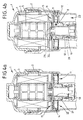
- Fig. 2 shows a second embodiment in which the anti-return valve 11 and the drain valve 22 in contrast to first embodiment have other valve bodies 12, this valve body 12 similar or identical to the Valve body 7 of the filter bypass valve are configured.
- the combination component 15 forms in this embodiment both the base plate 14 and the support dome 6 from so that with the assembly only this one assembly, namely of the combination component 15, all valve functions in the filter 1 can be installed.
- the particularly simple manufacture and assembly of the combination component 15 is also at this embodiment in that the Valve bodies 7 and 12 associated valve seats not on this Combination component 15 are provided, but on the housing side or on the filter insert 4.
- FIG. 3 shows in a similar embodiment like the embodiment of FIG. 2, however Combination component 15, which is similar to the embodiment 1 separately from the dome 6 and only subsequently in the manner known from FIG. 1 the support dome 6 is connected.
- Combination component 15 which is similar to the embodiment 1 separately from the dome 6 and only subsequently in the manner known from FIG. 1 the support dome 6 is connected.
- On particularly inexpensive Way can use in this embodiment different support domes 6 an adaptation to different Filter dimensions are done.
- On particularly simple ones Way by using filter inserts of different heights 4 an adaptation to the filter area required in each case take place, always using the same filter housing 2 is possible and accordingly only of different heights Cover 3 must be used.
- FIGS. 4a and 4b an embodiment is shown at which the pipe socket 18 as a separate component of the combination component 15 is designed so that easy adjustment to the respective outlet of different filter types when in use a standardized base plate 14 is possible.
- This Pipe socket 18 of FIGS. 4a and 4b is not by a retaining ring held in the filter housing 2.
- the pipe socket forms 18 in this embodiment also the movable Valve body of the filter bypass valve, which in this Embodiment provided below the filter insert 4 is.
- the filter 1 is in the operating state of the engine standstill shown. Both the anti-return valve 11 and the drain valve 22 are closed. By the force of a spring 27, the pipe socket 18 against the base plate 14 of the Combination component 15 pressed.
- Fig. 4b shows the operating state in which the Engine runs and a certain oil pressure is built up.
- a cold start can be due to the high oil viscosity here the oil pressure can be reached at which the filter bypass valve opens.
- the oil first arrives through the inlet 23 the valve body 12 of the anti-return valve 11 and opens this valve.
- the oil continues to flow and is distributed throughout the interior of the filter housing 2 around the filter insert 4. Due to the high Oil viscosity does not allow the oil to flow into the interior quickly enough 5, so that outside of the filter insert 4 in the filter 1 builds up an overpressure, which finally on a flange plate 28 presses on the pipe socket 18 so that the pipe socket 18 against the Effect of the spring 27 is pressed down.
- the exemplary embodiments shown relate exclusively Filter types in which the drain, like the drain line 32, is decentralized is arranged, i.e. runs radially outside the outlet, for example, axially parallel.
- filter types which have a so-called central drain.
- the oil initially flows in its own, within the outlet opening provided flow channel, the z. B. coaxial around the actual outlet duct, through a partition separated, runs and then branches off from the outlet.
- filters with a central outlet can also be used advantageously according to the invention be designed.
Abstract
Description
Die Erfindung betrifft einen Filter nach dem Oberbegriff des Anspruchs 1, wie er beispielsweise als Ölfilter für Verbrennungsmotoren in der Automobilindustrie einsetzbar ist. Ein derartiger Filter ist aus der GB-A-227,97,25 oder aus der DE-A-421,45,00 bekannt. Diese bekannten Filter weisen jeweils ein Kombinationsbauteil mit einem Ventilkörper auf sowie mit den zugeordneten Ventilsitz.The invention relates to a filter according to the preamble of the claim 1, for example as an oil filter for internal combustion engines can be used in the automotive industry. Such a filter is from GB-A-227.97.25 or from DE-A-421.45.00 known. These known filters each have a combination component with a valve body on and with the associated Valve seat.
In einem Ölfilter für Verbrennungsmotoren in der Automobilindustrie können eir. oder mehrere Ventile vogeshen sein wie zum Beispiel erstens ein Rücklauf-Sperrventil, welches aufgrund des vom Motor aufgebauten Öldrucks öffnet, wenn das Öl in den Filter einströmt. Bei Motorstillstand und dementsprechend abgefallenem Öldruck schließt das Rücklauf-Sperrventil und stellt so eine Mindestölmenge innerhalb des Filters sicher. Zweitens kann ein Filterumgehungsventil vorgesehen sein, um bei stark verschmutztem Filtermedium oder bei zu großer Viskosität des Öls einen kurzschlußartigen Betrieb des Filters zu ermöglichen. Dabei wird bei einem bestimmten Überdruck, der auf der Rohölseite des Filters herrscht, das Filterumgehungsventil geöffnet und eine Passage zu dem Filter-Auslaß, der an sich für das Reinöl vorgesehen ist, geöffnet. Dritens kann ein Ablassventil vorgesehen sein, das dann, wenn der Filter geöffnet wird, um den Filtereinsatz zu wechseln, in Abhängigkeit von der Bewegung des Deckels und des Filtereinsatzes öffnet, so daß im Innenraum des Filtergehäuses befindliches Öl abfließen kann. Hierdurch wird eine möglichst verschmutzungsarme Entnahme des Filtereinsatzes ermöglicht.In an oil filter for internal combustion engines in the automotive industry can eir. or several valves have been installed First example, a return check valve, which due to the Oil pressure built up by the engine opens when the oil enters the filter flows. When the engine is at a standstill and has fallen off accordingly Oil pressure closes the anti-return valve and sets one Minimum amount of oil inside the filter safe. Second, can a filter bypass valve may be provided to check for heavily soiled Filter medium or if the oil viscosity is too high to enable short-circuit operation of the filter. there is at a certain overpressure on the crude oil side of the filter prevails, the filter bypass valve is opened and a passage to the filter outlet, which in itself is for the pure oil is intended to be opened. Third, a drain valve can be provided be that when the filter is opened to the filter insert to change depending on the movement of the Lid and the filter insert opens, so that in the interior oil from the filter housing can drain off. hereby removal of the filter insert with as little contamination as possible allows.
Bei dem Kombinationsbauteil der gattungsgemäßen Filter muß erstens der Ventilsitz hergestellt werden und zweitens erschwert dieser die Herstellung des Kombinationsbauteils, da entweder der Ventilkörper oder der Ventilsitz schlecht zugänglich ist.In the combination component of the generic filter must firstly the valve seat are made and secondly difficult this the manufacture of the combination component, since either the valve body or valve seat is difficult to access.
Der Erfindung liegt die Aufgabe zugrunde, einen gattungsgemäßen Filter dahingehend zu verbessern, daß dieser möglichst preisgünstig hergestellt und insbesondere schnell montiert werden kann.The invention has for its object a generic To improve the filter so that this is possible manufactured inexpensively and, in particular, assembled quickly can.
Diese der Erfindung zugrundeliegende Aufgabe wird durch einen Filter mit den Merkmalen des Anspruches 1 gelöst.This object on which the invention is based is achieved by solved a filter with the features of claim 1.
Die Erfindung schlägt mit anderen Worten vor, zusätzlich zu dem Ventil weitere Funktionen in einem Kombinationsbauteil zu vereinigen, z. B. mehrere Ventilfunktionen. Da der Ventilsitz von dem Kombinationsbauteil getrennt angeordnet ist, wird die Montage bei der Herstellung des Kombinationsbauteils erleichtert und in kürzerer Zeit möglich. Da erst mit der Endmontage des Filters ein funktionsfähiges Ventil erstellt wird, ist eine besonders einfache Vormontage des Kombinationsbauteiles möglich, weil dieses die Ventilkörper in einer Weise aufnehmen bzw. aufweisen kann, daß sie noch nicht an ihren Ventilsitzen anliegen müssen, daher besonders leicht zugänglich sind und dementsprechend einfach und schnell montiert werden können. Die zugeordneten Ventilsitze können demgegenüber beispielsweise vom Filtergehäuse bzw. Filtersockel ausgebildet werden oder vom Filtereinsatz, so dass sich zusätzlich zu der Herstellungsvereinfachung vorteilhaft ergibt, dass ein Bauteil, nämlich ein als eigenes Bauteil augestalteter Ventilsitz, eingespart werden kann.In other words, the invention proposes in addition to the valve further functions in a combination component unite e.g. B. multiple valve functions. Since the valve seat from the combination component is arranged separately, the assembly facilitated in the manufacture of the combination component and possible in less time. Since only with the final assembly of the Filters a working valve is a special one simple pre-assembly of the combination component possible because this take up or have the valve body in a manner can that they are not yet in contact with their valve seats must therefore be particularly easily accessible and accordingly can be installed easily and quickly. The assigned In contrast, valve seats can, for example are formed by the filter housing or filter base or from the filter insert, so that in addition to the manufacturing simplification advantageously results in a component, namely a as Own component designed valve seat, can be saved.
Eine schnelle Montage des Filters wid durch Verwendung vorgefertigter Baugruppen ermöglicht. Insbesondere wenn Teile des Filters, wie beispielsweise der Filtersockel, am Motorgehäuse einteilig angegossen vorgesehen sind, erfolgt die Montage bzw. Komplettierung zur Fertigstellung des Filters im Automobilwerk. Anstelle einer vollautomatisierten Fertigstellung eines kompletten Filters beim Filterhersteller wird die Herstellung teilweise zum Automobilhersteller verlagert, so daß hier eine erhebliche Vereinfachung der Montage und damit eine kostengünstigere Fertigung dadurch erzielt werden kann, daß die Anzahl der zu montierenden Bauteile verringert werden kann.The filter can be installed quickly by using pre-made filters Assemblies enabled. Especially if parts of the Filters, such as the filter base, on the motor housing are provided in one piece, the assembly or Completion to complete the filter in the automotive plant. Instead of a fully automated completion of a complete Filters at the filter manufacturer are partially used for Automobile manufacturers relocated, so that a considerable simplification assembly and thus more cost-effective production can be achieved in that the number of to be assembled Components can be reduced.
Zusätzlich zu dem an sich vorgesehenen ersten Ventil, beispielsweise dem Rücklauf-Sperrventil, kann daher das Kombinationsbauteil entweder das Umgehungsventil oder das Ablassventil aufweisen oder ggf. beide, wobei außer dem vorerwähnen ersten Ventil komplette Ventile vorgesehen sein können, die jeweils den beweglichen Ventilkörper aufweisen sowie die dem Ventilkörper zugeordnete, als Ventilsitz bezeichnete Dichtungsfläche. Vorteilhaft jedoch kann vorgesehen sein, daß auch bei den zusätzlich vogsehenen Ventilen erst mit der Endmontage des Filters jeweils ein funktionsfähiges Ventil erstellt wird. In diesem Fall ist eine besonders einfache Vormontage des Kombinationsbauteiles möglich, weil dieses die Ventilkörper in einer Weise aufnehmen bzw. aufweisen kann, daß sie noch nicht an ihren Ventilsitzen anliegen müssen, daher besonders leicht zugänglich sind und dementsprechend einfach und schnell montiert werden können. Die zugeordneten Ventilsitze können demgegenüber beispielsweise vom Filtergehäuse bzw. Filtersockel ausgebildet werden oder vom Filtereinsatz.In addition to the first valve provided per se, for example the anti-return valve, the combination component can either the bypass valve or the drain valve have, or possibly both, apart from the aforementioned first valve complete valves can be provided, each have the movable valve body and the Sealing surface assigned to the valve body and referred to as the valve seat. However, it can advantageously be provided that also at the additionally seen valves only with the final assembly a functional valve is created for each filter. In this The case is a particularly simple pre-assembly of the combination component possible because this is the valve body in a way can record or have that they are not yet in their Valve seats must be in contact, so they are particularly easily accessible and are therefore easy and quick to assemble can. The assigned valve seats, on the other hand, can formed for example by the filter housing or filter base or from the filter insert.
Alternativ zur Anordnung eines oder mehrerer weiterer Ventile kann das Kombinationsbauteil mit anderen Bauteilen des Filters verbunden oder verbindbar sein, um eine schnelle Montage durch hochintegrierte Baugruppen zu ermöglichen. So kann vorgesehen sein, das Kombinationsbauteil mit einem Filtereinsatz oder einem an sich bekannten Stützdom für den Filtereinsatz zu verbinden. Im Automobilwerk muß der Filtereinsatz vielfach, je nach Filtertyp, ohnehin montiert werden, so daß hier durch die nun mögliche gleichzeitige Montage eines oder mehrerer Ventile Arbeitsschritte eingespart werden können.As an alternative to arranging one or more other valves can the combination component with other components of the filter be connected or connectable for quick assembly made possible by highly integrated assemblies. So can be provided be the combination component with a filter insert or a well-known support dome for the filter insert connect. In the automobile plant, the filter insert has to be used many times according to filter type, to be installed anyway, so that here by the now possible simultaneous installation of one or more valves Steps can be saved.
Bei Verbindung mit einem Filtereinsatz, dessen regelmäßiger Wechsel vorgesehen ist, kann der Filtereinsatz vorteilhaft lösbar mit dem Kombinationsbauteil verbunden sein, z. B. durch eine schwach haltende Clips- bzw. Schnappverbindung, so daß beide gemeinsam zunächst als eine einheitliche Baugruppe montiert werden können. Das Kombinationsbauteil kann dann jedoch ökologisch und ökonomisch vorteilhaft als filterfestes Lebensdauerteil im Filter verbleiben und bei einem Wechsel des Filtereinsatz problemlos vom Filtereinsatz gelöst werden.When connected to a filter insert, its regular If the change is provided, the filter insert can advantageously be released be connected to the combination component, e.g. B. by a weak clip or snap connection, so that both first assembled together as a single assembly can be. The combination component can then be ecological and economically advantageous as a filter-proof life part remain in the filter and when changing the filter insert can be easily removed from the filter insert.
Ausführungsbeispiele der Erfindung, die jeweils Filtertypen mit einem dezentralen Ölablass betreffen, werden anhand der Zeichnungen im folgenden näher erläutert. Dabei zeigt
- Fig. 1a - 1d
- ein erstes Ausführungsbeispiel, wobei in den Fig. 1a - 1 c der gesamte Filter in verschiedenen Betriebszuständen dargestellt ist und in Fig. 1d das Kombinationsbauteil in Alleinstellung,
- Fig. 2 und 3
- jeweils ein weiteres Ausführungsbeispiel, und
- Fig. 4a - 4b
- ein weiteres Ausführungsbeispiel, ebenfalls in verschiedenen Betriebszuständen.
- 1a-1d
- a first embodiment, wherein the entire filter is shown in different operating states in FIGS. 1a-1c and in FIG. 1d the combination component in isolation,
- 2 and 3
- each another embodiment, and
- Figures 4a - 4b
- a further embodiment, also in different operating states.
In Fig. 1a ist ein Filter 1, der als Ölfilter für einen Verbrennungsmotor
vorgesehen ist, im Zustand des Motorstillstandes dargestellt.
Der Filter 1 weist ein Filtergehäuse 2 und einen Deckel 3
auf sowie einen auswechselbaren Filtereinsatz 4. Der Filtereinsatz
4 umschließt einen Innenraum 5, in dem ein Stützdom 6
angeordnet ist, der ein Kollabieren des Filtermaterials des Filtereinsatzes
4 bei den im Ölfilter herrschenden Druck- und Temperaturbedingungen
verhindert.In Fig. 1a is a filter 1, which acts as an oil filter for an internal combustion engine
is provided, shown in the state of engine standstill.
The filter 1 has a
Der Stützdom 6 hält einen Ventilkörper 7 eines Filterumgehungsventils
8: Bei außerhalb des Filtereinsatzes 4 herrschendem
großen Druck wird der Ventilkörper 7 nach unten gedrückt
und öffnet dabei einen Strömungsweg zwischen dem Ventilkörper
7 und seinem zugeordneten Ventilsitz, der durch einen Kragen
9 gebildet wird, welcher von einer oberen Endscheibe 10
des Filtereinsatzes 4 gebildet ist.The
Weitere Ventile des Filters 1 sind in Form von zwei grundsätzliche
gleich ausgestalteten Ventilen vorgesehen, die jeweils einen
Ventilkörper 12 in Form eines Plättchens aufweisen und die als
Rücklauf-Sperrventil 11 und als Ablassventil 22 dienen Die Ventilkörper
12 stützen sich jeweils mittels einer Druckfeder gegen
eine Grundplatte 14 eines Kombinationsbauteiles 15 ab, welches
im einzelnen aus Fig. 1d ersichtlich ist:Other valves of filter 1 are in the form of two basic ones
Identically designed valves are provided, each one
Have
An der Grundplatte 14 sind für das Rücklauf-Sperrventil 11 und
das Ablassventil 22 Halterungen 16 vorgesehen, gegen welche
die Ventilkörper 12 durch Federn 17 gedrückt werden. Auf diese
Weise sind die Ventilkörper 12 unverlierbar am Kombinationsbauteil
15 gehalten, so daß das Kombinationsbauteil 15 vormontiert
versandfertig ist und die Montage des Kombinationsbauteiles
15 beim Einsatz in ein Filtergehäuse 2 erleichtert wird.On the
Weiterhin weist das Kombinationsbauteil 15 einen Rohrstutzen
18 auf. Der Rohrstutzen 18 trägt eine Dichtung 19, beispielsweise
aus einem Elastomer, und einen Haltering 20, beispielsweise
aus Metall, der in der Hinterschneidung von federelastischen
Haltekrallen 21 angeordnet ist. Der Haltering 20
kann durch seine Spreizkraft den Rohrstutzen 18 innerhalb des
Filtersockels halten, ohne daß Hinterschneidungen erforderlich
sind, so daß eine aufwendige Bearbeitung des Filtersockels zur
Aufnahme der Haltekrallen 21 nicht erforderlich ist.Furthermore, the
In Fig. 1 b ist die übliche Betriebsstellung des Filters 1 dargestellt.
Dabei ist der Ventilkörper 12 des Rücklauf-Sperrventiles
11 durch Öl angehoben, welches durch einen Zulauf 23 in den
Filter 1 einströmt. Gefiltertes Öl gelangt durch einen Auslaß 31
zu den Schmierstellen. Das Ablassventil 22 hingegen ist geschlossen,
da sein Ventilkörper 12 auf dem zugehörigen Ventilsitz
aufliegt, der von dem Filtergehäuse 2 gebildet ist, so daß
kein Öl aus dem oberhalb des Kombinationsbauteils 15 befindlichen
Filterinneren in eine Ablaßleitung 32 gelangen kann.In Fig. 1 b, the usual operating position of the filter 1 is shown.
The
In Fig. 1 c ist der Betriebszustand des "Filterwechsels" dargestellt,
bei dem nicht der komplette Filter 1, sondern lediglich der
Filtereinsatz 4 gewechselt wird. Dabei ist ersichtlich,daß der Deckel
3 bereits gegenüber dem Filtergehäuse 2 angehoben ist. 1 c shows the operating state of the "filter change",
where not the complete filter 1, but only the
Der Rohrstutzen 18 des Kombinationsbauteiles 15 ist mit dem
Stützdom 6 verclipst, wobei sich der Stützdom 6 mittels einiger
Haltekrallen 24 hinter einen Kragen 25 erstreckt, der am Rohrstutzen
18 vorgesehen ist. Der Rohrstutzen 18 und damit das
gesamte Kombinationsbauteil 15 wird also gemeinsam mit dem
Deckel 3 gegenüber dem Filtergehäuse 2 angehoben, beispielsweise
durch einen Klemmsitz des Filtereinsatzes 4 am
Stützdom 6 aufgrund deren abdichtender Verbindung miteinander,
oder mit Hilfe einer Feder 27.The
Der Haltering 20 begrenzt den nach oben möglichen Weg des
Kombinationsbauteiles 15, entweder allein aufgrund seiner
Klemmkraft, oder mit Hilfe einer umlaufenden Nut, die im Filtergehäuse
2 vorgesehen ist und die eine höhenfixierte Stellung
des Halteringes 20 im Filtergehäuse 2 sicherstellt.
In dieser angehobenen Stellung des Kombinationsbauteiles 15
ist - wie aus Fig. 1c ersichtlich - der Ventilkörper 12 des
Ablassventiles 22 von seinem zugeordneten Ventilsitz abgehoben,
so daß Restöl aus dem Innenraum 5 und insgesamt aus
dem Filtergehäuse 2 in eine Ablassleitung 26 einströmen kann.
Die Gewindelänge zwischen Deckel 3 und Filtergehäuse 2 ermöglicht
dabei einen vollständigen Ablass dieses Restöles, so
daß bei Entnahme des Filtereinsatzes 4 aus dem Filtergehäuse
2 das Restöl möglichst rückstandsfrei vom Filtereinsatz 4 abgetropft
ist.The retaining
In this raised position of the
Fig. 2 zeigt ein zweites Ausführungsbeispiel, bei dem das Rücklauf-Sperrventil
11 und das Ablassventil 22 im Gegensatz zum
ersten Ausführungsbeispiel andere Ventilkörper 12 aufweisen,
wobei diese Ventilkörper 12 ähnlich oder baugleich mit dem
Ventilkörper 7 des Filterumgehungsventiles ausgestaltet sind.
Das Kombinationsbauteil 15 bildet bei diesem Ausführungsbeispiel
sowohl die Grundplatte 14 als auch den Stützdom 6 aus,
so daß mit der Montage lediglich dieser einen Baugruppe, nämlich
des Kombinationsbauteiles 15, sämtliche Ventilfunktionen in
den Filter 1 eingebaut werden. Die besonders einfache Herstellung
und Montage des Kombinationsbauteiles 15 wird auch bei
diesem Ausführungsbeispiel dadurch ermöglicht, daß die den
Ventilkörpern 7 bzw. 12 zugeordneten Ventilsitze nicht an diesem
Kombinationsbauteil 15 vorgesehen sind, sondern gehäuseseitig
bzw. am Filtereinsatz 4.Fig. 2 shows a second embodiment in which the
Das Ausführungsbeispiel gemäß Fig. 3 zeigt in ähnlicher Ausgestaltung
wie das Ausführungsbeispiel der Fig. 2 allerdings ein
Kombinationsbauteil 15, welches ähnlich wie bei dem Ausführungsbeispiel
der Fig. 1 separat vom Stützdom 6 hergestellt und
lediglich anschließend auf die aus Fig. 1 bekannte Weise mit
dem Stützdom 6 verbunden ist. Auf besonders preisgünstige
Weise kann bei diesem Ausführungsbeispiel durch Verwendung
unterschiedlicher Stützdome 6 eine Anpassung an unterschiedliche
Filterabmessungen erfolgen. Auf besonders einfache
Weise kann durch die Verwendung unterschiedlich hoher Filtereinsätze
4 eine Anpassung an die jeweils erforderliche Filterfläche
erfolgen, wobei die Verwendung stets gleicher Filtergehäuse
2 möglich ist und dementsprechend lediglich unterschiedlich hohe
Deckel 3 Verwendung finden müssen.3 shows in a similar embodiment
like the embodiment of FIG. 2, however
In den Fig. 4a und 4b ist ein Ausführungsbeispiel dargestellt, bei
dem der Rohrstutzen 18 als eigenes Bauteil des Kombinationsbauteiles
15 ausgestaltet ist, so daß eine einfache Anpassung
an den jeweiligen Auslaß unterschiedlicher Filtertypen bei Verwendung
einer standardisierten Grundplatte 14 möglich ist. Dieser
Rohrstutzen 18 der Fig. 4a und 4b ist nicht durch einen Haltering
im Filtergehäuse 2 gehalten. Zudem bildet der Rohrstutzen
18 bei diesem Ausführungsbeispiel auch den beweglichen
Ventilkörper des Filterumgehungsventils, welches bei diesem
Ausführungsbeispiel unterhalb des Filtereinsatzes 4 vorgesehen
ist.4a and 4b, an embodiment is shown at
which the
In Fig. 4a ist der Filter 1 im Betriebszustand des Motorstillstandes
dargestellt. Sowohl das Rücklauf-Sperrventil 11 als auch
das Ablassventil 22 sind geschlossen. Durch die Kraft einer Feder
27 wird der Rohrstutzen 18 gegen die Grundplatte 14 des
Kombinationsbauteiles 15 gedrückt.4a, the filter 1 is in the operating state of the engine standstill
shown. Both the
Demgegenüber zeigt Fig. 4b den Betriebszustand, bei dem der
Motor läuft und ein bestimmter Öldruck aufgebaut ist. Beispielsweise
bei einem Kaltstart kann aufgrund der hohen Ölviskosität
hier der Öldruck erreicht werden, bei dem das Filterumgehungsventil
öffnet. Zunächst gelangt das Öl durch den Zulauf 23 an
den Ventilkörper 12 des Rücklauf-Sperrventiles 11 und öffnet
dieses Ventil. Das Öl fließt weiter und verteilt sich im Innenraum
des Filtergehäuses 2 um den Filtereinsatz 4. Aufgrund der hohen
Ölviskosität strömt das Öl nicht schnell genug in den Innenraum
5, so daß sich außerhalb des Filtereinsatzes 4 im Filter 1
ein Überdruck aufbaut, der schließlich auf eine Flanschplatte 28
am Rohrstutzen 18 drückt, so daß der Rohrstutzen 18 gegen die
Wirkung der Feder 27 herabgedrückt wird. Mehrere Fenster 29
sind zwischen Haltekrallen 30 vorgesehen, durch die der Rohrstutzen
18 mit der Grundplatte 14 verbunden ist. Durch diese
Fenster gelangt nun das Öl unmittelbar in einen Auslaß 31, der
an sich für das Reinöl vorgesehen ist. Das Filterumgehungsventil
8 wird bei diesem Ausführungsbeispiel also durch den Rohrstutzen
18 und die Grundplatte 14 gebildet, so daß auch bei diesem
Ausführungsbeispiel sämtliche Ventilfunktionen in dem
Kombinationsbauteil 15 verwirklicht sind.In contrast, Fig. 4b shows the operating state in which the
Engine runs and a certain oil pressure is built up. For example
a cold start can be due to the high oil viscosity
here the oil pressure can be reached at which the filter bypass valve
opens. The oil first arrives through the
Die dargestellten Ausführungsbeispiele betreffen ausschließlich
Filtertypen, bei denen der Ablaß wie die Ablaßleitung 32 dezentral
angeordnet ist, also radial außerhalb des Auslasses verläuft,
beispielsweise achsparallel. Demgegenüber sind auch Filtertypen
bekannt, die einen sogenannten zentralen Ablaß aufweisen.
Dabei strömt das Öl zunächst in einem eigenen, innerhalb
der Auslaßöffnung vorgesehenen Strömungskanal, der z. B. koaxial
um den eigentlichen Auslaßkanal, durch eine Trennwand
abgetrennt, verläuft und der anschließend vom Auslaß abzweigt.
Auch derartige Filter mit zentralem Auslaß können vorteilhaft erfindungsgemäß
ausgestaltet sein.The exemplary embodiments shown relate exclusively
Filter types in which the drain, like the
Claims (4)
- Filter, like an oil filter for an internal combustion engine, incorporating a filter housing,
and with a valve arranged in the filter housing, a non-return valve, a filter bypass valve or a drain valve,
where the body of this valve is arranged on a combination component (15),
and the combination component (15) incorporates connecting means for the connection of at least one other filter component such as another valve or a filter insert (4), to the combination component (15),
characterised in that the combination component (15) incorporates a base plate (14), on which the valve body is spring-mounted, where the valve seat assigned to the valve body is arranged so as to be separate from the combination component (15). - Filter in accordance with claim 1, characterised in that the base plate (14) incorporates a hole, to which a pipe socket (18) forming the valve body for the drain valve and/or the filter bypass valve (8) is connected.
- Filter in accordance with claim 2, characterised in that the pipe socket (18) is constructed as a separate component from the base plate (14)
- Filter in accordance with one of the foregoing claims,
characterised in that the combination component (15) incorporates connecting means to which a filter insert (4) is detachably attached or can be attached.
Applications Claiming Priority (3)
| Application Number | Priority Date | Filing Date | Title |
|---|---|---|---|
| DE29915844U DE29915844U1 (en) | 1999-09-09 | 1999-09-09 | Filters with valve combination component |
| DE29915844U | 1999-09-09 | ||
| PCT/DE2000/003125 WO2001017658A2 (en) | 1999-09-09 | 2000-09-08 | Filter with a valve combination component |
Publications (2)
| Publication Number | Publication Date |
|---|---|
| EP1210165A2 EP1210165A2 (en) | 2002-06-05 |
| EP1210165B1 true EP1210165B1 (en) | 2003-12-17 |
Family
ID=8078664
Family Applications (1)
| Application Number | Title | Priority Date | Filing Date |
|---|---|---|---|
| EP00972584A Expired - Lifetime EP1210165B1 (en) | 1999-09-09 | 2000-09-08 | Filter with a valve combination component |
Country Status (5)
| Country | Link |
|---|---|
| US (1) | US7029575B1 (en) |
| EP (1) | EP1210165B1 (en) |
| KR (1) | KR100679771B1 (en) |
| DE (2) | DE29915844U1 (en) |
| WO (1) | WO2001017658A2 (en) |
Families Citing this family (13)
| Publication number | Priority date | Publication date | Assignee | Title |
|---|---|---|---|---|
| DE29915844U1 (en) | 1999-09-09 | 2001-01-25 | Hengst Walter Gmbh & Co Kg | Filters with valve combination component |
| JP3804949B2 (en) * | 2002-11-12 | 2006-08-02 | トヨタ紡織株式会社 | Fluid filter and drain mechanism thereof, drain jig used in fluid filter, and fluid filter drain method |
| US20060006124A1 (en) * | 2004-07-12 | 2006-01-12 | Yates Brian G | Filter cartridge and method and apparatus for replacing same |
| DE102005045012A1 (en) * | 2005-09-21 | 2007-04-05 | Hydac Filtertechnik Gmbh | filter means |
| US7897046B2 (en) * | 2006-01-25 | 2011-03-01 | Baldwin Filters, Inc. | Fluid filter |
| DE202007006385U1 (en) * | 2006-05-10 | 2007-09-20 | Hengst Gmbh & Co.Kg | Liquid filter with return valve in the clean-side flow channel |
| US7771596B2 (en) * | 2007-01-24 | 2010-08-10 | Wix Filtration Corp Llc | Filter Container, assembly and method for manufacturing the same |
| US8747665B2 (en) * | 2007-01-24 | 2014-06-10 | Wix Filtration Corp Llc | Filter container, assembly, and method for manufacturing the same |
| DE102009014934A1 (en) * | 2009-03-25 | 2010-10-14 | Mahle International Gmbh | liquid filters |
| US20140027361A1 (en) * | 2012-07-24 | 2014-01-30 | Lancer Corporation | Filtration system |
| US10406463B2 (en) * | 2015-09-11 | 2019-09-10 | Hydac Technology Corporation | Filter device and filter element for such a device |
| EP3907397B1 (en) | 2020-03-30 | 2023-06-07 | Hamilton Sundstrand Corporation | Fuel filter assembly |
| EP3904667A1 (en) | 2020-04-28 | 2021-11-03 | Hamilton Sundstrand Corporation | Fuel filter assembly |
Family Cites Families (17)
| Publication number | Priority date | Publication date | Assignee | Title |
|---|---|---|---|---|
| US3268077A (en) * | 1963-04-10 | 1966-08-23 | Chrysler Corp | Dual element, dual valve filter |
| JPH04225806A (en) * | 1990-12-27 | 1992-08-14 | Kanebo Ltd | Dual construction filter container |
| DE4131353A1 (en) * | 1991-03-28 | 1992-10-01 | Knecht Filterwerke Gmbh | Fluid filter with annular element - has only element interchangeable |
| DE4201041A1 (en) * | 1991-09-20 | 1993-07-22 | Knecht Filterwerke Gmbh | Filter for liquids, esp. internal combustion engine lubricants |
| EP0653234B1 (en) * | 1991-03-28 | 1997-06-04 | Knecht Filterwerke Gmbh | Liquid filter |
| DE4140140C2 (en) * | 1991-07-23 | 2002-11-28 | Mahle Filtersysteme Gmbh | Screw-on filter for liquids |
| ATE184502T1 (en) * | 1991-12-17 | 1999-10-15 | Mann & Hummel Filter | FILTER FOR FUEL AND/OR LUBRICANTS OF AN INTERNAL COMBUSTION ENGINE |
| DE4214500C2 (en) | 1992-05-07 | 1996-05-09 | Hengst Walter Gmbh & Co Kg | Bypass or pressure relief valve for installation in liquid-carrying devices, in particular liquid filters |
| DE4243217C2 (en) * | 1992-12-19 | 2003-04-30 | Mahle Filtersysteme Gmbh | liquid filters |
| DE4303694B4 (en) * | 1993-02-09 | 2004-01-29 | Mahle Filtersysteme Gmbh | Liquid filter with overflow valve |
| GB2279725A (en) | 1993-07-09 | 1995-01-11 | Pall Corp | Combined check and pressure-relief valve |
| DE9411212U1 (en) * | 1994-07-13 | 1994-09-01 | Hengst Walter Gmbh & Co Kg | Liquid filter |
| DE4446263C2 (en) | 1994-12-23 | 1996-11-14 | Knecht Filterwerke Gmbh | Valve rod for a filter housing with a sealing cover and a pot-shaped lower part |
| DE19539918C1 (en) * | 1995-10-27 | 1997-02-06 | Hengst Walter Gmbh & Co Kg | Liquid filter, in particular for oil or fuel of an internal combustion engine, and matching filter connection flange on the machine side |
| DE29610290U1 (en) * | 1996-06-12 | 1996-08-22 | Hengst Walter Gmbh & Co Kg | Liquid filter |
| US6068763A (en) * | 1997-09-12 | 2000-05-30 | Purolator Products Company | Spin-on oil filter with replaceable element |
| DE29915844U1 (en) | 1999-09-09 | 2001-01-25 | Hengst Walter Gmbh & Co Kg | Filters with valve combination component |
-
1999
- 1999-09-09 DE DE29915844U patent/DE29915844U1/en not_active Expired - Lifetime
-
2000
- 2000-09-08 DE DE50004812T patent/DE50004812D1/en not_active Expired - Lifetime
- 2000-09-08 US US10/070,781 patent/US7029575B1/en not_active Expired - Fee Related
- 2000-09-08 WO PCT/DE2000/003125 patent/WO2001017658A2/en active IP Right Grant
- 2000-09-08 EP EP00972584A patent/EP1210165B1/en not_active Expired - Lifetime
- 2000-09-08 KR KR1020027003181A patent/KR100679771B1/en not_active IP Right Cessation
Also Published As
| Publication number | Publication date |
|---|---|
| EP1210165A2 (en) | 2002-06-05 |
| DE50004812D1 (en) | 2004-01-29 |
| WO2001017658A3 (en) | 2001-09-13 |
| DE29915844U1 (en) | 2001-01-25 |
| KR100679771B1 (en) | 2007-02-07 |
| WO2001017658A2 (en) | 2001-03-15 |
| KR20020048403A (en) | 2002-06-22 |
| US7029575B1 (en) | 2006-04-18 |
Similar Documents
| Publication | Publication Date | Title |
|---|---|---|
| EP1137470B1 (en) | Fluid filter with a discharge dome that is fixed to the housing | |
| EP0699826B1 (en) | Fluid circuit with a filter in the main flow | |
| EP1154831B1 (en) | Fluid filter with removable central component with additional retainer | |
| DE19605425C2 (en) | Liquid filter with filter bypass valve and sealing surface on the filter element side | |
| DE102014006852B4 (en) | Hollow filter element, filter housing and filter | |
| DE102004002995B4 (en) | Thermostatic valve assembly | |
| EP1210165B1 (en) | Filter with a valve combination component | |
| EP2654918A1 (en) | Liquid filter having a filter bypass valve and filter insert therefor | |
| DE102010062813A1 (en) | Fuel filter | |
| DE102016124587A1 (en) | Positioning device with a positioning guide for positioning a first component relative to a second component to be connected in the circumferential direction thereof | |
| DE202005007870U1 (en) | Filter device, in particular for liquid filtration in internal combustion engines | |
| EP2864016B1 (en) | Liquid filter with a filter bypass valve and with a central discharge duct, and filter insert for a liquid filter | |
| EP1648583A1 (en) | Oil filter arrangement and filter element | |
| EP2353692A2 (en) | Filter device | |
| DE102015015370A1 (en) | Filter device for an oil filter of a motor vehicle and oil filter | |
| DE202007017980U1 (en) | Filter cartridge and oil filter of an internal combustion engine | |
| EP1194206B1 (en) | Filter and corresponding filter insert with direct sealing | |
| DE10036939B4 (en) | check valve | |
| DE102017109924A1 (en) | End plate, filter element, filter system and method for filtering liquid | |
| DE102010004778B4 (en) | Valve for controlling a fluid flow | |
| EP2129902B1 (en) | Liquid filter | |
| DE10235902A1 (en) | Oil filter for motor vehicle has filter element pressing on closing part, movement between positions of which is controllable by fitting and removing filter element | |
| EP3727641B1 (en) | Filter system with non-return valve and filter element | |
| DE102020124605A1 (en) | Oil filter with filter bypass valve and filter bypass valve | |
| DE102015002173B4 (en) | flow valve |
Legal Events
| Date | Code | Title | Description |
|---|---|---|---|
| PUAI | Public reference made under article 153(3) epc to a published international application that has entered the european phase |
Free format text: ORIGINAL CODE: 0009012 |
|
| 17P | Request for examination filed |
Effective date: 20020307 |
|
| AK | Designated contracting states |
Kind code of ref document: A2 Designated state(s): AT BE CH CY DE DK ES FI FR GB GR IE IT LI LU MC NL PT SE |
|
| RAP1 | Party data changed (applicant data changed or rights of an application transferred) |
Owner name: HENGST GMBH & CO. KG |
|
| GRAP | Despatch of communication of intention to grant a patent |
Free format text: ORIGINAL CODE: EPIDOSNIGR1 |
|
| GRAS | Grant fee paid |
Free format text: ORIGINAL CODE: EPIDOSNIGR3 |
|
| GRAA | (expected) grant |
Free format text: ORIGINAL CODE: 0009210 |
|
| AK | Designated contracting states |
Kind code of ref document: B1 Designated state(s): DE |
|
| REG | Reference to a national code |
Ref country code: IE Ref legal event code: FG4D Free format text: GERMAN |
|
| REF | Corresponds to: |
Ref document number: 50004812 Country of ref document: DE Date of ref document: 20040129 Kind code of ref document: P |
|
| REG | Reference to a national code |
Ref country code: IE Ref legal event code: FD4D |
|
| PLBE | No opposition filed within time limit |
Free format text: ORIGINAL CODE: 0009261 |
|
| STAA | Information on the status of an ep patent application or granted ep patent |
Free format text: STATUS: NO OPPOSITION FILED WITHIN TIME LIMIT |
|
| 26N | No opposition filed |
Effective date: 20040920 |
|
| REG | Reference to a national code |
Ref country code: DE Ref legal event code: R082 Ref document number: 50004812 Country of ref document: DE Representative=s name: HABBEL & HABBEL, DE |
|
| REG | Reference to a national code |
Ref country code: DE Ref legal event code: R082 Ref document number: 50004812 Country of ref document: DE Representative=s name: HABBEL UND HABBEL PATENTANWAELTE PARTG MBB, DE Effective date: 20141118 Ref country code: DE Ref legal event code: R081 Ref document number: 50004812 Country of ref document: DE Owner name: HENGST SE, DE Free format text: FORMER OWNER: HENGST GMBH & CO. KG, 48147 MUENSTER, DE Effective date: 20141118 Ref country code: DE Ref legal event code: R081 Ref document number: 50004812 Country of ref document: DE Owner name: HENGST SE & CO. KG, DE Free format text: FORMER OWNER: HENGST GMBH & CO. KG, 48147 MUENSTER, DE Effective date: 20141118 Ref country code: DE Ref legal event code: R082 Ref document number: 50004812 Country of ref document: DE Representative=s name: HABBEL & HABBEL, DE Effective date: 20141118 |
|
| REG | Reference to a national code |
Ref country code: DE Ref legal event code: R082 Ref document number: 50004812 Country of ref document: DE Representative=s name: HABBEL UND HABBEL PATENTANWAELTE PARTG MBB, DE Ref country code: DE Ref legal event code: R081 Ref document number: 50004812 Country of ref document: DE Owner name: HENGST SE, DE Free format text: FORMER OWNER: HENGST SE & CO. KG, 48147 MUENSTER, DE |
|
| PGFP | Annual fee paid to national office [announced via postgrant information from national office to epo] |
Ref country code: DE Payment date: 20180906 Year of fee payment: 19 |
|
| REG | Reference to a national code |
Ref country code: DE Ref legal event code: R119 Ref document number: 50004812 Country of ref document: DE |
|
| PG25 | Lapsed in a contracting state [announced via postgrant information from national office to epo] |
Ref country code: DE Free format text: LAPSE BECAUSE OF NON-PAYMENT OF DUE FEES Effective date: 20200401 |