EP3989705B1 - Schneidwerk für einen mähdrescher - Google Patents
Schneidwerk für einen mähdrescher Download PDFInfo
- Publication number
- EP3989705B1 EP3989705B1 EP20737333.3A EP20737333A EP3989705B1 EP 3989705 B1 EP3989705 B1 EP 3989705B1 EP 20737333 A EP20737333 A EP 20737333A EP 3989705 B1 EP3989705 B1 EP 3989705B1
- Authority
- EP
- European Patent Office
- Prior art keywords
- cutting
- bar
- cutting bar
- axle
- support frame
- Prior art date
- Legal status (The legal status is an assumption and is not a legal conclusion. Google has not performed a legal analysis and makes no representation as to the accuracy of the status listed.)
- Active
Links
Images
Classifications
-
- A—HUMAN NECESSITIES
- A01—AGRICULTURE; FORESTRY; ANIMAL HUSBANDRY; HUNTING; TRAPPING; FISHING
- A01D—HARVESTING; MOWING
- A01D41/00—Combines, i.e. harvesters or mowers combined with threshing devices
- A01D41/02—Self-propelled combines
-
- A—HUMAN NECESSITIES
- A01—AGRICULTURE; FORESTRY; ANIMAL HUSBANDRY; HUNTING; TRAPPING; FISHING
- A01D—HARVESTING; MOWING
- A01D41/00—Combines, i.e. harvesters or mowers combined with threshing devices
- A01D41/12—Details of combines
- A01D41/14—Mowing tables
- A01D41/141—Automatic header control
-
- A—HUMAN NECESSITIES
- A01—AGRICULTURE; FORESTRY; ANIMAL HUSBANDRY; HUNTING; TRAPPING; FISHING
- A01D—HARVESTING; MOWING
- A01D34/00—Mowers; Mowing apparatus of harvesters
- A01D34/01—Mowers; Mowing apparatus of harvesters characterised by features relating to the type of cutting apparatus
- A01D34/02—Mowers; Mowing apparatus of harvesters characterised by features relating to the type of cutting apparatus having reciprocating cutters
- A01D34/28—Adjusting devices for the cutter-bar
- A01D34/283—Adjustment of the cutter bar in a vertical plane, i.e. to adjust the angle between the cutter bar and the soil
-
- A—HUMAN NECESSITIES
- A01—AGRICULTURE; FORESTRY; ANIMAL HUSBANDRY; HUNTING; TRAPPING; FISHING
- A01D—HARVESTING; MOWING
- A01D41/00—Combines, i.e. harvesters or mowers combined with threshing devices
- A01D41/12—Details of combines
- A01D41/127—Control or measuring arrangements specially adapted for combines
-
- A—HUMAN NECESSITIES
- A01—AGRICULTURE; FORESTRY; ANIMAL HUSBANDRY; HUNTING; TRAPPING; FISHING
- A01D—HARVESTING; MOWING
- A01D41/00—Combines, i.e. harvesters or mowers combined with threshing devices
- A01D41/12—Details of combines
- A01D41/14—Mowing tables
- A01D41/145—Header lifting devices
-
- A—HUMAN NECESSITIES
- A01—AGRICULTURE; FORESTRY; ANIMAL HUSBANDRY; HUNTING; TRAPPING; FISHING
- A01D—HARVESTING; MOWING
- A01D57/00—Delivering mechanisms for harvesters or mowers
- A01D57/01—Devices for leading crops to the mowing apparatus
- A01D57/02—Devices for leading crops to the mowing apparatus using reels
- A01D57/04—Arrangements for changing the position of the reels
Definitions
- the invention relates to a cutting unit for a combine harvester with a support frame for a cutting table, which has a cutting bar on the cutting side which is articulated to the frame and flexible transversely to the cutting direction and which can be adjusted in height relative to the frame by means of several axle levers which are distributed over the width of the cutting unit and which act on the cutting bar at one end and the frame at the other, for which purpose adjusting drives are assigned to the axle levers for the purpose of setting a ground clearance, wherein the adjusting drives and thus the axle levers with the cutting bar can be controlled by a control system to maintain a predetermined ground clearance of the cutting bar across the width of the cutting unit.
- Such a cutting unit is, for example, from the AT 520 625 A2 known.
- a flexible cutting bar is a cutting bar that at least essentially adapts to the contour of the surface to be mown across the direction of travel of the combine harvester, which is usually held to the frame of the cutting unit by means of spring plates or longitudinal control arms. The mown crop is fed via the spring plates for further processing by means of a reel and auger.
- a rigid cutting bar in contrast, is essentially fixed, i.e. immovable, to the frame. Flexible cutting bars are particularly necessary for fruits such as soya, peas, etc.
- At 501 588 A at least one traction means must be provided between the frame and the cutting bar, with which the cutting bar can be displaced relative to the frame by overcoming the spring force from its flexible working position with respect to the frame into a rigid working position with respect to the frame, in which rigid working position the cutting bar is fixed to the frame.
- the WO 2019111069 A1 discloses a cutting unit with belt conveyors that transport cuttings from the edge of the cutting unit to the middle of the cutting unit. To maintain a clearance from the ground, several weighing cells are provided, which measure the weight of the cuttings resting on the cutting unit. Sagging of the cutting unit as a result of the load can be compensated with the adjusting drives. Active adjustment of a clearance from the ground is not provided. The cutting unit can slide over the ground and compensates for the resting weight.
- EP 0160823 A2 known.
- the object of the invention is therefore to create a cutting unit for a combine harvester of the type described above, which enables a quick and easy adjustment of the cutting bar to the respective given harvesting conditions and at the same time ensures an approximately constant cutting height above the ground.
- the invention solves the problem by assigning to the cutting bar several sensors which are distributed over the width of the cutting unit and record the ground clearance of the cutting bar, which are provided in front of each axle lever on the cutting bar in the cutting direction, whereby the sensors Skids arranged on the ground side of the cutting bar for measuring the ground contact pressure of the respective skid or for measuring the distance between the skid and the cutting bar.
- the cutting bar to be quickly and easily adapted to the respective harvesting conditions, whereby an almost constant cutting height above the ground can be maintained across the entire width of the cutting unit. This reliably prevents soil from being pushed up as a result of insufficient clearance from the ground during the harvesting process on uneven ground.
- the sensors should naturally be positioned as far forward as possible on the cutting unit. It is also conceivable to have skids projecting forwards over the cutting unit, to which the sensors are assigned.
- the cutting bar which is flexible across the direction of travel of the combine harvester, is thus actively guided to the contour of the surface to be mown in permitted ranges, for example ⁇ 10-20 cm from a neutral position.
- the control system in particular a vehicle controller, controls the actuators and thus the axle levers with the cutting bar in such a way that a ground clearance of the cutting bar specified by an operator is maintained across the cutting unit width and in particular avoids the cutting bar cutting into the ground.
- Particularly robust sensors suitable for use on a harvesting machine are skids arranged on the ground side of the cutting bar and measure the ground contact pressure of the respective skid with load cells or the distance between the skid and the cutting bar.
- the contact pressure of a skid arranged spring-loaded on the cutting bar corresponds to the distance or can be converted into the distance value.
- At least one sensor is provided on the cutting bar in front of each axle lever in the cutting direction.
- axle levers are designed as articulated parallelograms, which engage one end of the cutting bar and the other end of the frame. This means that the cutting bar is always aligned parallel to the ground during ground tracking and a constant cutting angle is achieved regardless of the ground clearance. This also prevents the cutting bar from twisting transversely to the cutting direction, around a cutting unit transverse axis, which reduces cutting unit wear and the required drive power.
- the axle levers can be attached to the cutting bar via compensating bearings with a swivel axis parallel to the cutting direction.
- a position sensor is assigned to the cutting material feed reel and that the height adjustment and thus the cutting material feed reel can be controlled using the control in such a way that a specified minimum distance between the cutting bar and the cutting material feed reel is maintained. If contact that could damage the reel or blade is to be avoided, a sensor determines the respective position of the reel and raises it accordingly when a collision is imminent and thus out of the danger area.
- the height adjustment can consist of one or two hydraulic cylinders connected in series. If two hydraulic cylinders are provided, one takes over the rough adjustment specified by an operator and the other ensures automatic position correction using the control.
- the described control of the height adjustment for the cutting material feed reel can be used with any known cutting unit with a flexible cutting bar that runs across the cutting direction.
- the support frame with cutting bar and adjusting drives can preferably be guided longitudinally displaceably on a base frame supporting the cutting material feed device for the purpose of adjusting a cutting table length in the cutting direction.
- the actuators are preferably formed in particular by pneumatic cylinders or pneumatic bellows, which are supported on the one hand on the support frame and which, on the other hand, act on an axle lever between a support frame bearing of the axle lever and the cutting bar.
- Actuators can be provided on both sides of the axle lever, which are coupled via a bridge spanning the axle levers, with the bridge acting on the associated axle lever by means of appropriate means.
- the actuator can be integrated into a support frame that is longitudinally displaceable on the base frame, while requiring little space, and the cutting table length can also be adjusted as required within specified limits.
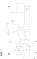
- a cutting unit 1 for a combine harvester 2 comprises a support frame 3 for a cutting table 4, which has a cutting bar 6 on the cutting side, which is attached to the support frame 3 in an articulated manner and is flexible transversely to the cutting direction 5.
- the cutting bar 6 is height-adjustable relative to the support frame 3 by means of several axle levers 7, which are distributed over the width of the cutting unit and engage at one end on the cutting bar 6 and at the other end on the support frame 3.
- adjusting drives 8 are assigned to the axle levers 7, with which the height of the cutting bar 6 can be variably adjusted relative to the support frame 3 across the width of the cutting bar.
- Suitable flexible transition plates 10 are provided for transferring the cutting material away from the cutting bar 6 to a cutting material intake device 9.
- the actuators 8 are formed in particular by pneumatic cylinders or pneumatic bellows, which are supported on the one hand on the support frame 3 and which on the other hand act on an axle lever 7 between a support frame bearing and the cutting bar 6.
- actuators 8 are provided on both sides of the axle lever 7, which are coupled via a bridge spanning the axle lever 7, whereby the bridge acts on the associated axle lever 7.
- the support frame 3 can be guided with cutting bar 6 and actuators 8 for the purpose of adjusting the cutting table length in the cutting direction on a base frame carrying the cutting material feed device 9.
- This means that the actuator can be integrated into a support frame 3 that is guided longitudinally on the base frame and can be moved longitudinally, while requiring little space, and the cutting table length can also be adjusted as desired within predetermined limits.
- transfer plates for the mown material are provided that overlap each other like roof shingles and allow for length compensation.
- the cutting bar 6 is assigned a plurality of sensors 11 which are distributed over the width of the cutting unit and record the ground clearance of the cutting bar 6.
- a control 12 controls the actuators 8 and thus the axle levers 7 with the cutting bar 6 in such a way that a predetermined ground clearance a of the cutting bar 6 is maintained across the width of the cutting unit.
- the sensors 11, in particular load cells, are skids 13 arranged on the ground side of the cutting bar 6 and measure the ground contact pressure of the respective skid 13 or measure the distance between the skid 13 and the cutting bar 6.
- at least one sensor 11 is provided on the cutting bar 6 in front of each axle lever 7.
- the axle levers 7 are designed as articulated parallelograms, which engage at one end on the cutting bar 6 and at the other end on the frame 3 and are mounted in corresponding bearing blocks.
- the axle levers 7 engage via compensating bearings 14 with a pivot axis parallel to the cutting direction 5 on the cutting bar 6, which is only shown very schematically in the figures.
- the actuators 8, for example hydraulic cylinders, engage on the one hand on the support frame 3 and on the other hand on the axle lever 7.
- the pivot position of the axle levers 7 can be detected with position sensors 15.
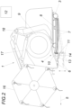
- Fig. 2 shows a cutting unit with a cutting material feed reel 16, the distance from the cutting bar 6 being adjustable by means of a height adjustment 17, wherein the cutting material feed reel 16 is assigned a position sensor 18, and wherein the control 12 controls the height adjustment 17 and thus the cutting material feed reel 16 in such a way that a predetermined minimum distance between the cutting bar 6 and the cutting material feed reel 16 is maintained.
- the height adjustment 17 can consist of one or two hydraulic cylinders connected in series. If two hydraulic cylinders are provided, one takes over the rough adjustment specified by an operator and the other ensures the automatic position correction by means of the control 12.
Landscapes
- Life Sciences & Earth Sciences (AREA)
- Environmental Sciences (AREA)
- Harvester Elements (AREA)
- Combines (AREA)
Description
- Die Erfindung bezieht sich auf ein Schneidwerk für einen Mähdrescher mit einem Tragrahmen für einen Schneidtisch, der schneidseitig einen gelenkig am Rahmen befestigten, quer zur Schnittrichtung flexiblen Schneidbalken aufweist, der mittels mehrerer, über die Schneidwerksbreite verteilt angeordneter, einerends am Schneidbalken und andernends am Rahmen angreifender, Achshebel bezüglich des Rahmens höhenverstellbar ist, wozu den Achshebeln Stelltriebe zwecks Einstellung eines Bodenabstandes zugeordnet sind, wobei die Stelltriebe und damit die Achshebel mit dem Schneidbalken zur Einhaltung eines vorgegebenen Bodenabstandes des Schneidbalkens über die Schneidwerksbreite mit einer Steuerung ansteuerbar sind.
- Ein derartiges Schneidwerk ist beispielsweise aus der
AT 520 625 A2 AT 501 588 A - Die
WO 2019111069 A1 offenbart ein Schneidwerk mit Bandförderern, die Schnittgut vom Schneidwerksrand zur Schneidwerksmitte fördern. Zur Einhaltung eines Bodenabstandes sind mehrere Wiegezellen vorgesehen, welche das Gewicht des auf dem Schneidwerk aufliegenden Schnittgutes messen. Ein Durchhängen des Schneidwerkes in Folge der Auflast kann mit den Stelltrieben kompensiert werden. Ein aktives einstellen eines Bodenabstandes ist nicht vorgesehen. Das Schneidwerk kann über den Boden gleiten und kompensiert die aufruhende Gewichtskraft. Eine ähnliche Vorrichtung ist aus derEP 0160823 A2 bekannt. - Die Aufgabe der Erfindung ist es daher ein Schneidwerk für einen Mähdrescher der eingangs geschilderten Art zu schaffen, das eine schnelle und einfache Anpassung des Schneidbalkens an die jeweils gegebenen Erntebedingungen ermöglicht und dabei für eine annähernd gleichbleibende Schnitthöhe über dem Boden sorgt.
- Die Erfindung löst die gestellte Aufgabe dadurch, dass dem Schneidbalken mehrere über die Schneidwerksbreite verteilt angeordnete, den Bodenabstand des Schneidbalkens aufnehmende Sensoren zugeordnet sind, die in Schnittrichtung vor jedem Achshebel am Schneidbalken vorgesehen sind, wobei die Sensoren bodenseitig am Schneidbalken angeordnete Gleitkufen zur Messung des Bodenanpressdrucks der jeweiligen Gleitkufe oder zur Abstandsmessung zwischen Gleitkufe und Schneidbalken sind.
- Mit dieser Maßnahme ist eine schnelle und einfache Anpassung des Schneidbalkens an die jeweils gegebenen Erntebedingungen möglich, wobei eine annähernd gleichbleibende Schnitthöhe über dem Boden eingehalten werden kann und das über die gesamte Schneidwerksbreite. Ein Aufschieben von Erde infolge zu geringem Bodenabstand während des Erntevorganges kann somit bei unebenen Böden sicher verhindert werden. Die Sensoren sollten naturgemäß möglichst weit vorne am Schneidwerk angeordnet sein. Denkbar sind auch über das Schneidwerk nach vorne abragende Gleitkufen, denen die Sensoren zugeordnet sind. Der quer zur Fahrtrichtung des Mähdreschers flexible Schneidbalken wird erfindungsgemäß somit in erlaubten Bereichen, beispielsweise ± 10-20cm aus einer Neutrallage heraus, aktiv der Kontur der zu mähenden Oberfläche nachgeführt. Die Steuerung, insbesondere ein Fahrzeugcontroller, steuert die Stelltriebe und damit die Achshebel mit dem Schneidbalken derart an, dass ein von einem Bediener vorgegebener Bodenabstand des Schneidbalkens über die Schneidwerksbreite eingehalten wird und vermeidet dabei insbesondere ein Einschneiden des Schneidbalkens in Erdreich.
- Besonders robuste, für den Einsatz an einer Erntemaschine geeignete Sensoren sind bodenseitig am Schneidbalken angeordneten Gleitkufen und messen den Bodenanpressdruck der jeweiligen Gleitkufe mit Wiegezellen oder den Abstand zwischen Gleitkufe und Schneidbalken. Der Anpressdruck einer federnd am Schneidbalken angeordneten Gleitkufe entspricht dem Abstand bzw. lässt sich in den Abstandswert umrechnen.
- Für ein bestmögliches Schnittergebnis und für eine optimale Bodennachführung des Schneidbalkens ist es von Vorteil, dass in Schnittrichtung vor jedem Achshebel je wenigstens ein Sensor am Schneidbalken vorgesehen ist.
- Von besonderem Vorteil ist es, wenn die Achshebel als Gelenkparallelogramme ausgebildet sind, die einerends am Schneidbalken und andernends am Rahmen angreifen. Damit ist der Schneidbalken im Zuge der Bodennachführung stets bodenparallel ausgerichtet und ergibt sich unabhängig vom Bodenabstand ein gleichleibender Schnittwinkel. Zudem wird damit eine Verwindung des Schneidbalkens quer zur Schnittrichtung, um eine Schneidwerkquerachse, vermieden, womit der Schneidwerksverschleiß und die erforderliche Antriebsleistung verringert werden.
- Um der Kontur der zu mähenden Oberfläche sauber folgen zu können und dabei übermäßige Spannungen im Schneidbalken zu vermeiden können die Achshebel über Ausgleichslager mit zur Schnittrichtung paralleler Schwenkachse am Schneidbalken angreifen.
- Robuste und einfach zu wartende Konstruktionsverhältnisse ergeben sich, wenn die die Stelltriebe einerseits am Rahmen und anderseits am Achshebel angreifen.
- Um bei einem Schneidwerk mit einer mit einer Schnittguteinzugshaspel deren Abstand zum Schneidbalken mit einer Höhenverstellung einstellbar ist einen unerwünschten Kontakt mit dem Schneidbalken zu vermeiden, wird vorgeschlagen, dass der Schnittguteinzugshaspel ein Lagesensor zugeordnet ist, und dass mit der Steuerung die Höhenverstellung und damit die Schnittguteinzugshaspel derart ansteuerbar sind, dass ein vorgegebener Mindestabstand zwischen Schneidbalken und Schnittguteinzugshaspel eingehalten ist. Soll eine gegebenenfalls Haspel oder Messer beschädigender Kontakt vermieden werden, ermittelt ein Sensor die jeweilige Position der Haspel und hebt diese bei sich ankündigender Kollision entsprechend an und somit aus dem Gefahrenbereich. Die Höhenverstellung kann aus einem oder aus zwei seriell geschalteten Hydraulikzylindern bestehen. Sind zwei Hydraulikzylinder vorgesehen übernimmt einer die von einem Bediener vorgebbare Grobeinstellung und sorgt der andere mittels der Steuerung für die automatische Lagekorrektur. Damit ist sichergestellt, dass ein Abschneiden von Schnittguteinzugshaspelzinken mit dem Schneidbalken vermieden wird, auch wenn ein Bediener die Haspel durch manuelle Vorgabe maximal möglich am Boden halten will. Die beschriebene Steuerung der Höhenverstellung für die Schnittguteinzugshaspel kann bei jedem bekannten Schneidwerk mit quer zur Schnittrichtung flexiblen Schneidbalken eingesetzt werden.
- Der Tragrahmen mit Schneidbalken und Stelltrieben kann vorzugsweise zwecks Einstellung einer Schneidtischlänge in Schnittrichtung längsverschiebbar an einem die Schnittguteinzugsvorrichtung tragenden Grundrahmen geführt sein.
- Die Stelltriebe werden vorzugsweise insbesondere von Pneumatikzylindern bzw. Pneumatikbälgen gebildet, welche sich einerseits am Tragrahmen abstützen und welche anderseits an einem Achshebel zwischen einem Tragrahmenlager der Achshebel und dem Schneidbalken angreifen. Beidseits der Achshebel können Stelltriebe vorgesehen sein, die über eine die Achshebel überspannende Brücke gekoppelt sind, wobei die Bücke am zugeordneten Achshebel mittels entsprechenden Mitteln angreift.
- Damit ist der Stelltrieb bei geringem Platzbedarf in einen längsverschiebbar am Grundrahmen geführten Tragrahmen integrierbar und ist die Schneidtischlänge zudem innerhalb vorgegebener Grenzen beliebig einstellbar.
- In der Zeichnung ist der Erfindungsgegenstand beispielsweise dargestellt. Es zeigen
- Fig. 1
- Mähdrescher mit einem Schneidwerk in Seitenansicht,
- Fig. 2
- ein erfindungsgemäßes Schneidwerk in teilgeschnittener Seitenansicht,
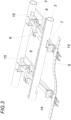
- Fig. 3
- einen vergrößerten Ausschnitt einer Schneidbalkenaufhängung des Schneidwerkes aus
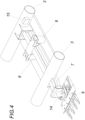
Fig. 2 in Schrägansicht und - Fig. 4
- einen vergrößerten Ausschnitt der Schneidbalkenaufhängung aus
Fig. 3 in Schrägansicht - Ein Schneidwerk 1 für einen Mähdrescher 2 umfasst einen Tragrahmen 3 für einen Schneidtisch 4, der schneidseitig einen gelenkig am Tragrahmen 3 befestigten, quer zur Schnittrichtung 5 flexiblen Schneidbalken 6 aufweist. Der Schneidbalken 6 ist mittels mehrerer, über die Schneidwerksbreite verteilt angeordneter, einerends am Schneidbalken 6 und andernends am Tragrahmen 3 angreifender, Achshebel 7 bezüglich des Tragrahmens 3 höhenverstellbar. Zwecks Einstellung eines Bodenabstandes sind den Achshebeln 7 Stelltriebe 8 zugeordnet mit denen die Höhenlage des Schneidbalkens 6 über die Schneidbalkenbreite variabel bezüglich des Tragrahmens 3 einstellbar ist. Zur Überleitung des Schnittgutes vom Schneidbalken 6 weg zu einer Schnittguteinzugsvorrichtung 9 hin sind entsprechende flexible Übergangsbleche 10 vorgesehen.
- Die Stelltriebe 8 werden insbesondere von Pneumatikzylindern bzw. Pneumatikbälgen gebildet, welche sich einerseits am Tragrahmen 3 abstützen und welche anderseits an einem Achshebel 7 zwischen einem Tragrahmenlager und dem Schneidbalken 6 angreifen. Dazu sind beidseits der Achshebel 7 Stelltriebe 8 vorgesehen, die über eine die Achshebel 7 überspannende Brücke gekoppelt sind, wobei die Bücke am zugeordneten Achshebel 7 angreift. Der Tragrahmen 3 kann mit Schneidbalken 6 und Stelltrieben 8 zwecks Einstellung der Schneidtischlänge in Schnittrichtung längsverschiebbar an einem die Schnittguteinzugsvorrichtung 9 tragenden Grundrahmen geführt sein. Damit ist der Stelltrieb bei geringem Platzbedarf in einen längsverschiebbar am Grundrahmen geführten Tragrahmen 3 integrierbar und ist die Schneidtischlänge zudem innerhalb vorgegebener Grenzen beliebig einstellbar. Im Bereich des Schneidtisches sind dazu einander dachschindelartig überlappende Überleitbleche für das Mähgut vorgesehen, welche den Längenausgleich erlauben.
- Erfindungsgemäß sind dem Schneidbalken 6 mehrere über die Schneidwerksbreite verteilt angeordnete, den Bodenabstand des Schneidbalkens 6 aufnehmende Sensoren 11 zugeordnet. Eine Steuerung 12 steuert die Stelltriebe 8 und damit die Achshebel 7 mit dem Schneidbalken 6 derart an, dass ein vorgegebener Bodenabstand a des Schneidbalkens 6 über die Schneidwerksbreite eingehalten ist.
- Die Sensoren 11, insbesondere Wiegezellen, sind bodenseitig am Schneidbalken 6 angeordnete Gleitkufen 13 und messen den Bodenanpressdruck der jeweiligen Gleitkufe 13 oder messen den Abstand zwischen Gleitkufe 13 und Schneidbalken 6. In Schnittrichtung 5 ist vor jedem Achshebel 7 je wenigstens ein Sensor 11 am Schneidbalken 6 vorgesehen.
- Die Achshebel 7 sind als Gelenkparallelogramme ausgebildet, die einerends am Schneidbalken 6 und andernends am Rahmen 3 angreifen und in entsprechenden Lagerböcken gelagert sind. Zudem greifen die Achshebel 7 über Ausgleichslager 14 mit zur Schnittrichtung 5 paralleler Schwenkachse am Schneidbalken 6 an, der in den Fig. nur sehr schematisch dargestellt ist. Die Stelltriebe 8, beispielsweise Hydraulizylinder, greifen einerseits am Tragrahmen 3 und anderseits am Achshebel 7 an. Mit Lagesensoren 15 kann die Schwenklage der Achshebel 7 erfasst werden.
-
Fig. 2 zeigt ein Schneidwerk mit einer Schnittguteinzugshaspel 16 deren Abstand zum Schneidbalken 6 mit einer Höhenverstellung 17 einstellbar ist, wobei der Schnittguteinzugshaspel 16 ein Lagesensor 18 zugeordnet ist, und wobei die Steuerung 12 die Höhenverstellung 17 und damit die Schnittguteinzugshaspel 16 derart ansteuert, dass ein vorgegebener Mindestabstand zwischen Schneidbalken 6 und Schnittguteinzugshaspel 16 eingehalten ist. Die Höhenverstellung 17 kann aus einem oder aus zwei seriell geschalteten Hydraulikzylindern bestehen. Sind zwei Hydraulikzylinder vorgesehen übernimmt einer die von einem Bediener vorgebbare Grobeinstellung und sorgt der andere mittels der Steuerung 12 für die automatische Lagekorrektur.
Claims (9)
- Schneidwerk (1) für einen Mähdrescher (2) mit einem Tragrahmen (3) für einen Schneidtisch (4), der schneidseitig einen gelenkig am Tragrahmen (3) befestigten, quer zur Schnittrichtung (5) flexiblen Schneidbalken (6) aufweist, der mittels mehrerer, über die Schneidwerksbreite verteilt angeordneter, einerends am Schneidbalken (6) und andernends am Tragrahmen (3) angreifender, Achshebel (7) bezüglich des Tragrahmen (3) höhenverstellbar ist, wozu den Achshebeln (7) Stelltriebe (8) zwecks Einstellung eines Bodenabstandes zugeordnet sind, wobei die Stelltriebe (8) und damit die Achshebel (7) mit dem Schneidbalken (6) zur Einhaltung eines vorgegebenen Bodenabstandes des Schneidbalkens (6) über die Schneidwerksbreite mit einer Steuerung (12) ansteuerbar sind, dadurch gekennzeichnet, dass dem Schneidbalken (6) mehrere über die Schneidwerksbreite verteilt angeordnete, den Bodenabstand des Schneidbalkens (6) aufnehmende Sensoren (11) zugeordnet sind, die in Schnittrichtung (5) vor jedem Achshebel (7) am Schneidbalken (6) vorgesehen sind, wobei die Sensoren (11) bodenseitig am Schneidbalken (6) angeordnete Gleitkufen (13) zur Messung des Bodenanpressdrucks der jeweiligen Gleitkufe (13) oder zur Abstandsmessung zwischen Gleitkufe (13) und Schneidbalken (6) sind.
- Schneidwerk nach Anspruch 1, dadurch gekennzeichnet, dass die Achshebel (7) als Gelenkparallelogramme ausgebildet sind, die einerends am Schneidbalken (6) und andernends am Tragrahmen (3) angreifen.
- Schneidwerk nach Anspruch 1 oder 2, dadurch gekennzeichnet, dass die Achshebel (7) über Ausgleichslager (14) mit zur Schnittrichtung (5) paralleler Schwenkachse am Schneidbalken (6) angreifen.
- Schneidwerk nach einem der Ansprüche 1 bis 3, dadurch gekennzeichnet, dass die Stelltriebe (8) einerseits am Tragrahmen (3) und anderseits am Achshebel (7) angreifen.
- Schneidwerk nach einem der Ansprüche 1 bis 4, mit einer Schnittguteinzugshaspel (16) deren Abstand zum Schneidbalken (6) mit einer Höhenverstellung (17) einstellbar ist, dadurch gekennzeichnet, dass der Schnittguteinzugshaspel (16) ein Lagesensor (18) zugeordnet ist, und dass die Steuerung (12) die Höhenverstellung (17) und damit die Schnittguteinzugshaspel (16) derart ansteuert, dass ein vorgegebener Mindestabstand zwischen Schneidbalken (6) und Schnittguteinzugshaspel (16) eingehalten ist.
- Schneidwerk nach Anspruch 5, dadurch gekennzeichnet, dass die Höhenverstellung (17) aus zwei seriell geschalteten Hydraulikzylindern je Schnittguteinzugshaspelseite bestehen.
- Schneidwerk nach einem der Ansprüche 1 bis 6, dadurch gekennzeichnet, dass der Tragrahmen (3) mit Schneidbalken (6) und Stelltrieben (8) zwecks Einstellung einer Schneidtischlänge in Schnittrichtung längsverschiebbar an einem die Schnittguteinzugsvorrichtung (9) tragenden Grundrahmen geführt ist.
- Schneidwerk nach einem der Ansprüche 1 bis 7, dadurch gekennzeichnet, dass die Stelltriebe (8) insbesondere von Pneumatikzylindern bzw. Pneumatikbälgen gebildet sind, welche sich einerseits am Tragrahmen (3) abstützen und welche anderseits an einem Achshebel (7) zwischen einem Tragrahmenlager der Achshebel (7) und dem Schneidbalken (6) angreifen.
- Schneidwerk nach Anspruch 8, dadurch gekennzeichnet, dass beidseits der Achshebel (7) Stelltriebe (8) vorgesehen sind, die über eine die Achshebel (7) überspannende Brücke gekoppelt sind, wobei die Bücke am zugeordneten Achshebel (7) angreift.
Applications Claiming Priority (2)
| Application Number | Priority Date | Filing Date | Title |
|---|---|---|---|
| ATA50576/2019A AT522856B1 (de) | 2019-06-27 | 2019-06-27 | Schneidwerk für einen Mähdrescher |
| PCT/AT2020/060251 WO2020257838A1 (de) | 2019-06-27 | 2020-06-24 | Schneidwerk für einen mähdrescher |
Publications (3)
| Publication Number | Publication Date |
|---|---|
| EP3989705A1 EP3989705A1 (de) | 2022-05-04 |
| EP3989705C0 EP3989705C0 (de) | 2024-10-16 |
| EP3989705B1 true EP3989705B1 (de) | 2024-10-16 |
Family
ID=71527514
Family Applications (1)
| Application Number | Title | Priority Date | Filing Date |
|---|---|---|---|
| EP20737333.3A Active EP3989705B1 (de) | 2019-06-27 | 2020-06-24 | Schneidwerk für einen mähdrescher |
Country Status (9)
| Country | Link |
|---|---|
| US (1) | US12284943B2 (de) |
| EP (1) | EP3989705B1 (de) |
| JP (1) | JP2022540002A (de) |
| CN (1) | CN114173549A (de) |
| AT (1) | AT522856B1 (de) |
| BR (1) | BR112021026054A2 (de) |
| CA (1) | CA3144501A1 (de) |
| UA (1) | UA129773C2 (de) |
| WO (1) | WO2020257838A1 (de) |
Families Citing this family (4)
| Publication number | Priority date | Publication date | Assignee | Title |
|---|---|---|---|---|
| US11974516B2 (en) * | 2019-12-23 | 2024-05-07 | Cnh Industrial America Llc | Support system for an agricultural header |
| DE102020102596A1 (de) * | 2020-02-03 | 2021-08-05 | Claas Selbstfahrende Erntemaschinen Gmbh | Schneidtischlängenadaption |
| AT527412B1 (de) * | 2023-09-22 | 2025-02-15 | Franz Schrattenecker Ing | Schneidwerk für einen Mähdrescher |
| CN117242978B (zh) * | 2023-11-17 | 2024-01-26 | 山西农业大学 | 一种双链齿式谷物联合收割机割台 |
Family Cites Families (26)
| Publication number | Priority date | Publication date | Assignee | Title |
|---|---|---|---|---|
| GB850299A (en) * | 1957-11-04 | 1960-10-05 | Douglas Raymond Bomford | Improvements in or relating to power operated hedge trimmers |
| US3967437A (en) * | 1975-06-13 | 1976-07-06 | Deere & Company | Indicator for a harvesting platform |
| DE3230330A1 (de) * | 1982-08-14 | 1984-02-16 | Andreas 6303 Hungen Reichhardt | Verfahren und vorrichtung zur steuerung einer schwenkbar an einem fahrzeug befestigten maschinenbaugruppe |
| US4573308A (en) | 1984-04-02 | 1986-03-04 | Deere & Company | Harvesting platform with a floating cutterbar |
| US4776153A (en) * | 1986-02-27 | 1988-10-11 | Deere & Company | Automatic height control for a laterally pivoted harvester header |
| DE3807610A1 (de) * | 1988-03-09 | 1989-09-21 | Claas Ohg | Vorrichtung und verfahren zur lageregelung eines maehwerkes |
| JP3379117B2 (ja) * | 1992-10-28 | 2003-02-17 | 井関農機株式会社 | コンバインにおける穀稈刈取装置 |
| GB9519565D0 (en) | 1995-09-26 | 1995-11-29 | Ford New Holland Nv | Apparatus for controlling a position-adjustable implement |
| AT501588B1 (de) | 2005-11-04 | 2006-10-15 | Schrattenecker Franz Ing | Schneidwerk für einen mähdrescher |
| US20070193243A1 (en) * | 2006-02-10 | 2007-08-23 | Schmidt James R | Combine Harvester Draper Header Having Flexible Cutterbar |
| JP2011200188A (ja) * | 2010-03-26 | 2011-10-13 | Kubota Corp | コンバイン |
| US8051633B2 (en) * | 2010-03-29 | 2011-11-08 | Cnh America Llc | Cutterbar adjustment support for a crop harvesting header |
| US7992374B1 (en) * | 2010-04-06 | 2011-08-09 | Cnh America Llc | Agricultural plant cutting header with fore and aft adjustable flexible cutterbar having automatic preload adjustment |
| US8479483B1 (en) * | 2011-12-27 | 2013-07-09 | Agco Corporation | Flexible draper head providing reduced crop residue accumulation |
| DE102012106065A1 (de) * | 2012-07-06 | 2014-01-09 | Claas Selbstfahrende Erntemaschinen Gmbh | Mähdrescher |
| JP6198543B2 (ja) * | 2013-09-25 | 2017-09-20 | 三菱マヒンドラ農機株式会社 | 汎用コンバイン |
| US20150101300A1 (en) * | 2013-10-15 | 2015-04-16 | Deere & Company | Header Height Sensor |
| JP2016185095A (ja) * | 2015-03-27 | 2016-10-27 | 井関農機株式会社 | コンバインの刈取昇降制御装置 |
| JP6656047B2 (ja) * | 2016-03-29 | 2020-03-04 | ヤンマー株式会社 | コンバイン |
| JP6480885B2 (ja) * | 2016-03-29 | 2019-03-13 | ヤンマー株式会社 | コンバイン |
| US9980431B2 (en) * | 2016-09-12 | 2018-05-29 | Cnh Industrial America Llc | Header height control system with multiple height sensors |
| US10349578B2 (en) * | 2017-02-16 | 2019-07-16 | Cnh Industrial America Llc | Combination flex and rigid header height control in a harvester |
| US10757859B2 (en) * | 2017-07-20 | 2020-09-01 | Deere & Company | System for optimizing platform settings based on crop state classification |
| AT520625A2 (de) * | 2017-11-08 | 2019-05-15 | ||
| HUE057964T2 (hu) * | 2017-12-08 | 2022-06-28 | Agco Corp | Rugalmas aratófej szakaszos magasságszabályzással |
| US11224164B2 (en) * | 2019-04-23 | 2022-01-18 | Deere & Company | Damped float response on an agricultural harvester |
-
2019
- 2019-06-27 AT ATA50576/2019A patent/AT522856B1/de active
-
2020
- 2020-06-24 BR BR112021026054A patent/BR112021026054A2/pt unknown
- 2020-06-24 US US17/622,219 patent/US12284943B2/en active Active
- 2020-06-24 JP JP2021576825A patent/JP2022540002A/ja active Pending
- 2020-06-24 WO PCT/AT2020/060251 patent/WO2020257838A1/de not_active Ceased
- 2020-06-24 CN CN202080054461.0A patent/CN114173549A/zh active Pending
- 2020-06-24 CA CA3144501A patent/CA3144501A1/en active Pending
- 2020-06-24 UA UAA202107581A patent/UA129773C2/uk unknown
- 2020-06-24 EP EP20737333.3A patent/EP3989705B1/de active Active
Also Published As
| Publication number | Publication date |
|---|---|
| CA3144501A1 (en) | 2020-12-30 |
| EP3989705C0 (de) | 2024-10-16 |
| JP2022540002A (ja) | 2022-09-14 |
| AT522856A1 (de) | 2021-02-15 |
| BR112021026054A2 (pt) | 2022-02-08 |
| WO2020257838A1 (de) | 2020-12-30 |
| UA129773C2 (uk) | 2025-07-30 |
| AT522856B1 (de) | 2023-02-15 |
| CN114173549A (zh) | 2022-03-11 |
| EP3989705A1 (de) | 2022-05-04 |
| US20220346316A1 (en) | 2022-11-03 |
| US12284943B2 (en) | 2025-04-29 |
Similar Documents
| Publication | Publication Date | Title |
|---|---|---|
| EP3989705B1 (de) | Schneidwerk für einen mähdrescher | |
| EP0958730B1 (de) | Einrichtung zur Steuerung und Einstellung von Arbeitszylindern | |
| EP3335541B1 (de) | Verfahren zum betreiben eines schneidwerks | |
| EP3549433A1 (de) | Höhensteuerungssystem für ein erntevorsatzgerät | |
| EP2517542B1 (de) | Bodenbearbeitungsgerät mit Einebnungsteil | |
| EP0234585A2 (de) | Mähdrescher | |
| EP2529614B1 (de) | Mähwerkskombination | |
| EP4147563A1 (de) | Selbstfahrende erntemaschine mit einer höhenverstellbaren aufnahmevorrichtung | |
| EP4162789B1 (de) | Verfahren zum betreiben eines an einer aufnahmevorrichtung eines selbstfahrenden mähdreschers angeordneten vorsatzgerätes sowie selbstfahrender mähdrescher mit einem segmentierten vorsatzgerät | |
| EP3704928A1 (de) | Erntemaschine sowie verfahren zur ernte mittels einer erntemaschine | |
| DE102005055983A1 (de) | Zuführeinrichtung für einen Feldhäcksler | |
| DE2014807B2 (de) | Vorrichtung zur selbsttaetigen regelung der fahrgeschwindigkeit selbstfahrender maehdrescher | |
| DE3213848C2 (de) | ||
| DE102017214354B3 (de) | Landwirtschaftliches Arbeitsfahrzeug mit Bodeneingriffsmitteln zur Übertragung von Querkräften | |
| EP3243372B1 (de) | Verfahren zum einstellen eines schnittwinkels eines an einer selbstfahrenden erntemaschine angeordneten vorsatzgerätes | |
| EP4030886B1 (de) | Schneidwerk mit höhenelastisch gelagerten schneidelementen | |
| EP0363916B1 (de) | Vorrichtung zum Ernten von Feldfrüchten, insbesondere Rüben | |
| EP3092887B1 (de) | Heuwerbungsmaschine | |
| EP4056021B1 (de) | Schneidwerk | |
| EP4049527B1 (de) | Bandschneidwerk | |
| DE3937124A1 (de) | Mit profilbandlaufwerken arbeitendes mehrzweckfahrzeug | |
| EP3022997A1 (de) | Landwirtschaftliche bodenbearbeitungsvorrichtung | |
| DE102018215263A1 (de) | Selbstfahrende Erntemaschine mit einer Überladeeinrichtung | |
| DE202004011193U1 (de) | Höheneinstellvorrichtung an einer Aufnahmetrommel | |
| EP4646915A1 (de) | Verfahren zum betreiben eines an einer aufnahmevorrichtung eines mähdreschers angeordneten vorsatzgerätes sowie selbstfahrender mähdrescher |
Legal Events
| Date | Code | Title | Description |
|---|---|---|---|
| STAA | Information on the status of an ep patent application or granted ep patent |
Free format text: STATUS: UNKNOWN |
|
| STAA | Information on the status of an ep patent application or granted ep patent |
Free format text: STATUS: THE INTERNATIONAL PUBLICATION HAS BEEN MADE |
|
| PUAI | Public reference made under article 153(3) epc to a published international application that has entered the european phase |
Free format text: ORIGINAL CODE: 0009012 |
|
| STAA | Information on the status of an ep patent application or granted ep patent |
Free format text: STATUS: REQUEST FOR EXAMINATION WAS MADE |
|
| 17P | Request for examination filed |
Effective date: 20211215 |
|
| AK | Designated contracting states |
Kind code of ref document: A1 Designated state(s): AL AT BE BG CH CY CZ DE DK EE ES FI FR GB GR HR HU IE IS IT LI LT LU LV MC MK MT NL NO PL PT RO RS SE SI SK SM TR |
|
| DAV | Request for validation of the european patent (deleted) | ||
| DAX | Request for extension of the european patent (deleted) | ||
| GRAP | Despatch of communication of intention to grant a patent |
Free format text: ORIGINAL CODE: EPIDOSNIGR1 |
|
| STAA | Information on the status of an ep patent application or granted ep patent |
Free format text: STATUS: GRANT OF PATENT IS INTENDED |
|
| INTG | Intention to grant announced |
Effective date: 20240328 |
|
| GRAS | Grant fee paid |
Free format text: ORIGINAL CODE: EPIDOSNIGR3 |
|
| GRAA | (expected) grant |
Free format text: ORIGINAL CODE: 0009210 |
|
| STAA | Information on the status of an ep patent application or granted ep patent |
Free format text: STATUS: THE PATENT HAS BEEN GRANTED |
|
| AK | Designated contracting states |
Kind code of ref document: B1 Designated state(s): AL AT BE BG CH CY CZ DE DK EE ES FI FR GB GR HR HU IE IS IT LI LT LU LV MC MK MT NL NO PL PT RO RS SE SI SK SM TR |
|
| REG | Reference to a national code |
Ref country code: GB Ref legal event code: FG4D Free format text: NOT ENGLISH |
|
| REG | Reference to a national code |
Ref country code: CH Ref legal event code: EP |
|
| REG | Reference to a national code |
Ref country code: IE Ref legal event code: FG4D Free format text: LANGUAGE OF EP DOCUMENT: GERMAN |
|
| REG | Reference to a national code |
Ref country code: DE Ref legal event code: R096 Ref document number: 502020009511 Country of ref document: DE |
|
| U01 | Request for unitary effect filed |
Effective date: 20241107 |
|
| U07 | Unitary effect registered |
Designated state(s): AT BE BG DE DK EE FI FR IT LT LU LV MT NL PT RO SE SI Effective date: 20241115 |
|
| PG25 | Lapsed in a contracting state [announced via postgrant information from national office to epo] |
Ref country code: HR Free format text: LAPSE BECAUSE OF FAILURE TO SUBMIT A TRANSLATION OF THE DESCRIPTION OR TO PAY THE FEE WITHIN THE PRESCRIBED TIME-LIMIT Effective date: 20241016 Ref country code: IS Free format text: LAPSE BECAUSE OF FAILURE TO SUBMIT A TRANSLATION OF THE DESCRIPTION OR TO PAY THE FEE WITHIN THE PRESCRIBED TIME-LIMIT Effective date: 20250216 |
|
| PG25 | Lapsed in a contracting state [announced via postgrant information from national office to epo] |
Ref country code: ES Free format text: LAPSE BECAUSE OF FAILURE TO SUBMIT A TRANSLATION OF THE DESCRIPTION OR TO PAY THE FEE WITHIN THE PRESCRIBED TIME-LIMIT Effective date: 20241016 |
|
| PG25 | Lapsed in a contracting state [announced via postgrant information from national office to epo] |
Ref country code: NO Free format text: LAPSE BECAUSE OF FAILURE TO SUBMIT A TRANSLATION OF THE DESCRIPTION OR TO PAY THE FEE WITHIN THE PRESCRIBED TIME-LIMIT Effective date: 20250116 |
|
| PG25 | Lapsed in a contracting state [announced via postgrant information from national office to epo] |
Ref country code: GR Free format text: LAPSE BECAUSE OF FAILURE TO SUBMIT A TRANSLATION OF THE DESCRIPTION OR TO PAY THE FEE WITHIN THE PRESCRIBED TIME-LIMIT Effective date: 20250117 |
|
| PG25 | Lapsed in a contracting state [announced via postgrant information from national office to epo] |
Ref country code: PL Free format text: LAPSE BECAUSE OF FAILURE TO SUBMIT A TRANSLATION OF THE DESCRIPTION OR TO PAY THE FEE WITHIN THE PRESCRIBED TIME-LIMIT Effective date: 20241016 |
|
| PG25 | Lapsed in a contracting state [announced via postgrant information from national office to epo] |
Ref country code: RS Free format text: LAPSE BECAUSE OF FAILURE TO SUBMIT A TRANSLATION OF THE DESCRIPTION OR TO PAY THE FEE WITHIN THE PRESCRIBED TIME-LIMIT Effective date: 20250116 |
|
| PG25 | Lapsed in a contracting state [announced via postgrant information from national office to epo] |
Ref country code: SM Free format text: LAPSE BECAUSE OF FAILURE TO SUBMIT A TRANSLATION OF THE DESCRIPTION OR TO PAY THE FEE WITHIN THE PRESCRIBED TIME-LIMIT Effective date: 20241016 |
|
| PG25 | Lapsed in a contracting state [announced via postgrant information from national office to epo] |
Ref country code: SK Free format text: LAPSE BECAUSE OF FAILURE TO SUBMIT A TRANSLATION OF THE DESCRIPTION OR TO PAY THE FEE WITHIN THE PRESCRIBED TIME-LIMIT Effective date: 20241016 |
|
| PG25 | Lapsed in a contracting state [announced via postgrant information from national office to epo] |
Ref country code: CZ Free format text: LAPSE BECAUSE OF FAILURE TO SUBMIT A TRANSLATION OF THE DESCRIPTION OR TO PAY THE FEE WITHIN THE PRESCRIBED TIME-LIMIT Effective date: 20241016 |
|
| U20 | Renewal fee for the european patent with unitary effect paid |
Year of fee payment: 6 Effective date: 20250625 |
|
| PLBE | No opposition filed within time limit |
Free format text: ORIGINAL CODE: 0009261 |
|
| STAA | Information on the status of an ep patent application or granted ep patent |
Free format text: STATUS: NO OPPOSITION FILED WITHIN TIME LIMIT |
|
| 26N | No opposition filed |
Effective date: 20250717 |