EP3989199A1 - Procédé de commande et système de commande pour véhicule - Google Patents
Procédé de commande et système de commande pour véhicule Download PDFInfo
- Publication number
- EP3989199A1 EP3989199A1 EP20826872.2A EP20826872A EP3989199A1 EP 3989199 A1 EP3989199 A1 EP 3989199A1 EP 20826872 A EP20826872 A EP 20826872A EP 3989199 A1 EP3989199 A1 EP 3989199A1
- Authority
- EP
- European Patent Office
- Prior art keywords
- vehicle
- subject
- point
- route
- magnetic
- Prior art date
- Legal status (The legal status is an assumption and is not a legal conclusion. Google has not performed a legal analysis and makes no representation as to the accuracy of the status listed.)
- Pending
Links
- 238000000034 method Methods 0.000 title claims description 75
- 238000012545 processing Methods 0.000 claims abstract description 25
- 230000008569 process Effects 0.000 claims description 51
- 238000012937 correction Methods 0.000 claims description 40
- 230000008859 change Effects 0.000 claims description 7
- 239000003550 marker Substances 0.000 description 64
- 238000001514 detection method Methods 0.000 description 22
- 238000010586 diagram Methods 0.000 description 16
- 238000005259 measurement Methods 0.000 description 16
- 230000004907 flux Effects 0.000 description 9
- 230000005389 magnetism Effects 0.000 description 5
- UQSXHKLRYXJYBZ-UHFFFAOYSA-N Iron oxide Chemical compound [Fe]=O UQSXHKLRYXJYBZ-UHFFFAOYSA-N 0.000 description 4
- 238000006073 displacement reaction Methods 0.000 description 4
- 230000001133 acceleration Effects 0.000 description 3
- 230000000694 effects Effects 0.000 description 3
- 238000005516 engineering process Methods 0.000 description 3
- 230000002349 favourable effect Effects 0.000 description 3
- 230000006870 function Effects 0.000 description 3
- 230000010354 integration Effects 0.000 description 3
- 239000011295 pitch Substances 0.000 description 3
- 239000006247 magnetic powder Substances 0.000 description 2
- 239000004033 plastic Substances 0.000 description 2
- 229920003023 plastic Polymers 0.000 description 2
- 229920000139 polyethylene terephthalate Polymers 0.000 description 2
- 239000005020 polyethylene terephthalate Substances 0.000 description 2
- 239000002861 polymer material Substances 0.000 description 2
- 239000000758 substrate Substances 0.000 description 2
- 229910000859 α-Fe Inorganic materials 0.000 description 2
- -1 Polyethylene terephthalate Polymers 0.000 description 1
- 230000005540 biological transmission Effects 0.000 description 1
- 238000004891 communication Methods 0.000 description 1
- 230000004069 differentiation Effects 0.000 description 1
- 230000005674 electromagnetic induction Effects 0.000 description 1
- 239000000696 magnetic material Substances 0.000 description 1
- 238000013507 mapping Methods 0.000 description 1
- 239000000463 material Substances 0.000 description 1
- 230000002093 peripheral effect Effects 0.000 description 1
- 230000004044 response Effects 0.000 description 1
- 238000005070 sampling Methods 0.000 description 1
- 230000035945 sensitivity Effects 0.000 description 1
- 230000002123 temporal effect Effects 0.000 description 1
Images


Classifications
-
- B—PERFORMING OPERATIONS; TRANSPORTING
- B62—LAND VEHICLES FOR TRAVELLING OTHERWISE THAN ON RAILS
- B62D—MOTOR VEHICLES; TRAILERS
- B62D15/00—Steering not otherwise provided for
- B62D15/02—Steering position indicators ; Steering position determination; Steering aids
- B62D15/025—Active steering aids, e.g. helping the driver by actively influencing the steering system after environment evaluation
- B62D15/0265—Automatic obstacle avoidance by steering
-
- B—PERFORMING OPERATIONS; TRANSPORTING
- B60—VEHICLES IN GENERAL
- B60W—CONJOINT CONTROL OF VEHICLE SUB-UNITS OF DIFFERENT TYPE OR DIFFERENT FUNCTION; CONTROL SYSTEMS SPECIALLY ADAPTED FOR HYBRID VEHICLES; ROAD VEHICLE DRIVE CONTROL SYSTEMS FOR PURPOSES NOT RELATED TO THE CONTROL OF A PARTICULAR SUB-UNIT
- B60W60/00—Drive control systems specially adapted for autonomous road vehicles
- B60W60/001—Planning or execution of driving tasks
-
- B—PERFORMING OPERATIONS; TRANSPORTING
- B60—VEHICLES IN GENERAL
- B60W—CONJOINT CONTROL OF VEHICLE SUB-UNITS OF DIFFERENT TYPE OR DIFFERENT FUNCTION; CONTROL SYSTEMS SPECIALLY ADAPTED FOR HYBRID VEHICLES; ROAD VEHICLE DRIVE CONTROL SYSTEMS FOR PURPOSES NOT RELATED TO THE CONTROL OF A PARTICULAR SUB-UNIT
- B60W30/00—Purposes of road vehicle drive control systems not related to the control of a particular sub-unit, e.g. of systems using conjoint control of vehicle sub-units
- B60W30/08—Active safety systems predicting or avoiding probable or impending collision or attempting to minimise its consequences
- B60W30/09—Taking automatic action to avoid collision, e.g. braking and steering
-
- B—PERFORMING OPERATIONS; TRANSPORTING
- B60—VEHICLES IN GENERAL
- B60W—CONJOINT CONTROL OF VEHICLE SUB-UNITS OF DIFFERENT TYPE OR DIFFERENT FUNCTION; CONTROL SYSTEMS SPECIALLY ADAPTED FOR HYBRID VEHICLES; ROAD VEHICLE DRIVE CONTROL SYSTEMS FOR PURPOSES NOT RELATED TO THE CONTROL OF A PARTICULAR SUB-UNIT
- B60W30/00—Purposes of road vehicle drive control systems not related to the control of a particular sub-unit, e.g. of systems using conjoint control of vehicle sub-units
- B60W30/10—Path keeping
- B60W30/12—Lane keeping
-
- B—PERFORMING OPERATIONS; TRANSPORTING
- B60—VEHICLES IN GENERAL
- B60W—CONJOINT CONTROL OF VEHICLE SUB-UNITS OF DIFFERENT TYPE OR DIFFERENT FUNCTION; CONTROL SYSTEMS SPECIALLY ADAPTED FOR HYBRID VEHICLES; ROAD VEHICLE DRIVE CONTROL SYSTEMS FOR PURPOSES NOT RELATED TO THE CONTROL OF A PARTICULAR SUB-UNIT
- B60W30/00—Purposes of road vehicle drive control systems not related to the control of a particular sub-unit, e.g. of systems using conjoint control of vehicle sub-units
- B60W30/18—Propelling the vehicle
- B60W30/18009—Propelling the vehicle related to particular drive situations
- B60W30/18163—Lane change; Overtaking manoeuvres
-
- B—PERFORMING OPERATIONS; TRANSPORTING
- B62—LAND VEHICLES FOR TRAVELLING OTHERWISE THAN ON RAILS
- B62D—MOTOR VEHICLES; TRAILERS
- B62D15/00—Steering not otherwise provided for
- B62D15/02—Steering position indicators ; Steering position determination; Steering aids
- B62D15/025—Active steering aids, e.g. helping the driver by actively influencing the steering system after environment evaluation
- B62D15/0255—Automatic changing of lane, e.g. for passing another vehicle
-
- G—PHYSICS
- G01—MEASURING; TESTING
- G01C—MEASURING DISTANCES, LEVELS OR BEARINGS; SURVEYING; NAVIGATION; GYROSCOPIC INSTRUMENTS; PHOTOGRAMMETRY OR VIDEOGRAMMETRY
- G01C21/00—Navigation; Navigational instruments not provided for in groups G01C1/00 - G01C19/00
- G01C21/10—Navigation; Navigational instruments not provided for in groups G01C1/00 - G01C19/00 by using measurements of speed or acceleration
- G01C21/12—Navigation; Navigational instruments not provided for in groups G01C1/00 - G01C19/00 by using measurements of speed or acceleration executed aboard the object being navigated; Dead reckoning
- G01C21/16—Navigation; Navigational instruments not provided for in groups G01C1/00 - G01C19/00 by using measurements of speed or acceleration executed aboard the object being navigated; Dead reckoning by integrating acceleration or speed, i.e. inertial navigation
- G01C21/165—Navigation; Navigational instruments not provided for in groups G01C1/00 - G01C19/00 by using measurements of speed or acceleration executed aboard the object being navigated; Dead reckoning by integrating acceleration or speed, i.e. inertial navigation combined with non-inertial navigation instruments
-
- G—PHYSICS
- G05—CONTROLLING; REGULATING
- G05D—SYSTEMS FOR CONTROLLING OR REGULATING NON-ELECTRIC VARIABLES
- G05D1/00—Control of position, course, altitude or attitude of land, water, air or space vehicles, e.g. using automatic pilots
- G05D1/02—Control of position or course in two dimensions
- G05D1/021—Control of position or course in two dimensions specially adapted to land vehicles
- G05D1/0259—Control of position or course in two dimensions specially adapted to land vehicles using magnetic or electromagnetic means
-
- B—PERFORMING OPERATIONS; TRANSPORTING
- B60—VEHICLES IN GENERAL
- B60W—CONJOINT CONTROL OF VEHICLE SUB-UNITS OF DIFFERENT TYPE OR DIFFERENT FUNCTION; CONTROL SYSTEMS SPECIALLY ADAPTED FOR HYBRID VEHICLES; ROAD VEHICLE DRIVE CONTROL SYSTEMS FOR PURPOSES NOT RELATED TO THE CONTROL OF A PARTICULAR SUB-UNIT
- B60W2552/00—Input parameters relating to infrastructure
- B60W2552/05—Type of road, e.g. motorways, local streets, paved or unpaved roads
-
- B—PERFORMING OPERATIONS; TRANSPORTING
- B60—VEHICLES IN GENERAL
- B60W—CONJOINT CONTROL OF VEHICLE SUB-UNITS OF DIFFERENT TYPE OR DIFFERENT FUNCTION; CONTROL SYSTEMS SPECIALLY ADAPTED FOR HYBRID VEHICLES; ROAD VEHICLE DRIVE CONTROL SYSTEMS FOR PURPOSES NOT RELATED TO THE CONTROL OF A PARTICULAR SUB-UNIT
- B60W2552/00—Input parameters relating to infrastructure
- B60W2552/30—Road curve radius
-
- B—PERFORMING OPERATIONS; TRANSPORTING
- B62—LAND VEHICLES FOR TRAVELLING OTHERWISE THAN ON RAILS
- B62D—MOTOR VEHICLES; TRAILERS
- B62D15/00—Steering not otherwise provided for
- B62D15/02—Steering position indicators ; Steering position determination; Steering aids
- B62D15/025—Active steering aids, e.g. helping the driver by actively influencing the steering system after environment evaluation
-
- G—PHYSICS
- G01—MEASURING; TESTING
- G01C—MEASURING DISTANCES, LEVELS OR BEARINGS; SURVEYING; NAVIGATION; GYROSCOPIC INSTRUMENTS; PHOTOGRAMMETRY OR VIDEOGRAMMETRY
- G01C21/00—Navigation; Navigational instruments not provided for in groups G01C1/00 - G01C19/00
- G01C21/26—Navigation; Navigational instruments not provided for in groups G01C1/00 - G01C19/00 specially adapted for navigation in a road network
- G01C21/34—Route searching; Route guidance
- G01C21/3407—Route searching; Route guidance specially adapted for specific applications
-
- G—PHYSICS
- G01—MEASURING; TESTING
- G01V—GEOPHYSICS; GRAVITATIONAL MEASUREMENTS; DETECTING MASSES OR OBJECTS; TAGS
- G01V3/00—Electric or magnetic prospecting or detecting; Measuring magnetic field characteristics of the earth, e.g. declination, deviation
- G01V3/08—Electric or magnetic prospecting or detecting; Measuring magnetic field characteristics of the earth, e.g. declination, deviation operating with magnetic or electric fields produced or modified by objects or geological structures or by detecting devices
- G01V3/081—Electric or magnetic prospecting or detecting; Measuring magnetic field characteristics of the earth, e.g. declination, deviation operating with magnetic or electric fields produced or modified by objects or geological structures or by detecting devices the magnetic field is produced by the objects or geological structures
-
- G—PHYSICS
- G08—SIGNALLING
- G08G—TRAFFIC CONTROL SYSTEMS
- G08G1/00—Traffic control systems for road vehicles
- G08G1/01—Detecting movement of traffic to be counted or controlled
- G08G1/042—Detecting movement of traffic to be counted or controlled using inductive or magnetic detectors
Definitions
- the present invention relates to a control method and control system for letting a vehicle travel by automatic steering.
- a car navigation system has been known in which, for example, GPS waves are received to measure a vehicle position and the vehicle is guided to a destination set in advance (refer to, for example, Patent Literature 1 mentioned below).
- driving assist control such as voice output for guiding a route, it is possible to efficiently arrive at the destination without losing the route even during movement in an unfamiliar area.
- a driving assist system using 3D map data which three-dimensionally represents a road environment including peripheral environments such as surrounding buildings, guardrails, signs, and curbs.
- this driving assist system for example, by mapping an own vehicle position on the 3D map data, it is possible to achieve sophisticated driving assist including automatic driving. If automatic driving becomes possible, load of driving the vehicle can be reduced.
- Patent Literature 1 Japanese Unexamined Patent Application Publication No. 2001-264076
- the present invention was made in view of the above-described conventional problems, and is to provide a highly-versatile automatic-steering control method and control system.
- One mode of the present invention resides in a vehicular control method for letting a vehicle travel by automatic steering, the control method executing:
- One mode of the present invention resides in a vehicular control system for letting a vehicle travel by automatic steering, the control system including:
- the vehicle control method and control system according to the present invention are a control method and so forth which let the vehicle travel by automatic steering so that the subject point set for the vehicle passes through the predetermined route.
- the present invention has one of technical features in selecting the new subject point set as the subject point as the control subject and updating the subject point.
- control method and so forth according to the present invention by updating the subject point as a control subject, the route where the vehicle actually travels can be adjusted.
- the control method and control system according to the present invention are highly-versatile control method and control system which can adjust the traveling route of the vehicle without greatly changing the control specifications.
- the present embodiment is an example regarding a control method and control system for letting vehicle 5 travel along a target route set in advance (one example of a predetermined route) . Details of this are described by using FIG. 1 to FIG. 19 .
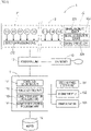
- Automatic driving system 1 as one example of a control system is configured to include, as in FIG. 1 , sensor unit 2 which performs magnetic detection and so forth, tag reader 13 which obtains marker position information indicating a laying position of magnetic marker 30, positioning unit 12 which identifies an own vehicle position, traveling control unit 11 which controls traveling of vehicle 5, and so forth.
- Traveling control unit 11 can refer to a storage area of map database (map DB) 110 which stores detailed three-dimensional map data (3D map data).
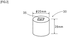
- Magnetic marker 30 is, as in FIG. 1 and FIG. 2 , a road marker to be laid in road surface 300S of the road. Magnetic markers 30 are arranged along the center of a lane (sign 300 in FIG. 8 , traveling road) sectioned by left and right lane marks with pitches of, for example, 10 meters.
- the magnetic marker 30 has a columnar shape having a diameter of 20 mm and a height of 28 mm. This magnetic marker 30 is laid in a state of being accommodated in a hole provided in road surface 300S.
- a magnet forming magnetic marker 30 is a ferrite plastic magnet with magnetic powder of iron oxide as a magnetic material dispersed in a polymer material as a base material. The maximum energy product (BHmax) of this magnet is 6.4 kJ/square m.
- Magnetic marker 30 of the present embodiment are partially depicted in Table 1.
- Table 1 Type of magnet Ferrite plastic magnet Diameter ⁇ 20 mm Height 28 mm Magnetic flux density Gs at the surface 45 mT
- Magnetic marker 30 acts with magnetism of a magnetic flux density of 8 ⁇ T (microtesla) at an upper-limit height of 250 mm in a range from 100 mm to 250 mm assumed as an attachment height of sensor unit 2. Also, in this magnetic marker 30, a magnetic flux density Gs of the surface indicating a magnetic strength on the surface is 45 mT.
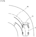
- RFID (Radio Frequency IDentification) tag 35 which wirelessly outputs information is attached to an end face serving as an upper surface.
- RFID tag 35 operates by wireless external power feeding and transmits position data, which is marker position information indicating the laying position of magnetic marker 30.
- magnetic marker 30 is the magnet with magnetic powder of iron oxide dispersed in the polymer material. This magnet has low conductivity and is hard to cause eddy current or the like at the time of wireless power feeding. Therefore, RFID tag 35 annexed to magnetic marker 30 can efficiently receive wirelessly-transmitted power.
- RFID tag 35 is an electronic component having IC chip 357 implemented on a surface of tag sheet 350 ( FIG. 3 ) cut out from, for example, a PET (Polyethylene terephthalate) film.
- IC chip 357 implemented on a surface of tag sheet 350 ( FIG. 3 ) cut out from, for example, a PET (Polyethylene terephthalate) film.
- a printed pattern of loop coil 351 is provided on the surface of tag sheet 350.
- Loop coil 351 achieves a function as a receiving coil to generate an exciting current by external electromagnetic induction and a function as a transmission antenna for wirelessly transmitting position data and so forth.
- Sensor unit 2 is, as in FIG. 1 and FIG. 4 , a rod-shaped unit having magnetic sensor array 21 as a magnetic detecting part and IMU (Inertial Measurement Unit) 22 for use in inertial navigation integrated together.
- Sensor unit 2 is attached so as to face road surface 300S in a state of being along a vehicle-width direction.
- Sensor unit 2 attached to, for example, the inside of a front bumper of vehicle 5 or the like, has an attachment height of 200 mm with reference to road surface 300S.
- Magnetic sensor array 21 ( FIG. 4 ) includes fifteen magnetic sensors Cn (n is an integer of 1 to 15) arrayed on one straight line and detection processing circuit 212 having a CPU and so forth not depicted incorporated therein.
- fifteen magnetic sensors Cn configuring magnetic sensor array 21 are arrayed with 10-centimeter pitches along a longitudinal direction.
- magnetic sensor C1 is positioned on the left side (driver's seat side in a left-hand vehicle) of vehicle 5
- magnetic sensor C15 is positioned on the right side (passenger's seat side) of vehicle 5 (refer to FIG. 10 ) .
- Magnetic sensors Cn are sensors which detect magnetism by using the known MI effect (Magnet Impedance Effect) in which impedance of a magneto-sensitive body such as an amorphous wire sensitively changes in response to an external magnetic field. Magnetic sensors Cn have magnetic sensitivity in the longitudinal direction of the amorphous wire.
- magneto-sensitive bodies such as amorphous wires are arranged along two orthogonal axial directions. According to magnetic sensors Cn, magnetism acting on the two orthogonal axial directions can be detected. Note that in sensor unit 2 of the present embodiment, magnetic sensors Cn are incorporated so as to be able to detect magnetic components in a forwarding direction and the vehicle-width direction in a state of being attached to vehicle 5.
- Magnetic sensors Cn are highly-sensitive sensors having a measurement range of the magnetic flux density of ⁇ 0.6 mT and a magnetic flux resolution of 0.02 ⁇ T within the measurement range.
- a frequency of magnetic measurement by each magnetic sensor Cn of sensor unit 2 is set at 3 kHz so as to support high-speed vehicle traveling.
- magnetic marker 30 can act with magnetism having the magnetic flux density equal to or larger than 8 ⁇ T in the range from 100 mm to 250 mm assumed as the attachment height of magnetic sensors Cn. Magnetic marker 30 acting with magnetism having the magnetic flux density equal to or larger than 8 ⁇ T can be detected with high reliability by using magnetic sensors Cn having the magnetic flux resolution of 0.02 ⁇ T.
- Detection processing circuit 212 ( FIG. 4 ) of magnetic sensor array 21 is an arithmetic circuit which performs marker detection process for detecting magnetic marker 30 ( FIG. 1 ).
- This detection processing circuit 212 is configured by using a CPU (central processing unit) which performs various calculations, memory elements such as a ROM (read only memory) and a RAM (random access memory), and so forth.
- Detection processing circuit 212 obtains a sensor signal outputted from each of magnetic sensors Cn at the frequency of 3 kHz to perform marker detection process. Detection processing circuit 212 inputs detection result of the marker detection process to positioning unit 12. Although details will be described further below, in this marker detection process, in addition to detection of magnetic marker 30, measurement of a lateral shift amount of a subject point of vehicle 5 with respect to magnetic marker 30 is performed.
- IMU 22 ( FIG. 4 ) is an inertial navigation unit which estimates a relative position of vehicle 5 by inertial navigation.
- IMU 22 includes biaxial magnetic sensor 221 as an electronic compass which measures an azimuth, biaxial acceleration sensor 222 which measures acceleration, and biaxial gyro sensor 223 which measures angular velocity about a yaw axis.
- the yaw axis is an axis in a vertical direction.
- IMU 22 calculates a displacement amount by double integration of measured acceleration, and also calculates the azimuth of vehicle 5 by integration of measured angular velocity. The displacement amount and azimuth obtained by IMU 22 by calculation is inputted to positioning unit 12.
- Tag reader 13 ( FIG. 4 ) is a communication unit which wirelessly communicates with RFID tag 35 attached at the end face of magnetic marker 30.
- Tag reader 13 wirelessly transmits electric power required for operation of RFID tag 35, and receives position data transmitted from RFID tag 35.
- This position data which is one example of marker position information, is data indicating the laying position (absolute position) of corresponding magnetic marker 30.
- Positioning unit 12 ( FIG. 4 ) is a unit which controls sensor unit 2 and tag reader 13 and identifies the own vehicle position, which is the position of a subject point set with respect to vehicle 5 (which is referred to as a subject point of the vehicle, as appropriate) in real time. Positioning unit 12 inputs the own vehicle position to traveling control unit 11 which controls traveling of vehicle 5.
- Positioning unit 12 includes an electronic substrate (omitted in the drawing) having implemented thereon a CPU which performs various computations, memory elements such as a ROM and a RAM, and so forth.
- a method of identifying the own vehicle position by positioning unit 12 varies depending on a case when vehicle 5 reaches magnetic marker 30 or a case when vehicle 5 is positioned in an intermediate position between adjacent magnetic markers 30.
- positioning unit 12 estimates the own vehicle position based on the position data (marker position information) received from RFID tag 35.
- the own vehicle position is identified based on the relative position of vehicle 5 estimated by inertial navigation.
- Traveling control unit 11 ( FIG. 4 ) is a unit which controls vehicle 5 to achieve automatic driving to, for example, a destination set by a driver.
- Traveling control unit 11 includes route data generating part 111 which generates route data indicating the target route, vehicle control part 112 which control vehicle 5, subject-point selection processing part 113 which selects a subject point to be set with respect to vehicle 5, and subject-point updating processing part 114 which updates a subject point as a control subject.
- map database (map DB) 110 having stored therein detailed three-dimensional map data (3D map data) is connected. Furthermore, what are controllably connected in to traveling control unit 11 are steering unit 151, engine throttle 152, brake actuator 153, and so forth.
- Traveling control unit 11 includes an electronic substrate having implemented thereon a CPU, memory devices such as a ROM and a RAM, an I/O chip for external input/output, and so forth not depicted. For example, with the CPU executing a program read from the ROM, traveling control unit 11 achieves functions as respective parts 111 to 114 described above. Also, in a storage area of the ROM, data regarding vehicle specifications is stored, such as the vehicle width, which is a lateral-width dimension of vehicle 5; a wheel base, which is an interaxial distance between a front-wheel axis and a rear-wheel axis.
- the marker detection process is a process to be performed by magnetic sensor array 21.
- Magnetic sensor array 21 performs, as described above, marker detection process at the frequency of 3 kHz by using magnetic sensors Cn.
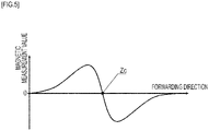
- magnetic sensors Cn can measure magnetic components in the forwarding direction and the vehicle-width direction of vehicle 5. For example, when these magnetic sensors Cn move in the forwarding direction to pass directly above magnetic marker 30, the magnetic measurement value in the forwarding direction has its sign reversed before and after passing magnetic marker 30 as in FIG. 5 and temporally changes so as to cross zero at a position directly above magnetic marker 30.
- sensor unit 2 magnetic sensor array 21
- Detection processing circuit 212 determines that magnetic marker 30 is detected when sensor unit 2 is positioned directly above magnetic marker 30 and zero-cross of the magnetic measurement value in the forwarding direction occurs as described above.
- the magnetic measurement value in the vehicle-width direction has its sign reversed on both sides across magnetic marker 30 and changes so as to cross zero at a position directly above magnetic marker 30. Therefore, in the case of magnetic sensor array 21 having fifteen magnetic sensors Cn arrayed in the vehicle-width direction, the sign of the magnetic measurement value in the vehicle-width direction to be detected by magnetic sensor Cn varies depending on which side the magnetic sensor is present with respect to magnetic marker 30 ( FIG. 6 ).
- FIG. 6 exemplarily depicting magnetic measurement values in the vehicle-width direction of each of magnetic sensors Cn
- zero-cross Zc where the sign of the magnetic measurement value in the vehicle-width direction is reversed appears so as to correspond to magnetic marker 30.
- the position of zero-cross Zc in the distribution of the drawing represents the position of magnetic marker 30 in the vehicle-width direction.
- the position of magnetic marker 30 in the vehicle-width direction can be identified as, for example, an intermediate position between adjacent two magnetic sensors Cn across zero-cross Zc or a position directly below magnetic sensor Cn in which its magnetic measurement value in the vehicle-width direction is zero and the signs of magnetic sensors Cn on both outer sides are reversed.
- the example in the drawing is an example when vehicle 5 is shifted leftward in the lane.
- the sign of the lateral shift amount is set so that the sign is positive when the subject point of the vehicle is shifted leftward with respect to magnetic marker 30 and negative when it is shifted rightward.
- the driver can set a destination by using, for example, a vehicle onboard monitor such as a touch panel, a voice input system, or the like.
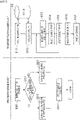
- traveling control unit 11 Upon obtaining the destination inputted by the driver (S101), traveling control unit 11 refers to the 3D map data stored in map DB 110 to perform route calculation for generation of route data (S102).
- the route data is data representing target route 1R for letting the subject point of vehicle 5 pass at the time of automatic driving control.
- the route data is a series of data of center locations (absolute positions) of lane 300.
- magnetic markers 30 are arrayed along the center of lane 300. Therefore, target route 1R represented by the route data matches a laying line of magnetic markers 30.
- vehicle 5 In automatic driving control, vehicle 5 is controlled so that the subject point of vehicle 5 passes through target route 1R (predetermined route). Note that the subject point of vehicle 5 is updated as occasion arises during automatic driving control.
- the own vehicle position in the following description means an absolute position of the subject point being set.
- positioning unit 12 controls sensor unit 2 to cause the above-described marker detection process to be repeatedly performed (S201). If magnetic marker 30 has been detected (S202: YES), positioning unit 12 obtains the lateral shift amount of the subject point with respect to that magnetic marker 30 and also obtains marker position information (position data) of RFID tag 35 (S223).
- Positioning unit 12 identifies, as the own vehicle position (exemplarily indicated by a ⁇ mark in FIG. 8 ), a position offset by the lateral shift amount with reference to the laying position of magnetic marker 30 indicated by the position data (S204).
- the above-described lateral shift amount is the lateral shift amount of the subject point of vehicle 5 with respect to magnetic marker 30.
- the own vehicle position is the absolute position of the subject point of vehicle 5.
- positioning unit 12 estimates a relative position of vehicle 5 with respect to the latest own vehicle position identified at the time of detection of magnetic marker 30 (position indicated by the ⁇ mark in FIG. 8 ). Specifically, positioning unit 12 estimates the above-described relative position by integration of displacement amounts similarly taken in along the azimuths of vehicle 5 taken in from IMU 22.
- positioning unit 12 identifies the position of a x mark obtained by shifting the position by this relative position to the latest own vehicle position (position indicated by the ⁇ mark in FIG. 8 ), identified at the time of detection of magnetic marker 30, as the own vehicle position.
- an arrow in the drawing is one example of a vector representing this relative position.
- the own vehicle position with the ⁇ mark in the drawing is the absolute position of the subject point of vehicle 5.
- the own vehicle position with the ⁇ mark obtained by shifting by the relative position to the own vehicle position with the ⁇ mark in the drawing is also the absolute position of the subject point of vehicle 5.
- Positioning unit 12 inputs the identified own vehicle position (the position with the ⁇ mark or the ⁇ mark in FIG. 8 ) to traveling control unit 11.
- traveling control unit 11 Upon obtaining the own vehicle position, traveling control unit 11 identifies the own vehicle position in target route 1R. Then, traveling control unit 11 identifies the shape of the route ahead of vehicle 5 (S103) . Traveling control unit 11 identifies, for example, a curvature of a curve ahead or the like as a route specification, which is a shape specification of the route of vehicle 5 ahead.
- the shape of the route ahead means a route shape several meters ahead of vehicle 5.
- the route shape may be a route shape at a location several tens of meters ahead or at a location vehicle 5 has reached (zero meter ahead). For example, if the route shape has been identified before a location, its route shape may be identified when it is estimated to have reached at that location.
- traveling control unit 11 selects a new subject point (S104, subject-point selection process).
- subject-point selection process for example, a position having reflected thereon a route specification such as the curvature of a curve, and a vehicle specification such as the vehicle width or wheel base is selected as a new subject point.
- a new subject point may be selected in consideration of only either one of the route specification and the vehicle specification. Note that details of the subject-point selection process will be described further below.
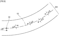
- Traveling control unit 11 updates the subject point as a control subject with the subject point newly selected at step S104 (S105, subject-point updating process). Then, for the newly updated subject point, as in FIG. 9 , traveling control unit 11 calculates deviation ⁇ D from target route 1R (S106). Then, traveling control unit 11 performs vehicle control such as steering control and throttle control so that this deviation ⁇ D becomes closer to zero, thereby achieving automatic driving (S107).
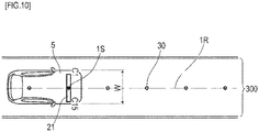
- target route 1R represented by the route data of the present embodiment indicates a position at the center of lane 300 forming a traveling route, that is, a position on the laying line of magnetic markers 30.
- vehicle 5 is controlled so as to travel along the center of lane 300.
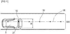
- the position of leftward magnetic sensor C3 is set as subject point 1S, as in FIG. 11 , the vehicle is controlled so as to travel rightward in lane 300.
- the subject-point selection process at step S104 in FIG. 7 is a process for selecting the subject point of vehicle 5.
- any position on the straight line where fifteen magnetic sensors C1 to C15 (Cn) are arrayed is selected as the subject point.
- the subject point may be an intermediate position between adjacent magnetic sensors, for example, C9.5 or the like.
- the position of the subject point is represented as the position of magnetic sensor C8, the position of magnetic sensor C2, or the like.
- correction coefficients ( FIG. 12 , FIG. 13 ) to be applied to the subject-point selection process are defined.
- Correction coefficient D1 of FIG. 12 is a correction coefficient in accordance with the curvature of a curve (one example of a route specification) .
- Correction coefficient D2 of FIG. 13 is a correction coefficient in accordance with the wheel base (one example of a vehicle specification). Note that as in FIG. 12 and FIG. 13 , the values of correction coefficients D1 and D2 increase as vehicle width W is larger. This is because the necessity to correct the subject point increases as vehicle width W is larger.
- a new subject point is selected by solving the following Equation 1.
- new subject point initially ⁇ set subject point ⁇ D1 ⁇ D2
- the initially-set subject point in Equation 1 is a subject point suitable for, for example, a straight road.
- the position of magnetic sensor C8 corresponding to the center of vehicle 5 is set.
- the value (initially-set subject point) in Equation 1 is 8.
- the position of magnetic sensor C3 is selected as a new subject point.
- Equation 1 " ⁇ " for switching whether the correction amount (D1 ⁇ D2) is added to or subtracted from the initially-set subject point is defined depending on a left curve or right curve.
- a left curve in consideration of the inner wheel difference, vehicle 5 is required to be pulled to the right in the lane.
- the correction amount is preferably subtracted from the initially-set subject point so as to allow a leftward subject point to be selected.
- the above-described Equation 1 is (initially-set subject point)-(D1 ⁇ D2).
- vehicle 5 is required to be pulled to the left in the lane.
- the correction amount is preferably added to the initially-set subject point so as to allow a rightward subject point to be selected.
- the above-described Equation 1 is (initially-set subject point)+(D1 ⁇ D2).
- an appropriate subject point can be calculated in accordance with whether the route ahead (several meters ahead) is straight or curved. For example, when the route ahead is in a straight line, the curvature is approximately zero, and correction coefficient D1 is thus approximately zero. Therefore, when the route ahead is in a straight line, irrespective of the value of correction coefficient D2, the correction amount is approximately zero, and a subject point positioned close to the initially-set subject point is selected. On the other hand, when the route ahead is curved, correction coefficient D1 has a large value, and the correction amount becomes a large amount. With this, a subject point positioned away from the initially-set subject point is selected.
- the subject-point selection process with Equation 1 described above is a process in which correction of the subject point is not performed when the route ahead is in a straight line and the degree of correction of the subject point is intensified when the curvature of the curve ahead is large.
- the degree of correction varies also depending on vehicle width W. As vehicle width W is larger, correction coefficients D1 and D2 increase (refer to FIG. 12 and FIG. 13 ) and thus the degree of correction is intensified.
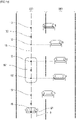
- FIG. 14 depicts an inner wheel difference occurring at the time of passing through a tight left curve, with the subject point being still set at the position of magnetic sensor C8.
- the left rear wheel is pulled inward too much due to the inner wheel difference, and inner space S of the curve becomes insufficient.
- FIG. 15 when the position of leftward magnetic sensor C2 is set as the subject point, vehicle 5 can travel with a large rightward turn in the lane of the left curve. In this case, the left rear wheel is not pulled inward too much, and inner space S of the curve can be sufficiently ensured.
- center magnetic sensor C8 is selected as a subject point in the straight-line zone, the position of vehicle 5 does not lean in the lane. If a leftward subject point, for example, magnetic sensor C2, is selected in the curve zone, the left rear wheel on the inner side of the curve is not pulled inward too much.
- Path RG of the left rear wheel of vehicle 5 is, as in FIG. 16 , a favorable path with a portion corresponding to the straight-line zone of path R8 of the left rear wheel when the subject point is at the position of magnetic sensor C8 and a portion corresponding to the curve zone of path R2 of the left rear wheel when the subject point is at the position of magnetic sensor C2 in combination.
- correction coefficient D2 ( FIG. 13 ) is larger.
- the degree of correction of the subject point can be intensified for a large-sized vehicle having a long wheel base more than a small-sized vehicle.
- automatic driving system 1 of the present embodiment is a system which lets vehicle 5 travel by automatic steering so that the subject point of vehicle 5 passes through target route 1R.
- Automatic driving system 1 has one of technical features in selecting a subject point as a control subject and updating it as occasion arises.
- automatic driving system 1 by updating the subject point as a control subject, the route where vehicle 5 actually travels can be adjusted.
- this automatic driving system 1 in adjusting the actual traveling route of vehicle 5, it is less necessary to change the control specifications and the target route.
- Automatic driving system 1 can adjust the actual traveling route of vehicle 5 without changing the control specifications and the target route, and can be applied with high versatility to various vehicle types and traveling roads.
- the curvature of the curve is exemplarily described as a route specification in the present embodiment.
- the lane width and the type of the lane may be included in route specifications. This is because it is more required to control the position of the vehicle on the lane with high accuracy as the lane width is narrower.
- As the type of the lane there are types such as an expressway or ordinary road; an outer lane or inner lane of two lanes on one side, and so forth.
- setting screen 50 ( FIG. 17 ) which allows the driver to set a preference in the vehicle position in the lane may be displayed on a vehicle onboard monitor.
- the vehicle position can be adjusted by using right-oriented triangular mark 50R and left-oriented triangular mark 50L, and a preferred vehicle position can be set in accordance with operation on decision button 52.
- the position of the subject point is preferably corrected in accordance with the preferred position of a touch vehicle set by using setting screen 50.
- the vehicle onboard monitor in this configuration forms one example of an operating part to be operated by the driver to adjust the position in the traveling road occupied by the vehicle in the vehicle-width direction.
- Traveling control unit 11 as a subject-point selection processing part preferably adjusts the subject point leftward (rightward) when, for example, a leftward (rightward) position is selected by driver's operation on the operating part.
- this adjustment it is possible to adopt, for example, shifting the subject point selected by the above-described subject-point selection process by a predetermined amount, adjustment of shifting the initially-set subject point in Equation 1 described above by a predetermined amount, and so forth.
- a driver-preferred position of the vehicle may be learnt from the position of the vehicle during manual driving or the like. Furthermore, a driver-preferred position of the vehicle may be learnt by differentiation for each road type. In this case, the traveling control unit can finely select a subject point by using the results of learning the driver's preference for each road type. If a subject point is selected in accordance with the drive in this manner, the traveling route of vehicle 5 by automatic driving can be made closer to the traveling route when the driver drives, thereby reducing a sense of incongruity the driver can feel during automatic driving.
- a subject point may be two-dimensionally selected in a horizontal plane parallel to the road surface.
- a subject point may be selected irrespective of the inside or outside of the vehicle.
- FIG. 18 when another vehicle 59 is parked overhanging into the traveling road forming target route 1R, subject point 1S can be selected outside vehicle 5.
- a subject point is selected outside vehicle 5 by the subject-point selection process, it is possible to make a lane change for overtaking and passing a preceding vehicle traveling on the lane of target route 1R, and so forth.
- subject point 1S as a control subject, it is possible to perform control for avoiding an obstacle on target route 1R, control for making a lane change, and so forth.
- subject point 1S positioned outside vehicle 5 it is possible to perform lateral control with a displacement amount in a lateral direction as exceeding the vehicle width or a half of the vehicle width.
- subject point 1S as a control subject can be positioned as overlapping preceding vehicle 591 or positioned on another lane 300 adjacent to lane 300 where vehicle 5 is positioned.
- correction coefficient D3 may be adopted, the value of which increases in accordance with the steering angle of the wheel to be steered.
Landscapes
- Engineering & Computer Science (AREA)
- Mechanical Engineering (AREA)
- Transportation (AREA)
- Automation & Control Theory (AREA)
- Remote Sensing (AREA)
- Radar, Positioning & Navigation (AREA)
- Physics & Mathematics (AREA)
- Chemical & Material Sciences (AREA)
- Combustion & Propulsion (AREA)
- General Physics & Mathematics (AREA)
- Human Computer Interaction (AREA)
- Electromagnetism (AREA)
- Aviation & Aerospace Engineering (AREA)
- Steering Control In Accordance With Driving Conditions (AREA)
- Control Of Position, Course, Altitude, Or Attitude Of Moving Bodies (AREA)
- Control Of Driving Devices And Active Controlling Of Vehicle (AREA)
Applications Claiming Priority (2)
| Application Number | Priority Date | Filing Date | Title |
|---|---|---|---|
| JP2019115911 | 2019-06-21 | ||
| PCT/JP2020/024003 WO2020256070A1 (fr) | 2019-06-21 | 2020-06-18 | Procédé de commande et système de commande pour véhicule |
Publications (2)
| Publication Number | Publication Date |
|---|---|
| EP3989199A1 true EP3989199A1 (fr) | 2022-04-27 |
| EP3989199A4 EP3989199A4 (fr) | 2023-07-19 |
Family
ID=74040852
Family Applications (1)
| Application Number | Title | Priority Date | Filing Date |
|---|---|---|---|
| EP20826872.2A Pending EP3989199A4 (fr) | 2019-06-21 | 2020-06-18 | Procédé de commande et système de commande pour véhicule |
Country Status (5)
| Country | Link |
|---|---|
| US (1) | US20220340202A1 (fr) |
| EP (1) | EP3989199A4 (fr) |
| JP (1) | JP7406130B2 (fr) |
| CN (1) | CN113993762A (fr) |
| WO (1) | WO2020256070A1 (fr) |
Families Citing this family (1)
| Publication number | Priority date | Publication date | Assignee | Title |
|---|---|---|---|---|
| JP7537170B2 (ja) | 2020-08-07 | 2024-08-21 | 株式会社ジェイテクト | 走行支援装置及び磁気マーカの敷設方法 |
Family Cites Families (17)
| Publication number | Priority date | Publication date | Assignee | Title |
|---|---|---|---|---|
| JPH09282033A (ja) * | 1996-04-12 | 1997-10-31 | Toyota Motor Corp | 車両の自動操舵制御装置 |
| JP2001001922A (ja) * | 1999-06-18 | 2001-01-09 | Mazda Motor Corp | 車両の操舵装置 |
| JP2001264076A (ja) | 2000-03-21 | 2001-09-26 | Clarion Co Ltd | カーナビゲーション装置 |
| JP3945185B2 (ja) * | 2001-05-22 | 2007-07-18 | いすゞ自動車株式会社 | 自動操舵装置 |
| JP2005202478A (ja) * | 2004-01-13 | 2005-07-28 | Denso Corp | 車両用自動走行システム |
| JP2007233604A (ja) * | 2006-02-28 | 2007-09-13 | Toyota Motor Corp | 道路情報取得装置、及びこれを利用した車両用走行制御装置、並びに道路交通システム |
| US8392064B2 (en) * | 2008-05-27 | 2013-03-05 | The Board Of Trustees Of The Leland Stanford Junior University | Systems, methods and devices for adaptive steering control of automotive vehicles |
| JP4901919B2 (ja) * | 2009-07-13 | 2012-03-21 | 株式会社東芝 | X線コンピュータ断層撮影装置及びx線検出装置製造方法 |
| DE102013212708B4 (de) * | 2013-06-28 | 2022-01-13 | Volkswagen Aktiengesellschaft | Verfahren und Vorrichtung zur Durchführung autonomer Fahrmanöver eines Fahrzeugs |
| US20150294566A1 (en) * | 2014-04-15 | 2015-10-15 | Tomorrow's Transportation Today | Trip planning and management methods for an intelligent transit system with electronic guided buses |
| JP6559453B2 (ja) * | 2015-03-31 | 2019-08-14 | アイシン・エィ・ダブリュ株式会社 | 自動運転支援システム、自動運転支援方法及びコンピュータプログラム |
| JP6451565B2 (ja) * | 2015-09-09 | 2019-01-16 | 株式会社デンソー | 運転支援装置、及び運転支援方法 |
| US20210192956A1 (en) * | 2016-03-15 | 2021-06-24 | Honda Motor Co., Ltd. | Vehicle control system, vehicle control method, and vehicle control program |
| JP6544878B2 (ja) * | 2016-05-16 | 2019-07-17 | 本田技研工業株式会社 | 車両制御システム、車両制御方法、および車両制御プログラム |
| EP3525192B1 (fr) * | 2016-10-07 | 2022-04-20 | Nissan Motor Co., Ltd. | Procédé d'évaluation de véhicule, procédé de correction d'itinéraire de déplacement, dispositif d'évaluation de véhicule et dispositif de correction d'itinéraire de déplacement |
| JP6923306B2 (ja) * | 2016-11-09 | 2021-08-18 | 株式会社野村総合研究所 | 車両運転支援システム |
| SE540698C2 (en) * | 2017-02-07 | 2018-10-16 | Scania Cv Ab | Method and control unit for estimating bias of yaw rate sensor |
-
2020
- 2020-06-18 WO PCT/JP2020/024003 patent/WO2020256070A1/fr active Application Filing
- 2020-06-18 EP EP20826872.2A patent/EP3989199A4/fr active Pending
- 2020-06-18 US US17/619,592 patent/US20220340202A1/en active Pending
- 2020-06-18 JP JP2021526882A patent/JP7406130B2/ja active Active
- 2020-06-18 CN CN202080043672.4A patent/CN113993762A/zh active Pending
Also Published As
| Publication number | Publication date |
|---|---|
| WO2020256070A1 (fr) | 2020-12-24 |
| EP3989199A4 (fr) | 2023-07-19 |
| US20220340202A1 (en) | 2022-10-27 |
| JPWO2020256070A1 (fr) | 2020-12-24 |
| JP7406130B2 (ja) | 2023-12-27 |
| CN113993762A (zh) | 2022-01-28 |
Similar Documents
| Publication | Publication Date | Title |
|---|---|---|
| EP3605487A1 (fr) | Système de marqueur | |
| WO2020138471A1 (fr) | Procédé de commande de déplacement pour véhicule et système de commande de véhicule | |
| EP3508822B1 (fr) | Système et procédé d'apprentissage pour véhicule | |
| EP3637384B1 (fr) | Système de marqueur et procédé d'utilisation | |
| US11157017B2 (en) | Vehicular system and course estimation method | |
| US11334087B2 (en) | Magnetic marker installation method and work system | |
| US6345217B1 (en) | Automated guided vehicle (AGV) with bipolar magnet sensing | |
| WO2017209112A1 (fr) | Procédé et système de capture de position | |
| CN112204352B (zh) | 陀螺仪传感器的校正方法 | |
| CN110741285B (zh) | 标识器检测方法及车辆用系统 | |
| EP1046568B1 (fr) | Dispositif de détection pour détecter les mouvements d'un véhicule utilisant des marquages de routes | |
| JP2018169301A (ja) | マーカシステム | |
| EP3683547A1 (fr) | Système de capture de position et procédé de capture de position | |
| EP3989199A1 (fr) | Procédé de commande et système de commande pour véhicule | |
| JP7381939B2 (ja) | 3次元構造推定方法及び3次元構造推定システム | |
| EP4411502A1 (fr) | Procédé de commande et système de commande | |
| EP4411503A1 (fr) | Procédé de commande et système de commande |
Legal Events
| Date | Code | Title | Description |
|---|---|---|---|
| STAA | Information on the status of an ep patent application or granted ep patent |
Free format text: STATUS: THE INTERNATIONAL PUBLICATION HAS BEEN MADE |
|
| PUAI | Public reference made under article 153(3) epc to a published international application that has entered the european phase |
Free format text: ORIGINAL CODE: 0009012 |
|
| STAA | Information on the status of an ep patent application or granted ep patent |
Free format text: STATUS: REQUEST FOR EXAMINATION WAS MADE |
|
| 17P | Request for examination filed |
Effective date: 20211215 |
|
| AK | Designated contracting states |
Kind code of ref document: A1 Designated state(s): AL AT BE BG CH CY CZ DE DK EE ES FI FR GB GR HR HU IE IS IT LI LT LU LV MC MK MT NL NO PL PT RO RS SE SI SK SM TR |
|
| DAV | Request for validation of the european patent (deleted) | ||
| DAX | Request for extension of the european patent (deleted) | ||
| A4 | Supplementary search report drawn up and despatched |
Effective date: 20230615 |
|
| RIC1 | Information provided on ipc code assigned before grant |
Ipc: G08G 1/127 20060101ALI20230609BHEP Ipc: B62D 15/02 20060101ALI20230609BHEP Ipc: G01V 3/08 20060101ALI20230609BHEP Ipc: B60W 30/12 20200101ALI20230609BHEP Ipc: G08G 1/00 20060101AFI20230609BHEP |
|
| STAA | Information on the status of an ep patent application or granted ep patent |
Free format text: STATUS: EXAMINATION IS IN PROGRESS |
|
| 17Q | First examination report despatched |
Effective date: 20240130 |