EP3988397A1 - Unité de commande électrique - Google Patents
Unité de commande électrique Download PDFInfo
- Publication number
- EP3988397A1 EP3988397A1 EP20382922.1A EP20382922A EP3988397A1 EP 3988397 A1 EP3988397 A1 EP 3988397A1 EP 20382922 A EP20382922 A EP 20382922A EP 3988397 A1 EP3988397 A1 EP 3988397A1
- Authority
- EP
- European Patent Office
- Prior art keywords
- main
- ecu
- illumination system
- signals
- auxiliary
- Prior art date
- Legal status (The legal status is an assumption and is not a legal conclusion. Google has not performed a legal analysis and makes no representation as to the accuracy of the status listed.)
- Granted
Links
- 238000005286 illumination Methods 0.000 claims abstract description 110
- 238000000034 method Methods 0.000 claims abstract description 64
- 238000004590 computer program Methods 0.000 claims abstract description 17
- 238000004891 communication Methods 0.000 claims description 19
- 230000006870 function Effects 0.000 claims description 18
- 238000012935 Averaging Methods 0.000 claims description 4
- 230000001276 controlling effect Effects 0.000 description 34
- 230000008878 coupling Effects 0.000 description 7
- 238000010168 coupling process Methods 0.000 description 7
- 238000005859 coupling reaction Methods 0.000 description 7
- 238000010586 diagram Methods 0.000 description 4
- 230000003287 optical effect Effects 0.000 description 3
- 230000001105 regulatory effect Effects 0.000 description 3
- 238000013459 approach Methods 0.000 description 2
- 230000008569 process Effects 0.000 description 2
- 230000007704 transition Effects 0.000 description 2
- 241001236644 Lavinia Species 0.000 description 1
- 230000005540 biological transmission Effects 0.000 description 1
- 238000004364 calculation method Methods 0.000 description 1
- 230000001143 conditioned effect Effects 0.000 description 1
- 230000003750 conditioning effect Effects 0.000 description 1
- 238000001514 detection method Methods 0.000 description 1
- 238000011161 development Methods 0.000 description 1
- 238000009429 electrical wiring Methods 0.000 description 1
- 238000010348 incorporation Methods 0.000 description 1
- 230000000977 initiatory effect Effects 0.000 description 1
- 230000003993 interaction Effects 0.000 description 1
- 238000012986 modification Methods 0.000 description 1
- 230000004048 modification Effects 0.000 description 1
- 239000004065 semiconductor Substances 0.000 description 1
- 238000012546 transfer Methods 0.000 description 1
- 238000012795 verification Methods 0.000 description 1
Images

Classifications
-
- B—PERFORMING OPERATIONS; TRANSPORTING
- B60—VEHICLES IN GENERAL
- B60R—VEHICLES, VEHICLE FITTINGS, OR VEHICLE PARTS, NOT OTHERWISE PROVIDED FOR
- B60R16/00—Electric or fluid circuits specially adapted for vehicles and not otherwise provided for; Arrangement of elements of electric or fluid circuits specially adapted for vehicles and not otherwise provided for
- B60R16/02—Electric or fluid circuits specially adapted for vehicles and not otherwise provided for; Arrangement of elements of electric or fluid circuits specially adapted for vehicles and not otherwise provided for electric constitutive elements
- B60R16/023—Electric or fluid circuits specially adapted for vehicles and not otherwise provided for; Arrangement of elements of electric or fluid circuits specially adapted for vehicles and not otherwise provided for electric constitutive elements for transmission of signals between vehicle parts or subsystems
-
- B—PERFORMING OPERATIONS; TRANSPORTING
- B60—VEHICLES IN GENERAL
- B60D—VEHICLE CONNECTIONS
- B60D1/00—Traction couplings; Hitches; Draw-gear; Towing devices
- B60D1/58—Auxiliary devices
- B60D1/62—Auxiliary devices involving supply lines, electric circuits, or the like
-
- B—PERFORMING OPERATIONS; TRANSPORTING
- B60—VEHICLES IN GENERAL
- B60D—VEHICLE CONNECTIONS
- B60D1/00—Traction couplings; Hitches; Draw-gear; Towing devices
- B60D1/58—Auxiliary devices
- B60D1/62—Auxiliary devices involving supply lines, electric circuits, or the like
- B60D1/64—Couplings or joints therefor
-
- B—PERFORMING OPERATIONS; TRANSPORTING
- B60—VEHICLES IN GENERAL
- B60R—VEHICLES, VEHICLE FITTINGS, OR VEHICLE PARTS, NOT OTHERWISE PROVIDED FOR
- B60R16/00—Electric or fluid circuits specially adapted for vehicles and not otherwise provided for; Arrangement of elements of electric or fluid circuits specially adapted for vehicles and not otherwise provided for
- B60R16/02—Electric or fluid circuits specially adapted for vehicles and not otherwise provided for; Arrangement of elements of electric or fluid circuits specially adapted for vehicles and not otherwise provided for electric constitutive elements
- B60R16/023—Electric or fluid circuits specially adapted for vehicles and not otherwise provided for; Arrangement of elements of electric or fluid circuits specially adapted for vehicles and not otherwise provided for electric constitutive elements for transmission of signals between vehicle parts or subsystems
- B60R16/0239—Electronic boxes
-
- B—PERFORMING OPERATIONS; TRANSPORTING
- B60—VEHICLES IN GENERAL
- B60R—VEHICLES, VEHICLE FITTINGS, OR VEHICLE PARTS, NOT OTHERWISE PROVIDED FOR
- B60R16/00—Electric or fluid circuits specially adapted for vehicles and not otherwise provided for; Arrangement of elements of electric or fluid circuits specially adapted for vehicles and not otherwise provided for
- B60R16/02—Electric or fluid circuits specially adapted for vehicles and not otherwise provided for; Arrangement of elements of electric or fluid circuits specially adapted for vehicles and not otherwise provided for electric constitutive elements
- B60R16/03—Electric or fluid circuits specially adapted for vehicles and not otherwise provided for; Arrangement of elements of electric or fluid circuits specially adapted for vehicles and not otherwise provided for electric constitutive elements for supply of electrical power to vehicle subsystems or for
- B60R16/0315—Electric or fluid circuits specially adapted for vehicles and not otherwise provided for; Arrangement of elements of electric or fluid circuits specially adapted for vehicles and not otherwise provided for electric constitutive elements for supply of electrical power to vehicle subsystems or for using multiplexing techniques
-
- H—ELECTRICITY
- H05—ELECTRIC TECHNIQUES NOT OTHERWISE PROVIDED FOR
- H05B—ELECTRIC HEATING; ELECTRIC LIGHT SOURCES NOT OTHERWISE PROVIDED FOR; CIRCUIT ARRANGEMENTS FOR ELECTRIC LIGHT SOURCES, IN GENERAL
- H05B47/00—Circuit arrangements for operating light sources in general, i.e. where the type of light source is not relevant
- H05B47/10—Controlling the light source
- H05B47/175—Controlling the light source by remote control
- H05B47/18—Controlling the light source by remote control via data-bus transmission
-
- B—PERFORMING OPERATIONS; TRANSPORTING
- B60—VEHICLES IN GENERAL
- B60Q—ARRANGEMENT OF SIGNALLING OR LIGHTING DEVICES, THE MOUNTING OR SUPPORTING THEREOF OR CIRCUITS THEREFOR, FOR VEHICLES IN GENERAL
- B60Q1/00—Arrangement of optical signalling or lighting devices, the mounting or supporting thereof or circuits therefor
- B60Q1/26—Arrangement of optical signalling or lighting devices, the mounting or supporting thereof or circuits therefor the devices being primarily intended to indicate the vehicle, or parts thereof, or to give signals, to other traffic
- B60Q1/30—Arrangement of optical signalling or lighting devices, the mounting or supporting thereof or circuits therefor the devices being primarily intended to indicate the vehicle, or parts thereof, or to give signals, to other traffic for indicating rear of vehicle, e.g. by means of reflecting surfaces
- B60Q1/305—Indicating devices for towed vehicles
Definitions
- This disclosure relates to an electronic control unit, ECU, for controlling an auxiliary illumination system depending on a main illumination system of a vehicle, and to a replaceable card connectable with such an ECU.
- the present disclosure further relates to a method of controlling an auxiliary illumination system depending on a main illumination system of a vehicle through said ECU and replaceable card, and to a computer program suitable for performing such a method.
- towing systems that act as an interface or coupling between a vehicle with a main illumination system and an auxiliary structure with an auxiliary illumination system which is towable by the vehicle through the towing system.
- towable auxiliary structures are house trailers, mobile homes, truck trailers, wagons, containers, caravans, etc.
- towing hitches are installed in automobiles, it has been necessary to transfer lighting functions from the main illumination system (of the vehicle) to the auxiliary illumination system (of the towing or towable auxiliary structure). This requires unfolding these functions and send the voltage to the pilot lights of both the vehicle and the towing.
- Different types of electrical wiring exist for that purpose, such as, e.g., Universal and Specific configurations.
- the cables for towing service are connected directly with those of the vehicle by means of quick connectors, e.g., one for each lighting function.
- the wiring for towing service is connected to those of the vehicle through specific connectors for each vehicle model or directly to Can-Bus lines of the vehicle.
- Can Bus Data may be defined as a protocol for transmission of digital information between different devices in the vehicle, wherein a Main Control Unit manages any element of the vehicle, both for security and comfort or engine management. Information flows through, e.g., a pair of twisted cables linking all the communication nodes forming the electronic system (including the main illumination system) of the vehicle. It is thus possible to increase the functions in vehicles by reducing the number of cables that are necessary for their operation.
- An object of the present disclosure is to provide new systems, methods and computer programs aimed at improving current manners of controlling an auxiliary illumination system depending on a main illumination system of a vehicle.
- an electronic control unit for controlling an auxiliary illumination system depending on a main illumination system of a vehicle.
- the ECU comprises a connector module configured to implement a connection between the ECU and a replaceable card configured to receive one or more main digital signals from the main illumination system through a CAN bus.
- the ECU further comprises a processor module configured to read the received one or more main digital signals, and to generate one or more first auxiliary signals depending on said one or more main digital signals to control the auxiliary illumination system at least partially based on the generated one or more first auxiliary signals.
- Such a proposed ECU conforms a very versatile mean/way of controlling auxiliary lighting system depending on main lighting system of a vehicle, since the ECU may be the same for all types of vehicle configurations. That is, the same ECU configuration may be used with any type of vehicle configuration by simply connecting proper replaceable card with the ECU. One replaceable card or another may be used whenever the selected card satisfies corresponding specificities of the particular vehicle where the kit of ECU and card is to be used.
- the ECU may further comprise an analog module configured to receive one or more main analog signals from the main illumination system, and the processor module may be configured to read the received one or more main analog signals, and to generate one or more second auxiliary signals depending on said one or more main analog signals to control the auxiliary illumination system further based on the generated one or more second auxiliary signals.
- the processor module may be configured to read the received one or more main analog signals, and to generate one or more second auxiliary signals depending on said one or more main analog signals to control the auxiliary illumination system further based on the generated one or more second auxiliary signals.
- full analog mode may be performed through the analog module or, otherwise (card is connected), the ECU may operate in full digital mode or in combined digital-analog mode. Versatility of the ECU is thus improved with this feature.
- the processor module may be configured to read the received one or more main analog signals as ON-OFF signals and/or based on pulse-width modulation, PWM.
- the processor module may be configured to read (all or part of) the one or more main analog signals based on PWM by calculating (corresponding) PWM values and determining, for each of said PWM values, whether the PWM value corresponds to one or other main analog signal depending on whether the PWM value is above or below a PWM threshold.
- the processor module may be configured to calculate the PWM threshold for distinguishing between two of the main analog signals by calculating first dominant PWM value for a first of the two main analog signals and second dominant PWM value for a second of the two main analog signals, and averaging said first and second dominant PWM values.
- PWM-based manners of reading main analog signals may be very valuable when a single connection/cable/wire is used to transmit main analog signals.
- one of the main digital signals and one of the main analog signals may correspond to same light function in the vehicle, and the processor module may be configured to verify whether said one of the main digital signals and said one of the main analog signals substantially correspond to same value for said same light function in the vehicle. Reliability of the ECU is improved with such a feature, which may be seen as a digital-analog checker of main signals (from main lighting system). If main signals of same light function digitally and analogically processed result in divergent/discrepant (too different) values, it may be determined that something is malfunctioning or, otherwise, good reliability may be confirmed.
- the processor module may be further configured to read from a memory in the replaceable card data denoting a model of the vehicle and/or a standard to which the CAN bus corresponds.
- the processor module may be configured to read the received one or more main digital signals depending on the model of the vehicle and/or the CAN bus standard, and/or to generate the one or more first auxiliary signals further depending on the model of the vehicle and/or the CAN bus standard.
- the processor module may comprise a communication module configured to implement a wireless communication between the processor module and another device or devices. This communication may be very useful to, e.g., configure or customize the processor module from, e.g., smartphone, tablet, laptop or any portable (or even non-portable) computing device.
- the processor module may be further configured to write data from the auxiliary illumination system to be sent to the main illumination system by (or through) the replaceable card via CAN bus. Said feature further improves versatility of the ECU, since operational data may be sent from auxiliary to main lighting system, such as e.g. feedback to main digital and/or analog signals, status of some component(s) of the auxiliary illumination system, instructions to be executed by the main illumination system, etc.
- a replaceable card which is connectable with an electronic control unit (ECU) such as the ones described in other parts of the disclosure, the replaceable card being configured to receive one or more main digital signals through a CAN bus from a main illumination system of a vehicle.
- ECU electronice control unit
- the replaceable card may comprise a memory, such as, e.g., an electrically erasable programmable read-only memory (EEPROM) storing or being configured to store data denoting a model of the vehicle and/or a standard to which the CAN bus corresponds.
- EEPROM electrically erasable programmable read-only memory
- This memory may include, for example, a wireless module configured to implement a wireless communication between the memory and another device or devices.
- This wireless module may be, for example, a Near Field Communication (NFC) module.
- NFC Near Field Communication
- an ECU kit including an ECU such as the ones described in other parts of the disclosure and a replaceable card such as the ones described in other parts of the disclosure, the ECU and the replaceable card being connectable with each other.
- the replaceable card may be, for example, insertable in a groove or female coupling part of the ECU.
- a method for controlling an auxiliary illumination system depending on a main illumination system of a vehicle through an electronic control unit (ECU).
- the method comprises receiving, by a replaceable card connected with the ECU, one or more main digital signals from the main illumination system through a CAN bus, and reading, by a processor module in the ECU, the received one or more main digital signals.
- the method further comprises generating, by the processor module, one or more first auxiliary signals depending on the one or more main digital signals to control the auxiliary illumination system at least partially based on the generated one or more first auxiliary signals.
- a computer program comprising program instructions for causing a computing system to perform such a method of controlling an auxiliary illumination system.
- the computer program may be embodied on a storage medium and/or carried on a carrier signal.
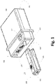
- FIG. 1 schematically illustrates an external view of an ECU 108 and a replaceable card 109 connectable therewith for controlling an auxiliary illumination system depending on a main illumination system of a vehicle, according to examples.
- ECUs 108 may include a protecting case or cover 100 configured to protect the interior of the ECU, e.g., whole electronics in the ECU 108.
- ECUs 108 may further comprise a groove or female coupling part 103 into which replaceable card 109 is insertable.
- ECUs 108 may still further include analog port/line or ports/lines 104 for analog connections with main illumination system of the vehicle.
- ECUs 108 may yet further comprise an opening 102 for a user to interact with replaceable card 109 when inserted into or coupled with the ECU 108. Opening 102 may permit the user to access a push element 105 of the replaceable card 109 through, e.g., a finger. Opening 102 may be configured to fit the push element 105 in a way that the replaceable card 109 is stably fixed within female coupling part 103. This stable fixation may ensure that inner connectors (not shown) of the ECU 108 and connectors 107 of the replaceable card 109 electrically contact to each other.
- ECUs 108 may additionally comprise connection port/line or ports/lines 110 for electrical coupling of the ECU 108 with/to auxiliary illumination system.
- Replaceable cards 109 may include a CAN bus connection port/line 106 for connecting the replaceable card 109 with CAN bus of the vehicle, so that main digital signal(s) are receivable by the replaceable card 109 through said connection port/line 106.
- replaceable cards 109 may comprise a push element 105 which, once the replaceable card 109 is completely inserted within female part 103, the push element 105 may fit within opening 102.
- Such a fitting may be based on, e.g., a click-based fitting or coupling.
- Replaceable cards 109 may still further include, for example, a guiding element 101 configured to facilitate introduction/coupling of the replaceable card 109 into groove or female part 103 of the ECU 108.
- This guiding element 101 which may be, e.g., at a lateral side of the replaceable card 109, may also ensure stable fixation of replaceable card 109 within ECU 108.
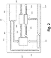
- FIG. 2 is a block diagram schematically illustrating electronics of an ECU 200 according to examples, with the aim of controlling an auxiliary illumination system depending on a main illumination system of a vehicle.
- ECUs 200 may comprise a connector module 201 and a processor module 210.
- the connector module 201 may be configured to implement a connection between the ECU 200 and a replaceable card configured to receive main digital signal(s) from the main illumination system through CAN bus.
- the processor module 210 such as, e.g., a microcontroller, may be configured to read the main digital signal(s) received by the replaceable card.
- the processor module 210 may be further configured to generate first auxiliary signal(s) depending on said main digital signal(s) to control the auxiliary illumination system at least partially based on the generated first auxiliary signal(s).
- the processor module 210 may be configured to read the main digital signal(s) received by the replaceable card 201 through, e.g., a signal and data bus 207 connecting the processor 210 and the (installed/inserted) card 201 with each other.
- ECUs 200 may further comprise an analog module 202, 206 configured to receive main analog signal(s) from the main illumination system.
- the processor module 210 may be further configured to read the received main analog signal(s) through the analog module 202, 206.
- the processor 210 may be further configured to generate second auxiliary signal(s) depending on said main analog signal(s) to control the auxiliary illumination system further based on the generated second auxiliary signal(s).
- the analog module 202, 206 may comprise, e.g., a vehicle light input port/line 202 configured to receive the main analog signal(s) from the main illumination system of the vehicle.
- the analog module 202, 206 may further comprise, e.g., voltage adapters 206 configured to adapt the received main analog signal(s) so that they result understandable and processable by the processor 210.
- the processor 210 may read the received main analog signal(s) through suitable signal bus 209 connecting voltage adapters 206 and processor 210 with each other.
- the processor module 210 may be configured to output first auxiliary signal(s) derived from main digital signal(s) and/or second auxiliary signal(s) derived from main analog signal(s) through, e.g., a light control bus 205 connecting the processor module 210 and a light power stage module 204 with each other.
- a light power stage 204 may be configured to condition the first and/or second auxiliary signal(s) from the processor module 210, and to output the conditioned first and/or second auxiliary signal(s) through a light power output 203 towards the auxiliary illumination system.
- This conditioning of the first and/or second auxiliary signal(s) may include any known electrical treatment of the first and/or second auxiliary signal(s) so that they result understandable and processable by the auxiliary illumination system.
- the light power stage 204 may include, e.g., a digital-to-analog (D/A) converter configured to transform digital first and/or second auxiliary signal(s) from the processor 210 into analog first and/or second auxiliary signal(s) to be processed by the auxiliary illumination system.
- D/A digital-to-analog
- a main voltage input port/line 214 may be configured to receive power from the vehicle to electrically feed different components of the ECU 200 that need to be powered.
- the main voltage line 214 may be configured to supply power from the vehicle to, e.g., the processor module 210, and/or the light power stage 204, and/or the (installed/inserted) card 201, etc.
- Such a power from the vehicle may be regulated by, e.g., main voltage regulator(s) 213, so that said regulated power may be then supplied to the processor module 210 through suitable connection 211 between the regulator(s) 213 and the processor 210.
- Proper connection 208 between regulator(s) 213 and connector 201 may also exist for the regulator(s) 213 to supply regulated power to the (installed/inserted) card 201.
- the processor module 210 may be configured to read the received main analog signal(s) as ON-OFF signals and/or based on pulse-width modulation (PWM). In the latter case, the processor 210 may be configured to calculate PWM values (from received main analog signals) and determining, for each of the PWM values, whether the PWM value corresponds to one or other main analog signal depending on a difference between the PWM value and a PWM threshold. The processor 210 may be further configured to calculate or estimate the PWM threshold for distinguishing between two main analog signals. Said calculation/estimation may include determining a first dominant PWM value for one of the two main analog signals and a second dominant PWM value for the other of the two main analog signals, and averaging said first and second dominant PWM values.
- PWM pulse-width modulation
- Said average PWM value may be used as the PWM threshold in a way that if a PWM value or values are generally above or below the PWM threshold, said PWM value or values may be determined as corresponding to one or another main analog signal. If more than two main analog signals are to be identified through PWM, first and second PWM thresholds may be estimated and used in a way that PWM value(s) above first PWM threshold correspond to one of the main analog signals, PWM value(s) between first and second PWM thresholds correspond to another of the main analog signals, and PWM value(s) below second PWM threshold correspond to a further of the main analog signals. Same principle/approach may be applied for any number of different main analog signals. This PWM-based manner of reading main analog signals may be very useful when a single connection/cable/wire is used to transmit main analog signals.
- ECUs 200 may be configured to process (in the terms expressed above) only main digital signals (full digital mode), only main analog signals (full analog mode), or main digital and analog signals (combined mode).
- a main digital signal and a main analog signal may correspond to same light function in the vehicle.
- the processor 210 may be configured to verify whether said main digital signal and main analog signal substantially correspond to same value for said same light function in the vehicle.
- This approach may permit detecting failures if, for example, main digital signal and main analog signal that are supposed to be the same light function produce discrepant values for first and second auxiliary signals. Said discrepancy may be determined depending on whether a difference between said values is above or below a difference threshold. If above, the difference may be excessive and, therefore, an error may be occurring. If below, the difference may be acceptable and, therefore, no error is occurring.
- the processor 210 may be configured to read from a memory (e.g., an EEPROM) in the replaceable card data indicating a model of the vehicle and/or a standard to which the CAN bus corresponds.
- the processor 210 may be further configured to read the received main digital signal(s) depending on the model of the vehicle and/or on the CAN bus standard, and/or to generate the first auxiliary signal(s) further depending on the model of the vehicle and/or on the CAN bus standard.
- the processor 210 may be self-configured according to particularities and/or requirements corresponding to the vehicle model and/or CAN bus standard.
- the processor module 210 may further comprise a communication module (e.g., an NFC module) configured to implement a wireless communication between the processor module 210 and another device or devices.
- a communication module e.g., an NFC module
- This communication may be very useful to transmit data from an external device (e.g., a smartphone) to the processor 210 such that it may be self-configured depending on said data from the external device.
- Such data wirelessly transmitted to the processor 210 may define, e.g., particularities and/or requirements corresponding to the vehicle model and/or CAN bus standard.
- the processor module 210 may be further configured to write data from the auxiliary illumination system to be sent to the main illumination system by the replaceable card through CAN bus. This data may be supplied by the processor 210 to the replaceable card 201 through the signal and data bus 207, and subsequently sent by the replaceable card 201 to the auxiliary illumination system. This data may comprise, e.g., feedback to main digital and/or analog signals, status of some component(s) of the auxiliary illumination system, instructions to be executed by the main illumination system, etc.
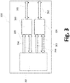
- FIG 3 is a block diagram schematically illustrating electronics of a replaceable card 300 according to examples.
- Replaceable cards 300 may be connectable with ECUs 200 ( Figure 2 ) according to present disclosure and configured to receive main digital signal(s) through CAN bus from a main illumination system of a vehicle.
- ECUs 200 and its interaction with replaceable cards 300 may be equally or similarly applicable to replaceable cards 300 according to Figure 3 .
- Replaceable cards 300 may comprise a memory 304 that may store or may be configured to store data denoting a model of the vehicle and/or a standard to which the CAN bus corresponds.
- This memory 304 may include, e.g., an electrically erasable programmable read-only memory, EEPROM.
- the memory 304 may further include a wireless module (e.g., a Near Field Communication, NFC, module) configured to implement a wireless communication between the memory and another device or devices. This communication may be very useful to configurate the replaceable card 300 from an external device (e.g., a smartphone) with, e.g., particularities and/or requirements corresponding to a model of the vehicle and/or CAN bus standard.
- memory and wireless module are shown within same module 304, but they may be separate modules.
- replaceable cards 300 may be configured to receive power supply from the ECU 200 as explained with reference to, e.g., Figure 2 .
- replaceable cards 300 may include a main card 307 which may be configured to control (or manage) different components forming the replaceable card 300.
- the main card 307 may be configured to, e.g., receive power supply from ECU 200 and, in said case, to forward said power to memory 304 through power connection 306 between main card 307 and memory 304, and/or to a CAN bus transceiver 303 through power connection 309 between main card 307 and CAN bus transceiver 303.
- Main card 307 may be configured to interchange data with memory 304 through data bus 305 implementing data connection between main card 307 and data bus 305, and/or with CAN bus transceiver 303 through data bus 308 implementing data connection between main card 307 and CAN bus transceiver 303.
- Memory-NFC module 304 may be configured to receive and/or interchange data with external device (e.g., smartphone) through corresponding wireless (e.g. NFC) port/line 302.
- CAN bus transceiver 303 may be configured to receive main digital signals from (and/or to generally interchange CAN bus data/signals with) the main illumination system through corresponding CAN bus port/line 301.
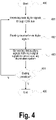
- Figure 4 is a flow chart schematically illustrating methods of controlling an auxiliary illumination system depending on a main illumination system of a vehicle through a kit of ECU and replaceable card, according to examples.
- controlling methods may be initiated (e.g. at method block 400) upon detection of a starting condition such as, e.g., a user request for starting the method, or initiation of data/signal reception, or turning on of the vehicle, etc.
- a starting condition such as, e.g., a user request for starting the method, or initiation of data/signal reception, or turning on of the vehicle, etc. Since methods according to Figure 4 are performable by kits of ECU and replaceable card according to previous figures, number references from said figures may be reused in following description of Figure 4 .
- Controlling methods may further include (e.g. at method block 401) receiving, by the replaceable card 300 connected with the ECU 200, main digital signal(s) from the main illumination system through CAN bus. Since this functionality implementable at, e.g., method block 401 is performable by the replaceable card 300 connected with the ECU 200, functional details and considerations explained in this respect with reference to previous figures may thus be similarly attributed to method block 401.
- Controlling methods may further include (e.g. at method block 402) reading, by a processor module 210 in the ECU 200, the received main digital signal(s).
- This functionality implementable at, e.g., method block 402 may be performed by, e.g., processor module such as module 210 described with reference to previous figures. Functional details and considerations explained about this function with respect to previous figures may thus be similarly attributed to method block 402.
- Controlling methods may still further include (e.g. at method block 403) generating, by the processor module 210, first auxiliary signal(s) depending on the main digital signal(s) to control the auxiliary illumination system at least partially based on the generated first auxiliary signal(s).
- This functionality implementable at, e.g., method block 403 may be performed by, e.g., processor module such as module 210 described with reference to previous figures. Functional details and considerations explained about this function with respect to previous figures may thus be similarly attributed to method block 403.
- Controlling methods may yet further include (e.g. at decision block 404) verifying whether an ending condition is satisfied. In case of positive or true result (Y) of said verification, the method may proceed to method block 405 to terminate execution of the method. Otherwise (N), the method may loop back to previous method block 401 to receive new main digital signal(s) and thereby performing a new iteration of the method. Ending condition satisfaction may be determined by detecting, e.g., a user request for ending the method, or cease of data/signal reception, or turning off of the vehicle, etc.
- Figure 5 is a flow chart schematically illustrating methods of controlling an auxiliary illumination system depending on a main illumination system of a vehicle through an ECU 200 with or without replaceable card 300 connected thereto, according to examples.
- These "controller" methods may be seen as including what is denominated herein as full digital mode if replaceable card 300 is connected with ECU 200, and as full analog mode if no replaceable card 300 is connected with ECU 200.
- Method blocks 500 - 505 may be equal or similar to method blocks 400 - 405 of Figure 4 , respectively.
- Method blocks 506 - 509 may be similar to method blocks 501 - 504, respectively, with a difference residing in that blocks 506 - 509 exclusively process main analog signals (full analog mode) instead of the main digital signals (full digital mode) exclusively processed by blocks 501 - 504.
- decision block 510 may verify whether CAN bus replaceable card 300 is connected with ECU 200, in which case transition to block 501 may be undertaken to perform full digital mode or, otherwise, transition to block 506 may be undertaken to perform full analog mode.
- combined digital-analog mode is also possible when main illumination system produces both main digital signal(s) and main analog signal(s) that may be taken into account by the ECU 200 to control the auxiliary illumination system depending thereon.
- module may be understood to refer to software, firmware, hardware and/or various combinations thereof. It is noted that the modules are exemplary. The modules may be combined, integrated, separated, and/or duplicated to support various applications. Also, a function described herein as being performed by a particular module may be performed by one or more other modules and/or by one or more other devices instead of or in addition to the function performed by the described particular module.
- the modules may be implemented across multiple devices, associated or linked to corresponding methods of controlling an auxiliary illumination system proposed herein, and/or to other components that may be local or remote to one another. Additionally, the modules may be moved from one device and added to another device, and/or may be included in both devices, associated to corresponding methods of controlling an auxiliary illumination system proposed herein. Any software implementations may be tangibly embodied in one or more storage media, such as, e.g., a memory device, a floppy disk, a compact disk (CD), a digital versatile disk (DVD), or other devices that may store computer code.
- the methods of controlling an auxiliary illumination system may be implemented by computing means, electronic means or a combination thereof.
- the computing means may be a set of instructions (e.g. a computer program) and then the methods of controlling an auxiliary illumination system may comprise a memory and a processor, embodying said set of instructions stored in the memory and executable by the processor.
- These instructions may comprise functionality or functionalities to execute corresponding methods of controlling an auxiliary illumination system such as, e.g., the ones described with reference to the figures.
- a controller of the system may be, for example, a CPLD (Complex Programmable Logic Device), an FPGA (Field Programmable Gate Array) or an ASIC (Application-Specific Integrated Circuit).
- CPLD Complex Programmable Logic Device
- FPGA Field Programmable Gate Array
- ASIC Application-Specific Integrated Circuit
- the computing means may be a set of instructions (e.g. a computer program) and the electronic means may be any electronic circuit capable of implementing corresponding method-steps of the methods of controlling an auxiliary illumination system proposed herein, such as the ones described with reference to figures.
- the computer program(s) may be embodied on a storage medium (for example, a CD-ROM, a DVD, a USB drive, a computer memory or a read-only memory) or carried on a carrier signal (for example, on an electrical or optical carrier signal).
- a storage medium for example, a CD-ROM, a DVD, a USB drive, a computer memory or a read-only memory
- a carrier signal for example, on an electrical or optical carrier signal.
- the computer program(s) may be in the form of source code, object code, a code intermediate source and object code such as in partially compiled form, or in any other form suitable for use in implementing the methods of controlling an auxiliary illumination system according to present disclosure.
- the carrier may be any entity or device capable of carrying the computer program(s).
- the carrier may comprise a storage medium, such as a ROM, for example a CD ROM or a semiconductor ROM, or a magnetic recording medium, for example a hard disk.
- a storage medium such as a ROM, for example a CD ROM or a semiconductor ROM, or a magnetic recording medium, for example a hard disk.
- the carrier may be a transmissible carrier such as an electrical or optical signal, which may be conveyed via electrical or optical cable or by radio or other means.
- the carrier may be constituted by such cable or other device or means.
- the carrier may be an integrated circuit in which the computer program(s) is/are embedded, the integrated circuit being adapted for performing, or for use in the performance of, the methods of controlling an auxiliary illumination system proposed herein.
Landscapes
- Engineering & Computer Science (AREA)
- Mechanical Engineering (AREA)
- Transportation (AREA)
- Circuit Arrangement For Electric Light Sources In General (AREA)
- Lighting Device Outwards From Vehicle And Optical Signal (AREA)
Priority Applications (3)
| Application Number | Priority Date | Filing Date | Title |
|---|---|---|---|
| EP20382922.1A EP3988397B1 (fr) | 2020-10-23 | 2020-10-23 | Unité de commande électrique |
| PL20382922.1T PL3988397T3 (pl) | 2020-10-23 | 2020-10-23 | Elektroniczna jednostka sterująca |
| ES20382922T ES2969379T3 (es) | 2020-10-23 | 2020-10-23 | Kit de unidad de control electrónico |
Applications Claiming Priority (1)
| Application Number | Priority Date | Filing Date | Title |
|---|---|---|---|
| EP20382922.1A EP3988397B1 (fr) | 2020-10-23 | 2020-10-23 | Unité de commande électrique |
Publications (3)
| Publication Number | Publication Date |
|---|---|
| EP3988397A1 true EP3988397A1 (fr) | 2022-04-27 |
| EP3988397C0 EP3988397C0 (fr) | 2023-12-06 |
| EP3988397B1 EP3988397B1 (fr) | 2023-12-06 |
Family
ID=73030054
Family Applications (1)
| Application Number | Title | Priority Date | Filing Date |
|---|---|---|---|
| EP20382922.1A Active EP3988397B1 (fr) | 2020-10-23 | 2020-10-23 | Unité de commande électrique |
Country Status (3)
| Country | Link |
|---|---|
| EP (1) | EP3988397B1 (fr) |
| ES (1) | ES2969379T3 (fr) |
| PL (1) | PL3988397T3 (fr) |
Citations (5)
| Publication number | Priority date | Publication date | Assignee | Title |
|---|---|---|---|---|
| US5793615A (en) * | 1995-03-30 | 1998-08-11 | Framatome Connectors International | Multiplex control of components and subsystems in motor vehicles |
| ES2336179A1 (es) | 2008-03-14 | 2010-04-08 | Jose Ignacio Ariño Solanas | Dispositivo de adaptacion y control de la señalizacion luminosa en remolques o caravanas. |
| WO2015065811A1 (fr) * | 2013-11-01 | 2015-05-07 | Lund Motion Products, Inc. | Marchepied escamotable automatisé pour véhicule |
| EP3240260A1 (fr) * | 2016-04-26 | 2017-11-01 | Honeywell International Inc. | Système de module de sécurité de véhicule |
| US10688839B1 (en) * | 2019-05-15 | 2020-06-23 | Grote Industries, Inc. | Nose box insert for monitoring and fault detection in a truck trailer |
-
2020
- 2020-10-23 EP EP20382922.1A patent/EP3988397B1/fr active Active
- 2020-10-23 PL PL20382922.1T patent/PL3988397T3/pl unknown
- 2020-10-23 ES ES20382922T patent/ES2969379T3/es active Active
Patent Citations (5)
| Publication number | Priority date | Publication date | Assignee | Title |
|---|---|---|---|---|
| US5793615A (en) * | 1995-03-30 | 1998-08-11 | Framatome Connectors International | Multiplex control of components and subsystems in motor vehicles |
| ES2336179A1 (es) | 2008-03-14 | 2010-04-08 | Jose Ignacio Ariño Solanas | Dispositivo de adaptacion y control de la señalizacion luminosa en remolques o caravanas. |
| WO2015065811A1 (fr) * | 2013-11-01 | 2015-05-07 | Lund Motion Products, Inc. | Marchepied escamotable automatisé pour véhicule |
| EP3240260A1 (fr) * | 2016-04-26 | 2017-11-01 | Honeywell International Inc. | Système de module de sécurité de véhicule |
| US10688839B1 (en) * | 2019-05-15 | 2020-06-23 | Grote Industries, Inc. | Nose box insert for monitoring and fault detection in a truck trailer |
Also Published As
| Publication number | Publication date |
|---|---|
| ES2969379T3 (es) | 2024-05-17 |
| EP3988397C0 (fr) | 2023-12-06 |
| EP3988397B1 (fr) | 2023-12-06 |
| PL3988397T3 (pl) | 2024-05-20 |
Similar Documents
| Publication | Publication Date | Title |
|---|---|---|
| CN105529761B (zh) | 车辆控制器的重新编程用的系统和方法 | |
| US10773605B2 (en) | Method and recharging system for automatically selecting recharging mode | |
| US10322636B2 (en) | Apparatus and method for electrically connecting charger to electric vehicle | |
| US10052964B2 (en) | Method and apparatus for preventing deep discharging of auxiliary battery in association with reprogramming of ECU | |
| US9908428B2 (en) | Method and charging system for selecting charging mode of electric vehicle | |
| CN104731082A (zh) | 一种接口转换装置及车载诊断系统 | |
| CN102694309B (zh) | 车上诊断系统转接头 | |
| CN103814498A (zh) | 电动汽车用的充电装置 | |
| US9779563B2 (en) | Transfer dongle for stored vehicle information | |
| CA2515121A1 (fr) | Connecteur a alimentation de secours par connecteur de liaison de donnees | |
| EP3988397A1 (fr) | Unité de commande électrique | |
| NL2010053C2 (en) | Electronic interface device for connecting a trailer lighting system to a vehicle lighting system. | |
| JP7466641B2 (ja) | トレーラ検出システムを構成するための方法、トレーラ検出システム、トレーラ、コンピュータプログラムおよびコンピュータ読み取り可能な媒体 | |
| US9952994B2 (en) | Integrated multimedia terminal system and control method thereof | |
| Hilgers | Electrical systems and mechatronics | |
| CN115871503A (zh) | 新能源汽车lin总线控制充电指示灯的方法、装置及设备 | |
| CN109001585B (zh) | 用于诊断电池连接状态的系统和方法 | |
| US10756551B2 (en) | Charging system with sensor diagnosis function and method of diagnosing sensor applied to the same | |
| CN111845450A (zh) | 用于控制环保车辆的电池充电的系统和方法 | |
| US11303469B2 (en) | Contactless sensor for vehicle digital communications network | |
| US20240101098A1 (en) | Systems and methods for controlling electrical power outlets in a vehicle | |
| CN211592469U (zh) | 一种安全气囊系统和机动车 | |
| CN118244202A (zh) | 车载雷达系统及雷达探头自动寻址方法 | |
| CN116184984A (zh) | 控制器功能的融合方法、装置、电子设备及可读存储介质 | |
| CN114615780A (zh) | 基于灯具控制器的汽车灯具控制方法 |
Legal Events
| Date | Code | Title | Description |
|---|---|---|---|
| PUAI | Public reference made under article 153(3) epc to a published international application that has entered the european phase |
Free format text: ORIGINAL CODE: 0009012 |
|
| STAA | Information on the status of an ep patent application or granted ep patent |
Free format text: STATUS: THE APPLICATION HAS BEEN PUBLISHED |
|
| AK | Designated contracting states |
Kind code of ref document: A1 Designated state(s): AL AT BE BG CH CY CZ DE DK EE ES FI FR GB GR HR HU IE IS IT LI LT LU LV MC MK MT NL NO PL PT RO RS SE SI SK SM TR |
|
| TPAC | Observations filed by third parties |
Free format text: ORIGINAL CODE: EPIDOSNTIPA |
|
| STAA | Information on the status of an ep patent application or granted ep patent |
Free format text: STATUS: REQUEST FOR EXAMINATION WAS MADE |
|
| 17P | Request for examination filed |
Effective date: 20221027 |
|
| RBV | Designated contracting states (corrected) |
Designated state(s): AL AT BE BG CH CY CZ DE DK EE ES FI FR GB GR HR HU IE IS IT LI LT LU LV MC MK MT NL NO PL PT RO RS SE SI SK SM TR |
|
| STAA | Information on the status of an ep patent application or granted ep patent |
Free format text: STATUS: EXAMINATION IS IN PROGRESS |
|
| 17Q | First examination report despatched |
Effective date: 20230208 |
|
| GRAP | Despatch of communication of intention to grant a patent |
Free format text: ORIGINAL CODE: EPIDOSNIGR1 |
|
| STAA | Information on the status of an ep patent application or granted ep patent |
Free format text: STATUS: GRANT OF PATENT IS INTENDED |
|
| INTG | Intention to grant announced |
Effective date: 20230623 |
|
| GRAS | Grant fee paid |
Free format text: ORIGINAL CODE: EPIDOSNIGR3 |
|
| GRAA | (expected) grant |
Free format text: ORIGINAL CODE: 0009210 |
|
| STAA | Information on the status of an ep patent application or granted ep patent |
Free format text: STATUS: THE PATENT HAS BEEN GRANTED |
|
| AK | Designated contracting states |
Kind code of ref document: B1 Designated state(s): AL AT BE BG CH CY CZ DE DK EE ES FI FR GB GR HR HU IE IS IT LI LT LU LV MC MK MT NL NO PL PT RO RS SE SI SK SM TR |
|
| REG | Reference to a national code |
Ref country code: GB Ref legal event code: FG4D |
|
| REG | Reference to a national code |
Ref country code: CH Ref legal event code: EP |
|
| REG | Reference to a national code |
Ref country code: DE Ref legal event code: R096 Ref document number: 602020022258 Country of ref document: DE |
|
| REG | Reference to a national code |
Ref country code: IE Ref legal event code: FG4D |
|
| U01 | Request for unitary effect filed |
Effective date: 20231222 |
|
| U07 | Unitary effect registered |
Designated state(s): AT BE BG DE DK EE FI FR IT LT LU LV MT NL PT SE SI Effective date: 20240109 |
|
| PG25 | Lapsed in a contracting state [announced via postgrant information from national office to epo] |
Ref country code: GR Free format text: LAPSE BECAUSE OF FAILURE TO SUBMIT A TRANSLATION OF THE DESCRIPTION OR TO PAY THE FEE WITHIN THE PRESCRIBED TIME-LIMIT Effective date: 20240307 |
|
| PG25 | Lapsed in a contracting state [announced via postgrant information from national office to epo] |
Ref country code: GR Free format text: LAPSE BECAUSE OF FAILURE TO SUBMIT A TRANSLATION OF THE DESCRIPTION OR TO PAY THE FEE WITHIN THE PRESCRIBED TIME-LIMIT Effective date: 20240307 |
|
| REG | Reference to a national code |
Ref country code: ES Ref legal event code: FG2A Ref document number: 2969379 Country of ref document: ES Kind code of ref document: T3 Effective date: 20240517 |
|
| PG25 | Lapsed in a contracting state [announced via postgrant information from national office to epo] |
Ref country code: RS Free format text: LAPSE BECAUSE OF FAILURE TO SUBMIT A TRANSLATION OF THE DESCRIPTION OR TO PAY THE FEE WITHIN THE PRESCRIBED TIME-LIMIT Effective date: 20231206 Ref country code: NO Free format text: LAPSE BECAUSE OF FAILURE TO SUBMIT A TRANSLATION OF THE DESCRIPTION OR TO PAY THE FEE WITHIN THE PRESCRIBED TIME-LIMIT Effective date: 20240306 Ref country code: HR Free format text: LAPSE BECAUSE OF FAILURE TO SUBMIT A TRANSLATION OF THE DESCRIPTION OR TO PAY THE FEE WITHIN THE PRESCRIBED TIME-LIMIT Effective date: 20231206 |
|
| PG25 | Lapsed in a contracting state [announced via postgrant information from national office to epo] |
Ref country code: IS Free format text: LAPSE BECAUSE OF FAILURE TO SUBMIT A TRANSLATION OF THE DESCRIPTION OR TO PAY THE FEE WITHIN THE PRESCRIBED TIME-LIMIT Effective date: 20240406 |
|
| PG25 | Lapsed in a contracting state [announced via postgrant information from national office to epo] |
Ref country code: CZ Free format text: LAPSE BECAUSE OF FAILURE TO SUBMIT A TRANSLATION OF THE DESCRIPTION OR TO PAY THE FEE WITHIN THE PRESCRIBED TIME-LIMIT Effective date: 20231206 |
|
| PG25 | Lapsed in a contracting state [announced via postgrant information from national office to epo] |
Ref country code: SK Free format text: LAPSE BECAUSE OF FAILURE TO SUBMIT A TRANSLATION OF THE DESCRIPTION OR TO PAY THE FEE WITHIN THE PRESCRIBED TIME-LIMIT Effective date: 20231206 |
|
| PG25 | Lapsed in a contracting state [announced via postgrant information from national office to epo] |
Ref country code: SM Free format text: LAPSE BECAUSE OF FAILURE TO SUBMIT A TRANSLATION OF THE DESCRIPTION OR TO PAY THE FEE WITHIN THE PRESCRIBED TIME-LIMIT Effective date: 20231206 Ref country code: SK Free format text: LAPSE BECAUSE OF FAILURE TO SUBMIT A TRANSLATION OF THE DESCRIPTION OR TO PAY THE FEE WITHIN THE PRESCRIBED TIME-LIMIT Effective date: 20231206 Ref country code: RO Free format text: LAPSE BECAUSE OF FAILURE TO SUBMIT A TRANSLATION OF THE DESCRIPTION OR TO PAY THE FEE WITHIN THE PRESCRIBED TIME-LIMIT Effective date: 20231206 Ref country code: IS Free format text: LAPSE BECAUSE OF FAILURE TO SUBMIT A TRANSLATION OF THE DESCRIPTION OR TO PAY THE FEE WITHIN THE PRESCRIBED TIME-LIMIT Effective date: 20240406 Ref country code: CZ Free format text: LAPSE BECAUSE OF FAILURE TO SUBMIT A TRANSLATION OF THE DESCRIPTION OR TO PAY THE FEE WITHIN THE PRESCRIBED TIME-LIMIT Effective date: 20231206 |