EP3988267A1 - Method and machine to manufacture components made of wood or the like - Google Patents
Method and machine to manufacture components made of wood or the like Download PDFInfo
- Publication number
- EP3988267A1 EP3988267A1 EP21203173.6A EP21203173A EP3988267A1 EP 3988267 A1 EP3988267 A1 EP 3988267A1 EP 21203173 A EP21203173 A EP 21203173A EP 3988267 A1 EP3988267 A1 EP 3988267A1
- Authority
- EP
- European Patent Office
- Prior art keywords
- panel
- holding device
- operating head
- holding
- machine according
- Prior art date
- Legal status (The legal status is an assumption and is not a legal conclusion. Google has not performed a legal analysis and makes no representation as to the accuracy of the status listed.)
- Pending
Links
Images


Classifications
-
- B—PERFORMING OPERATIONS; TRANSPORTING
- B27—WORKING OR PRESERVING WOOD OR SIMILAR MATERIAL; NAILING OR STAPLING MACHINES IN GENERAL
- B27M—WORKING OF WOOD NOT PROVIDED FOR IN SUBCLASSES B27B - B27L; MANUFACTURE OF SPECIFIC WOODEN ARTICLES
- B27M1/00—Working of wood not provided for in subclasses B27B - B27L, e.g. by stretching
- B27M1/08—Working of wood not provided for in subclasses B27B - B27L, e.g. by stretching by multi-step processes
-
- B—PERFORMING OPERATIONS; TRANSPORTING
- B27—WORKING OR PRESERVING WOOD OR SIMILAR MATERIAL; NAILING OR STAPLING MACHINES IN GENERAL
- B27C—PLANING, DRILLING, MILLING, TURNING OR UNIVERSAL MACHINES FOR WOOD OR SIMILAR MATERIAL
- B27C5/00—Machines designed for producing special profiles or shaped work, e.g. by rotary cutters; Equipment therefor
- B27C5/02—Machines with table
- B27C5/06—Arrangements for clamping or feeding work
Definitions
- the present invention relates to a machine to manufacture for components made of wood or the like.
- the present invention relates to a machine for manufacturing wooden or similar components of the type comprising a base defining a support surface for a wooden panel or the like; a holding device, which is adapted to hold the panel in correspondence with one of its lateral faces, and is movable in a first horizontal direction to advance the panel on the supporting surface; and at least one operating head movable in a second horizontal direction transverse to the first direction to allow a tool engaged on the operating head to separate at least one component from the panel itself.
- the known machines for manufacturing wooden components or the like of the type described above have some drawbacks mainly due to the fact that, when the tool penetrates into the panel, the panel can laterally flex on the support surface due to the thrust exerted by the tool itself and due to residual tensions inside the material, thus compromising the correct cutting of the components.
- the object of the present invention is to provide a machine for making wooden components or the like, which has not the drawbacks described above, and which is simple and economical to implement.
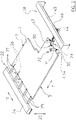
- 1 indicates, as a whole, a machine for manufacturing components C starting from a panel 2 of wood or the like of substantially rectangular shape limited by two major faces 3 parallel to each other, by two
- the device 22 comprises two longitudinal guide members 23 parallel with each other, which extend along the direction 7, that are arranged on opposite bands of the devices 8 and 9 in the direction 16, and support a crosspiece 24, which extends in the direction 16, and is slidingly coupled to the longitudinal members 23 to perform, with respect to the longitudinal members 23 themselves, rectilinear displacements in both directions of the direction 7.
- the device 22 also comprises a plurality of holding members 25, which are distributed along the crosspiece 24 to hold the panel 2 at one of the faces 4, and each comprise a respective lower jaw 26 and a respective upper jaw 27 movable between a clamping position and a release position of the panel 2.
- Each member 25 extends between two roller bars (not shown) of the device 8, and each jaw 26 extends below the plane P, and is aligned with a relative channel 14 in the direction 7.
- the machine 1 also comprises a second holding and transporting device 28, facing the panel 2 in direction 7.
- the device 28 comprises a crosspiece 43, which is supported by the longitudinal guide members 23, extends in the direction 16, and is slidingly coupled to the longitudinal members 23, in order to perform rectilinear displacements with respect to the longitudinal members 23 themselves in both directions of the direction 7.
- the device 28 further comprises, in this case, two slides 46 slidingly coupled to the crosspiece 43, to perform rectilinear displacements with respect to the crosspiece 43 in both directions of direction 16.
- the device 28 comprises in its turn two slides 44, which extend in the direction 7, that are slidingly coupled to the respective slides 46, to perform relative displacements with respect to slides 46 in the direction 7.
- the device 28 further comprises two holding devices 47 for the panel 2 slidingly coupled to the respective slides 44, to perform displacements along the direction 20, between a working position holding the panel 2 and a raised position, to allow the device 28 itself bypassing the component C transferred by it to the conveyor belt 11 and gripping the panel 2.
- the two holding devices 47 are, in this case, constituted by an upper jaw 29 and a lower jaw 30, movable between a clamping position and a release position of one of faces 4 (4*). It should be pointed out that the faces 4* are parallel or coincident with the face 4 of the panel 2 and are generated by the cuts of the panel 2 along direction 16.
- the machine 1 also comprises an operating unit 31, which is mounted in correspondence with the cutting channel 15, and has a crosspiece 32, which extends in the direction 16, and supports, in this case, an operating head 33.
- the head 33 is movable along the crosspiece 32 in the direction 16, and supports an electro-spindle 34, which extends in the direction 20, is coupled in a sliding manner to the head 33, to perform, with respect to the head 33 itself, rectilinear movements in the direction 20, and a tool 35 is engaged, aligned with the channel 15 in the direction 20.
- the electro-spindle 34 is arranged alongside the presser 36 in direction 7, which extends in direction 16, is mounted between the crosspiece 24 and the channel 15 in the direction 7, and is movable in the direction 20 between a clamping position, in which the panel 2 is blocked against the plane P to allow the tool 35 to work the panel 2 in the direction 16, and a release position.
- the tool 35 In use, by combining the displacements of the panel 2 in direction 7 with the displacements of the head 33 in direction 16, the tool 35 separates a plurality of components C from the panel 2.
- the presence of the holding device 28, in addition to the members 25, allows holding the panel 2 in correspondence with both faces 4 (4*), guarantees a correct action of the tool 35, and prevents the panel 2 from flexing laterally on the plane P, in particular when the tool 35 penetrates the panel 2, during the advancement of the panel along the direction 7; moreover it allows transferring the component C separated from the panel 2 onto the conveyor belt 11, keeping it on hold, with benefits in productivity and economy terms.
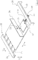
- FIG 7 differs from what is illustrated in figures 1 , 2 , 3 , 4 , and 6 only in that, in it, the operating head 33 is eliminated and replaced with two operating heads 38 movable along the crosspiece 32 in a manner independent of each other.
- Each head 38 supports an electro-spindle 39, which is completely similar to the electro-spindle 34, it has a tool 40 inserted completely similar to the tool 35.
- the tools 40 of the two heads 38 define two faces 42 of a component (not shown) parallel to each other and to direction 7 itself.
- the member 28 holds the panel 2, in correspondence with the faces 4 (4*) and guarantees a correct action of the tools 40 preventing the panel 2 from flexing laterally on the plane P, during the advancement of the panel 2 in direction 7.
- the device 28 consists of the device 45, namely, a suction blocking member in fluid dynamic communication with a suction device, through a supply duct.
Applications Claiming Priority (1)
| Application Number | Priority Date | Filing Date | Title |
|---|---|---|---|
| IT102020000024955A IT202000024955A1 (it) | 2020-10-22 | 2020-10-22 | Metodo e macchina per la realizzazione di componenti di legno o simili |
Publications (1)
| Publication Number | Publication Date |
|---|---|
| EP3988267A1 true EP3988267A1 (en) | 2022-04-27 |
Family
ID=74068603
Family Applications (1)
| Application Number | Title | Priority Date | Filing Date |
|---|---|---|---|
| EP21203173.6A Pending EP3988267A1 (en) | 2020-10-22 | 2021-10-18 | Method and machine to manufacture components made of wood or the like |
Country Status (2)
| Country | Link |
|---|---|
| EP (1) | EP3988267A1 (it) |
| IT (1) | IT202000024955A1 (it) |
Citations (5)
| Publication number | Priority date | Publication date | Assignee | Title |
|---|---|---|---|---|
| WO1992012816A1 (en) * | 1991-01-18 | 1992-08-06 | Hallvard Berge | A multispindle machine for processing workpieces gripped by independently controlled feeding and clamping means on either side of the tool assembly |
| DE10305570A1 (de) * | 2002-10-02 | 2004-04-15 | Hundegger Maschinenbau Hans | Verfahren und Bearbeitungsanlage für das Bearbeiten von Holzwerkstücken |
| EP1832402A1 (en) * | 2006-03-10 | 2007-09-12 | IMPRESA 2000 DI SACCHI PARIDE E C. s.a.s. | Shaping machine for longitudinally shaping component parts of wood or similar, in particular, component parts of door and window frames |
| EP2105269A2 (en) * | 2008-03-25 | 2009-09-30 | BIESSE S.p.A. | A method and machine for profiling elongated wood components or the like, specifically components for door and window frames |
| EP3117975A1 (en) * | 2015-07-14 | 2017-01-18 | G.P. Consulting di Giuseppe Pritelli & C. S.a.s. | Cutting machine, particularly for wooden panels and the like |
-
2020
- 2020-10-22 IT IT102020000024955A patent/IT202000024955A1/it unknown
-
2021
- 2021-10-18 EP EP21203173.6A patent/EP3988267A1/en active Pending
Patent Citations (5)
| Publication number | Priority date | Publication date | Assignee | Title |
|---|---|---|---|---|
| WO1992012816A1 (en) * | 1991-01-18 | 1992-08-06 | Hallvard Berge | A multispindle machine for processing workpieces gripped by independently controlled feeding and clamping means on either side of the tool assembly |
| DE10305570A1 (de) * | 2002-10-02 | 2004-04-15 | Hundegger Maschinenbau Hans | Verfahren und Bearbeitungsanlage für das Bearbeiten von Holzwerkstücken |
| EP1832402A1 (en) * | 2006-03-10 | 2007-09-12 | IMPRESA 2000 DI SACCHI PARIDE E C. s.a.s. | Shaping machine for longitudinally shaping component parts of wood or similar, in particular, component parts of door and window frames |
| EP2105269A2 (en) * | 2008-03-25 | 2009-09-30 | BIESSE S.p.A. | A method and machine for profiling elongated wood components or the like, specifically components for door and window frames |
| EP3117975A1 (en) * | 2015-07-14 | 2017-01-18 | G.P. Consulting di Giuseppe Pritelli & C. S.a.s. | Cutting machine, particularly for wooden panels and the like |
Also Published As
| Publication number | Publication date |
|---|---|
| IT202000024955A1 (it) | 2022-04-22 |
Similar Documents
| Publication | Publication Date | Title |
|---|---|---|
| EP3260234B1 (en) | Machine to process section bars | |
| CN108025451B (zh) | 一种用于对工件进行加工的加工设备 | |
| US10668643B2 (en) | Machining device | |
| US4392401A (en) | Apparatus for staggered cutting of planar workpieces | |
| JP4221199B2 (ja) | 木材やプラスチック材料の工作物を加工する機械及び方法 | |
| US4502585A (en) | Workpiece carrier locating and clamping mechanism for assembly line arrangement | |
| JP2003080434A5 (it) | ||
| KR101621065B1 (ko) | 프로파일의 펀칭 및 노칭 자동가공장치 | |
| CN109562431B (zh) | 用于机器的装载和卸载装置、用于加工板状工件的机器、用于这种机器的工件支撑件及装载和卸载这种机器的方法 | |
| US20190224790A1 (en) | Variable machine table | |
| EP2990147A1 (en) | Machine for cutting wood panels or the like | |
| CN107829222B (zh) | 一种自动抓料装置及具有其的缝纫设备 | |
| EP3061582B1 (en) | Cutting machine for cutting panels of wood or the like | |
| CA2671174A1 (en) | Device for conveying a workpiece | |
| EP2991811B1 (en) | Machining center | |
| EP3988267A1 (en) | Method and machine to manufacture components made of wood or the like | |
| CN113714619A (zh) | 一种焊接设备 | |
| EP3175950B1 (en) | Machine to process bars made of aluminium, light alloys, pvc or the like | |
| EP2110350B1 (en) | Apparatus for forming stacks of panels | |
| EP2159022A2 (en) | Planing machine for planing components made of wood or similar. | |
| EP3639957B1 (en) | Cutting machine to cut panels made of wood or the like | |
| EP3639994B1 (en) | Cutting machine to cut panels made of wood or the like | |
| CN108724359B (zh) | 改进的机床 | |
| ITBO20060471A1 (it) | Macchina sezionatrice per pannelli di legno o simili | |
| EP2246165B1 (en) | Working machine for wood or similar materials |
Legal Events
| Date | Code | Title | Description |
|---|---|---|---|
| PUAI | Public reference made under article 153(3) epc to a published international application that has entered the european phase |
Free format text: ORIGINAL CODE: 0009012 |
|
| STAA | Information on the status of an ep patent application or granted ep patent |
Free format text: STATUS: THE APPLICATION HAS BEEN PUBLISHED |
|
| AK | Designated contracting states |
Kind code of ref document: A1 Designated state(s): AL AT BE BG CH CY CZ DE DK EE ES FI FR GB GR HR HU IE IS IT LI LT LU LV MC MK MT NL NO PL PT RO RS SE SI SK SM TR |
|
| STAA | Information on the status of an ep patent application or granted ep patent |
Free format text: STATUS: REQUEST FOR EXAMINATION WAS MADE |
|
| 17P | Request for examination filed |
Effective date: 20220926 |
|
| RBV | Designated contracting states (corrected) |
Designated state(s): AL AT BE BG CH CY CZ DE DK EE ES FI FR GB GR HR HU IE IS IT LI LT LU LV MC MK MT NL NO PL PT RO RS SE SI SK SM TR |
|
| P01 | Opt-out of the competence of the unified patent court (upc) registered |
Effective date: 20230518 |