EP3986795B1 - System zum halbautomatischen schliessen von flexiblen behältern - Google Patents
System zum halbautomatischen schliessen von flexiblen behältern Download PDFInfo
- Publication number
- EP3986795B1 EP3986795B1 EP20740394.0A EP20740394A EP3986795B1 EP 3986795 B1 EP3986795 B1 EP 3986795B1 EP 20740394 A EP20740394 A EP 20740394A EP 3986795 B1 EP3986795 B1 EP 3986795B1
- Authority
- EP
- European Patent Office
- Prior art keywords
- web
- labeled
- closing
- labels
- container
- Prior art date
- Legal status (The legal status is an assumption and is not a legal conclusion. Google has not performed a legal analysis and makes no representation as to the accuracy of the status listed.)
- Active
Links
Images

Classifications
-
- B—PERFORMING OPERATIONS; TRANSPORTING
- B65—CONVEYING; PACKING; STORING; HANDLING THIN OR FILAMENTARY MATERIAL
- B65B—MACHINES, APPARATUS OR DEVICES FOR, OR METHODS OF, PACKAGING ARTICLES OR MATERIALS; UNPACKING
- B65B51/00—Devices for, or methods of, sealing or securing package folds or closures; Devices for gathering or twisting wrappers, or necks of bags
- B65B51/04—Applying separate sealing or securing members, e.g. clips
-
- B—PERFORMING OPERATIONS; TRANSPORTING
- B65—CONVEYING; PACKING; STORING; HANDLING THIN OR FILAMENTARY MATERIAL
- B65B—MACHINES, APPARATUS OR DEVICES FOR, OR METHODS OF, PACKAGING ARTICLES OR MATERIALS; UNPACKING
- B65B61/00—Auxiliary devices, not otherwise provided for, for operating on sheets, blanks, webs, binding material, containers or packages
- B65B61/04—Auxiliary devices, not otherwise provided for, for operating on sheets, blanks, webs, binding material, containers or packages for severing webs, or for separating joined packages
- B65B61/06—Auxiliary devices, not otherwise provided for, for operating on sheets, blanks, webs, binding material, containers or packages for severing webs, or for separating joined packages by cutting
-
- B—PERFORMING OPERATIONS; TRANSPORTING
- B65—CONVEYING; PACKING; STORING; HANDLING THIN OR FILAMENTARY MATERIAL
- B65B—MACHINES, APPARATUS OR DEVICES FOR, OR METHODS OF, PACKAGING ARTICLES OR MATERIALS; UNPACKING
- B65B63/00—Auxiliary devices, not otherwise provided for, for operating on articles or materials to be packaged
- B65B63/005—Auxiliary devices, not otherwise provided for, for operating on articles or materials to be packaged for marking or coding articles prior to packaging
-
- B—PERFORMING OPERATIONS; TRANSPORTING
- B65—CONVEYING; PACKING; STORING; HANDLING THIN OR FILAMENTARY MATERIAL
- B65C—LABELLING OR TAGGING MACHINES, APPARATUS, OR PROCESSES
- B65C7/00—Affixing tags
Definitions
- the present invention generally finds application in the field of flexible container packaging systems and particularly relates to a system for semi-automatically closing flexible containers.
- Containers made of a flexible material, such as plastic, paper and/or a biodegradable material, with an opening designed to allow introduction and/or removal of one or more products, and to be re-closed using a tie, a tape or any other rigid or semi-rigid closing sheet element, have been long known to be used in the field of packaging systems.
- the closing element is wrapped in such a manner as to allow a user to remove it to re-open the container and withdraw products through the opening.
- tapes or straps are known in the art, usually as clips, generally made of polymer or metal material, which are fed from a coil and cut to size immediately before the closing step, to encircle the container proximate the opening, and re-close it.
- a housing for a continuous web bobbin is located proximate the station and is unwound in a controlled manner using an intermittent driving disk, to move one portion of web of predetermined length at a time next to the closing station.
- the portion of the web that is intended to form the clip to be wound around the container is cut by means of cutting means having a blade that is movable against the closing web.
- the clip is pushed by deforming and closing means into the closing station, in which an abutment wall causes it to deform and encircle the container to close it.
- a first drawback of these known solutions is that the movements of the cutting, deforming and closing means are generally performed by pneumatic actuators controlled by a central control unit for controlling supply to the various devices, to coordinate their movements.
- pneumatic actuators generally release oily particles in the external environment, with the risk of air contamination.
- a further drawback of this solution is that the use of compressed air prevents accurate coordination of the movements of the various pneumatic actuators, resulting in the formation of clips having different lengths.
- the device may be only used to close pre-printed containers differing according to the type of products contained therein.
- JP2014006468 discloses a system for closing flexible containers by means of labeled clips that can be closed by bonding or interlocking using a system having a continuous deformable web and a device for closing containers with said web.
- a first drawback of this known solution is that the system is only used to close labeled clips of flexible type.
- US 3 973 294 discloses a closing web for packaging having integral labels spaced along the longitudinal extent of the web.
- DE 29600142 discloses a device for simultaneous application of a clip web and a label web separated from each other on objects or packages of various products.
- the technical problem addressed by the present invention is, in short, to provide a system for semi-automatically closing flexible containers by means of labeled clips that allows labels to be positioned at the center of each clip and each clip to be positioned at the center of the open end of each container to prevent label deformation.
- the object of the present invention is to obviate the above drawback, by providing a system for semi-automatically closing flexible containers, that is highly efficient and relatively cost-effective.
- a particular object of the present invention is to provide a system for semi-automatically closing flexible containers as described hereinbefore, that allows the label to be positioned at the center of the clip.
- a further object of the present invention is to provide a system for semi-automatically closing flexible containers as described hereinbefore that can effectively close the container.
- Another object of the present invention is to provide a system for semi-automatically closing flexible containers as described hereinbefore that allows synchronized actuation of its components by accurate, inexpensive means.
- a further object the present invention is to provide a system for semi-automatically closing flexible containers as described hereinbefore, that can avoid label deformation during processing.
- Yet another object of the present invention is to provide a system for semi-automatically closing flexible containers as described hereinbefore, that requires no particular operator skills during closing of the container.
- a further object of the present invention is to provide a system for semi-automatically closing flexible containers as described hereinbefore that has a small size.
- Another object of the present invention is to provide a system for semi-automatically closing flexible containers as described hereinbefore that can use labeled clips made of a material that can be printed, deformed by engraving or marking or labeled clips adapted to receive an adhesive.
- a system for semi-automatically closing flexible containers as defined in claim 1, which comprises a continuous deformable web a semi-automatic device for closing containers with the web.
- the device comprises a frame having a slot for receiving an open end of one container at a time, feeding means for feeding the web, cutting means for cutting the web and deforming and closing means.
- the web has labels integrally joined thereto at a substantially constant distance from each other, to thereby form a labeled web having a predetermined cross section
- the cutting means are configured to cut the web into sections whose length is equal to the distance and to form labeled clips with the labels located halfway of the sections.
- the deforming and closing means are coordinated with the cutting means to deform and close each labeled clip around the open end of one container at a time while keeping the labels centered on each container.
- the frame comprises a substantially horizontal plate with at least one vertical stiffening wall and the feeding means comprise a passage that extends along the wall and has a greater cross section than the labeled web to avoid any deformation of its labels as it is being fed.
- the system allows the container to be closed by the labeled clip with the label positioned at the center of the container and without no label deformation.
- the device comprises sensor means for detecting the position of the labeled web or each individual clip and for controlling actuation of the cutting means and the deforming and closing means in coordination with the feeding means to keep the labels at the center of each clip and each clip at the center of the open end of each container, as defined in claim 3.
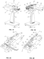
- a system for semi-automatically closing flexible containers generally designated by reference numeral 1, for closing containers C having an open end A for withdrawal of products contained therein.
- the containers C may be made of a flexible material, such as paper, plastic, and/or a degradable material and are designed to contain products of any kind, including food products, with no particular limitation.
- the system 1 comprises a bobbin B for receiving a deformable web N wound thereupon, which has a band 4 made of semi-rigid and deformable material with an upper edge 4A and a lower edge 4B designed to face the opening A and the bottom B of the container C respectively.
- the band 4 may be substantially flat and made of metal, for example aluminum, or paper or a polymeric material with thread-like cores 4C made of metal or non-metal material and extending along its entire length proximate the edges 4A, 4B to increase its rigidity, while maintaining its deformability.
- the system 1 comprises a semi-automatic device 2 for closing the containers C by means of the web N.
- the structure of the semi-automatic device 2 may be, for example but without limitation, as described and claimed in European Patent EP2665655 by the applicant hereof.
- the device 2 may be of portable type and adapted to be placed in any room with a connection to the mains or any other source of electric voltage and comprises a frame 5 adapted to be placed on a pedestal 5' resting on the ground G or, alternatively, the frame 5 may be placed on a supporting surface G.
- the frame 5 has a slot 6 formed therein for receiving the open end A of a one container C at a time and the device 2 comprises feeding means 7 for feeding the web N.
- the web has labels E integrally joined thereto at a substantially constant distance d from each other, to thereby form a labeled web N having a predetermined cross-section with a thickness s1 and a height h1.
- the labels E may have any plan shape, e.g. a circular or polygonal shape.
- the device 2 comprises cutting means 8 for cutting the web N into sections 4', 4" whose length 1 is equal to the distance d to form individual labeled clips 3, with the labels E kept halfway of the sections 4', 4".
- the length of the sections 4', 4" is equal to half the length I of each labeled clip 3.
- deforming and closing means 9 are provided downstream of the cutting means 8, for deforming and closing each labeled clip 3 around the open end A of one container C at a time, with the labels E kept centered on each container C.
- the deforming and closing means 9 are coordinated with the cutting means 8 and the feeding means 7 comprise, upstream from the cutting means 8 and the deforming and closing means 9, a passage 10 formed in the frame 5 to convey the labeled web N toward the aforementioned cutting means 8 and deforming and closing means 9.
- the device 2 further comprises: sensor means 11 for detecting the position of the labeled web N or each individual clip 3 and controlling the actuation of the cutting means 8 and the closing means 9 in coordination with the feeding means 7.
- system 1 can keep the labels E at the center of each clip 3 and each clip 3 at the center of the open end A of each container C, as better explained below.
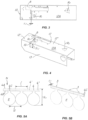
- the frame 5 comprises a substantially horizontal plate 12 with the slot 6 formed therein and the feeding means 7, the cutting means 8, the closing and deforming means 9 arranged thereon and with the passage 10 formed therein, as shown in FIGS. 3 and 4 .
- the passage 10 extends throughout the top surface 12A of the plate 12, thereby creating a separation between two flat surfaces 12', 12" thereof.
- the plate 12 has at least one vertical stiffening wall 13 located at one edge of the plate 12 and configured to join the flat portions 12', 12".
- the passage 10 is substantially uniform, extends along the stiffening wall 13 and has a cross-section having a width s2 and a height h2.
- the cross-section of the passage 10 is greater than the cross-section of the labeled web N to prevent the labels E from interfering with the frame 5 and from being deformed as the web N is being fed.
- both the width s2 and the height h2 of the passage 10 are greater than the thickness s1 and the height h1 of the labeled web N.
- the feeding means 7 may further comprise guide means 14 for the web N, which are adapted to unwind it from the bobbin B and guide it toward the passage 10 in a substantially vertical position and with the labels E facing the supporting surface G.
- the guide means 14 may comprise a plurality of vertically-extending rollers 15, mounted in opposed pairs, and of brass- or ball bearing-mounted type, each having a peripheral surface 15' designed to contact the web N at the band 4.
- the guide means 14 may comprise a pair of profiled elements 16 with mutually facing contact surfaces 16' configured to contact the web N at the band 4.
- both the peripheral surface 15' of the rollers 15 and the contact surface 16' of the profiled elements 16 may comprise corresponding horizontal recesses 15", 16" which are able to interact with the possible metal thread-like cores 4C in the band 4 of the clips 3.
- the system 1 comprises a first electric motor 17 for driving the feeding means 7 and a second electric motor 18 for driving the cutting means 8 and the deforming and closing means 9.
- the first motor 17 and the second motor 18 may be controlled by a central control unit U through sensor means 11 so that the second motor 18 will be actuated when the first motor 17 is idle and the web N is cut and later properly deformed.
- feeding means 7, the cutting means 8 and the deforming and closing means 9 may be driven by a single electric motor controlled by the central control unit U and through the sensor means 11, without departure from the scope of the present invention.
- the system 1 affords synchronized actuation of its parts using accurate and inexpensive means.
- the feeding means 7 comprise a driving disk 19 located proximate the passage 10 to interact with the web N from the bobbin B to transfer it from the guide means 14 to the cutting means 8 and to the deforming and closing means 9 in a substantially horizontal first direction X parallel to the passage 10 and to the top surface 12A of the plate 12, as better shown in FIGS. 2B , 3 and 4 .
- the feeding disc 19 may be adjacent to a friction disc 19' to form a sliding surface that is intended to contact the web N to cause it to slide and be unwound from the bobbin B.
- the two discs 19 and 19' may comprise a predetermined diameter ratio and may rotate about respective substantially parallel and vertical rotation axes.
- the feeding disc 19 will be a driving disc, whereas the friction disc 19' may be driven and idly or friction-mounted.
- the feeding disc 19 is keyed to the first motor 17 which comprises a first shaft rotating about a first, substantially vertical rotation axis R1.
- first motor 17 may be rigidly joined to a substantially flat element 20 mounted above or below the plate 12 and proximate the passage 10 to further stiffen the plate 12.
- the sensor means 11 may comprise at least one position sensor adapted to read the position of the driving disk 19 and to detect the position of the labeled web N, namely to read the position of the label E.
- the sensor means 11 may comprise an incremental or absolute encoder adapted to read the position of the shaft of the first motor 17 and detect the position of the labeled web N.
- the cutting means 8 comprise an elongate slider 21 intended to slide on brass bearings or recirculating-ball slide guides in a substantially horizontal second direction Y orthogonal to the first direction X and the plate 12 may comprise a cutting seat 22 located between the feeding disc 19 and the closing slot 6.
- the cutting means 8 may intercept the band 4 of the web N in the cutting seat 22, and cause its separation to form the labeled clip 3, as shown in FIG. 7A , which is then pushed into a forming seat 23, located at the slot 6, which is acted upon by the deforming and closing means 9, also movable in the second direction Y, as shown in FIG. 7C .
- the deforming and closing means 9 may comprise pre-shaping means 24 which act on the labeled clip 3 to form the sections 4', 4" with a substantial U shape having its concavity oriented in the second direction Y and facing the forming seat 23, as shown in FIG. 7B .
- a shaping element 25 may be provided inside the forming seat 23, with a substantially vertical abutment surface 25' transverse to the second direction Y and having curved walls adapted to deform the sections 4', 4" of the labeled clip 3 to wrap them around the container C, to thereby close the open end A.
- the slider 21 may be movable in the second direction Y between a first rearward end position and a second forward end position in which it interacts with the web N.
- the slider 21 has a first end 21' located proximate the slot 6 and a second end 21", opposite the first end 21' and driven by the second motor 18.
- the second motor 18 is located below the plate 12 and comprises a second shaft, rotating about a substantially vertical second rotation axis R2, and keyed to a transmission element 26, possibly with the interposition of a reduction gear, not shown.
- the transmission element 26 may comprise an articulated linkage 27 configured to move the slider 21 and transfer the motion of the second motor 18 to the latter and to allow coordinated movement of the cutting means 8, the pre-shaping means 24 and the deforming and closing means 9.
- a stamping station may be provided, which is mounted at the side of the plate 12 and has means for dispensing dyeing material to the label E or means for engraving the latter.
- an upper cover 5" may be provided, to protect the cutting means 8, the deforming and closing means 9 and, at least partially, the feeding means 7.
- system 1 of the invention affords semi-automatic closing of flexible containers C using labeled clips 3 made of a material that can be printed, deformed by engraving or marking or using labeled clips 3 adapted to receive an adhesive.
- the invention relates to a method of semi-automatically closing flexible containers C by means of a system 1 of the above discussed type.
- the method of the invention includes a first step a) of providing a continuous deformable web N for making clips 3 and a second step b) of integrally joining a plurality of labels E to the web N, at a substantially constant distance d from each other.
- the system for semi-automatically closing flexible containers fulfills the intended objects and namely allows the labels to be placed at the center of each clip and each clip to be placed at the center of the open end of each container.
- the present invention may find application in industry, because it can be produced on an industrial scale in factories operating in the field of flexible container packaging.
Landscapes
- Engineering & Computer Science (AREA)
- Mechanical Engineering (AREA)
- Labeling Devices (AREA)
- Threshing Machine Elements (AREA)
- Power-Operated Mechanisms For Wings (AREA)
Claims (11)
- Ein System (1) zum halbautomatischen Verschließen von flexiblen Behältern (C), das eine kontinuierliche verformbare Bahn (N) und eine halbautomatische Vorrichtung (2) zum Verschließen von Behältern (C) mit dieser Bahn (N) umfasst, wobei die Vorrichtung (2) einen Rahmen (5) mit einem Schlitz (6) zum Aufnehmen eines offenen Endes (A) eines Behälters (C) auf einmal, Zuführmittel (7) zum Zuführen der Bahn (N), Schneidmittel (8) zum Schneiden der Bahn (N) und Verformungs- und Verschlussmittel (9) umfasst,
dadurch gekennzeichnet, dass Etiketten (E) integral mit der Bahn (N) verbunden und in einem im Wesentlichen konstanten Abstand (d) voneinander angeordnet sind, um eine etikettierte Bahn mit einem vorgegebenen Querschnitt zu bilden, wobei die Schneidmittel (8) so konfiguriert sind, dass sie die Bahn (N) in Abschnitte (4', 4") schneiden, deren Länge (I) gleich dem Abstand (d) ist, und einzelne etikettierte Clips (3) bilden, während die Etiketten (E) auf halber Höhe der Abschnitte (4', 4") gehalten werden, wobei die Verformungs- und Verschlussmittel (9) koordiniert mit den Schneidmitteln (8) sind, um jeden etikettierten Clip (3) um das offene Ende (A) jeweils eines Behälters (C) zu verformen und zu schließen, während die Etiketten (E) auf jedem Behälter (C) zentriert gehalten werden, wobei der Rahmen (5) eine im Wesentlichen horizontale Platte (12) mit mindestens einer vertikalen Versteifungswand (13) und einem Durchgang (10) aufweist, der entlang der Wand (13) verläuft und einen größeren Querschnitt als die etikettierte Bahn (N) hat, um jede Verformung ihrer Etiketten (E) während der Zufuhr zu vermeiden. - System nach Anspruch 1, dadurch gekennzeichnet, dass der Durchgang (10) im Wesentlichen gleichmäßig ist und seine Breite (s2) größer als die Dicke (s1) der etikettierten Bahn (N) und seine Höhe (h2) größer als die Höhe (h1) der etikettierten Bahn (N) ist.
- System nach Anspruch 1, dadurch gekennzeichnet, dass die Vorrichtung (2) Sensormittel (11) zum Erfassen der Position der etikettierten Bahn (N) oder jedes einzelnen Clips (3) und zum Steuern der Betätigung der Schneidmittel (8) und der Verformungs- und Verschlussmittel (9) in Abstimmung mit den Zuführmitteln (7) umfasst, um die Etiketten (E) in der Mitte jedes Clips (3) und jeden Clip (3) in der Mitte des offenen Endes (A) jedes Behälters (C) zu halten.
- System nach Anspruch 1, dadurch gekennzeichnet, dass es einen ersten Elektromotor (17) zum Antreiben der Zuführmittel (7) und einen zweiten Elektromotor (18) zum Antreiben der Schneidmittel (8) und der Verformungs- und Verschlussmittel (9) umfasst.
- System nach Anspruch 4, dadurch gekennzeichnet, dass der erste Motor (17) starr mit einem im Wesentlichen flachen Element (20) verbunden ist, das sich über oder unter der Platte (12) und in der Nähe des Durchgangs (10) befindet, um die Platte (12) weiter zu versteifen.
- System nach Anspruch 4, dadurch gekennzeichnet, dass die Zuführmittel (7) eine Antriebsscheibe (19) umfassen, die sich in der Nähe des Durchgangs (10) befindet und so konfiguriert ist, dass sie mit der Bahn (N) interagiert, um sie in eine im Wesentlichen horizontale erste Richtung (X) und parallel zum Durchgang (10) und zur oberen Oberfläche (12A) der Platte (12) zu transportieren, wobei der erste Motor (17) eine erste Welle aufweist, die um eine im Wesentlichen vertikale erste Rotationsachse (R1) rotiert und mit der Antriebsscheibe (19) verkeilt ist.
- System nach Ansprüchen 3 und 6, dadurch gekennzeichnet, dass die Sensormittel (11) mindestens einen Positionssensor umfassen, der dazu geeignet ist, die Position der Antriebsscheibe (19) zu lesen und die Position der etikettierten Bahn (N) und/oder jedes einzelnen Etiketts (E) zu erfassen.
- System nach Anspruch 6, dadurch gekennzeichnet, dass die Sensormittel (11) einen inkrementellen oder absoluten Encoder umfassen, der dazu geeignet ist, die Position der Welle des ersten Motors (17) zu lesen und die Position der etikettierten Bahn (N) zu erfassen.
- System nach Anspruch 1, dadurch gekennzeichnet, dass es eine Spule (B) umfasst, auf die die etikettierte Bahn (N) gewickelt ist, wobei die Zuführeinrichtung (7) Führungseinrichtungen (14) für die Bahn (N) umfasst, um sie in Richtung des Durchgangs (10) zu führen.
- System nach Anspruch 9, dadurch gekennzeichnet, dass die Führungseinrichtungen (14) eine Vielzahl gegenüberliegender Rollen (15) vom Typ mit Messing- oder Kugellagern umfassen, wobei die gegenüberliegenden Rollen (15) jeweils eine Umfangsfläche (15') aufweisen, die für den Kontakt mit der Bahn (N) bestimmt ist.
- System nach Anspruch 9, dadurch gekennzeichnet, dass die Führungseinrichtungen (14) ein Paar einander zugewandter Profilflächen (16', 16") umfassen, die jeweils für den Kontakt mit der Bahn (N) bestimmt sind.
Applications Claiming Priority (2)
| Application Number | Priority Date | Filing Date | Title |
|---|---|---|---|
| IT102019000009780A IT201900009780A1 (it) | 2019-06-21 | 2019-06-21 | Sistema per la chiusura semiautomatica di contenitori flessibili e relativo metodo di chiusura |
| PCT/IB2020/055787 WO2020255064A1 (en) | 2019-06-21 | 2020-06-19 | System for semi-automatically closing flexible containers |
Publications (2)
| Publication Number | Publication Date |
|---|---|
| EP3986795A1 EP3986795A1 (de) | 2022-04-27 |
| EP3986795B1 true EP3986795B1 (de) | 2024-07-17 |
Family
ID=68234249
Family Applications (1)
| Application Number | Title | Priority Date | Filing Date |
|---|---|---|---|
| EP20740394.0A Active EP3986795B1 (de) | 2019-06-21 | 2020-06-19 | System zum halbautomatischen schliessen von flexiblen behältern |
Country Status (6)
| Country | Link |
|---|---|
| US (1) | US11970302B2 (de) |
| EP (1) | EP3986795B1 (de) |
| CN (1) | CN114514179B (de) |
| CA (1) | CA3143424A1 (de) |
| IT (1) | IT201900009780A1 (de) |
| WO (1) | WO2020255064A1 (de) |
Family Cites Families (10)
| Publication number | Priority date | Publication date | Assignee | Title |
|---|---|---|---|---|
| US3973294A (en) * | 1973-12-17 | 1976-08-10 | Walter Pfizenmaier | Closure strip for flexible-walled containers |
| DE29600142U1 (de) * | 1996-01-05 | 1996-03-28 | Hermann, Werner, 64743 Beerfelden | Vorrichtung zum Etikettieren von Ware |
| US6272815B1 (en) * | 1998-11-03 | 2001-08-14 | Klockner-Bartelt, Inc. | Servo-controlled pouch making apparatus |
| NZ544555A (en) * | 2001-05-01 | 2007-09-28 | Baumli P J | Methods and apparatus for producing and for applying labels to necks of bottles without separate support web |
| MX2009006423A (es) * | 2006-12-15 | 2009-09-02 | Ccl Label Gmbh | Aplicador de etiquetas tipo manga de pelicula estirable. |
| US20140339358A1 (en) * | 2007-12-06 | 2014-11-20 | Roller Bearing Company Of America, Inc. | Electrical conductor for lined track rollers used on actuation system for aircraft lift assisting devices |
| IT1401117B1 (it) * | 2010-07-14 | 2013-07-12 | Ilti S R L | Tamburo di taglio e trasferimento di etichette linerless da un nastro continuo ad un contenitore in movimento e apparecchiatura dotata di tale tamburo. |
| ITVI20110008A1 (it) | 2011-01-21 | 2012-07-22 | Comi Pak Engineering S R L Unipers Onale | Macchina per la chiusura di contenitori flessibili |
| JP2014006468A (ja) | 2012-06-27 | 2014-01-16 | Mopac Corp | タグ又はラベル付き袋口結束テープ |
| JP6302258B2 (ja) * | 2014-01-20 | 2018-03-28 | 株式会社イシダ | 製袋包装機 |
-
2019
- 2019-06-21 IT IT102019000009780A patent/IT201900009780A1/it unknown
-
2020
- 2020-06-19 CN CN202080058569.7A patent/CN114514179B/zh active Active
- 2020-06-19 EP EP20740394.0A patent/EP3986795B1/de active Active
- 2020-06-19 CA CA3143424A patent/CA3143424A1/en active Pending
- 2020-06-19 US US17/618,093 patent/US11970302B2/en active Active
- 2020-06-19 WO PCT/IB2020/055787 patent/WO2020255064A1/en not_active Ceased
Also Published As
| Publication number | Publication date |
|---|---|
| US20220297864A1 (en) | 2022-09-22 |
| CN114514179A (zh) | 2022-05-17 |
| IT201900009780A1 (it) | 2020-12-21 |
| CA3143424A1 (en) | 2020-12-24 |
| WO2020255064A1 (en) | 2020-12-24 |
| EP3986795A1 (de) | 2022-04-27 |
| US11970302B2 (en) | 2024-04-30 |
| CN114514179B (zh) | 2024-05-24 |
Similar Documents
| Publication | Publication Date | Title |
|---|---|---|
| EP2233399B1 (de) | Horizontale Verpackungsmaschine mit einem Abwickler mit einer Spleißvorrichtung zum Tauschen der Rollen ohne ein Anhalten der Maschine sowie eine mit besagter Maschine verwendbare Bandzuführeinheit | |
| EP3478589B1 (de) | Etikettierungsvorrichtung | |
| US20070163207A1 (en) | Adhesive tape applying machine for use with a stretch wrapper | |
| CN111542477B (zh) | 用于将标签施加到香烟包装件上的方法和设备 | |
| JP2006510514A (ja) | 緩衝材製品の製造方法、装置およびシステム、ならびにそのロール伸張器 | |
| US20230048955A1 (en) | Web processing machine | |
| EP3986795B1 (de) | System zum halbautomatischen schliessen von flexiblen behältern | |
| EP2226255B1 (de) | Vorrichtung und Verfahren zum Verschliessen von Beuteln | |
| EP2437983B1 (de) | Stanzeinheit und verfahren zur verpackung eines produkts mit einer solchen stanzeinheit | |
| EP2662321A2 (de) | Filmkassette | |
| RU2802574C2 (ru) | Система для полуавтоматического закрытия эластичных контейнеров | |
| CN113148364B (zh) | 一种c形半环绕式的自动贴标机 | |
| CN102958625A (zh) | 用于构成带环的配置单元和用于制造易拉盖的方法和装置 | |
| EP3448762B1 (de) | Vertikale verpackungsmaschine | |
| US20020065181A1 (en) | Process and apparatus for producing packs with an outer wrapper as well as reel unit | |
| US20130199128A1 (en) | Printer with Split Platen for Printing Web Material and Method | |
| NL2005579C2 (nl) | Werkwijze en inrichting voor het verpakken van een product en een verpakt product. | |
| US20060065371A1 (en) | Automatic labeling machine for containers | |
| EP2665655B1 (de) | Maschine zum verschliessen flexibler behälter | |
| JP2016513051A (ja) | 容器にテーピングするための方法及び装置 | |
| FI121371B (fi) | Menetelmä ja laitteisto sulkuliuskan asettamiseksi | |
| US4979348A (en) | Sealing film applying machine, adapted for packaging parcels, books, signatures and brochures, even individually, by means of a wrapping web | |
| EP3119681B1 (de) | System zur positionierung eines etikeiits auf einer verpackung | |
| KR101888757B1 (ko) | 식품포장이 용이한 포장지 및 그 성형장치 | |
| EP2711322A1 (de) | Puffervorrichtung zur Handhabung eines Materials in Form einer Bahn |
Legal Events
| Date | Code | Title | Description |
|---|---|---|---|
| STAA | Information on the status of an ep patent application or granted ep patent |
Free format text: STATUS: UNKNOWN |
|
| STAA | Information on the status of an ep patent application or granted ep patent |
Free format text: STATUS: THE INTERNATIONAL PUBLICATION HAS BEEN MADE |
|
| PUAI | Public reference made under article 153(3) epc to a published international application that has entered the european phase |
Free format text: ORIGINAL CODE: 0009012 |
|
| STAA | Information on the status of an ep patent application or granted ep patent |
Free format text: STATUS: REQUEST FOR EXAMINATION WAS MADE |
|
| 17P | Request for examination filed |
Effective date: 20220118 |
|
| AK | Designated contracting states |
Kind code of ref document: A1 Designated state(s): AL AT BE BG CH CY CZ DE DK EE ES FI FR GB GR HR HU IE IS IT LI LT LU LV MC MK MT NL NO PL PT RO RS SE SI SK SM TR |
|
| DAV | Request for validation of the european patent (deleted) | ||
| DAX | Request for extension of the european patent (deleted) | ||
| GRAP | Despatch of communication of intention to grant a patent |
Free format text: ORIGINAL CODE: EPIDOSNIGR1 |
|
| STAA | Information on the status of an ep patent application or granted ep patent |
Free format text: STATUS: GRANT OF PATENT IS INTENDED |
|
| INTG | Intention to grant announced |
Effective date: 20240213 |
|
| GRAS | Grant fee paid |
Free format text: ORIGINAL CODE: EPIDOSNIGR3 |
|
| GRAA | (expected) grant |
Free format text: ORIGINAL CODE: 0009210 |
|
| STAA | Information on the status of an ep patent application or granted ep patent |
Free format text: STATUS: THE PATENT HAS BEEN GRANTED |
|
| AK | Designated contracting states |
Kind code of ref document: B1 Designated state(s): AL AT BE BG CH CY CZ DE DK EE ES FI FR GB GR HR HU IE IS IT LI LT LU LV MC MK MT NL NO PL PT RO RS SE SI SK SM TR |
|
| REG | Reference to a national code |
Ref country code: CH Ref legal event code: EP |
|
| REG | Reference to a national code |
Ref country code: DE Ref legal event code: R096 Ref document number: 602020034127 Country of ref document: DE |
|
| REG | Reference to a national code |
Ref country code: IE Ref legal event code: FG4D |
|
| REG | Reference to a national code |
Ref country code: LT Ref legal event code: MG9D |
|
| REG | Reference to a national code |
Ref country code: NL Ref legal event code: MP Effective date: 20240717 |
|
| PG25 | Lapsed in a contracting state [announced via postgrant information from national office to epo] |
Ref country code: PT Free format text: LAPSE BECAUSE OF FAILURE TO SUBMIT A TRANSLATION OF THE DESCRIPTION OR TO PAY THE FEE WITHIN THE PRESCRIBED TIME-LIMIT Effective date: 20241118 |
|
| REG | Reference to a national code |
Ref country code: AT Ref legal event code: MK05 Ref document number: 1703910 Country of ref document: AT Kind code of ref document: T Effective date: 20240717 |
|
| PG25 | Lapsed in a contracting state [announced via postgrant information from national office to epo] |
Ref country code: NL Free format text: LAPSE BECAUSE OF FAILURE TO SUBMIT A TRANSLATION OF THE DESCRIPTION OR TO PAY THE FEE WITHIN THE PRESCRIBED TIME-LIMIT Effective date: 20240717 |
|
| PG25 | Lapsed in a contracting state [announced via postgrant information from national office to epo] |
Ref country code: PT Free format text: LAPSE BECAUSE OF FAILURE TO SUBMIT A TRANSLATION OF THE DESCRIPTION OR TO PAY THE FEE WITHIN THE PRESCRIBED TIME-LIMIT Effective date: 20241118 Ref country code: NL Free format text: LAPSE BECAUSE OF FAILURE TO SUBMIT A TRANSLATION OF THE DESCRIPTION OR TO PAY THE FEE WITHIN THE PRESCRIBED TIME-LIMIT Effective date: 20240717 |
|
| PG25 | Lapsed in a contracting state [announced via postgrant information from national office to epo] |
Ref country code: NO Free format text: LAPSE BECAUSE OF FAILURE TO SUBMIT A TRANSLATION OF THE DESCRIPTION OR TO PAY THE FEE WITHIN THE PRESCRIBED TIME-LIMIT Effective date: 20241017 |
|
| PG25 | Lapsed in a contracting state [announced via postgrant information from national office to epo] |
Ref country code: FI Free format text: LAPSE BECAUSE OF FAILURE TO SUBMIT A TRANSLATION OF THE DESCRIPTION OR TO PAY THE FEE WITHIN THE PRESCRIBED TIME-LIMIT Effective date: 20240717 Ref country code: PL Free format text: LAPSE BECAUSE OF FAILURE TO SUBMIT A TRANSLATION OF THE DESCRIPTION OR TO PAY THE FEE WITHIN THE PRESCRIBED TIME-LIMIT Effective date: 20240717 Ref country code: GR Free format text: LAPSE BECAUSE OF FAILURE TO SUBMIT A TRANSLATION OF THE DESCRIPTION OR TO PAY THE FEE WITHIN THE PRESCRIBED TIME-LIMIT Effective date: 20241018 |
|
| PG25 | Lapsed in a contracting state [announced via postgrant information from national office to epo] |
Ref country code: BG Free format text: LAPSE BECAUSE OF FAILURE TO SUBMIT A TRANSLATION OF THE DESCRIPTION OR TO PAY THE FEE WITHIN THE PRESCRIBED TIME-LIMIT Effective date: 20240717 |
|
| PG25 | Lapsed in a contracting state [announced via postgrant information from national office to epo] |
Ref country code: LV Free format text: LAPSE BECAUSE OF FAILURE TO SUBMIT A TRANSLATION OF THE DESCRIPTION OR TO PAY THE FEE WITHIN THE PRESCRIBED TIME-LIMIT Effective date: 20240717 |
|
| PG25 | Lapsed in a contracting state [announced via postgrant information from national office to epo] |
Ref country code: IS Free format text: LAPSE BECAUSE OF FAILURE TO SUBMIT A TRANSLATION OF THE DESCRIPTION OR TO PAY THE FEE WITHIN THE PRESCRIBED TIME-LIMIT Effective date: 20241117 Ref country code: AT Free format text: LAPSE BECAUSE OF FAILURE TO SUBMIT A TRANSLATION OF THE DESCRIPTION OR TO PAY THE FEE WITHIN THE PRESCRIBED TIME-LIMIT Effective date: 20240717 |
|
| PG25 | Lapsed in a contracting state [announced via postgrant information from national office to epo] |
Ref country code: HR Free format text: LAPSE BECAUSE OF FAILURE TO SUBMIT A TRANSLATION OF THE DESCRIPTION OR TO PAY THE FEE WITHIN THE PRESCRIBED TIME-LIMIT Effective date: 20240717 |
|
| PG25 | Lapsed in a contracting state [announced via postgrant information from national office to epo] |
Ref country code: ES Free format text: LAPSE BECAUSE OF FAILURE TO SUBMIT A TRANSLATION OF THE DESCRIPTION OR TO PAY THE FEE WITHIN THE PRESCRIBED TIME-LIMIT Effective date: 20240717 Ref country code: RS Free format text: LAPSE BECAUSE OF FAILURE TO SUBMIT A TRANSLATION OF THE DESCRIPTION OR TO PAY THE FEE WITHIN THE PRESCRIBED TIME-LIMIT Effective date: 20241017 |
|
| PG25 | Lapsed in a contracting state [announced via postgrant information from national office to epo] |
Ref country code: RS Free format text: LAPSE BECAUSE OF FAILURE TO SUBMIT A TRANSLATION OF THE DESCRIPTION OR TO PAY THE FEE WITHIN THE PRESCRIBED TIME-LIMIT Effective date: 20241017 Ref country code: PL Free format text: LAPSE BECAUSE OF FAILURE TO SUBMIT A TRANSLATION OF THE DESCRIPTION OR TO PAY THE FEE WITHIN THE PRESCRIBED TIME-LIMIT Effective date: 20240717 Ref country code: NO Free format text: LAPSE BECAUSE OF FAILURE TO SUBMIT A TRANSLATION OF THE DESCRIPTION OR TO PAY THE FEE WITHIN THE PRESCRIBED TIME-LIMIT Effective date: 20241017 Ref country code: LV Free format text: LAPSE BECAUSE OF FAILURE TO SUBMIT A TRANSLATION OF THE DESCRIPTION OR TO PAY THE FEE WITHIN THE PRESCRIBED TIME-LIMIT Effective date: 20240717 Ref country code: IS Free format text: LAPSE BECAUSE OF FAILURE TO SUBMIT A TRANSLATION OF THE DESCRIPTION OR TO PAY THE FEE WITHIN THE PRESCRIBED TIME-LIMIT Effective date: 20241117 Ref country code: HR Free format text: LAPSE BECAUSE OF FAILURE TO SUBMIT A TRANSLATION OF THE DESCRIPTION OR TO PAY THE FEE WITHIN THE PRESCRIBED TIME-LIMIT Effective date: 20240717 Ref country code: GR Free format text: LAPSE BECAUSE OF FAILURE TO SUBMIT A TRANSLATION OF THE DESCRIPTION OR TO PAY THE FEE WITHIN THE PRESCRIBED TIME-LIMIT Effective date: 20241018 Ref country code: FI Free format text: LAPSE BECAUSE OF FAILURE TO SUBMIT A TRANSLATION OF THE DESCRIPTION OR TO PAY THE FEE WITHIN THE PRESCRIBED TIME-LIMIT Effective date: 20240717 Ref country code: ES Free format text: LAPSE BECAUSE OF FAILURE TO SUBMIT A TRANSLATION OF THE DESCRIPTION OR TO PAY THE FEE WITHIN THE PRESCRIBED TIME-LIMIT Effective date: 20240717 Ref country code: BG Free format text: LAPSE BECAUSE OF FAILURE TO SUBMIT A TRANSLATION OF THE DESCRIPTION OR TO PAY THE FEE WITHIN THE PRESCRIBED TIME-LIMIT Effective date: 20240717 Ref country code: AT Free format text: LAPSE BECAUSE OF FAILURE TO SUBMIT A TRANSLATION OF THE DESCRIPTION OR TO PAY THE FEE WITHIN THE PRESCRIBED TIME-LIMIT Effective date: 20240717 |
|
| PG25 | Lapsed in a contracting state [announced via postgrant information from national office to epo] |
Ref country code: SM Free format text: LAPSE BECAUSE OF FAILURE TO SUBMIT A TRANSLATION OF THE DESCRIPTION OR TO PAY THE FEE WITHIN THE PRESCRIBED TIME-LIMIT Effective date: 20240717 Ref country code: RO Free format text: LAPSE BECAUSE OF FAILURE TO SUBMIT A TRANSLATION OF THE DESCRIPTION OR TO PAY THE FEE WITHIN THE PRESCRIBED TIME-LIMIT Effective date: 20240717 Ref country code: DK Free format text: LAPSE BECAUSE OF FAILURE TO SUBMIT A TRANSLATION OF THE DESCRIPTION OR TO PAY THE FEE WITHIN THE PRESCRIBED TIME-LIMIT Effective date: 20240717 |
|
| REG | Reference to a national code |
Ref country code: DE Ref legal event code: R097 Ref document number: 602020034127 Country of ref document: DE |
|
| PG25 | Lapsed in a contracting state [announced via postgrant information from national office to epo] |
Ref country code: EE Free format text: LAPSE BECAUSE OF FAILURE TO SUBMIT A TRANSLATION OF THE DESCRIPTION OR TO PAY THE FEE WITHIN THE PRESCRIBED TIME-LIMIT Effective date: 20240717 |
|
| PG25 | Lapsed in a contracting state [announced via postgrant information from national office to epo] |
Ref country code: CZ Free format text: LAPSE BECAUSE OF FAILURE TO SUBMIT A TRANSLATION OF THE DESCRIPTION OR TO PAY THE FEE WITHIN THE PRESCRIBED TIME-LIMIT Effective date: 20240717 |
|
| PG25 | Lapsed in a contracting state [announced via postgrant information from national office to epo] |
Ref country code: SK Free format text: LAPSE BECAUSE OF FAILURE TO SUBMIT A TRANSLATION OF THE DESCRIPTION OR TO PAY THE FEE WITHIN THE PRESCRIBED TIME-LIMIT Effective date: 20240717 |
|
| PLBE | No opposition filed within time limit |
Free format text: ORIGINAL CODE: 0009261 |
|
| STAA | Information on the status of an ep patent application or granted ep patent |
Free format text: STATUS: NO OPPOSITION FILED WITHIN TIME LIMIT |
|
| 26N | No opposition filed |
Effective date: 20250422 |
|
| PG25 | Lapsed in a contracting state [announced via postgrant information from national office to epo] |
Ref country code: SE Free format text: LAPSE BECAUSE OF FAILURE TO SUBMIT A TRANSLATION OF THE DESCRIPTION OR TO PAY THE FEE WITHIN THE PRESCRIBED TIME-LIMIT Effective date: 20240717 |
|
| REG | Reference to a national code |
Ref country code: DE Ref legal event code: R119 Ref document number: 602020034127 Country of ref document: DE |
|
| REG | Reference to a national code |
Ref country code: CH Ref legal event code: H13 Free format text: ST27 STATUS EVENT CODE: U-0-0-H10-H13 (AS PROVIDED BY THE NATIONAL OFFICE) Effective date: 20260127 |
|
| PG25 | Lapsed in a contracting state [announced via postgrant information from national office to epo] |
Ref country code: MC Free format text: LAPSE BECAUSE OF FAILURE TO SUBMIT A TRANSLATION OF THE DESCRIPTION OR TO PAY THE FEE WITHIN THE PRESCRIBED TIME-LIMIT Effective date: 20240717 |
|
| PG25 | Lapsed in a contracting state [announced via postgrant information from national office to epo] |
Ref country code: LU Free format text: LAPSE BECAUSE OF NON-PAYMENT OF DUE FEES Effective date: 20250619 |
|
| GBPC | Gb: european patent ceased through non-payment of renewal fee |
Effective date: 20250619 |
|
| REG | Reference to a national code |
Ref country code: BE Ref legal event code: MM Effective date: 20250630 |
|
| PG25 | Lapsed in a contracting state [announced via postgrant information from national office to epo] |
Ref country code: GB Free format text: LAPSE BECAUSE OF NON-PAYMENT OF DUE FEES Effective date: 20250619 |
|
| PG25 | Lapsed in a contracting state [announced via postgrant information from national office to epo] |
Ref country code: DE Free format text: LAPSE BECAUSE OF NON-PAYMENT OF DUE FEES Effective date: 20260101 Ref country code: IE Free format text: LAPSE BECAUSE OF NON-PAYMENT OF DUE FEES Effective date: 20250619 |
|
| PG25 | Lapsed in a contracting state [announced via postgrant information from national office to epo] |
Ref country code: IT Free format text: LAPSE BECAUSE OF NON-PAYMENT OF DUE FEES Effective date: 20250619 Ref country code: BE Free format text: LAPSE BECAUSE OF NON-PAYMENT OF DUE FEES Effective date: 20250630 |
|
| PG25 | Lapsed in a contracting state [announced via postgrant information from national office to epo] |
Ref country code: FR Free format text: LAPSE BECAUSE OF NON-PAYMENT OF DUE FEES Effective date: 20250630 |
|
| PG25 | Lapsed in a contracting state [announced via postgrant information from national office to epo] |
Ref country code: CH Free format text: LAPSE BECAUSE OF NON-PAYMENT OF DUE FEES Effective date: 20250630 |