EP2665655B1 - Maschine zum verschliessen flexibler behälter - Google Patents
Maschine zum verschliessen flexibler behälter Download PDFInfo
- Publication number
- EP2665655B1 EP2665655B1 EP12705421.1A EP12705421A EP2665655B1 EP 2665655 B1 EP2665655 B1 EP 2665655B1 EP 12705421 A EP12705421 A EP 12705421A EP 2665655 B1 EP2665655 B1 EP 2665655B1
- Authority
- EP
- European Patent Office
- Prior art keywords
- band
- machine
- shaping
- cutting
- closing
- Prior art date
- Legal status (The legal status is an assumption and is not a legal conclusion. Google has not performed a legal analysis and makes no representation as to the accuracy of the status listed.)
- Active
Links
Images
Classifications
-
- B—PERFORMING OPERATIONS; TRANSPORTING
- B65—CONVEYING; PACKING; STORING; HANDLING THIN OR FILAMENTARY MATERIAL
- B65B—MACHINES, APPARATUS OR DEVICES FOR, OR METHODS OF, PACKAGING ARTICLES OR MATERIALS; UNPACKING
- B65B51/00—Devices for, or methods of, sealing or securing package folds or closures; Devices for gathering or twisting wrappers, or necks of bags
- B65B51/04—Applying separate sealing or securing members, e.g. clips
-
- B—PERFORMING OPERATIONS; TRANSPORTING
- B65—CONVEYING; PACKING; STORING; HANDLING THIN OR FILAMENTARY MATERIAL
- B65B—MACHINES, APPARATUS OR DEVICES FOR, OR METHODS OF, PACKAGING ARTICLES OR MATERIALS; UNPACKING
- B65B65/00—Details peculiar to packaging machines and not otherwise provided for; Arrangements of such details
- B65B65/02—Driving gear
-
- B—PERFORMING OPERATIONS; TRANSPORTING
- B65—CONVEYING; PACKING; STORING; HANDLING THIN OR FILAMENTARY MATERIAL
- B65B—MACHINES, APPARATUS OR DEVICES FOR, OR METHODS OF, PACKAGING ARTICLES OR MATERIALS; UNPACKING
- B65B67/00—Apparatus or devices facilitating manual packaging operations; Sack holders
- B65B67/02—Packaging of articles or materials in containers
- B65B67/06—Manually-operable devices for closing bag necks, by applying and securing lengths of string, wire or tape
Definitions
- the present invention generally finds application in the field of product packaging machines and particularly relates to a machine for closing flexible containers.
- containers or bags made of flexible material such as plastic or paper, which have a neck with an opening designed to allow introduction and/or removal of one or more products, and to be re-closed using a tie, a band or any other rigid or semirigid sheet element.
- the latter is wrapped in such a manner as to allow a user to re-open the bag and withdraw products through the opening.
- bands or straps usually known as clips, generally made of polymer or metal material, which are fed from a coil and cut to size immediately before the closing step, to encircle the bag neck, proximate the opening, and re-close it.
- bag closing machines having a frame with a station for manual positioning of the bag neck, in which the closing step is carried out.
- a housing for a closing band coil is located proximate the station and is unwound in a controlled manner using an intermittently-driven friction disk, to move one portion of predetermined length at a time next to the closing station.
- the portion designed to encircle the bag neck is cut by a blade which is movable perpendicular to the closing band.
- the cut portion is pushed by the blade into the closing station, in which an abutment wall causes it to deform and encircle the bag neck, to close it.
- a control unit may be provided for controlling air supply to the various devices, to coordinate their movements.
- US 1 493 075 discloses a machine for closing flexible containers having a stationary frame and all the features mentioned in the preamble of claim 1.
- This known machine is configured for closing bags having a mouth with no neck, and provides a means for gathering the portion of the bag close to the mouth before inserting it into a slot. Moreover the machine is actuated by a treadle.
- US 3 455 010 discloses a bag clip applicator having means for compressing the portion of the bag close to the mouth and for securing a closure member about the compressed portion.
- the object of the present invention is to obviate the above drawbacks, by providing a machine for closing flexible containers that is highly efficient and relatively cost-effective.
- a particular object is to provide a machine for closing flexible containers that is portable and may be installed in any room, without requiring the provision of a compressed air supply unit beforehand.
- a further object is to provide a machine for closing flexible containers that ensures synchronous movement of its parts using accurate and inexpensive means.
- a machine of the invention may be used to re-close containers or bags C made of polymeric material, paper or metal material, which have a neck N with an opening A for withdrawing products therefrom.
- the containers C may be designed to contain products of any type, possibly food, with no particular limitation.
- the machine 1 of the invention is portable and can be located in any room having a connection to the mains or any other voltage source.
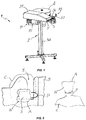
- the machine 1 comprises a supporting frame 2 which can be installed on a floor and has a shaping or closing seat 3, allowing the neck N of the container C to be manually placed and closed therein.
- the shaping seat 3 is located at the end of a slot 3' formed in the frame 2 to allow the neck N of the container C to be slid into the shaping seat 3.
- the frame 2 also has a support 4 for a reel B of a band E or any other substantially band-shaped closing sheet element having suitable stiffness and deformability.
- Such element may be substantially flat and made from a metal material, such as aluminum, or even a polymeric material, possibly with wire cores extending therethrough to increase its rigidity, while maintaining its deformability.
- the closing band E may have a width of a few millimeters, e.g. from 3 mm to 10 mm.
- closing band E is indicated by way of example only and without limitation to the present invention, and that any commercially available closing element may be used therein.
- the frame 2 further comprises a substantially horizontal support plate 5 having means 6 thereon for feeding the band E by unwinding the reel B and for guiding a portion P of the band E of predetermined length I to a cutting seat 7 located on the same plate 5, and in which the portion P of the band E to be cut will be substantially vertical.
- the feeding means 6 are designed to translate at least one end section of the reel B in a first predetermined direction X substantially parallel to the top surface 8 of the plate 5.
- the plate 5 is preferably, but not necessarily horizontal.
- the machine 1 further comprises cutting and pre-shaping means 9 for cutting and pre-shaping the portion P of the band E.
- the cutting and pre-shaping means 9 are designed to operate in a second direction Y, to capture the portion P of the band E contained in the cutting seat 7, cause its separation from the reel B and push it into the shaping seat 3.
- Second shaping means 10 are provided in the shaping seat 3 and in the plate 5, which are adapted to deform the cut and pre-shaped portion P and wrap it around the neck N of the container C, to close its opening A.
- Both the means 6 for feeding and guiding the band E and the cutting means 9 are driven by actuator means 11 that are directly mounted to the frame 2 and impart respective movements to such means.
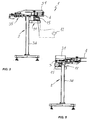
- the actuator means 11 are solely driven by a motor 15 and are designed to be connected to a voltage source 12, schematically shown in Fig. 2 , to be solely supplied with voltage.
- the actuator means 11 are operatively connected to the feeding means 6 and the cutting means 9 through first and second transmission means 13 and 14 respectively.
- the actuator means 11 include an electric motor 15 mounted to the frame 2 in any position and having a power supply.
- the motor 15 may be designed to be connected to any external voltage source 12, such as the mains in the premises in which the machine 1 is located from time to time, a voltage generator, possibly of movable type, or may be also powered by batteries.
- any external voltage source 12 such as the mains in the premises in which the machine 1 is located from time to time, a voltage generator, possibly of movable type, or may be also powered by batteries.
- the motor 15 has a power drive shaft, not shown, whose output is connected to the feeding means 6 and the cutting means 9 through the first and second transmission means 13, 14 respectively.
- These means 13, 14 are designed to convert the rotary motion of the power drive shaft into respective movements of the feeding means 6 and cutting means 9.
- a kinematic linkage 16 is provided, for mutually connecting the first transmission means 13 and the second transmission means 14 and to connect them to the electric motor 15, for synchronized drive thereof.
- the kinematic linkage 16 is designed to allow coordinated movement of the cutting means 9 and the feeding means 6.
- the kinematic linkage 16 may be designed to allow at least partially simultaneous movement of the feeding means 6 and the cutting means 9.
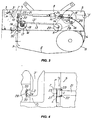
- the feeding and guide means 6 include a pulling element 17 which is designed to engage the portion P of the band E and carry it into the cutting station 7.
- the pulling element 17 includes a pair of friction disks 18 and 19 having respective peripheral sliding surfaces which are designed to contact opposite faces of the band E to assist sliding thereof and unwinding of the reel B.
- the two disks 18 and 19, which may have any diameter ratio therebetween, are adapted to rotate about first substantially parallel axes of rotation W, Z respectively, which are substantially vertical in the illustrated configuration.
- a first disk 18 is a driving disk, and the other 19 may be driven and idly or frictionally mounted about its axis Z.
- the driving disk 18 is connected to the actuator means 11, e.g. to the power drive shaft of the motor 15, through the first transmission means 13.
- the latter may include a first transmission element 20 interacting with the power drive shaft of the motor 15 through the kinematic linkage 16 and is adapted to rotate about a second axis of rotation K, substantially parallel to the first axes of rotation W, Z.
- the first transmission means 13 include a first mechanism 13', e.g. a linkage, such as a crank-slider, cam, crank, or similar mechanism, to transfer the rotary motion of the first transmission element 20 to the driving disk 18 and cause unwinding of the reel B.
- a first mechanism 13' e.g. a linkage, such as a crank-slider, cam, crank, or similar mechanism, to transfer the rotary motion of the first transmission element 20 to the driving disk 18 and cause unwinding of the reel B.
- the cutting means 9 may include an elongate slider 21, which is designed to slide in a second direction Y above and parallel to the top surface 8 of the support plate 5.
- the first direction X and the second direction Y are substantially orthogonal to each other.
- the slider 21 is designed to move between a first rearward, inoperative limit position and a second forward limit position, in which it interacts with the portion P of the band E contained in the cutting station 7 to force it into the shaping seat 3.
- the slider 21 has a substantially vertical blade 23 at its free end 22, and is connected at the other end 24 to the actuator means 11 through the second transmission means 14.
- the kinematic linkage 16 may be adjusted for the starting section of the travel of the slider 21 from the first limit position to the cutting seat 7 to be covered at the same time as the band E is unwound, thereby reducing cycle times.
- the second motion transmission means 14 may include a second transmission element 25 adapted to rotate about a third axis of rotation R which may be, by way of example, substantially parallel to the second axis of rotation K.
- a second mechanism 14' also possibly a linkage, which connects the second transmission element 25 with the end 24 of the slider 21, to transfer the rotary motion of the motor 15 thereto and convert it into a reciprocating translational motion of the slider 21 in the second direction Y.
- the transmission elements 20, 25 may consist of friction disks or gear wheels or more complex gearing systems, e.g. bevel gears, according to the direction in which the power drive shaft of the motor 15 extends.
- the kinematic synchronization linkage 16 may include an annular connection element 26, such as a drive belt or chain, which partially encircles the peripheral surfaces of the transmission elements 20, 25 to cause coordinated movement thereof.
- one of the two transmission elements 20, 25, e.g. the second 25, may be directly connected with the power drive shaft, possibly through an intervening transmission or gearmotor, not shown, whereas the connection of the other transmission element 25, 20 with the power drive shaft is obtained through the annular connection element 26.
- the sizes of the transmission elements 20, 25 and the connection element 26, as well as their relative positions, will allow coordination of the movements of the cutting means 9 and the feeding means 6, according to arrangements known to the skilled person, which will not be described in further detail.
- the second shaping means 10 may include a first shaping member 27 located in the cutting seat 7 and designed to impart a substantially U shape to the previously cut portion P of the band E, with the concave side facing towards the shaping seat 3.
- the latter will in turn accommodate a second shaping element 28 having a substantially vertical abutment surface 29 transverse to the second direction Y with convex transverse ends 30.
- the frame 2 may comprise a closing lid 31, which may be hinged to the support plate 5 or otherwise placed thereon to protect both the cutting means 9 and at least part of the feeding means 6, e.g. the friction disks 18 and 19. Conversely, the shaping seat 3 is located outside the lid 31.
- the latter will have a lateral aperture 32 for receiving the band E and a front aperture 33 for ejecting the blade 23 of the slider 21 and for allowing the cut portion P of the band E to move from the cutting seat 7 to the shaping aseat 3.
- the frame 2 also comprises a support column 34 for permanent or removable installation thereof on the floor of the room, for easy transportation thereof.
- the machine 1 may also include a stamping station 35 mounted at the side of the plate 5, which has means 36 for delivering a dyeing material, such as an ink or the like, to a transfer element 37 for transferring the dyeing material to the closing band E.
- a stamping station 35 mounted at the side of the plate 5, which has means 36 for delivering a dyeing material, such as an ink or the like, to a transfer element 37 for transferring the dyeing material to the closing band E.
- the transfer element 37 will pivot about a fourth axis of rotation between a first dyeing material withdrawing position to a second transfer position, in which it contacts a face of the closing band E, to transfer text, e.g. a date, or an image thereto.
- the fourth axis of rotation which may be substantially vertical, may be driven independent of the feeding means 6 and/or the cutting means 9.
- the same actuator means 11 e.g. the same power drive shaft of the common electric motor 15
- third motion transmission means possibly connected to the first and second motion transmission means 13, 14 through the kinematic linkage 16.
- the actuator means 11 are actuated, e.g. by a simple switch or another control, which cause the power drive shaft to rotate and the cutting means 9 and the feeding means 6 to move in synchronism.
- the slider 21 is translated in the second direction Y to carry the blade 23 into the cutting seat 7 and contact the portion P.
- the blade 23 cuts the portion P of predetermined length I and continues its travel while pulling it first against the first shaping element 27 and then into the closing seat 7 until it contacts the abutment surface 29 of the second shaping element 28.
- the U-shaped portion P has a pair of arms that are pushed against respective convex portions 30 of the abutment surface 29 to encircle the neck N of the container C and re-close it.
- the stamping step if any, may be carried out before cutting.
- the invention fulfills the intended objects and particularly provides a machine for closing flexible containers that is portable and may be used in any room, without requiring the provision of a compressed air supply unit, but only the connection to a voltage source, such as the mains in the room.
Landscapes
- Engineering & Computer Science (AREA)
- Mechanical Engineering (AREA)
- Auxiliary Devices For And Details Of Packaging Control (AREA)
- Control And Other Processes For Unpacking Of Materials (AREA)
- Supplying Of Containers To The Packaging Station (AREA)
- Package Closures (AREA)
Claims (9)
- Eine Maschine zum Verschließen flexibler Behälter, wobei jeder Behälter (C) eine Öffnung (A) aufweist zur Aufnahme der darin enthaltenen Erzeugnisse und jeder Behälter einen Ansatz (N) aufweist für den Verschluss der Öffnung (A), der Behälter (C) von einem halbsteifen und verformbaren Verschlussband (E) zu schließen ist, wobei die Maschine umfasst:- einen Stützrahmen (2),- eine Platte (5),- eine Spule (B), auf die das verformbare Verschlussband (E) aufgewickelt ist,- wobei die Platte (5) einen Schlitz (3') aufweist für das sofortige Einfügen des Ansatzes (N) des Behälters (20) nahe zu seiner Öffnung (A),- eine formende Anlage (3) zum Formen des Verschlussbands (E),- eine schneidende Anlage (7) zum Schneiden eines Abschnitts (P) des Verschlussbands (E) auf eine vorbestimmte Länge,- Zufuhreinrichtungen (6) für die Zufuhr des Bands (E) in die schneidende Anlage (7) entlang einer ersten Richtung (X),- Einrichtungen (9) zum Schneiden und Formen des Abschnitts (P) des Bands (E),- Betätigungseinrichtungen (11) zum Bewegen der Zufuhreinrichtungen (6) und der Einrichtungen (9) zum Schneiden und Formen,dadurch gekennzeichnet, dass
die Platte (5) horizontal ist und verankert ist an dem Stützrahmen (2),- der Schlitz (3') ein Ende aufweist und die Anlage (3) zum Formen an diesem Ende des Schlitzes (3') angeordnet ist, und zum Einfügen des Ansatzes (N) des Behälters (C) ist, wobei die Anlage (3) zum Formen auch zum Positionieren und Schließen des Ansatzes (N) des Behälters (C) ist- die Einrichtungen (9) zum Schneiden und Formen des Abschnitts (P) des Bands (E) in der schneidenden Anlage (7) angeordnet sind,- die Betätigungseinrichtungen (11) ausschließlich mittels einem elektrischen Motor (15) betätigt werden,- die erste Richtung (X) zur Zufuhr des Bands (E) im Wesentlichen parallel ist zu der oberen Fläche der Platte (5), die Einrichtungen (9) zum Schneiden und Formen einen länglichen Schlitten (21) umfassen, der ausgelegt ist für das Gleiten in eine zweite Richtung (Y), die im Wesentlichen horizontal und rechtwinklig ist zu der ersten Richtung (X), um die Einrichtungen (9) zum Schneiden und Formen in die schneidende Anlage (7) zu befördern und den Bandabschnitt (P) zu berühren, um den Bandabschnitt (P) zu schneiden, den geschnittenen Abschnitt (P) in die formende Anlage (3) zu zwingen und ihn um den Ansatz (N) des Behälters (C) zu schließen. - Maschine gemäß Anspruch 1, dadurch gekennzeichnet, dass der elektrische Motor (15) auf dem Rahmen (2) montiert ist.
- Maschine gemäß Anspruch 1, dadurch gekennzeichnet, dass die Betätigungseinrichtungen (11) erste und zweite Übertragungseinrichtungen (13, 14) umfassen, die ausgelegt sind, den Motor jeweils mit den Zufuhreinrichtungen (6) zu verbinden und mit den ersten Einrichtungen (9) zum Schneiden und Vorformen und den zweiten Einrichtungen (10) zum Formen, wobei die ersten und zweiten Übertragungseinrichtungen (13, 14) synchronisiert sind mittels einer kinematischen Verbindung (16).
- Maschine gemäß einem vorhergehenden Anspruch, dadurch gekennzeichnet, dass die Zufuhreinrichtungen (6) ein Zugelement (17) umfassen, das ausgelegt ist mit dem Verschlussband (E) zusammen zu wirken um es entlang der ersten Richtung (X) zu bewegen und um den zu schneidenden Abschnitt (P) in die schneidende Anlage (7) zu bringen.
- Maschine gemäß Anspruch 4, dadurch gekennzeichnet, dass das Zugelement (17) mindestens eine erste Reibscheibe (18) aufweist, die drehbar ist um eine erste Drehachse (W) und eine periphere, äußere Fläche hat, die ausgelegt ist, um in Anlage zu kommen mit einer Fläche des Verschlussbands (E), wobei die erste Reibscheibe (18) mechanisch verbunden ist mit den ersten Bewegungs-Übertragungseinrichtungen (13).
- Maschine gemäß Anspruch 5, dadurch gekennzeichnet, dass die ersten Bewegungs-Übertragungseinrichtungen (13) ein erstes Übertragungselement (20) umfassen, das mit dem Motor (15) zusammen wirkt und drehbar ist um eine zweite Drehachse (K) und eine erste gelenkige, kinematische Bewegung (13'), die ausgelegt ist, das erste Übertragungselement (20) mit der ersten Reibscheibe (18) zu verbinden und dahin die Bewegung des Motors (15) zu übertragen.
- Maschine gemäß einem der Ansprüche 3 bis 6, dadurch gekennzeichnet, dass der Schlitten (21) beweglich ist zwischen einer rückwärtigen Endposition und einer vorderen Endposition, wobei er mit dem Abschnitt (P) des Bands (E) zusammen wirkt, wobei der Schlitten (21) ein gegenüber liegendes Ende (24) hat, das an den zweiten Bewegungs-Übertragungseinrichtungen (14) befestigt ist zur Aufnahme der Bewegung von den Betätigungseinrichtungen (11).
- Maschine gemäß Anspruch 7, dadurch gekennzeichnet, dass die zweiten Bewegungs-Übertragungseinrichtungen (14) ein zweites Übertragungselement (25) umfassen, das drehbar ist um eine dritte Drehachse (R) und mit dem Motor (15) zusammen wirkt und eine zweite gelenkige, kinematische Bewegung (14'), die ausgelegt ist, das zweite Übertragungselement (25) mit dem Schlitten (21) zu verbinden, um dahin die Bewegung des Motors (15) zu übertragen.
- Maschine gemäß Anspruch 8, dadurch gekennzeichnet, dass die kinematische Verbindung (16) mindestens ein ringartiges Verbindungselement (26) aufweist, das funktional verbunden ist mit den ersten und zweiten Übertragungselementen (20, 25).
Priority Applications (3)
| Application Number | Priority Date | Filing Date | Title |
|---|---|---|---|
| HRP20161175TT HRP20161175T1 (hr) | 2011-01-21 | 2012-01-20 | Uređaj za zatvaranje fleksibilnih spremnika |
| SI201230711A SI2665655T1 (sl) | 2011-01-21 | 2012-01-20 | Stroj za zapiranje fleksibilnih posod |
| RS20160761A RS55160B1 (sr) | 2011-01-21 | 2012-01-20 | Uređaj za zatvaranje fleksibilnih kontejnera |
Applications Claiming Priority (2)
| Application Number | Priority Date | Filing Date | Title |
|---|---|---|---|
| IT000008A ITVI20110008A1 (it) | 2011-01-21 | 2011-01-21 | Macchina per la chiusura di contenitori flessibili |
| PCT/IB2012/050280 WO2012098526A1 (en) | 2011-01-21 | 2012-01-20 | Machine for closing flexible containers |
Publications (2)
| Publication Number | Publication Date |
|---|---|
| EP2665655A1 EP2665655A1 (de) | 2013-11-27 |
| EP2665655B1 true EP2665655B1 (de) | 2016-06-15 |
Family
ID=43975698
Family Applications (1)
| Application Number | Title | Priority Date | Filing Date |
|---|---|---|---|
| EP12705421.1A Active EP2665655B1 (de) | 2011-01-21 | 2012-01-20 | Maschine zum verschliessen flexibler behälter |
Country Status (10)
| Country | Link |
|---|---|
| EP (1) | EP2665655B1 (de) |
| ES (1) | ES2594771T3 (de) |
| HR (1) | HRP20161175T1 (de) |
| HU (1) | HUE030482T2 (de) |
| IT (1) | ITVI20110008A1 (de) |
| PL (1) | PL2665655T3 (de) |
| RS (1) | RS55160B1 (de) |
| RU (1) | RU2581875C2 (de) |
| SI (1) | SI2665655T1 (de) |
| WO (1) | WO2012098526A1 (de) |
Families Citing this family (2)
| Publication number | Priority date | Publication date | Assignee | Title |
|---|---|---|---|---|
| CN104029875A (zh) * | 2014-06-17 | 2014-09-10 | 河南科技大学 | 电动扎口机 |
| IT201900009780A1 (it) | 2019-06-21 | 2020-12-21 | Comi Pak Eng S R L Unipersonale | Sistema per la chiusura semiautomatica di contenitori flessibili e relativo metodo di chiusura |
Citations (4)
| Publication number | Priority date | Publication date | Assignee | Title |
|---|---|---|---|---|
| US3381359A (en) * | 1966-04-08 | 1968-05-07 | Paul G.K. Schroeder | Casing fastening machine |
| DE1461767A1 (de) * | 1967-10-05 | 1969-03-13 | Heinz Roedel | Vorrichtung zur Herstellung von Metallbandverschluessen an Verpackungen aus schlauchfoermigem Verpackungsmaterial |
| US3455010A (en) * | 1966-08-22 | 1969-07-15 | Amp Inc | Bag clip applicator |
| US20070130885A1 (en) * | 2005-12-08 | 2007-06-14 | Hickey Charles P | Bagging station |
Family Cites Families (4)
| Publication number | Priority date | Publication date | Assignee | Title |
|---|---|---|---|---|
| US1493075A (en) * | 1919-03-22 | 1924-05-06 | Millie Patent Holding Co Inc | Bag-closing machine |
| DE2105569B1 (de) * | 1971-02-06 | 1972-07-13 | Mega-Clip Vertriebs GmbH, 4795 Delbrück | Bundklammergerät |
| FR2484364A1 (fr) * | 1980-06-17 | 1981-12-18 | Transmeca Etude | Machine d'emballage avec mecanisme d'entrainement continu utilisant des cartons a plat |
| DE3331504A1 (de) * | 1983-06-04 | 1984-12-06 | Georg Hartmann Maschinenbau GmbH, 4795 Delbrück | Beutel-verschliessvorrichtung |
-
2011
- 2011-01-21 IT IT000008A patent/ITVI20110008A1/it unknown
-
2012
- 2012-01-20 PL PL12705421T patent/PL2665655T3/pl unknown
- 2012-01-20 SI SI201230711A patent/SI2665655T1/sl unknown
- 2012-01-20 HR HRP20161175TT patent/HRP20161175T1/hr unknown
- 2012-01-20 HU HUE12705421A patent/HUE030482T2/en unknown
- 2012-01-20 RU RU2013138603/13A patent/RU2581875C2/ru active
- 2012-01-20 EP EP12705421.1A patent/EP2665655B1/de active Active
- 2012-01-20 RS RS20160761A patent/RS55160B1/sr unknown
- 2012-01-20 WO PCT/IB2012/050280 patent/WO2012098526A1/en not_active Ceased
- 2012-01-20 ES ES12705421.1T patent/ES2594771T3/es active Active
Patent Citations (4)
| Publication number | Priority date | Publication date | Assignee | Title |
|---|---|---|---|---|
| US3381359A (en) * | 1966-04-08 | 1968-05-07 | Paul G.K. Schroeder | Casing fastening machine |
| US3455010A (en) * | 1966-08-22 | 1969-07-15 | Amp Inc | Bag clip applicator |
| DE1461767A1 (de) * | 1967-10-05 | 1969-03-13 | Heinz Roedel | Vorrichtung zur Herstellung von Metallbandverschluessen an Verpackungen aus schlauchfoermigem Verpackungsmaterial |
| US20070130885A1 (en) * | 2005-12-08 | 2007-06-14 | Hickey Charles P | Bagging station |
Also Published As
| Publication number | Publication date |
|---|---|
| RS55160B1 (sr) | 2017-01-31 |
| RU2013138603A (ru) | 2015-02-27 |
| ES2594771T3 (es) | 2016-12-22 |
| SI2665655T1 (sl) | 2017-02-28 |
| ITVI20110008A1 (it) | 2012-07-22 |
| HUE030482T2 (en) | 2017-05-29 |
| PL2665655T3 (pl) | 2017-02-28 |
| HRP20161175T1 (hr) | 2016-11-04 |
| EP2665655A1 (de) | 2013-11-27 |
| WO2012098526A1 (en) | 2012-07-26 |
| RU2581875C2 (ru) | 2016-04-20 |
Similar Documents
| Publication | Publication Date | Title |
|---|---|---|
| US8584438B2 (en) | Apparatuses and methods for applying a strap around a bundle of objects | |
| EP3303145B1 (de) | Umwicklungsmaschine | |
| WO2005085070A1 (en) | Banding system and process for banding piled products | |
| EP2665655B1 (de) | Maschine zum verschliessen flexibler behälter | |
| US8938935B2 (en) | Two-in-one bagger | |
| CN101160238A (zh) | 用于将产品包装在密封薄膜中的旋转头机器 | |
| KR102024720B1 (ko) | 접착테이프 디스펜서 | |
| CN215530295U (zh) | 一种用于捆扎机的卷线器及具有该卷线器的捆扎机 | |
| ES2208570T3 (es) | Procedimiento y sistema para el embalaje automatico continuo de productos. | |
| US20160362207A1 (en) | Method of packing piece goods and device for its implementation | |
| EP3986795B1 (de) | System zum halbautomatischen schliessen von flexiblen behältern | |
| JP4560188B2 (ja) | 三角柱状製品の包装機 | |
| CN211033302U (zh) | 一种手套折叠包装机 | |
| EP1608559B1 (de) | Vorrichtung zum anbringen von bindfäden an süssigkeiten | |
| RU2004128406A (ru) | Машина для нанесения этикеток на емкости | |
| HK1138817B (en) | Apparatus and method for applying a strap around a bundle of objects | |
| NL9001391A (nl) | Werkwijze voor het vervaardigen van een flexibele slang en inrichting voor het uitvoeren van deze werkwijze. |
Legal Events
| Date | Code | Title | Description |
|---|---|---|---|
| PUAI | Public reference made under article 153(3) epc to a published international application that has entered the european phase |
Free format text: ORIGINAL CODE: 0009012 |
|
| 17P | Request for examination filed |
Effective date: 20130722 |
|
| AK | Designated contracting states |
Kind code of ref document: A1 Designated state(s): AL AT BE BG CH CY CZ DE DK EE ES FI FR GB GR HR HU IE IS IT LI LT LU LV MC MK MT NL NO PL PT RO RS SE SI SK SM TR |
|
| DAX | Request for extension of the european patent (deleted) | ||
| 17Q | First examination report despatched |
Effective date: 20140702 |
|
| GRAP | Despatch of communication of intention to grant a patent |
Free format text: ORIGINAL CODE: EPIDOSNIGR1 |
|
| INTG | Intention to grant announced |
Effective date: 20160118 |
|
| GRAS | Grant fee paid |
Free format text: ORIGINAL CODE: EPIDOSNIGR3 |
|
| GRAA | (expected) grant |
Free format text: ORIGINAL CODE: 0009210 |
|
| AK | Designated contracting states |
Kind code of ref document: B1 Designated state(s): AL AT BE BG CH CY CZ DE DK EE ES FI FR GB GR HR HU IE IS IT LI LT LU LV MC MK MT NL NO PL PT RO RS SE SI SK SM TR |
|
| REG | Reference to a national code |
Ref country code: GB Ref legal event code: FG4D Ref country code: CH Ref legal event code: EP |
|
| REG | Reference to a national code |
Ref country code: IE Ref legal event code: FG4D |
|
| REG | Reference to a national code |
Ref country code: AT Ref legal event code: REF Ref document number: 806376 Country of ref document: AT Kind code of ref document: T Effective date: 20160715 |
|
| REG | Reference to a national code |
Ref country code: DE Ref legal event code: R096 Ref document number: 602012019545 Country of ref document: DE |
|
| REG | Reference to a national code |
Ref country code: HR Ref legal event code: TUEP Ref document number: P20161175 Country of ref document: HR Ref country code: RO Ref legal event code: EPE |
|
| REG | Reference to a national code |
Ref country code: NL Ref legal event code: FP |
|
| REG | Reference to a national code |
Ref country code: LT Ref legal event code: MG4D |
|
| PG25 | Lapsed in a contracting state [announced via postgrant information from national office to epo] |
Ref country code: NO Free format text: LAPSE BECAUSE OF FAILURE TO SUBMIT A TRANSLATION OF THE DESCRIPTION OR TO PAY THE FEE WITHIN THE PRESCRIBED TIME-LIMIT Effective date: 20160915 Ref country code: LT Free format text: LAPSE BECAUSE OF FAILURE TO SUBMIT A TRANSLATION OF THE DESCRIPTION OR TO PAY THE FEE WITHIN THE PRESCRIBED TIME-LIMIT Effective date: 20160615 |
|
| REG | Reference to a national code |
Ref country code: HR Ref legal event code: T1PR Ref document number: P20161175 Country of ref document: HR |
|
| REG | Reference to a national code |
Ref country code: AT Ref legal event code: MK05 Ref document number: 806376 Country of ref document: AT Kind code of ref document: T Effective date: 20160615 |
|
| PG25 | Lapsed in a contracting state [announced via postgrant information from national office to epo] |
Ref country code: SE Free format text: LAPSE BECAUSE OF FAILURE TO SUBMIT A TRANSLATION OF THE DESCRIPTION OR TO PAY THE FEE WITHIN THE PRESCRIBED TIME-LIMIT Effective date: 20160615 Ref country code: LV Free format text: LAPSE BECAUSE OF FAILURE TO SUBMIT A TRANSLATION OF THE DESCRIPTION OR TO PAY THE FEE WITHIN THE PRESCRIBED TIME-LIMIT Effective date: 20160615 |
|
| REG | Reference to a national code |
Ref country code: ES Ref legal event code: FG2A Ref document number: 2594771 Country of ref document: ES Kind code of ref document: T3 Effective date: 20161222 |
|
| REG | Reference to a national code |
Ref country code: FR Ref legal event code: PLFP Year of fee payment: 6 |
|
| PG25 | Lapsed in a contracting state [announced via postgrant information from national office to epo] |
Ref country code: EE Free format text: LAPSE BECAUSE OF FAILURE TO SUBMIT A TRANSLATION OF THE DESCRIPTION OR TO PAY THE FEE WITHIN THE PRESCRIBED TIME-LIMIT Effective date: 20160615 Ref country code: IS Free format text: LAPSE BECAUSE OF FAILURE TO SUBMIT A TRANSLATION OF THE DESCRIPTION OR TO PAY THE FEE WITHIN THE PRESCRIBED TIME-LIMIT Effective date: 20161015 |
|
| PG25 | Lapsed in a contracting state [announced via postgrant information from national office to epo] |
Ref country code: BE Free format text: LAPSE BECAUSE OF FAILURE TO SUBMIT A TRANSLATION OF THE DESCRIPTION OR TO PAY THE FEE WITHIN THE PRESCRIBED TIME-LIMIT Effective date: 20160615 Ref country code: PT Free format text: LAPSE BECAUSE OF FAILURE TO SUBMIT A TRANSLATION OF THE DESCRIPTION OR TO PAY THE FEE WITHIN THE PRESCRIBED TIME-LIMIT Effective date: 20161017 Ref country code: SM Free format text: LAPSE BECAUSE OF FAILURE TO SUBMIT A TRANSLATION OF THE DESCRIPTION OR TO PAY THE FEE WITHIN THE PRESCRIBED TIME-LIMIT Effective date: 20160615 Ref country code: AT Free format text: LAPSE BECAUSE OF FAILURE TO SUBMIT A TRANSLATION OF THE DESCRIPTION OR TO PAY THE FEE WITHIN THE PRESCRIBED TIME-LIMIT Effective date: 20160615 |
|
| REG | Reference to a national code |
Ref country code: GR Ref legal event code: EP Ref document number: 20160402238 Country of ref document: GR Effective date: 20170117 |
|
| REG | Reference to a national code |
Ref country code: DE Ref legal event code: R097 Ref document number: 602012019545 Country of ref document: DE |
|
| PLBE | No opposition filed within time limit |
Free format text: ORIGINAL CODE: 0009261 |
|
| STAA | Information on the status of an ep patent application or granted ep patent |
Free format text: STATUS: NO OPPOSITION FILED WITHIN TIME LIMIT |
|
| 26N | No opposition filed |
Effective date: 20170316 |
|
| REG | Reference to a national code |
Ref country code: HU Ref legal event code: AG4A Ref document number: E030482 Country of ref document: HU |
|
| PG25 | Lapsed in a contracting state [announced via postgrant information from national office to epo] |
Ref country code: DK Free format text: LAPSE BECAUSE OF FAILURE TO SUBMIT A TRANSLATION OF THE DESCRIPTION OR TO PAY THE FEE WITHIN THE PRESCRIBED TIME-LIMIT Effective date: 20160615 |
|
| PG25 | Lapsed in a contracting state [announced via postgrant information from national office to epo] |
Ref country code: MC Free format text: LAPSE BECAUSE OF FAILURE TO SUBMIT A TRANSLATION OF THE DESCRIPTION OR TO PAY THE FEE WITHIN THE PRESCRIBED TIME-LIMIT Effective date: 20160615 |
|
| REG | Reference to a national code |
Ref country code: IE Ref legal event code: MM4A |
|
| PG25 | Lapsed in a contracting state [announced via postgrant information from national office to epo] |
Ref country code: LU Free format text: LAPSE BECAUSE OF NON-PAYMENT OF DUE FEES Effective date: 20170120 |
|
| REG | Reference to a national code |
Ref country code: FR Ref legal event code: PLFP Year of fee payment: 7 |
|
| PG25 | Lapsed in a contracting state [announced via postgrant information from national office to epo] |
Ref country code: IE Free format text: LAPSE BECAUSE OF NON-PAYMENT OF DUE FEES Effective date: 20170120 |
|
| PG25 | Lapsed in a contracting state [announced via postgrant information from national office to epo] |
Ref country code: MT Free format text: LAPSE BECAUSE OF NON-PAYMENT OF DUE FEES Effective date: 20170120 |
|
| PG25 | Lapsed in a contracting state [announced via postgrant information from national office to epo] |
Ref country code: AL Free format text: LAPSE BECAUSE OF FAILURE TO SUBMIT A TRANSLATION OF THE DESCRIPTION OR TO PAY THE FEE WITHIN THE PRESCRIBED TIME-LIMIT Effective date: 20160615 |
|
| REG | Reference to a national code |
Ref country code: HR Ref legal event code: ODRP Ref document number: P20161175 Country of ref document: HR Payment date: 20190107 Year of fee payment: 8 |
|
| PG25 | Lapsed in a contracting state [announced via postgrant information from national office to epo] |
Ref country code: CY Free format text: LAPSE BECAUSE OF NON-PAYMENT OF DUE FEES Effective date: 20160615 |
|
| REG | Reference to a national code |
Ref country code: HR Ref legal event code: ODRP Ref document number: P20161175 Country of ref document: HR Payment date: 20200103 Year of fee payment: 9 |
|
| REG | Reference to a national code |
Ref country code: HR Ref legal event code: ODRP Ref document number: P20161175 Country of ref document: HR Payment date: 20210105 Year of fee payment: 10 |
|
| REG | Reference to a national code |
Ref country code: HR Ref legal event code: ODRP Ref document number: P20161175 Country of ref document: HR Payment date: 20220105 Year of fee payment: 11 |
|
| REG | Reference to a national code |
Ref country code: HR Ref legal event code: ODRP Ref document number: P20161175 Country of ref document: HR Payment date: 20230104 Year of fee payment: 12 |
|
| P01 | Opt-out of the competence of the unified patent court (upc) registered |
Effective date: 20231013 |
|
| REG | Reference to a national code |
Ref country code: HR Ref legal event code: ODRP Ref document number: P20161175 Country of ref document: HR Payment date: 20240104 Year of fee payment: 13 |
|
| REG | Reference to a national code |
Ref country code: HR Ref legal event code: ODRP Ref document number: P20161175 Country of ref document: HR Payment date: 20250120 Year of fee payment: 14 |
|
| PGFP | Annual fee paid to national office [announced via postgrant information from national office to epo] |
Ref country code: BG Payment date: 20250122 Year of fee payment: 14 |
|
| PGFP | Annual fee paid to national office [announced via postgrant information from national office to epo] |
Ref country code: MK Payment date: 20250120 Year of fee payment: 14 |
|
| PGFP | Annual fee paid to national office [announced via postgrant information from national office to epo] |
Ref country code: SI Payment date: 20251230 Year of fee payment: 15 |
|
| REG | Reference to a national code |
Ref country code: CH Ref legal event code: U11 Free format text: ST27 STATUS EVENT CODE: U-0-0-U10-U11 (AS PROVIDED BY THE NATIONAL OFFICE) Effective date: 20260201 |
|
| REG | Reference to a national code |
Ref country code: HR Ref legal event code: ODRP Ref document number: P20161175 Country of ref document: HR Payment date: 20260113 Year of fee payment: 15 |
|
| PGFP | Annual fee paid to national office [announced via postgrant information from national office to epo] |
Ref country code: NL Payment date: 20260126 Year of fee payment: 15 |
|
| PGFP | Annual fee paid to national office [announced via postgrant information from national office to epo] |
Ref country code: HU Payment date: 20260109 Year of fee payment: 15 |
|
| PGFP | Annual fee paid to national office [announced via postgrant information from national office to epo] |
Ref country code: GB Payment date: 20260127 Year of fee payment: 15 |
|
| PGFP | Annual fee paid to national office [announced via postgrant information from national office to epo] |
Ref country code: ES Payment date: 20260202 Year of fee payment: 15 |
|
| PGFP | Annual fee paid to national office [announced via postgrant information from national office to epo] |
Ref country code: DE Payment date: 20260128 Year of fee payment: 15 |
|
| PGFP | Annual fee paid to national office [announced via postgrant information from national office to epo] |
Ref country code: HR Payment date: 20260113 Year of fee payment: 15 |
|
| PGFP | Annual fee paid to national office [announced via postgrant information from national office to epo] |
Ref country code: FI Payment date: 20260126 Year of fee payment: 15 Ref country code: RO Payment date: 20260113 Year of fee payment: 15 Ref country code: IT Payment date: 20260123 Year of fee payment: 15 |
|
| PGFP | Annual fee paid to national office [announced via postgrant information from national office to epo] |
Ref country code: RS Payment date: 20260105 Year of fee payment: 15 |
|
| PGFP | Annual fee paid to national office [announced via postgrant information from national office to epo] |
Ref country code: FR Payment date: 20260126 Year of fee payment: 15 |
|
| PGFP | Annual fee paid to national office [announced via postgrant information from national office to epo] |
Ref country code: TR Payment date: 20260116 Year of fee payment: 15 |
|
| PGFP | Annual fee paid to national office [announced via postgrant information from national office to epo] |
Ref country code: CH Payment date: 20260201 Year of fee payment: 15 Ref country code: CZ Payment date: 20260107 Year of fee payment: 15 |
|
| PGFP | Annual fee paid to national office [announced via postgrant information from national office to epo] |
Ref country code: GR Payment date: 20260127 Year of fee payment: 15 Ref country code: PL Payment date: 20260102 Year of fee payment: 15 |
|
| PGFP | Annual fee paid to national office [announced via postgrant information from national office to epo] |
Ref country code: SK Payment date: 20260102 Year of fee payment: 15 |