EP2226255B1 - Vorrichtung und Verfahren zum Verschliessen von Beuteln - Google Patents
Vorrichtung und Verfahren zum Verschliessen von Beuteln Download PDFInfo
- Publication number
- EP2226255B1 EP2226255B1 EP10155579.5A EP10155579A EP2226255B1 EP 2226255 B1 EP2226255 B1 EP 2226255B1 EP 10155579 A EP10155579 A EP 10155579A EP 2226255 B1 EP2226255 B1 EP 2226255B1
- Authority
- EP
- European Patent Office
- Prior art keywords
- star wheel
- tape
- gathering
- over
- neck
- Prior art date
- Legal status (The legal status is an assumption and is not a legal conclusion. Google has not performed a legal analysis and makes no representation as to the accuracy of the status listed.)
- Active
Links
Images





Classifications
-
- B—PERFORMING OPERATIONS; TRANSPORTING
- B65—CONVEYING; PACKING; STORING; HANDLING THIN OR FILAMENTARY MATERIAL
- B65B—MACHINES, APPARATUS OR DEVICES FOR, OR METHODS OF, PACKAGING ARTICLES OR MATERIALS; UNPACKING
- B65B51/00—Devices for, or methods of, sealing or securing package folds or closures; Devices for gathering or twisting wrappers, or necks of bags
- B65B51/04—Applying separate sealing or securing members, e.g. clips
- B65B51/06—Applying adhesive tape
- B65B51/065—Applying adhesive tape to the necks of bags
-
- B—PERFORMING OPERATIONS; TRANSPORTING
- B65—CONVEYING; PACKING; STORING; HANDLING THIN OR FILAMENTARY MATERIAL
- B65B—MACHINES, APPARATUS OR DEVICES FOR, OR METHODS OF, PACKAGING ARTICLES OR MATERIALS; UNPACKING
- B65B65/00—Details peculiar to packaging machines and not otherwise provided for; Arrangements of such details
- B65B65/04—Mechanisms for converting a continuous rotary motion to intermittent rotary motion, e.g. Geneva drives
-
- B—PERFORMING OPERATIONS; TRANSPORTING
- B65—CONVEYING; PACKING; STORING; HANDLING THIN OR FILAMENTARY MATERIAL
- B65B—MACHINES, APPARATUS OR DEVICES FOR, OR METHODS OF, PACKAGING ARTICLES OR MATERIALS; UNPACKING
- B65B7/00—Closing containers or receptacles after filling
- B65B7/02—Closing containers or receptacles deformed by, or taking-up shape, of, contents, e.g. bags, sacks
-
- B—PERFORMING OPERATIONS; TRANSPORTING
- B65—CONVEYING; PACKING; STORING; HANDLING THIN OR FILAMENTARY MATERIAL
- B65B—MACHINES, APPARATUS OR DEVICES FOR, OR METHODS OF, PACKAGING ARTICLES OR MATERIALS; UNPACKING
- B65B61/00—Auxiliary devices, not otherwise provided for, for operating on sheets, blanks, webs, binding material, containers or packages
- B65B61/02—Auxiliary devices, not otherwise provided for, for operating on sheets, blanks, webs, binding material, containers or packages for perforating, scoring, slitting, or applying code or date marks on material prior to packaging
- B65B61/025—Auxiliary devices, not otherwise provided for, for operating on sheets, blanks, webs, binding material, containers or packages for perforating, scoring, slitting, or applying code or date marks on material prior to packaging for applying, e.g. printing, code or date marks on material prior to packaging
Definitions
- the invention relates to an apparatus and method for sealing bags.
- the invention more specifically relates to an apparatus and method for wrapping at least an adhesive strip of tape around at least part of the neck of a bag, especially for industrial and semi industrial packaging of products in bags.
- the clip can for example be a plastic or metal strip, folded around the neck, or a plastic plate shaped clip with a slit forced over the neck.
- An aim of the present invention is to provide an alternative to these known apparatus and methods.
- Another aim of the present invention is to provide a method and apparatus for sealing a bag without the necessity of adding metal or relatively stiff plastic plate shaped elements.
- a top view of part of an apparatus 1 for sealing containers is shown, between feeding means 2 and discharge means 3 for containers, such as bags 4.
- the feeding means 2 can for example comprise an endless belt, chain, mat or other transporting devices for transporting bags 4 in a feeding direction F.
- the bags 4 are shown lying on a side, with a neck 5 and an open side 6 thereof facing in one direction T, substantially perpendicular to the feeding direction F in .
- the discharge means 3 can for example comprise an endless belt, chain, mat or other transporting devices for transporting bags 4 in a discharge direction F out .
- a product P or several products can be provided, to be enclosed in the bag.
- sealing should be understood at least as comprising the meaning of providing a seal around a gathered neck of the bag, closing off the open side 6 thereof substantially, preferably entirely, by tape and/or foil.
- a gathering assembly 7 comprising a star wheel 8, as will be discussed hereafter.
- the star wheel 8 is in this embodiment largely positioned between a first wheel 9 and a second wheel 10 substantially above a guide surface 11 over which the bags 4 can be guided from the feeding means 2 to the discharge means 3.
- the wheels 9, 10 can be part of transport means 13.
- the aim of the gathering assembly 7 is at least to grab a neck 5 of a bag 4 and gather this into a bundle within a cell 12 of the star wheel 8 as schematically shown in fig. 10 in cross sectional view.
- a third wheel 14 is provided, upstream from and in front of the second wheel 10.
- a snare or band 15 is guided over the second wheel 10 and third wheel 14.
- the third wheel 14 is mounted on an axis 16 between a first bracket 17 and a second bracket 18.
- the second bracket 18 can extend along the band 15 and be connected to or carry the axis 20 of the second wheel 10.
- the first bracket 17 can extend on the opposite side of the star wheel 8 and be connected to an axis 19 of the first wheel 9.
- the brackets 17, 18 can be pivotally mounted on an arm 21 connected to the housing by a spring loaded mount 22, such that the wheels 9, 10 and/or the band 15 are pushed in the direction of the guide surface 11.
- the band 15 and third wheel 14 can extend above the feeding means 2, such that at least the band 15 can grab the necks 5 of the bags 4 first, especially when the are slightly open or upstanding.
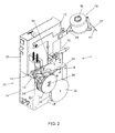
- Fig. 2 shows in perspective view an apparatus 1.
- the apparatus comprises a housing 23 with a wider lower part 24 and a narrower upper part 25, such that a platform 26 is formed at the top of the lower part 24, next to the upper part 25.
- the guide surface 11 has been partly removed, as well as some protective plating.
- the platform 26 can be used as or support a guide surface 11.
- the wheels 9, 10, 14 are at levels to one side of the platform 26, here above the platform 26, whereas at levels to the opposite side of the platform 26, here below, there are two drive wheels 27, 28, driven by a motor 29 (shown in fig. 4 ).
- a first drive wheel 27 can be, when no bag 4 is provided, close to or in engagement with the first wheel 9, whereas a second 28 of the drive wheels can be, when no bag 4 is provided, close to or in engagement with the second wheel 10.
- the drive wheels 27, 28 can be positioned on a common axis 30 and can be driven at a constant speed, for periods of time defined by a control 31 connected to for example a sensor 32 sensing presence of a bag 4 and activating the motor 29 for a period of time necessary for feeding the bag 4 passed the star wheel, as will be discussed hereafter.
- the drive wheels 27, 28 are spaced apart seen in the length direction of the axis 30, such that between the drive wheels space is created for the star wheel 8 and a knife construction 33 to be discussed.
- the drive wheels 27, 28 and/or the snare or band 15, the first and/or the second wheel 9, 10 can have a friction surface for engagement with the bags 4.
- FIG. 3 an apparatus according to fig. 2 is shown, in which the drive wheels 27, 28 have been removed. This shows the star wheel 8, partly, part of the knife construction 33 and a guide block 36 for a foil strip 34 to be dispensed during use from a foil dispense roll 35. Also visible in fig. 3 is a rotating element 37, which is normally connected to the second drive wheel 28, such that it rotates with the second drive wheel 28 around the same axis 30.
- the rotating element 37 is in this embodiment a ring comprising a profile 38, such as a circular outer surface 39 with a lip 40 extending radially outward, between two notches 41 extending radially inward.
- the star wheel 8 is provided with a number of elements 42 extending from a side surface 43 of the star wheel 8, each element 42 positioned between two adjacent cells 12.
- the lip 40 of the rotating element extends during rotation of the ring 37 around the axis 30 in a path extending along the star wheel 8, such that when the ring 37 is rotated at least one of the elements 42 of the star wheel 8 is, as a coupling element, engaged by the extending lip 40 for rotating the star wheel 8 around an axis 44.
- a rotation direction R r of the ring 37 clockwise, in fig.
- a position is shown in which the lip 40 has engaged the element 42A in front of a first cell 12A and is halfway a rotation angle ⁇ imposed by the ring 37 on the star wheel 8.
- ⁇ imposed by the ring 37 on the star wheel 8.
- the construction can be designed such that upon rotation of the rotating element 37 over a first angle ⁇ the star wheel can be rotated over a second angle ⁇ , in opposite direction, to be chosen as desired.
- the ring 37 is part of the transport means or can at least be coupled to the transport means.
- the star wheel 8 has six cells 12 and six coupling elements 42, which can for example be pins, bolts, integrally formed protrusions or other means for engagement.
- the diameters D 1 and D 2 of the ring 37 and the star wheel 8 and the position of the elements 42 and the length of the lip 40 extending from the ring 37 are designed such that upon rotation of the rotating element 37 such that the lip is brought from one side of the star wheel to the opposite side, the star wheel is rotated over an angle ⁇ of 120 degrees. During use this will mean that upon one full rotation of the ring over 360 degrees, the star wheel 8 will be rotated over 120 degrees, meaning two cells.
- the coupling element 42 engaged by the lip 40 will during rotation enter into and subsequently move out of the notch 41 in front of the lip 40, seen in the direction of movement, whereas the trailing coupling element 42 will move into and out of the trailing notch 41, thus allowing the rotation over the angle ⁇ .
- the knife construction 33 comprises a hammer block 45 mounted on an axis 46.
- the block 45 comprises a first arm 47 extending above a cylindrical wall 51 around the axis 30, carrying a knife 48 that extends from the free end of the first arm 47 upward.
- a second arm 49 is provided extending downward from the axis 46 and carrying a follower 50 extending substantially parallel to the first arm 47.
- an opening 52 is provided, positioned at an angle ⁇ relative to the lip 40.
- This can in an embodiment as shown in fig. 11 be a cell 12B following a cell 12C in which a neck 5 of a bag 4 has been gathered and sealed by a seal 53 formed by tape or tape and foil, as will be discussed hereafter. Tape and/or foil, extending as a trailing part over said following cell 12B will then be cut by the knife 48, releasing the sealed bag 5, in fig 1 shown at the right hand side.
- the angle ⁇ shall in this embodiment be chosen such that the star wheel 8 is driven over half the angle ⁇ before the knife 48 is forced into the empty following cell 12B. In that position the cell 12A in fig.
- the knife block 45 can be rotated by gravity and engagement of the follower 50 with the cylindrical wall 51.
- the knife 48 can be moved up by a profile on the cylindrical wall 51, in stead of the opening 50, in which case the follower could be removed.
- the knife 48 could be moved by a separate drive mechanism, such as an individual motor, rod mechanisms, drive belt or any other solution readily available to the person skilled in the art.
- a pin 54 can be mounted on an end of the axis 46, engaging a toothed wheel 55.
- the wheel 55 is designed such that each time the knife 48 has to be moved up the pin 54 is moved over a tooth of the wheel 55, thus forcing the axis 46 to rotate back and forth, forcing the knife 48 into and out off the relevant cell 12 for cutting the tape and/or foil.
- the wheel 55 will rotate at a slower speed than the drive wheels 27, 28 and can be coupled to the same motor 31, for example by a gear mechanism (not shown).
- a roll 56 of tape 57 can be mounted on an arm 58 extending from the housing 13. This is preferably adhesive tape 57 with an adhesive layer 61 facing inward to a core 59 of the roll 56. During use the tape 57 is fed from the roll 56 over a guide mechanism 70 towards the star wheel 8.
- a guide roller 60 is shown over which the tape 57 is guided.
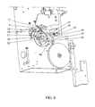
- Fig. 7 shows the relevant part from a first side, substantially corresponding with the view of fig. 2 and 3
- fig. 8 shows the opposite side.
- fig. 8 schematically the tape 57 and the foil strip 34 are shown, feeding towards the star wheel 8.
- the foil dispense roll 35 is positioned such that the foil strip 34 is led in between the first and second drive wheel 27, 28 and along the guide surface 11 under the star wheel in fig. 1 .
- the tape 57 is fed over the guide roller 60 and the star wheel 8.
- Fig. 10A - D schematically show in four steps applying a seal 53 around the neck 5 of a bag 4 or such flexible container.
- the container has to be flexible enough for part thereof, such as a neck, to be gathered in a cell 12 of the star wheel 8.
- the star wheel 8 is shown in a first position, stationary with a cell 12 open to the feeding means 2, for feeding a neck 5 into the cell.
- the neck is gathered into a substantially closed bundled up position by the gathering means as discussed before.
- the neck 5 is grabbed between the first wheel 9 and the first drive wheel 27 and between the second wheel 10 or band 15 and the second drive wheel 28 and pushed towards the cell 12 C.
- Adhesive tape 57 is led over the outer circumference of part of the star wheel 8, with the adhesive layer 61 facing outward, such that it extends at least over the opening 61 of the cell 12C.
- a foils strip 34 for example a paper strip is led from a lower side to the star wheel 8 and is attached to a forward end 62 of the adhesive tape 57.
- the gathered neck 5 has been fed into the cell 12C, forcing the tape 57 into the cell, substantially against the inner wall 63 thereof, the star wheel still in the same position. It can be held in this position by the rotating element, as discussed before. The neck 5 is thus almost entirely surrounded by the adhesive tape 57.
- the star wheel is shown in a position in which it has been rotated counter clockwise over about 60 degrees, for example by engagement of the star wheel 8 by the rotating element or ring 37.
- the tape 57 can have been pulled further around the neck 5, for example but not necessarily to such extend that it is attached to itself, forming a joint 65, fully circumventing the neck 5.
- the foil strip 34 has been drawn off the roll 35 further and has been attached to the tape 57 over such length that it traverses the joint 65.
- a position is shown in which the star wheel 8 has been rotated further, counter clockwise, over for example substantially another 60 degrees, such that the opening 61 of the cell 12C extends above the guide surface 11 or at least to such extend that the bag 4 can be discharged from the cell 12A.
- the knife 48 can, for example as discussed before, be driven upward, into the cell 12B, cutting through the combined tape 57 and strip 34, cutting the seal 53 off from the tape 57 and foil 34.
- the adjacent cell 12A has become available for feeding a further neck 5 into it.
- the foil strip can be made of paper or plastic or another material. Preferably it can easily be torn by a user, preferably easier than the tape 57, such that the seal 53 can be broken easily. In an alternative embodiment the foil strip could be left out, the seal formed by tape only. In still another embodiment the foil strip could be replaced by a strip of individual elements to be adhered to the tape 57 at one or opposite sides of the joint 65, such that the ends of the tape on opposite sides of said joint will not adhere to each other. These individual elements can for example be carried on a strip like backing.
- a substantially non adhesive tape can be used, which is provided with adhesive only in the parts that have to enclose the neck 5 of a bag 4, but not the parts that form the free ends of the seal, distanced over a certain distance from the joint.
- the adhesive can for example be applied to the non adhesive tape in blocks prior to delivery or near or at the star wheel, before feeding the neck into the cell 12.
- a control 31 is shown, for example connected to a sensor 32 for sensing a bag in a desired proximity of the star wheel 8, such that the gathering can be advanced and the rotating element should be rotated.
- the control can also be provided with a communication means 67 and/or positioning means 68, such as but not limited to wireless communication means and/or wired communication means, such as a telephone, GPS or GPRS.
- the communication means 67 can be designed to communicate with for example a computer of telephone network, with a supplier of tape and/or foil, with a maintenance firm or the like.
- Further sensors can be connected to the control, such as one or more sensors for sensing the amount of tape 57 and/or foil 34 strip dispensed and/or used and/or sensing a remaining amount of tape 57 and/or strip 34 remaining on the respective rolls 35, 56.
- the rolls 35 and/or 56 can be provided with indicators, such as but not limited to RFID chips, bar codes or other means that can be physically or electronically read by sensors in the apparatus, for identification of the rolls and setting a mode of the apparatus through the control 31, for example the length of tape to be dispensed, tension of the strip 34 and/or tape 57 to be applied, or even bringing the apparatus in a working or non working mode.
- the positioning means 68 can be provided for sensing and communicating location and/or location changes of the apparatus 1, such that it is easy to keep track of the apparatus.
- Counting means can be provided for counting the number of seals manufactured with the apparatus, for example by counting the number of revolutions of the star wheel 8 and/or of one of the drive wheels and/or of the rotating element 37.
- the orientation of the apparatus can be different, such that for example the bags are fed through the apparatus vertically, for example hanging from transport means or carried on transport means with the necks upward, wherein the axis 44 of the star wheel can include an angle with a horizontal directed, can be inclined or disposed vertically.
- the rotating element 37 and especially the lip 40 can be positioned such that it engages the star wheel 8 at a side spaced apart from the area where the neck is gathered an fed into a cell, for example in fig. 10 on the upper side of the star wheel 8 or at least at a side of the star wheel opposite the guide surface 11.
- the star wheel can also be driven differently, for example through a step motor engaging the axis 44 or by the feeding and/or discharging means, the ring 37 only used for blocking and allowing rotation of the star wheel 8 over a specific angle.
- a star wheel can be in the form of an endless star belt, formed as a belt having a series of cells in an outwardly facing surface, guided over at least two end wheels, such that a series of cells 12 is fed along the guide surface, allowing a series of bags to be handled at the same time.
- the position of the tape roll 56 and the foil strip roll 35 can be changed, for example changed over.
- Means can be provided to print information on and/or in the tape and/or the foil strip, such as sealing date, expiration date of the product P, packing apparatus identification, advertisements or other information.
- the width of the strip of foil 34 is about the same as the width of the tape 57. These widths can be different, for example when the foil strip 34 should have a greater with in order to provide further information, such as user information, warranties and other communications.
Landscapes
- Engineering & Computer Science (AREA)
- Mechanical Engineering (AREA)
- Auxiliary Devices For And Details Of Packaging Control (AREA)
- Package Closures (AREA)
Claims (15)
- Vorrichtung (1) zum Verschließen flexibler Beutel (4), umfassend eine Aufnahmegruppe (7) für einen Hals des Beutels (4), die mindestens ein Transportmittel (2, 3) und mindestens einen Bandspender (35, 56) aufweist, wobei die Aufnahmegruppe (7) ein Sternrad (8) umfasst und der Bandspender (35, 56) eine Führung umfasst, um Band von dem Bandspender 835, 56) über einen Teil des Sternrads (8) zu leiten, wobei die Transportmittel (2, 3) in oder entlang von mindestens einer Zelle (12) des Sternrads (8) verlaufen, wobei das Sternrad (8) intermittierend angetrieben wird, dadurch gekennzeichnet, dass das Sternrad (8) so an die Transportmittel (2, 3) gekoppelt ist, dass, wenn die Transportmittel angetrieben werden, um den Hals (5) aufzunehmen und den Hals (5) des Beutels (4) in eine Zelle (12) des Sternrads (8) zu transportieren, das Sternrad (8) ortsfest bleibt.
- Vorrichtung nach Anspruch 1, wobei die Transportmittel (2, 3) zwei Sets von Transportelementen wie beispielsweise Räder und/oder Transportbänder umfassen, die im Wesentlichen parallel zueinander in einem Abstand voneinander sind, wobei das Sternrad (8) mindestens teilweise zwischen den zwei Sets verläuft.
- Vorrichtung nach Anspruch 1 oder 2, wobei die Transportmittel (2, 3) ein Drehelement (38) umfassen oder mit diesem gekoppelt sind, das mindestens ein Verlängerungselement (40) umfasst, wobei sich das Element (38) bei Verwendung in einer Bahn bewegt, die durch eine und entlang einer Seite des Sternrads (8) verläuft, sodass, wenn das Drehelement (38) über einen ersten Winkel gedreht wird, das Verlängerungselement (40) in das Sternrad (8) eingreift, um das Sternrad (8) über einen zweiten Winkel zu drehen.
- Vorrichtung nach Anspruch 3, wobei das Sternrad (8) mit mindestens einem Kopplungselement (42) versehen ist, das in das Drehelement (38) eingreift, das Drehelement (38) mit mindestens einem Profil (41) wie beispielsweise einer Öffnung oder einer Kerbe versehen ist, in der oder auf der sich das Kopplungselement (42) beim Drehen des Drehelements (38) bewegen kann, sodass das Sternrad (8) über den zweiten Winkel gedreht wird, bevor das Kopplungselement (42) freigegeben wird.
- Vorrichtung nach Anspruch 3 oder 4, wobei das Sternrad (8) eine Anzahl von Zellen (12) aufweist, wobei die Transportmittel (2, 3) so konzipiert sind, dass bei einem ersten Winkel von 360 Grad der zweite Winkel so ist, dass das Sternrad (8) über einen zweiten Winkel, definiert von einer diskreten Anzahl von Zellen (12), vorzugsweise zwei oder drei Zellen, gedreht wird.
- Vorrichtung nach einem der Ansprüche 1-5, wobei ein Näherungssensor (32) nahe der Transportmittel (2, 3) und/oder der Aufnahmemittel (7) bereitgestellt ist.
- Vorrichtung nach einem der Ansprüche 1-6, wobei Mittel bereitgestellt sind, um einen Folienstreifen an einem Teil des Sternrads (8) entlang zu führen und/oder eine Führungsfläche am Sternrad (8) entlang verläuft, zum Eingreifen mit einem Band, das über das Sternrad (8) geleitet wird.
- Vorrichtung nach einem der vorhergehenden Ansprüche, wobei eine Kommunikationsvorrichtung (67) für die Kommunikation, vorzugsweise eine drahtlose Kommunikation, zwischen der Vorrichtung und einer Steuervorrichtung bereitgestellt ist.
- Vorrichtung nach einem der Ansprüche 1-8, wobei eine Positioniervorrichtung (68) zum Abtasten und Kommunizieren des Standorts und/oder einer Änderung des Standorts der Vorrichtung bereitgestellt ist.
- Vorrichtung nach einem der vorhergehenden Ansprüche, wobei ferner eine Steuervorrichtung (31) bereitgestellt ist, die mit mindestens einem Sensor verbunden ist, um die Anwesenheit des Bands und/oder der Folie zu detektieren.
- Verfahren zum Versiegeln flexibler Behälter (4), umfassend folgende Schritte:- Leiten eines Streifens von Klebeband entlang eines Teils eines Sternrads (8), sodass das Band über eine Öffnung von mindestens einer Zelle (12) des Sternrads (8) läuft;- Aufnehmen von Halsmaterial eines Behälters (4) durch Einführen des Halsmaterials in die Zelle (12) des Sternrads (8) in einer ersten Richtung;- Drehen des Sternrads (8) über einen Winkel, so dass das aufgenommene Halsmaterial, gebunden in einen geschlossenen Zustand durch mindestens das Band, aus der Zelle (12) in einer zweiten Richtung bewegt wird;- Befestigen eines Folienstreifens an einem Teil des Bandes; und- während oder nach dem Drehen des Sternrads (8), Einführen und/oder Halten des Bandes über eine Öffnung einer nächsten Zelle (12) des Sternrads (8), gekennzeichnet durch den Schritt, dass das Sternrad (8) während des Aufnehmens und Einführens des Halses (6) in die Zelle (12) ortsfest bleibt, sodass das Band gegen die Innenwand der Zelle (12) und um das aufgenommene Halsmaterial forciert wird.
- Verfahren nach Anspruch 11, wobei das Aufnehmen unter Verwendung von mindestens einem von einem Antriebsmechanismus angetriebenen Aufnahmerad oder -band erfolgt, wobei ein Drehelement bereitgestellt ist, das an den Antriebsmechanismus und/oder die Aufnahmemittel gekoppelt ist, wobei das Drehelement gedreht wird, um zum Eingreifen in das oder Ausgreifen aus dem Sternrad oder einem damit verbundenen Element gebracht zu werden, um das Sternrad intermittierend über einen Winkel zu bewegen.
- Verfahren nach Anspruch 12, wobei das Sternrad in der ortsfesten Position durch das Drehelement während eines Teils einer Drehung des Drehelements gehalten wird.
- Verfahren nach einem der Ansprüche 11-13, wobei Behälterhälse in einer im Wesentlichen flachen Position in die Aufnahmemittel eingeführt werden.
- Verfahren nach einem der Ansprüche 11-14, wobei ein Behälterhals, der sich den Aufnahmemitteln nähert, detektiert wird, woraufhin das Aufnehmen des Behälterhalses beginnt und ein Drehelement zum Drehen des Sternrads über den Winkel in einer Drehrichtung angetrieben wird.
Applications Claiming Priority (1)
| Application Number | Priority Date | Filing Date | Title |
|---|---|---|---|
| NL2002595A NL2002595C2 (en) | 2009-03-05 | 2009-03-05 | Apparatus and method for sealing bags. |
Publications (2)
| Publication Number | Publication Date |
|---|---|
| EP2226255A1 EP2226255A1 (de) | 2010-09-08 |
| EP2226255B1 true EP2226255B1 (de) | 2013-08-14 |
Family
ID=41168698
Family Applications (1)
| Application Number | Title | Priority Date | Filing Date |
|---|---|---|---|
| EP10155579.5A Active EP2226255B1 (de) | 2009-03-05 | 2010-03-05 | Vorrichtung und Verfahren zum Verschliessen von Beuteln |
Country Status (3)
| Country | Link |
|---|---|
| US (1) | US20100223888A1 (de) |
| EP (1) | EP2226255B1 (de) |
| NL (1) | NL2002595C2 (de) |
Families Citing this family (6)
| Publication number | Priority date | Publication date | Assignee | Title |
|---|---|---|---|---|
| DK2794405T3 (en) | 2011-12-20 | 2017-02-20 | Burford Corp | DIGITAL CODE TAPE CLOSER |
| US11472579B2 (en) * | 2018-12-04 | 2022-10-18 | Gpcp Ip Holdings Llc | Film securing apparatus and method |
| US12077337B2 (en) * | 2018-12-04 | 2024-09-03 | Yum Connect, LLC | Systems and methods for sealing a container |
| CA3209605A1 (en) | 2021-02-24 | 2022-09-01 | Yum Connect, LLC | Automated beverage dispenser system and method |
| US12338022B2 (en) | 2023-02-10 | 2025-06-24 | Yum Connect, LLC | Automated beverage dispenser system and method |
| US12415716B2 (en) | 2023-04-25 | 2025-09-16 | Yum Connect, LLC | Automated beverage dispenser system and method |
Family Cites Families (16)
| Publication number | Priority date | Publication date | Assignee | Title |
|---|---|---|---|---|
| US2916863A (en) * | 1954-12-09 | 1959-12-15 | Charles R Leighton | Bag tying machine |
| US2841935A (en) * | 1956-03-12 | 1958-07-08 | Derby Sealers Inc | Bag-tying machine |
| US3729896A (en) * | 1971-07-19 | 1973-05-01 | A Lehmann | Device for tying the ends of bags |
| US3783585A (en) * | 1972-09-18 | 1974-01-08 | Thurme Eng Co Ltd | Machine for closing filled bags |
| US3922834A (en) * | 1974-04-03 | 1975-12-02 | Norpak Machines Limited | Apparatus for closing of wrapping bags or sleeves |
| DE2419072A1 (de) * | 1974-04-20 | 1975-11-06 | Norpak Machines Ltd | Verfahren und vorrichtung zum schliessen von beuteln |
| US4398379A (en) * | 1981-03-11 | 1983-08-16 | Burford Charles E | Tab attachment device |
| JPS58149228A (ja) * | 1982-02-19 | 1983-09-05 | 株式会社大生機械 | 包装用結束装置 |
| DE3377055D1 (en) * | 1982-07-20 | 1988-07-21 | Thurne Eng Co Ltd | Bag tying machine |
| NL8500050A (nl) * | 1985-01-09 | 1986-08-01 | Nicolaas Van Rosendal | Inrichting voor het aanbrengen van een sluitstrip, en een cassette daarvoor. |
| JPH0350984Y2 (de) * | 1986-05-13 | 1991-10-31 | ||
| US4721545A (en) * | 1986-09-02 | 1988-01-26 | Christos Santorineos | Balloon sealer |
| DE8808394U1 (de) * | 1988-06-30 | 1988-09-01 | Affeldt Verpackungsmaschinen GmbH, 2200 Neuendorf | Vorrichtung zum automatischen Verschließen von Beuteln mittels Klebebändern |
| NL9202118A (nl) * | 1992-12-07 | 1994-07-01 | Novem Trading Int Bv | Inrichting voor het aanbrengen van een sluitstrip. |
| IT1281206B1 (it) * | 1995-02-15 | 1998-02-17 | Sasib Spa | Dispositivo trasportatore su percorsi circolari, in particolare per gruppi di oggetti astiformi delicati e nelle macchine impacchettatrici |
| NL1013103C1 (nl) * | 1999-09-21 | 2001-03-22 | Innoseal Systems Internat B V | Zakkensluitinrichting. |
-
2009
- 2009-03-05 NL NL2002595A patent/NL2002595C2/en not_active IP Right Cessation
-
2010
- 2010-03-05 EP EP10155579.5A patent/EP2226255B1/de active Active
- 2010-03-05 US US12/718,637 patent/US20100223888A1/en not_active Abandoned
Also Published As
| Publication number | Publication date |
|---|---|
| US20100223888A1 (en) | 2010-09-09 |
| EP2226255A1 (de) | 2010-09-08 |
| NL2002595C2 (en) | 2010-09-07 |
Similar Documents
| Publication | Publication Date | Title |
|---|---|---|
| EP2226255B1 (de) | Vorrichtung und Verfahren zum Verschliessen von Beuteln | |
| EP3292048B1 (de) | Verpackungssystem | |
| CN102227352B (zh) | 用于制造束条包装的方法和装置以及束条包装 | |
| US5771664A (en) | Label for bags with wire loop closures | |
| CA2182006C (en) | Automated method and apparatus for detachably securing flexible packages to a display strip | |
| US8573396B2 (en) | Marking packages | |
| US20090056872A1 (en) | Labeling apparatus for applying wrap labels and method | |
| US6041575A (en) | Method and apparatus for applying article to interior surface of flexible package | |
| EP2334477B1 (de) | Verpackungsverfahren und -vorrichtung | |
| EP2635495B1 (de) | Vorrichtung und verfahren zum verbinden oder umbinden von produkten | |
| NL2005627C2 (en) | Apparatus and method for sealing or tying products. | |
| US5336359A (en) | System for applying literature to a wall of an object | |
| CH669767A5 (de) | ||
| WO2018085471A2 (en) | Packaging system | |
| EP3142932B1 (de) | Vorrichtung und verfahren zum umschliessen oder umbinden von produkten | |
| US20190106230A1 (en) | Machine for packaging piece good combinations with additional decorating device | |
| JP5572025B2 (ja) | Ptpシート製造装置 | |
| EP3986795B1 (de) | System zum halbautomatischen schliessen von flexiblen behältern | |
| EP3119681B1 (de) | System zur positionierung eines etikeiits auf einer verpackung | |
| JP2894684B1 (ja) | サンドイッチの包装方法及びその包装装置 | |
| KR20140115650A (ko) | 약제포장장치의 포장모듈 | |
| GB2449621A (en) | Labelling plant |
Legal Events
| Date | Code | Title | Description |
|---|---|---|---|
| PUAI | Public reference made under article 153(3) epc to a published international application that has entered the european phase |
Free format text: ORIGINAL CODE: 0009012 |
|
| AK | Designated contracting states |
Kind code of ref document: A1 Designated state(s): AT BE BG CH CY CZ DE DK EE ES FI FR GB GR HR HU IE IS IT LI LT LU LV MC MK MT NL NO PL PT RO SE SI SK SM TR |
|
| AX | Request for extension of the european patent |
Extension state: AL BA ME RS |
|
| 17P | Request for examination filed |
Effective date: 20110223 |
|
| 17Q | First examination report despatched |
Effective date: 20110701 |
|
| REG | Reference to a national code |
Ref country code: DE Ref legal event code: R079 Ref document number: 602010009313 Country of ref document: DE Free format text: PREVIOUS MAIN CLASS: B65B0051060000 Ipc: B65B0007020000 |
|
| GRAP | Despatch of communication of intention to grant a patent |
Free format text: ORIGINAL CODE: EPIDOSNIGR1 |
|
| RIC1 | Information provided on ipc code assigned before grant |
Ipc: B65B 65/04 20060101ALI20130220BHEP Ipc: B65B 7/02 20060101AFI20130220BHEP Ipc: B65B 51/06 20060101ALI20130220BHEP |
|
| GRAS | Grant fee paid |
Free format text: ORIGINAL CODE: EPIDOSNIGR3 |
|
| GRAA | (expected) grant |
Free format text: ORIGINAL CODE: 0009210 |
|
| AK | Designated contracting states |
Kind code of ref document: B1 Designated state(s): AT BE BG CH CY CZ DE DK EE ES FI FR GB GR HR HU IE IS IT LI LT LU LV MC MK MT NL NO PL PT RO SE SI SK SM TR |
|
| REG | Reference to a national code |
Ref country code: GB Ref legal event code: FG4D |
|
| REG | Reference to a national code |
Ref country code: CH Ref legal event code: EP Ref country code: AT Ref legal event code: REF Ref document number: 626658 Country of ref document: AT Kind code of ref document: T Effective date: 20130815 |
|
| REG | Reference to a national code |
Ref country code: IE Ref legal event code: FG4D |
|
| REG | Reference to a national code |
Ref country code: DE Ref legal event code: R096 Ref document number: 602010009313 Country of ref document: DE Effective date: 20131017 |
|
| REG | Reference to a national code |
Ref country code: NL Ref legal event code: T3 |
|
| REG | Reference to a national code |
Ref country code: AT Ref legal event code: MK05 Ref document number: 626658 Country of ref document: AT Kind code of ref document: T Effective date: 20130814 |
|
| REG | Reference to a national code |
Ref country code: LT Ref legal event code: MG4D |
|
| PG25 | Lapsed in a contracting state [announced via postgrant information from national office to epo] |
Ref country code: LT Free format text: LAPSE BECAUSE OF FAILURE TO SUBMIT A TRANSLATION OF THE DESCRIPTION OR TO PAY THE FEE WITHIN THE PRESCRIBED TIME-LIMIT Effective date: 20130814 Ref country code: AT Free format text: LAPSE BECAUSE OF FAILURE TO SUBMIT A TRANSLATION OF THE DESCRIPTION OR TO PAY THE FEE WITHIN THE PRESCRIBED TIME-LIMIT Effective date: 20130814 Ref country code: IS Free format text: LAPSE BECAUSE OF FAILURE TO SUBMIT A TRANSLATION OF THE DESCRIPTION OR TO PAY THE FEE WITHIN THE PRESCRIBED TIME-LIMIT Effective date: 20131214 Ref country code: HR Free format text: LAPSE BECAUSE OF FAILURE TO SUBMIT A TRANSLATION OF THE DESCRIPTION OR TO PAY THE FEE WITHIN THE PRESCRIBED TIME-LIMIT Effective date: 20130814 Ref country code: PT Free format text: LAPSE BECAUSE OF FAILURE TO SUBMIT A TRANSLATION OF THE DESCRIPTION OR TO PAY THE FEE WITHIN THE PRESCRIBED TIME-LIMIT Effective date: 20131216 Ref country code: NO Free format text: LAPSE BECAUSE OF FAILURE TO SUBMIT A TRANSLATION OF THE DESCRIPTION OR TO PAY THE FEE WITHIN THE PRESCRIBED TIME-LIMIT Effective date: 20131114 Ref country code: CY Free format text: LAPSE BECAUSE OF FAILURE TO SUBMIT A TRANSLATION OF THE DESCRIPTION OR TO PAY THE FEE WITHIN THE PRESCRIBED TIME-LIMIT Effective date: 20130904 Ref country code: SE Free format text: LAPSE BECAUSE OF FAILURE TO SUBMIT A TRANSLATION OF THE DESCRIPTION OR TO PAY THE FEE WITHIN THE PRESCRIBED TIME-LIMIT Effective date: 20130814 |
|
| PG25 | Lapsed in a contracting state [announced via postgrant information from national office to epo] |
Ref country code: FI Free format text: LAPSE BECAUSE OF FAILURE TO SUBMIT A TRANSLATION OF THE DESCRIPTION OR TO PAY THE FEE WITHIN THE PRESCRIBED TIME-LIMIT Effective date: 20130814 Ref country code: BE Free format text: LAPSE BECAUSE OF FAILURE TO SUBMIT A TRANSLATION OF THE DESCRIPTION OR TO PAY THE FEE WITHIN THE PRESCRIBED TIME-LIMIT Effective date: 20130814 Ref country code: PL Free format text: LAPSE BECAUSE OF FAILURE TO SUBMIT A TRANSLATION OF THE DESCRIPTION OR TO PAY THE FEE WITHIN THE PRESCRIBED TIME-LIMIT Effective date: 20130814 Ref country code: SI Free format text: LAPSE BECAUSE OF FAILURE TO SUBMIT A TRANSLATION OF THE DESCRIPTION OR TO PAY THE FEE WITHIN THE PRESCRIBED TIME-LIMIT Effective date: 20130814 Ref country code: GR Free format text: LAPSE BECAUSE OF FAILURE TO SUBMIT A TRANSLATION OF THE DESCRIPTION OR TO PAY THE FEE WITHIN THE PRESCRIBED TIME-LIMIT Effective date: 20131115 Ref country code: LV Free format text: LAPSE BECAUSE OF FAILURE TO SUBMIT A TRANSLATION OF THE DESCRIPTION OR TO PAY THE FEE WITHIN THE PRESCRIBED TIME-LIMIT Effective date: 20130814 |
|
| PG25 | Lapsed in a contracting state [announced via postgrant information from national office to epo] |
Ref country code: CY Free format text: LAPSE BECAUSE OF FAILURE TO SUBMIT A TRANSLATION OF THE DESCRIPTION OR TO PAY THE FEE WITHIN THE PRESCRIBED TIME-LIMIT Effective date: 20130814 |
|
| PG25 | Lapsed in a contracting state [announced via postgrant information from national office to epo] |
Ref country code: DK Free format text: LAPSE BECAUSE OF FAILURE TO SUBMIT A TRANSLATION OF THE DESCRIPTION OR TO PAY THE FEE WITHIN THE PRESCRIBED TIME-LIMIT Effective date: 20130814 Ref country code: EE Free format text: LAPSE BECAUSE OF FAILURE TO SUBMIT A TRANSLATION OF THE DESCRIPTION OR TO PAY THE FEE WITHIN THE PRESCRIBED TIME-LIMIT Effective date: 20130814 Ref country code: CZ Free format text: LAPSE BECAUSE OF FAILURE TO SUBMIT A TRANSLATION OF THE DESCRIPTION OR TO PAY THE FEE WITHIN THE PRESCRIBED TIME-LIMIT Effective date: 20130814 Ref country code: RO Free format text: LAPSE BECAUSE OF FAILURE TO SUBMIT A TRANSLATION OF THE DESCRIPTION OR TO PAY THE FEE WITHIN THE PRESCRIBED TIME-LIMIT Effective date: 20130814 Ref country code: SK Free format text: LAPSE BECAUSE OF FAILURE TO SUBMIT A TRANSLATION OF THE DESCRIPTION OR TO PAY THE FEE WITHIN THE PRESCRIBED TIME-LIMIT Effective date: 20130814 |
|
| PG25 | Lapsed in a contracting state [announced via postgrant information from national office to epo] |
Ref country code: ES Free format text: LAPSE BECAUSE OF FAILURE TO SUBMIT A TRANSLATION OF THE DESCRIPTION OR TO PAY THE FEE WITHIN THE PRESCRIBED TIME-LIMIT Effective date: 20130814 Ref country code: IT Free format text: LAPSE BECAUSE OF FAILURE TO SUBMIT A TRANSLATION OF THE DESCRIPTION OR TO PAY THE FEE WITHIN THE PRESCRIBED TIME-LIMIT Effective date: 20130814 |
|
| PLBE | No opposition filed within time limit |
Free format text: ORIGINAL CODE: 0009261 |
|
| STAA | Information on the status of an ep patent application or granted ep patent |
Free format text: STATUS: NO OPPOSITION FILED WITHIN TIME LIMIT |
|
| 26N | No opposition filed |
Effective date: 20140515 |
|
| REG | Reference to a national code |
Ref country code: DE Ref legal event code: R097 Ref document number: 602010009313 Country of ref document: DE Effective date: 20140515 |
|
| REG | Reference to a national code |
Ref country code: DE Ref legal event code: R119 Ref document number: 602010009313 Country of ref document: DE |
|
| PG25 | Lapsed in a contracting state [announced via postgrant information from national office to epo] |
Ref country code: LU Free format text: LAPSE BECAUSE OF FAILURE TO SUBMIT A TRANSLATION OF THE DESCRIPTION OR TO PAY THE FEE WITHIN THE PRESCRIBED TIME-LIMIT Effective date: 20140305 |
|
| REG | Reference to a national code |
Ref country code: CH Ref legal event code: PL |
|
| GBPC | Gb: european patent ceased through non-payment of renewal fee |
Effective date: 20140305 |
|
| REG | Reference to a national code |
Ref country code: FR Ref legal event code: ST Effective date: 20141128 |
|
| REG | Reference to a national code |
Ref country code: IE Ref legal event code: MM4A |
|
| REG | Reference to a national code |
Ref country code: DE Ref legal event code: R119 Ref document number: 602010009313 Country of ref document: DE Effective date: 20141001 |
|
| PG25 | Lapsed in a contracting state [announced via postgrant information from national office to epo] |
Ref country code: FR Free format text: LAPSE BECAUSE OF NON-PAYMENT OF DUE FEES Effective date: 20140331 Ref country code: LI Free format text: LAPSE BECAUSE OF NON-PAYMENT OF DUE FEES Effective date: 20140331 Ref country code: DE Free format text: LAPSE BECAUSE OF NON-PAYMENT OF DUE FEES Effective date: 20141001 Ref country code: GB Free format text: LAPSE BECAUSE OF NON-PAYMENT OF DUE FEES Effective date: 20140305 Ref country code: IE Free format text: LAPSE BECAUSE OF NON-PAYMENT OF DUE FEES Effective date: 20140305 Ref country code: CH Free format text: LAPSE BECAUSE OF NON-PAYMENT OF DUE FEES Effective date: 20140331 |
|
| PG25 | Lapsed in a contracting state [announced via postgrant information from national office to epo] |
Ref country code: MT Free format text: LAPSE BECAUSE OF FAILURE TO SUBMIT A TRANSLATION OF THE DESCRIPTION OR TO PAY THE FEE WITHIN THE PRESCRIBED TIME-LIMIT Effective date: 20130814 |
|
| PG25 | Lapsed in a contracting state [announced via postgrant information from national office to epo] |
Ref country code: SM Free format text: LAPSE BECAUSE OF FAILURE TO SUBMIT A TRANSLATION OF THE DESCRIPTION OR TO PAY THE FEE WITHIN THE PRESCRIBED TIME-LIMIT Effective date: 20130814 |
|
| PG25 | Lapsed in a contracting state [announced via postgrant information from national office to epo] |
Ref country code: MC Free format text: LAPSE BECAUSE OF FAILURE TO SUBMIT A TRANSLATION OF THE DESCRIPTION OR TO PAY THE FEE WITHIN THE PRESCRIBED TIME-LIMIT Effective date: 20130814 |
|
| PG25 | Lapsed in a contracting state [announced via postgrant information from national office to epo] |
Ref country code: BG Free format text: LAPSE BECAUSE OF FAILURE TO SUBMIT A TRANSLATION OF THE DESCRIPTION OR TO PAY THE FEE WITHIN THE PRESCRIBED TIME-LIMIT Effective date: 20130814 |
|
| PG25 | Lapsed in a contracting state [announced via postgrant information from national office to epo] |
Ref country code: HU Free format text: LAPSE BECAUSE OF FAILURE TO SUBMIT A TRANSLATION OF THE DESCRIPTION OR TO PAY THE FEE WITHIN THE PRESCRIBED TIME-LIMIT; INVALID AB INITIO Effective date: 20100305 Ref country code: TR Free format text: LAPSE BECAUSE OF FAILURE TO SUBMIT A TRANSLATION OF THE DESCRIPTION OR TO PAY THE FEE WITHIN THE PRESCRIBED TIME-LIMIT Effective date: 20130814 |
|
| PG25 | Lapsed in a contracting state [announced via postgrant information from national office to epo] |
Ref country code: MK Free format text: LAPSE BECAUSE OF FAILURE TO SUBMIT A TRANSLATION OF THE DESCRIPTION OR TO PAY THE FEE WITHIN THE PRESCRIBED TIME-LIMIT Effective date: 20130814 |
|
| PGFP | Annual fee paid to national office [announced via postgrant information from national office to epo] |
Ref country code: NL Payment date: 20260319 Year of fee payment: 17 |