EP3986355B1 - Verbesserter massagekopf für massagevorrichtung und massagevorrichtung mit einem solchen kopf - Google Patents
Verbesserter massagekopf für massagevorrichtung und massagevorrichtung mit einem solchen kopf Download PDFInfo
- Publication number
- EP3986355B1 EP3986355B1 EP20731887.4A EP20731887A EP3986355B1 EP 3986355 B1 EP3986355 B1 EP 3986355B1 EP 20731887 A EP20731887 A EP 20731887A EP 3986355 B1 EP3986355 B1 EP 3986355B1
- Authority
- EP
- European Patent Office
- Prior art keywords
- massage
- roller
- rollers
- axis
- massage head
- Prior art date
- Legal status (The legal status is an assumption and is not a legal conclusion. Google has not performed a legal analysis and makes no representation as to the accuracy of the status listed.)
- Active
Links
Images


Classifications
-
- A—HUMAN NECESSITIES
- A61—MEDICAL OR VETERINARY SCIENCE; HYGIENE
- A61H—PHYSICAL THERAPY APPARATUS, e.g. DEVICES FOR LOCATING OR STIMULATING REFLEX POINTS IN THE BODY; ARTIFICIAL RESPIRATION; MASSAGE; BATHING DEVICES FOR SPECIAL THERAPEUTIC OR HYGIENIC PURPOSES OR SPECIFIC PARTS OF THE BODY
- A61H15/00—Massage by means of rollers, balls, e.g. inflatable, chains, or roller chains
- A61H15/0078—Massage by means of rollers, balls, e.g. inflatable, chains, or roller chains power-driven
- A61H15/0085—Massage by means of rollers, balls, e.g. inflatable, chains, or roller chains power-driven hand-held
-
- A—HUMAN NECESSITIES
- A61—MEDICAL OR VETERINARY SCIENCE; HYGIENE
- A61H—PHYSICAL THERAPY APPARATUS, e.g. DEVICES FOR LOCATING OR STIMULATING REFLEX POINTS IN THE BODY; ARTIFICIAL RESPIRATION; MASSAGE; BATHING DEVICES FOR SPECIAL THERAPEUTIC OR HYGIENIC PURPOSES OR SPECIFIC PARTS OF THE BODY
- A61H15/00—Massage by means of rollers, balls, e.g. inflatable, chains, or roller chains
- A61H2015/0007—Massage by means of rollers, balls, e.g. inflatable, chains, or roller chains with balls or rollers rotating about their own axis
- A61H2015/0014—Massage by means of rollers, balls, e.g. inflatable, chains, or roller chains with balls or rollers rotating about their own axis cylinder-like, i.e. rollers
-
- A—HUMAN NECESSITIES
- A61—MEDICAL OR VETERINARY SCIENCE; HYGIENE
- A61H—PHYSICAL THERAPY APPARATUS, e.g. DEVICES FOR LOCATING OR STIMULATING REFLEX POINTS IN THE BODY; ARTIFICIAL RESPIRATION; MASSAGE; BATHING DEVICES FOR SPECIAL THERAPEUTIC OR HYGIENIC PURPOSES OR SPECIFIC PARTS OF THE BODY
- A61H15/00—Massage by means of rollers, balls, e.g. inflatable, chains, or roller chains
- A61H2015/0007—Massage by means of rollers, balls, e.g. inflatable, chains, or roller chains with balls or rollers rotating about their own axis
- A61H2015/0057—Massage by means of rollers, balls, e.g. inflatable, chains, or roller chains with balls or rollers rotating about their own axis the axis being resiliently biased
-
- A—HUMAN NECESSITIES
- A61—MEDICAL OR VETERINARY SCIENCE; HYGIENE
- A61H—PHYSICAL THERAPY APPARATUS, e.g. DEVICES FOR LOCATING OR STIMULATING REFLEX POINTS IN THE BODY; ARTIFICIAL RESPIRATION; MASSAGE; BATHING DEVICES FOR SPECIAL THERAPEUTIC OR HYGIENIC PURPOSES OR SPECIFIC PARTS OF THE BODY
- A61H2201/00—Characteristics of apparatus not provided for in the preceding codes
- A61H2201/01—Constructive details
- A61H2201/0119—Support for the device
- A61H2201/0153—Support for the device hand-held
-
- A—HUMAN NECESSITIES
- A61—MEDICAL OR VETERINARY SCIENCE; HYGIENE
- A61H—PHYSICAL THERAPY APPARATUS, e.g. DEVICES FOR LOCATING OR STIMULATING REFLEX POINTS IN THE BODY; ARTIFICIAL RESPIRATION; MASSAGE; BATHING DEVICES FOR SPECIAL THERAPEUTIC OR HYGIENIC PURPOSES OR SPECIFIC PARTS OF THE BODY
- A61H2201/00—Characteristics of apparatus not provided for in the preceding codes
- A61H2201/01—Constructive details
- A61H2201/0157—Constructive details portable
-
- A—HUMAN NECESSITIES
- A61—MEDICAL OR VETERINARY SCIENCE; HYGIENE
- A61H—PHYSICAL THERAPY APPARATUS, e.g. DEVICES FOR LOCATING OR STIMULATING REFLEX POINTS IN THE BODY; ARTIFICIAL RESPIRATION; MASSAGE; BATHING DEVICES FOR SPECIAL THERAPEUTIC OR HYGIENIC PURPOSES OR SPECIFIC PARTS OF THE BODY
- A61H2201/00—Characteristics of apparatus not provided for in the preceding codes
- A61H2201/12—Driving means
- A61H2201/1207—Driving means with electric or magnetic drive
- A61H2201/1215—Rotary drive
-
- A—HUMAN NECESSITIES
- A61—MEDICAL OR VETERINARY SCIENCE; HYGIENE
- A61H—PHYSICAL THERAPY APPARATUS, e.g. DEVICES FOR LOCATING OR STIMULATING REFLEX POINTS IN THE BODY; ARTIFICIAL RESPIRATION; MASSAGE; BATHING DEVICES FOR SPECIAL THERAPEUTIC OR HYGIENIC PURPOSES OR SPECIFIC PARTS OF THE BODY
- A61H2201/00—Characteristics of apparatus not provided for in the preceding codes
- A61H2201/16—Physical interface with patient
- A61H2201/1602—Physical interface with patient kind of interface, e.g. head rest, knee support or lumbar support
- A61H2201/1635—Hand or arm, e.g. handle
-
- A—HUMAN NECESSITIES
- A61—MEDICAL OR VETERINARY SCIENCE; HYGIENE
- A61H—PHYSICAL THERAPY APPARATUS, e.g. DEVICES FOR LOCATING OR STIMULATING REFLEX POINTS IN THE BODY; ARTIFICIAL RESPIRATION; MASSAGE; BATHING DEVICES FOR SPECIAL THERAPEUTIC OR HYGIENIC PURPOSES OR SPECIFIC PARTS OF THE BODY
- A61H2201/00—Characteristics of apparatus not provided for in the preceding codes
- A61H2201/16—Physical interface with patient
- A61H2201/1657—Movement of interface, i.e. force application means
- A61H2201/1664—Movement of interface, i.e. force application means linear
- A61H2201/1666—Movement of interface, i.e. force application means linear multidimensional
-
- A—HUMAN NECESSITIES
- A61—MEDICAL OR VETERINARY SCIENCE; HYGIENE
- A61H—PHYSICAL THERAPY APPARATUS, e.g. DEVICES FOR LOCATING OR STIMULATING REFLEX POINTS IN THE BODY; ARTIFICIAL RESPIRATION; MASSAGE; BATHING DEVICES FOR SPECIAL THERAPEUTIC OR HYGIENIC PURPOSES OR SPECIFIC PARTS OF THE BODY
- A61H2201/00—Characteristics of apparatus not provided for in the preceding codes
- A61H2201/16—Physical interface with patient
- A61H2201/1657—Movement of interface, i.e. force application means
- A61H2201/1671—Movement of interface, i.e. force application means rotational
Definitions
- the present invention relates to the general technical field of skin massage devices, in particular for domestic use, and massage heads intended to equip such massage devices.
- the present invention relates more particularly to a massage head for a massage device, as well as a massage device equipped with a massage head, which massage head comprises a frame, as well as a first massage roller and a second roller massage intended to come into contact with the skin of a user, the first massage roller extending longitudinally along a first axis of which the first roller is mounted to rotate relative to the frame, the second roller of massage extending longitudinally along a second axis, which is parallel to the first axis, and around which the second roller is mounted to rotate relative to the frame.
- the objects assigned to the invention therefore aim to propose a new massage head for a massage device, as well as a new massage device, which allow the production of an effective and pleasant massage of the skin, while being of particularly simple and robust design.
- Another object of the invention aims to propose a new massage head for a massage device, as well as a new massage device, which are particularly simple to manufacture.
- Another object of the invention aims to propose a new massage head for a massage device, as well as a new massage device, particularly simple to use, in particular by a user lacking particular professional skills in skin massage.
- Another object of the invention aims to propose a new massage head for a massage device, as well as a new massage device, particularly ergonomic.
- the objects assigned to the invention are also achieved using a massage device comprising such a massage head.
- the invention relates to a massage head 1 for a massage device, a preferred non-limiting embodiment of which is illustrated in figures 1 to 8 , as well as a massage device 2 comprising such a massage head 1, as illustrated by example in figures 9 And 10 .
- a massage head 1 for a massage device a preferred non-limiting embodiment of which is illustrated in figures 1 to 8
- a massage device 2 comprising such a massage head 1, as illustrated by example in figures 9 And 10 .
- it is a skin massage head 1 and device 2, intended to mechanically manipulate the skin of a human user.
- this head 1 and/or this device 2 could be used by a person to mechanically manipulate the skin of another person, or possibly of an animal.
- the head 1 and/or the massage device 2 according to the invention are intended for use in a domestic setting by a user lacking particular professional skills in personal care and more specifically in terms of skin massage.
- the massage head 1 according to the preferred embodiment illustrated in figures 1 to 8 , as well as the massage device 2 illustrated in figures 9 to 10 , are more preferably intended for massaging an area of facial skin.
- the massage head 1 comprises a frame 3, which preferably forms a housing 3 (or casing), as in the preferred embodiment illustrated in figures 1 to 8 .
- a housing 3 can then advantageously define at least part of the visible external envelope of the massage head 1.
- the housing 3 can for example be formed of two half-shells 3A, 3B (for example, made of plastic) assembled together by screwing, or by any other suitable means (for example, by gluing, welding, snap-fastening, etc.).
- the housing 3 could be formed from a single, monolithic shell.
- the massage head 1 also comprises a first massage roller 4 and a second massage roller 5, which are intended to come, preferably simultaneously, into contact with the skin of a user.
- the first massage roller 4 extends longitudinally along a first axis (or first direction) AA' around which the first roller 4 is mounted to rotate relative to the frame 3, while the second massage roller 5 extends longitudinally along a second axis (or second direction) B-B', which is substantially parallel to the first axis A-A', and around which the second roller 5 is rotatably mounted relative to the frame 3.
- the first axis AA' forms an axis of rotation for the first roller 4
- the second axis BB' forms an axis of rotation for the second roller 5.
- the frame 3 defines a fixed frame of reference for massage head 1.
- the massage head 1 also comprises a drive system (for example of the gear train type) designed to rotate the first and second rollers 4, 5 around their respective first and second axes A-A', B-B' .
- the drive system is housed within the housing 3 which advantageously forms the frame 3.
- the massage head 1 advantageously comprises an application surface 6 intended to be positioned opposite ( and preferably in contact with) the surface of the user's skin, the first and second massage rollers 4, 5 projecting at least partially outside (that is to say beyond) said application surface 6.
- the drive system is designed to actively transmit the rotational movement of a motor (and in particular of an on-board motor, as envisaged below) simultaneously to the two rollers 4, 5 (active drive system).
- the drive system could however be designed to transmit the rotational movement of one of the rollers 4, 5, caused by the application and movement of said roller on his skin by the user, to the other of said rollers 4, 5, in the absence of motor.
- the massage device 2 is a portable, manual device, that is to say designed to be held, used and moved by hand.
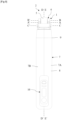
- the massage device 2 preferably comprises a main body 7 forming a handle 8 (or handle) for manual gripping, and typically comprising a working end 9 at which the massage head is fixed, preferably in a removable manner. 1 according to the invention.
- Said main body 7 can, for example, be formed of two half-shells 7A, 7B assembled together, preferably in a watertight manner, so as to define on the one hand an exterior surface forming a gripping area of the massage device 2 by the user and, on the other hand, an internal space within which the various functional elements necessary for the proper functioning of the massage device 2 can be housed and, in particular, to that of the massage head 1.
- the main body 7 could be formed of a single, monolithic shell, within which said functional elements would be inserted.
- the massage device 2 advantageously comprises an on-board motorization means (or motor), and preferably housed within said main body 7, which is intended to be mechanically connected to the drive system of the first and second rollers 4, 5 of the massage head 1 to ensure the rotation of the latter.
- it is a means of motorization with an electric motor (for example, a direct current motor, preferably servo-controlled).
- the motorization means could be of the pneumatic type (for example, an air turbine) or other.
- the motorization means can also include a gear motor arranged at the output of the electric motor or the air turbine to reduce the rotation speed and adapt it to the need for use.
- the massage device 2 may further optionally comprise a control unit (electromechanical or electronic) for the general operation of the massage device 2 via which the user can turn the massage device on/off 2, adjust the general operating mode or even adjust certain specific parameters (for example, the speed of rotation of rollers 4, 5, the direction of rotation of rollers 4, 5, etc.).
- the control unit can be advantageously arranged in the main body 7 of the massage device 2 and be accessible to the user via a control panel 10.
- the massage device 2 can also optionally include a block of power supply.
- the latter can, for example, include a battery of replaceable or rechargeable electrical accumulators arranged within the main body 7 of the massage device 2 to allow autonomous, nomadic use of the latter, or include an on-board electrical transformer or not, and intended to be connected to a conventional electrical outlet via an external power cord (not illustrated).
- a battery of replaceable or rechargeable electrical accumulators arranged within the main body 7 of the massage device 2 to allow autonomous, nomadic use of the latter, or include an on-board electrical transformer or not, and intended to be connected to a conventional electrical outlet via an external power cord (not illustrated).
- the main body 7 and the massage head 1 of the device 2 are integral with each other, so that the massage head 1 cannot, in normal use, be separated from said main body 7 by the user.
- the massage device 2 comprises removable means for coupling the massage head 1 to said main body 7, for example by nesting, so that the massage head 1 is thus assembled to the body main body 7 temporarily, not permanently, and can thus be separated from the main body 7 by the user, for example for maintenance purposes or replacement of the massage head 1.
- the drive system of the massage head 1, mentioned above, is more specifically designed to rotate the first and second rollers 4, 5 in a counter-rotating manner.
- the drive system is provided to ensure the simultaneous rotation of the first and second rollers 4, 5, respectively around the first axis A-A' and the second axis of rotation B-B', in directions of rotation opposite, inverted.
- the drive system advantageously prohibits said first and second rollers 4, 5 from any rotation in the same direction, as well as any free rotation around their respective axes A-A', B-B'.
- the drive system can be designed, by means of any known mechanism of gears, pulleys, belts, etc., so as to mechanically transmit to the first and second rollers 4, 5 the movement of the means motorization of the massage device 2, when the massage head 1 is connected to the main body 7 of the massage device 2.
- the drive system is designed to rotate said first and second rollers 4, 5, preferably in a synchronized manner, so that, in a plan view perpendicular to said first and second axes A-A' , BB' with the first and second rollers 4, 5 arranged at the top, the part of the roller located on the left which protrudes from said application surface rotates in the anti-trigonometric direction (or clockwise direction), while the part of the roller located to the right which protrudes from said application surface 6 rotates in the trigonometric direction (or counterclockwise direction).
- the massage head 1 when the first and second rollers 4, 5 are positioned in contact with the skin, their rotational movement causes a wrinkling effect on the skin between the first and second rollers 4, 5.
- the massage head 1 can then advantageously be used to implement the massage technique known as " palpate-roll " which in particular allows the activation of venous and lymphatic circulation and softening of the skin, by stimulating fibroblasts and accelerating the production of collagen, elastin and hyaluronic acid, by kneading the skin.
- the drive system is designed to rotate said first and second rollers 4, 5, preferably in a synchronized manner, so that, in a plan view perpendicular to said first and second axes A-A' , BB' with the first and second rollers 4, 5 arranged at the top, the part of the roller located on the left which protrudes from said application surface 6 rotates in the trigonometric direction (or counterclockwise direction), while the part of the roller located to the right which protrudes from said application surface 6 rotates in the anti-trigonometric direction (or clockwise direction).
- the massage head 1 when the first and second rollers 4, 5 are positioned in contact with the skin, their rotational movement causes a stretching effect on the skin.
- the drive system is designed to rotate said first and second rollers 4, 5 alternately according to the first (folding) and the second (stretching) variants above, according to the choice of the user (for example, by action of the latter on the control panel 10).
- each of these first and second massage rollers 4, 5 is of generally substantially cylindrical shape with a circular base, so that the space which separates their respective surfaces is constant along the first and second axes A-A', B-B'.
- the surface (or external part) of the first and/or second rollers 4, 5 may have a substantially smooth appearance or, on the contrary, present different shapes or structures, such as, for example, example, beads, hooks, pins, pallets or others, in particular in order to promote the grip of the skin by at least one of the rollers 4, 5.
- the first and/or second rollers 4, 5 (or at least the part of the latter which defines the surface or external part) can be in a material which is substantially hard and devoid of elasticity, or on the contrary in a material having a certain elasticity (for example in elastomer) to promote the grip of the skin by at least one of the rollers 4, 5 and improve the comfort of use.
- spacing we mean here the space, the distance, separating the respective surfaces of the rollers 4, 5.
- the system for adjusting the relative position of the first and second rollers 4, 5 modifies the spacing of the first and second rollers 4, 5 as a function of the intensity of the external forces exerted against at least the second roller 5 (and preferably, against the first and second rollers 4, 5) by the user's skin, which efforts generally tend to move the first and second rollers 4, 5 away from each other.
- distances d min and d max are considered here as corresponding to the minimum and maximum distances which separate two given points of the respective surface of the first and second rollers 4, 5 positioned facing each other, in a plane containing the axes A-A', BB' of the rollers 4, 5, respectively when the second roller 5 occupies its first position and when it occupies its second position.
- the minimum distances d min and maximum d max can advantageously be chosen differently depending in particular on the area of skin of the body to be treated, in order to optimize the effectiveness of the massage and the comfort of use.
- the minimum spacing E min will advantageously be defined so that the minimum distance d min between the first and second rollers 4, 5 is preferably equal to approximately 6 mm, while the maximum spacing E min will advantageously be defined so that the maximum distance d max between the first and second rollers 4, 5 is preferably equal to approximately 10 mm.
- the minimum spacing E min could advantageously be defined so that the minimum distance d min between the first and second rollers 4, 5 is preferably equal to approximately 10 mm, while the maximum spacing E min can advantageously be defined so that the maximum distance d max between the first and second rollers 4, 5 is preferably equal to approximately 15 mm.
- the minimum spacing E min can be advantageously defined so that the minimum distance d min between the first and second rollers 4, 5 is preferably equal to approximately 5 mm, while that the maximum spacing E min can advantageously be defined so that the maximum distance d max between the first and second rollers 4, 5 is preferably equal to approximately 10 mm.
- the system for adjusting the relative position of said first and second rollers 4, 5 is also designed to keep the first and second rollers 4, 5 initially spaced apart from each other in the absence of any external force exerted against at least the second roller 5.
- the adjustment system is provided to ensure an initial spacing E ini (non-zero) of the first and second rollers 4, 5 even though the latter are not in contact with the user's skin and the massage head is at rest, or even stopped.
- the existence of such an initial spacing between the first and second rollers 4, 5 advantageously promotes immediate and tonic massage (by pleating or stretching, depending on the direction of rotation of the rollers 4, 5) and toning of the skin upon application. against the latter of the massage head 1.
- this initial spacing E ini also advantageously makes it possible to facilitate the insertion of the skin within the working zone as soon as the The user applies the rollers 4, 5 in contact with his skin. This insertion is carried out remarkably painlessly, effortlessly and even without any special handling on the part of the user. The ease of use and ergonomics of the massage head 1 are therefore improved.
- the first and second rollers 4, 5 can thus advantageously be initially kept apart from each other by an initial distance of at least 2 to 8 mm, and more preferably at least 5 mm (or even 6 mm).
- the adjustment system is designed to maintain the first and second rollers 4, 5 at an initial spacing E ini identical to the minimum spacing E min described above. In other words, even in the absence of force exerted by the skin against at least the second roller 5, the adjustment system then maintains the second axis BB' in its first position. Said second position of the second axis BB' is therefore a rest position. This contributes to further simplifying the design of the system for adjusting the relative position of the rollers 4, 5, and more generally of the massage head 1.
- the system for adjusting the relative position of the first and second massage rollers 4, 5 is designed and configured so that the movement of the second axis B-B' between said first and second positions follows an arcuate trajectory, with a center of curvature advantageously positioned towards the inside of the frame 3.
- Such a configuration advantageously makes it easier to adjust the relative spacing of the first and second rollers 4, 5 under the effect of the pressure exerted by the user, depending on the topography of the area of skin to be treated.
- the adjustment system preferably comprises, on the one hand, a first support means 11 of the first roller 4, which first support means 11 is immobile relative to the frame 3 and, on the other hand, a second support means 12 of the second roller 5, distinct from said first support means 11, and which is in turn mounted to pivot relative to the frame 3 around a third axis (or third direction) CC' parallel to said first AA' and second BB' axes.
- the first and second support means 11, 12 are respectively designed to support the first and second rollers 4, 5 to rotate around the first and second axes A-A', B-B', for example via a first rigid axis (not visible in the figures) and a second rigid axis 13 (for example, in the form of stainless steel rods) which pass axially respectively through the first and second massage rollers 4, 5, and thus advantageously form rigid axes of rotation of said rollers 4, 5.
- said third axis CC' is advantageously positioned under the application surface 6, so that the center of curvature of the circular arc trajectory of the second axis BB' is positioned towards the inside of the frame 3.
- the first support means 11 may come from the material with all or part of the frame 3.
- the first support means 11 is itself advantageously formed by two complementary support elements 11A, 11B each forming a single, monolithic part, with one of the two two half-shells 3A, 3B.
- the second support means 12 can be formed from a single, monolithic piece, mounted on the one hand to pivot relative to the frame 3 via a third rigid axis (not visible in the figures), according to the principle of a pivot connection, and connected on the other hand to the second roller 5 via said second rigid axis 13. The manufacture and assembly of the massage head 1 is thus facilitated, while guaranteeing mobility of the second support means 12, and therefore of the second roller 5.
- the first and second support means 11, 12 advantageously define the application surface 6 of the massage head 1 mentioned above.
- the application surface 6 also constitutes a support surface, a sort of guide, allowing the user not to push the rollers 4, 5 too far into the skin, so as to optimize ergonomics and safety of use. of the massage head 1.
- the first and second support means 11, 12 are shaped so as to advantageously limit the risks of pinching the user's skin or fingers between the frame 3 and the first and second massage rollers 4, 5.
- the massage head 1 comprises a return member 14 configured and arranged to exert a force tending to return the second extension axis BB' of the second massage roller 5 towards said first position when it occupies said second position .
- the return member 14 thus has the effect of bringing the first and second rollers 4, 5 closer together, when the latter are moved away from each other under the effect, in particular of external forces exerted against the less of said second roller 5 by the user's skin.
- the implementation of such a return member 14 advantageously makes it possible to give the system for adjusting the relative position of the axes A-A', BB' of the rollers 4, 5 a dynamic character, in particular favoring permanent contact between the first and second rollers 4, 5 and the skin during the treatment of the latter using the massage head 1.
- Such a return member 14 also advantageously allows the adjustment system to adjust the spacing of the first and second rollers 4, 5 until reaching a balance of the forces exerted directly and/or indirectly on these rollers 4, 5.
- the forces exerted by the skin against at least the second roller 5, when they are greater than the forces exerted by the return member 14, make it possible to counter the return effect of the return member 14 and to move the rollers 4, 5 apart by moving the second roller 5 towards its second position .
- the forces exerted by the skin against at least the second roller 5 are lower than the forces respectively exerted by the return member 14, the latter recalls the second roller 5 towards its first position, which thus brings closer the first and second rollers 4, 5, until reaching an equilibrium position.
- the implementation of the return member 14 makes it possible to choose by design, the maximum admissible force within the working zone, that is to say between the first and second rollers 4, 5, and therefore to do not leave the assessment of this effort (which arises in particular from the pressure applied to the skin) to the user of the head of massage 1, as could be the case with the massage heads of the prior art.
- This thus considerably strengthens the safety and ease of use of the massage head 1 and the device 2 objects of the invention, allowing in particular their use by an unqualified user (that is to say not having special knowledge in the field of massage).
- the return member 14 can be of any known suitable type, and can for example comprise one or more helical tension or compression springs (" coil " springs), one or more helical torsion springs, one or more springs with blade(s), or a combination of these.
- the return member 14 comprises a single helical torsion spring 15, one of the legs of which is positioned bearing against a surface of the frame 3 and the other of the legs is positioned bearing against a surface of the second means of support 12 of the second roller 5, and whose turns are wound around the third shaft which connects the second support means 12 to the frame 3.
- other arrangements and configurations of the return member 14 could be retained, without however, going beyond the scope of the invention, to obtain the desired recall effect.
- the tare of the return member 14, and in particular its return force is chosen, according to the intended application and the skin area to be treated, as a function of the resistance threshold of the skin.
- the second roller 5 approaches the first roller 4 under the effect of the return member 14.
- the return force of the return member 14 is on the contrary lower than the resistance force of the skin, so that the second roller 5 tends to move away from the first roller 4, its second axis d 'B-B extension' moving to its second position. This improves both the effectiveness and the comfort of the massage of the skin by the massage head 1, while guaranteeing the safety of use of the massage head 1 by an unqualified user.
- the return member 14 is calibrated so that it exerts a return force from the second axis B-B', from its second position towards its first position, which is between 2 N and 20 N, and preferably again between 4 N and 10 N.
- the torque of this helical spring 15 of torsion can advantageously be between 10 Nmm and 50 Nmm, even more advantageously between 20 and 40 Nmm.
- Such calibration is in fact particularly well suited for the treatment, using the massage head 1, of an area of facial skin using the so-called “ palpate-roll ” technique mentioned previously.
- the first and second positions of the second axis BB' of extension and rotation of the second roller 5 are stop positions, so as to mechanically limit, in a reliable and repeatable manner, the relative spacing range of the first and second rollers 4, 5.
- said first and second positions are defined by fixed mechanical stops, defined once and for all during the design of the massage head 1. No particular adjustment is required. is thus required from the user.
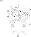
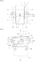
- the second position of the second axis BB' of the second roller 5 is defined by two fixed lateral stops 16A, 16B arranged at the level of the second support means 12 ( figures 1 And 2 ), and which come to bear against an external surface of the housing 3, which forms the frame 3 of the massage head 1, when the second axis BB' occupies its second position ( figures 5 And 6 ).
- a single fixed stop could alternatively be considered.
- the stops 16A, 16B are designed and dimensioned to ensure that the surface of the second roller 5 is maintained at a distance from the frame 3, so as to avoid any contact between the latter when the second axis BB' of rotation of the second roller 5 occupies its second position.
- the first position of the second axis BB' of the second roller 5 can be defined, for example, by at least one fixed stop (and preferably two, not visible in the figures) arranged at the level of the second support means 12, and which comes to bear against a surface of the first support means 11 of the first roller 4 when the second axis BB' occupies its first position.
- this fixed stop also makes it possible to avoid advantageously any interaction between the second support means 12 and the drive system housed within the housing 3.
- said first and second positions could on the contrary be one and/or the other defined by adjustable mechanical stops (for example, screw), so that the user can define and adjust himself the value of the minimum E min and maximum E max spacing desired.
- the massage head 1 can then be advantageously designed and configured so as to define a plane P 1 of contact of the first and second rollers 4, 5 with the skin which is oriented in a intersecting manner and not orthogonal to said fourth axis DD' of extension of the frame 3 of the massage head 1, and this, more preferably, whatever the (first or second) position occupied by the second axis BB' of extension and rotation of the second roller 5.
- this plane P 1 of contact of the first and second rollers 4, 5 with the skin is intersecting and not orthogonal to the fourth axis DD' according to a minimum contact angle ⁇ min of at least 15°, when the second axis BB' occupies its first position, and at a maximum contact angle ⁇ max of 110° at most when the second axis BB' occupies its second position respectively.
- ⁇ min minimum contact angle
- ⁇ max maximum contact angle
- the angle minimum contact angle ⁇ min could advantageously be chosen equal to 72.5°, while the maximum contact angle ⁇ max could advantageously be chosen equal to 91.5°.
- the third pivot axis CC' of the second support means 12 of the second roller 5 relative to the frame 3 of the massage head 1 could be included in a plane containing the fourth axis DD' of extension of said frame 3, which contributes to the simplicity of design and the compactness of the massage head 1.
- the system for adjusting the relative position of the first and second rollers 4, 5 can advantageously be designed and configured so as to define between, on the one hand a plane P 2 comprising the first axis AA' and the third axis CC' and, on the other hand a plane P 3 comprising the second axis BB' and the third axis C-C', a minimum opening angle ⁇ min between 95° and 110° (and preferably equal to 105°) when said second axis BB' occupies its first position, and a maximum opening angle ⁇ max between 135° and 150° (and preferably equal to 143°) when said second axis BB' respectively occupies said second position.
Landscapes
- Health & Medical Sciences (AREA)
- Epidemiology (AREA)
- Pain & Pain Management (AREA)
- Physical Education & Sports Medicine (AREA)
- Rehabilitation Therapy (AREA)
- Life Sciences & Earth Sciences (AREA)
- Animal Behavior & Ethology (AREA)
- General Health & Medical Sciences (AREA)
- Public Health (AREA)
- Veterinary Medicine (AREA)
- Massaging Devices (AREA)
Claims (16)
- Massagekopf (1) für eine Massageeinrichtung, umfassend- ein Gehäuse (3),- eine erste Massagerolle (4) und eine zweite Massagerolle (5), die dazu bestimmt sind, mit der Haut eines Benutzers in Kontakt zu kommen, wobei sich die erste Massagerolle (4) längs entlang einer ersten Achse (A-A') erstreckt, um die die erste Rolle (4) drehbar in Bezug auf das Gehäuse (3) angebracht ist, wobei sich die zweite Massagerolle (5) längs entlang einer zweiten Achse (B-B') erstreckt, die parallel zur ersten Achse (A-A') ist und um die die zweite Rolle (5) drehbar in Bezug auf das Gehäuse (3) angebracht ist,- ein Antriebssystem, das dazu ausgelegt ist, die erste und die zweite Rolle (4, 5) gegenläufig drehend anzutreiben,dadurch gekennzeichnet, dass der Massagekopf ein System zum Anpassen der relativen Position der ersten und der zweiten Rolle (4, 5) in Reaktion auf äußere Kräfte, die während der Drehung der zweiten Rolle (5) von der Haut des Benutzers gegen mindestens die zweite Rolle (5) ausgeübt werden, umfasst, wobei das Anpasssystem so ausgelegt und konfiguriert ist, dass es die erste Achse (A-A') in Bezug auf das Gehäuse (3) feststehend hält, während es zugleich eine Verlagerung der zweiten Achse (B-B') in Reaktion auf die äußeren Kräfte, die von der Haut des Benutzers gegen mindestens die zweite Rolle (5), während diese dreht, ausgeübt werden, zwischen einer ersten Position, die einen minimalen Abstand (Emin) zwischen der ersten und der zweiten Rolle (4, 5) definiert, und einer zweiten Position, die einen maximalen Abstand (Emax) zwischen der ersten und der zweiten Rolle (4, 5) definiert, zulässt.
- Massagekopf (1) nach dem vorstehenden Anspruch, wobei das Anpasssystem so ausgelegt ist, dass es die erste und die zweite Rolle (4, 5) anfänglich voneinander beabstandet hält, wenn keine äußere Kraft gegen mindestens die zweite Rolle (5) ausgeübt wird.
- Massagekopf (1) nach dem vorstehenden Anspruch, wobei die erste und die zweite Rolle (4, 5) anfänglich um einen anfänglichen Abstand von mindestens 2 bis 8 mm, und vorzugsweise von mindestens 5 mm, voneinander beabstandet gehalten werden.
- Massagekopf (1) nach einem der vorstehenden Ansprüche, wobei der minimale (Emin) und der maximale Abstand (Emax) so definiert sind, dass:- wenn die zweite Achse (B-B') die erste Position einnimmt, die erste und die zweite Rolle (4, 5) um einen minimalen Abstand (dmin) im Bereich zwischen 2 bis 10 mm, vorzugsweise zwischen 4 und 8 mm und weiter bevorzugt von gleich 6 mm voneinander beabstandet sind;- wenn die zweite Achse (B-B') die zweite Position einnimmt, die erste und die zweite Rolle (4, 5) um einen maximalen Abstand (dmax) im Bereich zwischen 8 bis 20 mm, vorzugsweise zwischen 10 und 12 mm und weiter bevorzugt von gleich 10 mm voneinander beabstandet sind.
- Massagekopf (1) nach einem der vorstehenden Ansprüche, der eine Anwendungsfläche (6) umfasst, die dazu bestimmt ist, der Oberfläche der Haut des Benutzers zugewandt positioniert zu werden, wobei die erste und die zweite Rolle (4, 5) mindestens teilweise an der Außenseite der Anwendungsfläche (6) überstehen.
- Massagekopf (1) nach dem vorstehenden Anspruch, wobei das Antriebssystem so ausgelegt ist, dass es die erste und die zweite Rolle (4, 5), vorzugsweise synchronisiert, drehend so antreibt, dass in einer Draufsicht senkrecht zu der ersten und der zweiten Achse (A-A', B-B'), wenn die erste und die zweite Rolle (4, 5) oben angeordnet sind, der Teil der links befindlichen Rolle, der von der Anwendungsfläche (6) übersteht, im Gegenuhrzeigersinn dreht, während der Teil der rechts befindlichen Rolle, der von der Anwendungsfläche (6) übersteht, im Uhrzeigersinn dreht.
- Massagekopf (1) nach einem der vorstehenden Ansprüche, wobei das Anpasssystem so ausgelegt und konfiguriert ist, dass die Verlagerung der zweiten Achse (B-B') zwischen der ersten und der zweiten Position einer kreisbogenförmigen Bahn folgt.
- Massagekopf (1) nach dem vorstehenden Anspruch, wobei das Anpasssystem ein erstes Mittel zum Tragen (11) der ersten Rolle (5), wobei das erste Tragmittel (11) in Bezug auf das Gehäuse (3) unbeweglich ist, und ein zweites Mittel zum Tragen (12) der zweiten Rolle (5) umfasst, wobei das zweite Tragmittel (12) in Bezug auf das Gehäuse (3) um eine dritte Achse (C-C'), die zu der ersten (A-A') und der zweiten (B-B') Achse parallel ist, schwenkend angebracht ist.
- Massagekopf (1) nach einem der vorstehenden Ansprüche, wobei die erste und die zweite Position Anschlagpositionen sind.
- Massagekopf (1) nach einem der vorstehenden Ansprüche, der ein Rückstellorgan (14) umfasst, das so konfiguriert und eingerichtet ist, dass es eine Kraft ausübt, die dazu neigt, die zweite Erstreckungsachse (B-B') der zweiten Massagerolle (5) in Richtung der ersten Position zurückzustellen, wenn sie die zweite Position einnimmt.
- Massagekopf (1) nach einem der vorstehenden Ansprüche, wobei sich das Gehäuse (3) entlang einer vierten Achse (D-D') erstreckt zwischen- einem distalen Ende (17), an dem der Massagekopf (1) bestimmt ist, mit einem Handgriff (8) von allgemein länglicher Form entlang einer fünften Achse (E-E') so verbunden zu werden, dass die vierte und die fünfte Achse (D-D', E-E') parallel sind oder sich decken,- und einem gegenüberliegenden proximalen Ende, wobei der Massagekopf (1) so ausgelegt und konfiguriert ist, dass er eine Kontaktebene (P1) der ersten und der zweiten Rolle (4, 5) mit der Haut definiert, die nicht orthogonal zur vierten Achse (D-D') und diese schneidend ausgerichtet ist, vorzugsweise unabhängig davon, welche Position die zweite Achse (B-B') einnimmt.
- Massagekopf (1) nach dem vorstehenden Anspruch, wobei die Kontaktebene (P1) der ersten und der zweiten Rolle (4, 5) mit der Haut nicht orthogonal zur vierten Achse (D-D') ist und diese in einem minimalen Kontaktwinkel (αmin) von mindestens 15° und vorzugsweise von gleich 72,5°, wenn die zweite Achse (B-B') die erste Position einnimmt, und in einem maximalen Kontaktwinkel (αmax) von höchstens 110° und vorzugsweise von gleich 91,5° schneidet, wenn die zweite Achse (B-B') jeweils die zweite Position einnimmt.
- Massageeinrichtung (2), die einen Massagekopf (1) nach einem der vorstehenden Ansprüche umfasst.
- Einrichtung (2) nach dem vorstehenden Anspruch, die einen Hauptkörper (7) umfasst, der einen Handgriff (8) bildet, wobei der Massagekopf (1) an einem Arbeitsende (9) des Hauptkörpers (7) befestigt ist.
- Einrichtung (2) nach dem vorstehenden Anspruch, die Mittel zum abnehmbaren Koppeln des Massagekopfes (1) an den Hauptkörper (7) umfasst.
- Einrichtung (2) nach einem der Ansprüche 13 bis 15, die ein integriertes Motorisierungsmittel, vorzugsweise mit Elektromotor, umfasst, das dazu bestimmt ist, mechanisch mit dem Antriebssystem verbunden zu werden, um die Drehbewegung der ersten und der zweiten Massagerolle (4, 5) des Massagekopfes (1) sicherzustellen.
Applications Claiming Priority (2)
| Application Number | Priority Date | Filing Date | Title |
|---|---|---|---|
| FR1906683A FR3097431B1 (fr) | 2019-06-20 | 2019-06-20 | Tete de massage amelioree pour appareil de massage et appareil de massage equipe d’une telle tete |
| PCT/EP2020/066573 WO2020254297A1 (fr) | 2019-06-20 | 2020-06-16 | Tete de massage amelioree pour appareil de massage et appareil de massage equipe d'une telle tete |
Publications (2)
| Publication Number | Publication Date |
|---|---|
| EP3986355A1 EP3986355A1 (de) | 2022-04-27 |
| EP3986355B1 true EP3986355B1 (de) | 2023-09-27 |
Family
ID=67810939
Family Applications (1)
| Application Number | Title | Priority Date | Filing Date |
|---|---|---|---|
| EP20731887.4A Active EP3986355B1 (de) | 2019-06-20 | 2020-06-16 | Verbesserter massagekopf für massagevorrichtung und massagevorrichtung mit einem solchen kopf |
Country Status (5)
| Country | Link |
|---|---|
| EP (1) | EP3986355B1 (de) |
| KR (1) | KR20220024634A (de) |
| CN (1) | CN113993494B (de) |
| FR (1) | FR3097431B1 (de) |
| WO (1) | WO2020254297A1 (de) |
Citations (1)
| Publication number | Priority date | Publication date | Assignee | Title |
|---|---|---|---|---|
| EP0538142B1 (de) * | 1991-10-18 | 1995-08-02 | Seb S.A. | Rollenmassagegerät |
Family Cites Families (16)
| Publication number | Priority date | Publication date | Assignee | Title |
|---|---|---|---|---|
| FR934070A (fr) * | 1946-10-01 | 1948-05-11 | Appareil de massage | |
| FR2579100B1 (fr) * | 1985-03-19 | 1989-03-03 | Guitay Louis Paul | Appareil pour le massage du corps humain |
| FR2746320B1 (fr) * | 1996-03-20 | 1998-06-05 | Seb Sa | Appareil de stimulation electrique indolore et procede correspondant |
| CN1165270C (zh) * | 1996-07-15 | 2004-09-08 | 皇家菲利浦电子有限公司 | 有两个滚轮和一个抽吸腔室的按摩装置 |
| FR2771000B1 (fr) * | 1997-11-17 | 2000-01-14 | Jean Frajdenrajch | Appareil de massage perfectionne |
| JP4470586B2 (ja) * | 2004-05-26 | 2010-06-02 | パナソニック電工株式会社 | マッサージ装置 |
| FR2902318B1 (fr) * | 2006-06-19 | 2009-01-30 | Louisin Res And Dev Ltd | Dispositif de traitement, notamment de massage, du tissu conjonctif de la peau |
| FR2919493B1 (fr) * | 2007-07-30 | 2010-07-30 | Oreal | Dispositif de massage |
| FR2934775B1 (fr) * | 2008-08-08 | 2010-08-27 | Lpg Finance Ind | Tete de massage et appareil de massage mettant en oeuvre une telle tete |
| CN202236190U (zh) * | 2011-09-24 | 2012-05-30 | 钱建明 | 自适应柔性按摩器械 |
| FR2998171B1 (fr) * | 2012-11-22 | 2021-03-26 | Seb Sa | Appareil de massage avec tete de massage equipee de rouleaux de massage |
| FR2998168B1 (fr) * | 2012-11-22 | 2023-04-28 | Seb Sa | Appareil de massage equipe de tetes de massage interchangeables |
| FR3012035B1 (fr) * | 2013-10-17 | 2016-01-01 | Seb Sa | Appareil de massage avec tete de massage equipee d'un rouleau a palette et d'un rouleau a surface de type lisse |
| FR3021868B1 (fr) * | 2014-06-06 | 2016-05-27 | Lpg Systems | Tete de massage et appareil de massage mettant en œuvre une telle tete |
| JP3206001U (ja) * | 2016-06-14 | 2016-08-25 | ドクターセラム株式会社 | マッサージ器具 |
| CN206822833U (zh) * | 2016-12-30 | 2018-01-02 | 李子成 | 肌肉按摩器 |
-
2019
- 2019-06-20 FR FR1906683A patent/FR3097431B1/fr not_active Expired - Fee Related
-
2020
- 2020-06-16 CN CN202080044214.2A patent/CN113993494B/zh active Active
- 2020-06-16 KR KR1020227001597A patent/KR20220024634A/ko not_active Ceased
- 2020-06-16 EP EP20731887.4A patent/EP3986355B1/de active Active
- 2020-06-16 WO PCT/EP2020/066573 patent/WO2020254297A1/fr not_active Ceased
Patent Citations (1)
| Publication number | Priority date | Publication date | Assignee | Title |
|---|---|---|---|---|
| EP0538142B1 (de) * | 1991-10-18 | 1995-08-02 | Seb S.A. | Rollenmassagegerät |
Also Published As
| Publication number | Publication date |
|---|---|
| CN113993494B (zh) | 2024-07-16 |
| KR20220024634A (ko) | 2022-03-03 |
| WO2020254297A1 (fr) | 2020-12-24 |
| FR3097431B1 (fr) | 2022-09-23 |
| EP3986355A1 (de) | 2022-04-27 |
| CN113993494A (zh) | 2022-01-28 |
| FR3097431A1 (fr) | 2020-12-25 |
Similar Documents
| Publication | Publication Date | Title |
|---|---|---|
| EP2735297B1 (de) | Massagegerät mit einem Massagekopf, der mit Massagerollen ausgestattet ist | |
| EP2862556B1 (de) | Massagegerät mit einem Massagekopf, der mit einem Klopffinger ausgestattet ist | |
| EP2922518B2 (de) | Massagevorrichtung mit auswechselbaren und identifizierten massageköpfen | |
| EP2862554B1 (de) | Massagegerät mit mindestens einem Massagekopf mit exzentrischer Drehung | |
| FR2514255A1 (fr) | Dispositif de traitement de beaute | |
| FR2589726A1 (fr) | Appareil pour le massage du corps humain | |
| EP3731693B1 (de) | Haarstyling-gerät mit verbesserter kinematik | |
| EP3986355B1 (de) | Verbesserter massagekopf für massagevorrichtung und massagevorrichtung mit einem solchen kopf | |
| EP4262671B1 (de) | Massagekopf mit optimiertem antrieb für massagevorrichtung und massagevorrichtung mit solch einem kopf | |
| EP2671465B1 (de) | Epilationskopf zur schmerzfreien Haarentfernung | |
| FR2965154A1 (fr) | Epilateur avec tete de massage amovible | |
| EP4196071B1 (de) | Einklemmschutz-massagekopf und vorrichtung | |
| EP1351590B1 (de) | Epilationsgerät mit einer vorrichtung zur verminderung von schmerzen | |
| EP0666071A1 (de) | Gerät für die Gesichtsmassage | |
| EP4125770A1 (de) | Massagegerät mit auswechselbaren und identifizierbaren massageköpfen | |
| EP3766377B1 (de) | Epilationskopf-rolle für epilationsgerät, epilationskopf und epilationsgerät, die mit einer solchen rolle ausgestattet sind | |
| FR2772262A1 (fr) | Appareil de massage et de succion cutane | |
| FR3006867A1 (fr) | Dispositif de massage et/ou d'application de produit cosmetique, et procede associe |
Legal Events
| Date | Code | Title | Description |
|---|---|---|---|
| STAA | Information on the status of an ep patent application or granted ep patent |
Free format text: STATUS: UNKNOWN |
|
| STAA | Information on the status of an ep patent application or granted ep patent |
Free format text: STATUS: THE INTERNATIONAL PUBLICATION HAS BEEN MADE |
|
| PUAI | Public reference made under article 153(3) epc to a published international application that has entered the european phase |
Free format text: ORIGINAL CODE: 0009012 |
|
| STAA | Information on the status of an ep patent application or granted ep patent |
Free format text: STATUS: REQUEST FOR EXAMINATION WAS MADE |
|
| 17P | Request for examination filed |
Effective date: 20220106 |
|
| AK | Designated contracting states |
Kind code of ref document: A1 Designated state(s): AL AT BE BG CH CY CZ DE DK EE ES FI FR GB GR HR HU IE IS IT LI LT LU LV MC MK MT NL NO PL PT RO RS SE SI SK SM TR |
|
| DAV | Request for validation of the european patent (deleted) | ||
| DAX | Request for extension of the european patent (deleted) | ||
| GRAP | Despatch of communication of intention to grant a patent |
Free format text: ORIGINAL CODE: EPIDOSNIGR1 |
|
| STAA | Information on the status of an ep patent application or granted ep patent |
Free format text: STATUS: GRANT OF PATENT IS INTENDED |
|
| INTG | Intention to grant announced |
Effective date: 20230509 |
|
| GRAS | Grant fee paid |
Free format text: ORIGINAL CODE: EPIDOSNIGR3 |
|
| GRAA | (expected) grant |
Free format text: ORIGINAL CODE: 0009210 |
|
| STAA | Information on the status of an ep patent application or granted ep patent |
Free format text: STATUS: THE PATENT HAS BEEN GRANTED |
|
| AK | Designated contracting states |
Kind code of ref document: B1 Designated state(s): AL AT BE BG CH CY CZ DE DK EE ES FI FR GB GR HR HU IE IS IT LI LT LU LV MC MK MT NL NO PL PT RO RS SE SI SK SM TR |
|
| REG | Reference to a national code |
Ref country code: GB Ref legal event code: FG4D Free format text: NOT ENGLISH |
|
| REG | Reference to a national code |
Ref country code: CH Ref legal event code: EP |
|
| REG | Reference to a national code |
Ref country code: DE Ref legal event code: R096 Ref document number: 602020018300 Country of ref document: DE |
|
| REG | Reference to a national code |
Ref country code: IE Ref legal event code: FG4D Free format text: LANGUAGE OF EP DOCUMENT: FRENCH |
|
| REG | Reference to a national code |
Ref country code: LT Ref legal event code: MG9D |
|
| PG25 | Lapsed in a contracting state [announced via postgrant information from national office to epo] |
Ref country code: GR Free format text: LAPSE BECAUSE OF FAILURE TO SUBMIT A TRANSLATION OF THE DESCRIPTION OR TO PAY THE FEE WITHIN THE PRESCRIBED TIME-LIMIT Effective date: 20231228 |
|
| PG25 | Lapsed in a contracting state [announced via postgrant information from national office to epo] |
Ref country code: SE Free format text: LAPSE BECAUSE OF FAILURE TO SUBMIT A TRANSLATION OF THE DESCRIPTION OR TO PAY THE FEE WITHIN THE PRESCRIBED TIME-LIMIT Effective date: 20230927 Ref country code: RS Free format text: LAPSE BECAUSE OF FAILURE TO SUBMIT A TRANSLATION OF THE DESCRIPTION OR TO PAY THE FEE WITHIN THE PRESCRIBED TIME-LIMIT Effective date: 20230927 Ref country code: NO Free format text: LAPSE BECAUSE OF FAILURE TO SUBMIT A TRANSLATION OF THE DESCRIPTION OR TO PAY THE FEE WITHIN THE PRESCRIBED TIME-LIMIT Effective date: 20231227 Ref country code: LV Free format text: LAPSE BECAUSE OF FAILURE TO SUBMIT A TRANSLATION OF THE DESCRIPTION OR TO PAY THE FEE WITHIN THE PRESCRIBED TIME-LIMIT Effective date: 20230927 Ref country code: LT Free format text: LAPSE BECAUSE OF FAILURE TO SUBMIT A TRANSLATION OF THE DESCRIPTION OR TO PAY THE FEE WITHIN THE PRESCRIBED TIME-LIMIT Effective date: 20230927 Ref country code: HR Free format text: LAPSE BECAUSE OF FAILURE TO SUBMIT A TRANSLATION OF THE DESCRIPTION OR TO PAY THE FEE WITHIN THE PRESCRIBED TIME-LIMIT Effective date: 20230927 Ref country code: GR Free format text: LAPSE BECAUSE OF FAILURE TO SUBMIT A TRANSLATION OF THE DESCRIPTION OR TO PAY THE FEE WITHIN THE PRESCRIBED TIME-LIMIT Effective date: 20231228 Ref country code: FI Free format text: LAPSE BECAUSE OF FAILURE TO SUBMIT A TRANSLATION OF THE DESCRIPTION OR TO PAY THE FEE WITHIN THE PRESCRIBED TIME-LIMIT Effective date: 20230927 |
|
| REG | Reference to a national code |
Ref country code: NL Ref legal event code: MP Effective date: 20230927 |
|
| REG | Reference to a national code |
Ref country code: AT Ref legal event code: MK05 Ref document number: 1614701 Country of ref document: AT Kind code of ref document: T Effective date: 20230927 |
|
| PG25 | Lapsed in a contracting state [announced via postgrant information from national office to epo] |
Ref country code: NL Free format text: LAPSE BECAUSE OF FAILURE TO SUBMIT A TRANSLATION OF THE DESCRIPTION OR TO PAY THE FEE WITHIN THE PRESCRIBED TIME-LIMIT Effective date: 20230927 |
|
| PG25 | Lapsed in a contracting state [announced via postgrant information from national office to epo] |
Ref country code: IS Free format text: LAPSE BECAUSE OF FAILURE TO SUBMIT A TRANSLATION OF THE DESCRIPTION OR TO PAY THE FEE WITHIN THE PRESCRIBED TIME-LIMIT Effective date: 20240127 |
|
| PG25 | Lapsed in a contracting state [announced via postgrant information from national office to epo] |
Ref country code: AT Free format text: LAPSE BECAUSE OF FAILURE TO SUBMIT A TRANSLATION OF THE DESCRIPTION OR TO PAY THE FEE WITHIN THE PRESCRIBED TIME-LIMIT Effective date: 20230927 |
|
| PG25 | Lapsed in a contracting state [announced via postgrant information from national office to epo] |
Ref country code: ES Free format text: LAPSE BECAUSE OF FAILURE TO SUBMIT A TRANSLATION OF THE DESCRIPTION OR TO PAY THE FEE WITHIN THE PRESCRIBED TIME-LIMIT Effective date: 20230927 |
|
| PG25 | Lapsed in a contracting state [announced via postgrant information from national office to epo] |
Ref country code: SM Free format text: LAPSE BECAUSE OF FAILURE TO SUBMIT A TRANSLATION OF THE DESCRIPTION OR TO PAY THE FEE WITHIN THE PRESCRIBED TIME-LIMIT Effective date: 20230927 Ref country code: RO Free format text: LAPSE BECAUSE OF FAILURE TO SUBMIT A TRANSLATION OF THE DESCRIPTION OR TO PAY THE FEE WITHIN THE PRESCRIBED TIME-LIMIT Effective date: 20230927 Ref country code: IS Free format text: LAPSE BECAUSE OF FAILURE TO SUBMIT A TRANSLATION OF THE DESCRIPTION OR TO PAY THE FEE WITHIN THE PRESCRIBED TIME-LIMIT Effective date: 20240127 Ref country code: ES Free format text: LAPSE BECAUSE OF FAILURE TO SUBMIT A TRANSLATION OF THE DESCRIPTION OR TO PAY THE FEE WITHIN THE PRESCRIBED TIME-LIMIT Effective date: 20230927 Ref country code: EE Free format text: LAPSE BECAUSE OF FAILURE TO SUBMIT A TRANSLATION OF THE DESCRIPTION OR TO PAY THE FEE WITHIN THE PRESCRIBED TIME-LIMIT Effective date: 20230927 Ref country code: CZ Free format text: LAPSE BECAUSE OF FAILURE TO SUBMIT A TRANSLATION OF THE DESCRIPTION OR TO PAY THE FEE WITHIN THE PRESCRIBED TIME-LIMIT Effective date: 20230927 Ref country code: AT Free format text: LAPSE BECAUSE OF FAILURE TO SUBMIT A TRANSLATION OF THE DESCRIPTION OR TO PAY THE FEE WITHIN THE PRESCRIBED TIME-LIMIT Effective date: 20230927 Ref country code: SK Free format text: LAPSE BECAUSE OF FAILURE TO SUBMIT A TRANSLATION OF THE DESCRIPTION OR TO PAY THE FEE WITHIN THE PRESCRIBED TIME-LIMIT Effective date: 20230927 Ref country code: PT Free format text: LAPSE BECAUSE OF FAILURE TO SUBMIT A TRANSLATION OF THE DESCRIPTION OR TO PAY THE FEE WITHIN THE PRESCRIBED TIME-LIMIT Effective date: 20240129 |
|
| PG25 | Lapsed in a contracting state [announced via postgrant information from national office to epo] |
Ref country code: PL Free format text: LAPSE BECAUSE OF FAILURE TO SUBMIT A TRANSLATION OF THE DESCRIPTION OR TO PAY THE FEE WITHIN THE PRESCRIBED TIME-LIMIT Effective date: 20230927 Ref country code: IT Free format text: LAPSE BECAUSE OF FAILURE TO SUBMIT A TRANSLATION OF THE DESCRIPTION OR TO PAY THE FEE WITHIN THE PRESCRIBED TIME-LIMIT Effective date: 20230927 |
|
| REG | Reference to a national code |
Ref country code: DE Ref legal event code: R097 Ref document number: 602020018300 Country of ref document: DE |
|
| PGFP | Annual fee paid to national office [announced via postgrant information from national office to epo] |
Ref country code: GB Payment date: 20240626 Year of fee payment: 5 |
|
| PGFP | Annual fee paid to national office [announced via postgrant information from national office to epo] |
Ref country code: DE Payment date: 20240613 Year of fee payment: 5 |
|
| PG25 | Lapsed in a contracting state [announced via postgrant information from national office to epo] |
Ref country code: DK Free format text: LAPSE BECAUSE OF FAILURE TO SUBMIT A TRANSLATION OF THE DESCRIPTION OR TO PAY THE FEE WITHIN THE PRESCRIBED TIME-LIMIT Effective date: 20230927 |
|
| PG25 | Lapsed in a contracting state [announced via postgrant information from national office to epo] |
Ref country code: DK Free format text: LAPSE BECAUSE OF FAILURE TO SUBMIT A TRANSLATION OF THE DESCRIPTION OR TO PAY THE FEE WITHIN THE PRESCRIBED TIME-LIMIT Effective date: 20230927 |
|
| PGFP | Annual fee paid to national office [announced via postgrant information from national office to epo] |
Ref country code: FR Payment date: 20240624 Year of fee payment: 5 |
|
| PLBE | No opposition filed within time limit |
Free format text: ORIGINAL CODE: 0009261 |
|
| STAA | Information on the status of an ep patent application or granted ep patent |
Free format text: STATUS: NO OPPOSITION FILED WITHIN TIME LIMIT |
|
| 26N | No opposition filed |
Effective date: 20240628 |
|
| PG25 | Lapsed in a contracting state [announced via postgrant information from national office to epo] |
Ref country code: SI Free format text: LAPSE BECAUSE OF FAILURE TO SUBMIT A TRANSLATION OF THE DESCRIPTION OR TO PAY THE FEE WITHIN THE PRESCRIBED TIME-LIMIT Effective date: 20230927 |
|
| PG25 | Lapsed in a contracting state [announced via postgrant information from national office to epo] |
Ref country code: SI Free format text: LAPSE BECAUSE OF FAILURE TO SUBMIT A TRANSLATION OF THE DESCRIPTION OR TO PAY THE FEE WITHIN THE PRESCRIBED TIME-LIMIT Effective date: 20230927 |
|
| PG25 | Lapsed in a contracting state [announced via postgrant information from national office to epo] |
Ref country code: BG Free format text: LAPSE BECAUSE OF FAILURE TO SUBMIT A TRANSLATION OF THE DESCRIPTION OR TO PAY THE FEE WITHIN THE PRESCRIBED TIME-LIMIT Effective date: 20230927 |
|
| PG25 | Lapsed in a contracting state [announced via postgrant information from national office to epo] |
Ref country code: BG Free format text: LAPSE BECAUSE OF FAILURE TO SUBMIT A TRANSLATION OF THE DESCRIPTION OR TO PAY THE FEE WITHIN THE PRESCRIBED TIME-LIMIT Effective date: 20230927 |
|
| PG25 | Lapsed in a contracting state [announced via postgrant information from national office to epo] |
Ref country code: MC Free format text: LAPSE BECAUSE OF FAILURE TO SUBMIT A TRANSLATION OF THE DESCRIPTION OR TO PAY THE FEE WITHIN THE PRESCRIBED TIME-LIMIT Effective date: 20230927 |
|
| REG | Reference to a national code |
Ref country code: CH Ref legal event code: PL |
|
| PG25 | Lapsed in a contracting state [announced via postgrant information from national office to epo] |
Ref country code: LU Free format text: LAPSE BECAUSE OF NON-PAYMENT OF DUE FEES Effective date: 20240616 |
|
| PG25 | Lapsed in a contracting state [announced via postgrant information from national office to epo] |
Ref country code: IE Free format text: LAPSE BECAUSE OF NON-PAYMENT OF DUE FEES Effective date: 20240616 |
|
| PG25 | Lapsed in a contracting state [announced via postgrant information from national office to epo] |
Ref country code: BE Free format text: LAPSE BECAUSE OF NON-PAYMENT OF DUE FEES Effective date: 20240630 Ref country code: CH Free format text: LAPSE BECAUSE OF NON-PAYMENT OF DUE FEES Effective date: 20240630 |
|
| REG | Reference to a national code |
Ref country code: BE Ref legal event code: MM Effective date: 20240630 |
|
| PG25 | Lapsed in a contracting state [announced via postgrant information from national office to epo] |
Ref country code: CY Free format text: LAPSE BECAUSE OF FAILURE TO SUBMIT A TRANSLATION OF THE DESCRIPTION OR TO PAY THE FEE WITHIN THE PRESCRIBED TIME-LIMIT; INVALID AB INITIO Effective date: 20200616 |
|
| REG | Reference to a national code |
Ref country code: DE Ref legal event code: R119 Ref document number: 602020018300 Country of ref document: DE |
|
| GBPC | Gb: european patent ceased through non-payment of renewal fee |
Effective date: 20250616 |
|
| PG25 | Lapsed in a contracting state [announced via postgrant information from national office to epo] |
Ref country code: HU Free format text: LAPSE BECAUSE OF FAILURE TO SUBMIT A TRANSLATION OF THE DESCRIPTION OR TO PAY THE FEE WITHIN THE PRESCRIBED TIME-LIMIT; INVALID AB INITIO Effective date: 20200616 |
|
| PG25 | Lapsed in a contracting state [announced via postgrant information from national office to epo] |
Ref country code: GB Free format text: LAPSE BECAUSE OF NON-PAYMENT OF DUE FEES Effective date: 20250616 |
|
| PG25 | Lapsed in a contracting state [announced via postgrant information from national office to epo] |
Ref country code: DE Free format text: LAPSE BECAUSE OF NON-PAYMENT OF DUE FEES Effective date: 20260101 |
|
| PG25 | Lapsed in a contracting state [announced via postgrant information from national office to epo] |
Ref country code: FR Free format text: LAPSE BECAUSE OF NON-PAYMENT OF DUE FEES Effective date: 20250630 |