EP4196071B1 - Einklemmschutz-massagekopf und vorrichtung - Google Patents
Einklemmschutz-massagekopf und vorrichtung Download PDFInfo
- Publication number
- EP4196071B1 EP4196071B1 EP21762407.1A EP21762407A EP4196071B1 EP 4196071 B1 EP4196071 B1 EP 4196071B1 EP 21762407 A EP21762407 A EP 21762407A EP 4196071 B1 EP4196071 B1 EP 4196071B1
- Authority
- EP
- European Patent Office
- Prior art keywords
- massage
- head
- massage head
- skin
- rotation axis
- Prior art date
- Legal status (The legal status is an assumption and is not a legal conclusion. Google has not performed a legal analysis and makes no representation as to the accuracy of the status listed.)
- Active
Links
Images


Classifications
-
- A—HUMAN NECESSITIES
- A61—MEDICAL OR VETERINARY SCIENCE; HYGIENE
- A61H—PHYSICAL THERAPY APPARATUS, e.g. DEVICES FOR LOCATING OR STIMULATING REFLEX POINTS IN THE BODY; ARTIFICIAL RESPIRATION; MASSAGE; BATHING DEVICES FOR SPECIAL THERAPEUTIC OR HYGIENIC PURPOSES OR SPECIFIC PARTS OF THE BODY
- A61H15/00—Massage by means of rollers, balls, e.g. inflatable, chains, or roller chains
- A61H15/0078—Massage by means of rollers, balls, e.g. inflatable, chains, or roller chains power-driven
- A61H15/0085—Massage by means of rollers, balls, e.g. inflatable, chains, or roller chains power-driven hand-held
-
- A—HUMAN NECESSITIES
- A61—MEDICAL OR VETERINARY SCIENCE; HYGIENE
- A61H—PHYSICAL THERAPY APPARATUS, e.g. DEVICES FOR LOCATING OR STIMULATING REFLEX POINTS IN THE BODY; ARTIFICIAL RESPIRATION; MASSAGE; BATHING DEVICES FOR SPECIAL THERAPEUTIC OR HYGIENIC PURPOSES OR SPECIFIC PARTS OF THE BODY
- A61H7/00—Devices for suction-kneading massage; Devices for massaging the skin by rubbing or brushing not otherwise provided for
- A61H7/002—Devices for suction-kneading massage; Devices for massaging the skin by rubbing or brushing not otherwise provided for by rubbing or brushing
- A61H7/004—Devices for suction-kneading massage; Devices for massaging the skin by rubbing or brushing not otherwise provided for by rubbing or brushing power-driven, e.g. electrical
- A61H7/005—Devices for suction-kneading massage; Devices for massaging the skin by rubbing or brushing not otherwise provided for by rubbing or brushing power-driven, e.g. electrical hand-held
-
- A—HUMAN NECESSITIES
- A61—MEDICAL OR VETERINARY SCIENCE; HYGIENE
- A61H—PHYSICAL THERAPY APPARATUS, e.g. DEVICES FOR LOCATING OR STIMULATING REFLEX POINTS IN THE BODY; ARTIFICIAL RESPIRATION; MASSAGE; BATHING DEVICES FOR SPECIAL THERAPEUTIC OR HYGIENIC PURPOSES OR SPECIFIC PARTS OF THE BODY
- A61H15/00—Massage by means of rollers, balls, e.g. inflatable, chains, or roller chains
- A61H2015/0007—Massage by means of rollers, balls, e.g. inflatable, chains, or roller chains with balls or rollers rotating about their own axis
-
- A—HUMAN NECESSITIES
- A61—MEDICAL OR VETERINARY SCIENCE; HYGIENE
- A61H—PHYSICAL THERAPY APPARATUS, e.g. DEVICES FOR LOCATING OR STIMULATING REFLEX POINTS IN THE BODY; ARTIFICIAL RESPIRATION; MASSAGE; BATHING DEVICES FOR SPECIAL THERAPEUTIC OR HYGIENIC PURPOSES OR SPECIFIC PARTS OF THE BODY
- A61H2201/00—Characteristics of apparatus not provided for in the preceding codes
- A61H2201/01—Constructive details
- A61H2201/0107—Constructive details modular
-
- A—HUMAN NECESSITIES
- A61—MEDICAL OR VETERINARY SCIENCE; HYGIENE
- A61H—PHYSICAL THERAPY APPARATUS, e.g. DEVICES FOR LOCATING OR STIMULATING REFLEX POINTS IN THE BODY; ARTIFICIAL RESPIRATION; MASSAGE; BATHING DEVICES FOR SPECIAL THERAPEUTIC OR HYGIENIC PURPOSES OR SPECIFIC PARTS OF THE BODY
- A61H2201/00—Characteristics of apparatus not provided for in the preceding codes
- A61H2201/01—Constructive details
- A61H2201/0119—Support for the device
- A61H2201/0153—Support for the device hand-held
-
- A—HUMAN NECESSITIES
- A61—MEDICAL OR VETERINARY SCIENCE; HYGIENE
- A61H—PHYSICAL THERAPY APPARATUS, e.g. DEVICES FOR LOCATING OR STIMULATING REFLEX POINTS IN THE BODY; ARTIFICIAL RESPIRATION; MASSAGE; BATHING DEVICES FOR SPECIAL THERAPEUTIC OR HYGIENIC PURPOSES OR SPECIFIC PARTS OF THE BODY
- A61H2201/00—Characteristics of apparatus not provided for in the preceding codes
- A61H2201/01—Constructive details
- A61H2201/0157—Constructive details portable
-
- A—HUMAN NECESSITIES
- A61—MEDICAL OR VETERINARY SCIENCE; HYGIENE
- A61H—PHYSICAL THERAPY APPARATUS, e.g. DEVICES FOR LOCATING OR STIMULATING REFLEX POINTS IN THE BODY; ARTIFICIAL RESPIRATION; MASSAGE; BATHING DEVICES FOR SPECIAL THERAPEUTIC OR HYGIENIC PURPOSES OR SPECIFIC PARTS OF THE BODY
- A61H2201/00—Characteristics of apparatus not provided for in the preceding codes
- A61H2201/12—Driving means
- A61H2201/1207—Driving means with electric or magnetic drive
- A61H2201/1215—Rotary drive
- A61H2201/1223—Frequency controlled AC motor
-
- A—HUMAN NECESSITIES
- A61—MEDICAL OR VETERINARY SCIENCE; HYGIENE
- A61H—PHYSICAL THERAPY APPARATUS, e.g. DEVICES FOR LOCATING OR STIMULATING REFLEX POINTS IN THE BODY; ARTIFICIAL RESPIRATION; MASSAGE; BATHING DEVICES FOR SPECIAL THERAPEUTIC OR HYGIENIC PURPOSES OR SPECIFIC PARTS OF THE BODY
- A61H2201/00—Characteristics of apparatus not provided for in the preceding codes
- A61H2201/14—Special force transmission means, i.e. between the driving means and the interface with the user
- A61H2201/1454—Special bearing arrangements
-
- A—HUMAN NECESSITIES
- A61—MEDICAL OR VETERINARY SCIENCE; HYGIENE
- A61H—PHYSICAL THERAPY APPARATUS, e.g. DEVICES FOR LOCATING OR STIMULATING REFLEX POINTS IN THE BODY; ARTIFICIAL RESPIRATION; MASSAGE; BATHING DEVICES FOR SPECIAL THERAPEUTIC OR HYGIENIC PURPOSES OR SPECIFIC PARTS OF THE BODY
- A61H2201/00—Characteristics of apparatus not provided for in the preceding codes
- A61H2201/14—Special force transmission means, i.e. between the driving means and the interface with the user
- A61H2201/1463—Special speed variation means, i.e. speed reducer
- A61H2201/1472—Planetary gearing
-
- A—HUMAN NECESSITIES
- A61—MEDICAL OR VETERINARY SCIENCE; HYGIENE
- A61H—PHYSICAL THERAPY APPARATUS, e.g. DEVICES FOR LOCATING OR STIMULATING REFLEX POINTS IN THE BODY; ARTIFICIAL RESPIRATION; MASSAGE; BATHING DEVICES FOR SPECIAL THERAPEUTIC OR HYGIENIC PURPOSES OR SPECIFIC PARTS OF THE BODY
- A61H2201/00—Characteristics of apparatus not provided for in the preceding codes
- A61H2201/14—Special force transmission means, i.e. between the driving means and the interface with the user
- A61H2201/1481—Special movement conversion means
-
- A—HUMAN NECESSITIES
- A61—MEDICAL OR VETERINARY SCIENCE; HYGIENE
- A61H—PHYSICAL THERAPY APPARATUS, e.g. DEVICES FOR LOCATING OR STIMULATING REFLEX POINTS IN THE BODY; ARTIFICIAL RESPIRATION; MASSAGE; BATHING DEVICES FOR SPECIAL THERAPEUTIC OR HYGIENIC PURPOSES OR SPECIFIC PARTS OF THE BODY
- A61H2201/00—Characteristics of apparatus not provided for in the preceding codes
- A61H2201/16—Physical interface with patient
- A61H2201/1657—Movement of interface, i.e. force application means
- A61H2201/1671—Movement of interface, i.e. force application means rotational
- A61H2201/1673—Multidimensional rotation
-
- A—HUMAN NECESSITIES
- A61—MEDICAL OR VETERINARY SCIENCE; HYGIENE
- A61H—PHYSICAL THERAPY APPARATUS, e.g. DEVICES FOR LOCATING OR STIMULATING REFLEX POINTS IN THE BODY; ARTIFICIAL RESPIRATION; MASSAGE; BATHING DEVICES FOR SPECIAL THERAPEUTIC OR HYGIENIC PURPOSES OR SPECIFIC PARTS OF THE BODY
- A61H2201/00—Characteristics of apparatus not provided for in the preceding codes
- A61H2201/16—Physical interface with patient
- A61H2201/1657—Movement of interface, i.e. force application means
- A61H2201/1676—Pivoting
-
- A—HUMAN NECESSITIES
- A61—MEDICAL OR VETERINARY SCIENCE; HYGIENE
- A61H—PHYSICAL THERAPY APPARATUS, e.g. DEVICES FOR LOCATING OR STIMULATING REFLEX POINTS IN THE BODY; ARTIFICIAL RESPIRATION; MASSAGE; BATHING DEVICES FOR SPECIAL THERAPEUTIC OR HYGIENIC PURPOSES OR SPECIFIC PARTS OF THE BODY
- A61H2201/00—Characteristics of apparatus not provided for in the preceding codes
- A61H2201/16—Physical interface with patient
- A61H2201/1683—Surface of interface
- A61H2201/1685—Surface of interface interchangeable
-
- A—HUMAN NECESSITIES
- A61—MEDICAL OR VETERINARY SCIENCE; HYGIENE
- A61H—PHYSICAL THERAPY APPARATUS, e.g. DEVICES FOR LOCATING OR STIMULATING REFLEX POINTS IN THE BODY; ARTIFICIAL RESPIRATION; MASSAGE; BATHING DEVICES FOR SPECIAL THERAPEUTIC OR HYGIENIC PURPOSES OR SPECIFIC PARTS OF THE BODY
- A61H2205/00—Devices for specific parts of the body
- A61H2205/02—Head
- A61H2205/022—Face
Definitions
- the present invention relates to the general technical field of skin care appliances, for example for domestic use, and more particularly to the field of massage appliances designed to mechanically massage the skin, in particular the skin of the face.
- the invention relates more specifically to a massage head for a mechanical skin massage device, said device comprising a main body forming a manual gripping area and to which said massage head is intended to be connected, the massage head comprising at least one working head, comprising massage means which each have a working surface intended to come into contact with the skin to massage it.
- the present invention further relates to a mechanical skin massager comprising such a massage head.
- a massage device is already known, for example illustrated in FR3031 450 , which comprises a grip handle and a massage head, and which is designed to mechanically massage the skin of a user by applying the massage head against the latter.
- This known massage head comprises a rotating part itself provided with several projecting pins intended to be applied against the skin to knead it. When the rotating part of its massage head is rotated about an axis, the pins, in contact with a portion of skin, rotate about this axis so as to drive and slightly deform this portion of skin.
- This known massage device while generally satisfactory, nevertheless has certain drawbacks.
- the skin becomes trapped abnormally between different constituent elements of the massage device, and more particularly of the massage head, in particular between the pins of the massage head.
- This results in unpleasant or even painful pinching of the skin and therefore an inconvenience for the user of this device.
- the risk of such pinching is particularly high on certain areas of the body, especially on the face, where the skin is generally relatively supple, thin and sensitive. What's more, this well-known massage device still has room for improvement in terms of the effectiveness of the massage provided.
- the objects assigned to the invention therefore aim to provide a response to the aforementioned needs and problems, and to propose in particular a new massage head which is particularly safe and pleasant to use, while offering excellent massage effectiveness.
- Another object of the invention is to propose a new massage head which has a small footprint.
- Another object of the invention is to propose a new massage head which allows any type of skin to be massaged in comfortable conditions of use.
- Another object of the invention is to propose a new massage head which is particularly robust and reliable.
- Another object of the invention is to propose a new massage head which makes it possible to massage a user's skin under optimal safety conditions.
- Another object of the invention is to propose a new massage head of particularly simple construction, the manufacture of which is relatively easy and its costs controlled.
- Another object of the invention aims to propose a new massage head whose design makes its maintenance particularly easy, quick, inexpensive, and reduced to a strict minimum.
- Another object of the invention is to propose a new massage head whose design ensures excellent durability.
- Another object of the invention aims to propose a new massage head whose hygiene is optimized.
- Another object of the invention is to provide a new massage device which can effectively and painlessly massage any type of skin, in different areas of the face, in a manner suitable for any person.
- Another object of the invention is to provide a new massage device which is particularly safe and pleasant to use, while offering excellent massage effectiveness.
- a mechanical skin massager comprising a main body forming a manual gripping area and a massage head intended to be connected to said main body, the massage head being in accordance with that described above.
- the invention relates, according to a first aspect, to a massage head 2 for a mechanical skin massage appliance 1, said appliance 1 comprising a main body 3 forming a manual gripping area and to which said massage head 2 is intended to be connected.
- the massage head 2 is advantageously designed to form the " active " part of the massage appliance 1, that is to say to constitute a portion of the latter intended to carry out the mechanical skin massage action.
- the massage head 2 is therefore preferentially designed to provide (when it is fixed to said main body 3 and activated) the mechanical skin massage, and is preferably not designed to carry out another type of action against the skin, for example it is advantageously not designed to carry out a skin massage by ultrasonic vibrations.
- the expression “mechanical massage” is advantageously understood to mean any massage provided by rotating massage elements, such as the massage means 8 described below.
- the invention further relates, according to a second aspect, to a mechanical skin massager 1, comprising a main body 3 forming a manual gripping area and a massage head 2 intended to be connected to said main body 3, the massage head 2 being in accordance with the first aspect of the invention, that is to say as described in the present description.
- a mechanical skin massager 1 comprising a main body 3 forming a manual gripping area and a massage head 2 intended to be connected to said main body 3, the massage head 2 being in accordance with the first aspect of the invention, that is to say as described in the present description.
- the present description concerning the massage head 2 is also valid for the massager 1
- the present description concerning the massager 1 is also valid for the massage head 2.
- the massage device 1 is in particular designed to be grasped and manipulated by hand via said gripping area.
- the massage device 1 is therefore preferably manual, and advantageously intended for use in a domestic setting by a user without any particular professional massage skills.
- the massage device 1 is designed so that the user uses the device 1 on himself, that is to say on his own skin.
- the device 1 is designed for use by the user on the skin of a third person, without departing from the scope of the invention.
- the massage head 2 is intended to mechanically massage the skin, in particular of the face, that is to say to knead the latter in order to provide a beneficial effect to the user in general, such as relaxation of the latter, a firming effect on the skin thus “ tightened “ by the mechanical massage provided, an anti-aging effect in particular by reducing wrinkles and dark circles, etc.
- the massage head 2 makes it possible to tighten the muscle fibers in order to counteract the natural sagging of the face (due to the aging of cells and gravity).
- the design of the massage head 2 of the device 1 is therefore preferentially well suited, in particular due to its dimensions, to massaging small regions of the body, and in particular to massaging the face. More particularly, according to a preferred embodiment, the massage head 2 is intended to massage a human user's own face.
- the massage device 1 forms an electrically actuated object for produce mechanical work, so as to allow a user to massage an area of his skin by applying said massage head 2 against the latter.
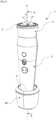
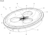
- Said massage head 2 is advantageously intended to form one of the (two) (opposite) ends of the massage device 1, the latter having in particular a substantially elongated shape, and for example, as illustrated in Figures 1 to 4 , a generally substantially cylindrical shape, the massage head 2 then forming an end portion of the cylindrical shape.
- the massage apparatus 1 has a lower end 4 and an upper end 5 opposite the lower end 4.
- the upper end 5 is preferably formed by said massage head 2.
- the lower end 4 of the apparatus 1 is preferably part of the main body 3, and may comprise an electrical receiving means (such as a female electrical plug) intended to receive an electrical supply means (such as a male electrical plug), for supplying said main body 3 with electricity, so as to produce, at the massage head 2, mechanical work allowing the massage.
- the lower end 4 is designed to be removably (or dismountably or temporarily) connected to a base 30. More particularly, the lower end 4 is designed to be inserted into said base 30.
- the latter is preferably designed to provide a dual function: on the one hand, maintaining the massage device 1 in a stable vertical (or slightly oblique) position, and on the other hand, charging the latter with energy, in this case electrical energy.
- the base 30 comprises the male electrical plug designed to cooperate with the female electrical plug of the main body 3.
- the massage device 1 comprises said base 30.
- said massage head 2 is preferably designed and configured to be connected to said main body 3 in a removable manner. (or temporary).
- Said main body 3 preferably has a substantially elongated shape having two opposite ends 4, 6.
- the massage head 2 is preferably designed to be removably attached to one of the two ends 4, 6 of the main body 3.
- the massage head 2 is advantageously fixed to the main body 3 substantially in the extension of the latter.
- Said main body 3 has for example a substantially cylindrical general shape.
- One of the two opposite ends of the main body 3 is for example formed by said lower end 4, while the other end of said main body 3 is formed by a connection end 6, which is intended to be secured to the massage head 2.
- the massage head 2 comprises a first fixing means
- the main body 3 comprises a second fixing means complementary to the first fixing means.
- the second fixing means is for example positioned substantially at or in the vicinity of said connection end 6.
- Said first and second fixing means are preferably designed to cooperate mechanically in order to reversibly secure said massage head 2 and said main body 3.
- Such fixing means are known as such and will not be detailed here further.
- the massage device 1 is in particular portable, that is to say that it is for example designed to be handled with only one hand by the user, without requiring any other mechanical support, and/or that it can be easily transported from one place to another by the user without assistance or a particular vehicle.
- the massage device 1 for example, has dimensions and weight that are sufficiently small to be able to be stored in a bathroom drawer, or carried in a backpack or even a handbag.
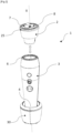
- the massage head 2 comprises at least one working head 7, which comprises massage means 8 which each have a working surface 9 (respective) intended to come into contact with the skin in order to massage it.
- each massage means 8 has, in particular at its working surface 9, an external appearance of a half-ball intended to be rotated when it is placed in contact with the skin in order to massage the latter.
- Said massage means 8 are preferably distinct and positioned at a distance from each other. They may also be substantially similar in shape and function.
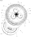
- the working head 7 comprises, in the embodiments illustrated in the figures, three massage means 8 (one of which is hidden from the figure 9 ), but it could alternatively have only two, or more than three, for example four or five.
- each massage means 8 is preferably formed by the external surface of said massage means 8, that is to say for example a surface exposed to the open air and not integrated/hidden within the rest of the massage head 2.
- the working head 7 is in particular represented surrounded by virtual dotted lines at figure 9 .
- the massage head 2 further comprises at least one operating member 10 designed and configured to actuate said working head 7 in rotation around a primary rotation axis X.
- Said working head 7 is advantageously mounted to rotate relative to said main body 3, along the primary rotation axis X, and is intended to be rotated by said operating member 10.
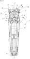
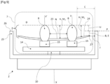
- the primary rotation axis X is substantially inscribed in the section plane AA.
- the primary rotation axis X is illustrated, in particular in the figures except in the figure 3 , as vertical, but it can of course take all possible orientations necessary for massaging the user's skin, and in particular for massaging the user's facial skin.
- the massage device 1 is considered to be positioned vertically, with the massage head 2 at the top (and therefore facing upwards), the primary rotation axis X therefore being, as previously described, vertical, but the device 1 and the massage head 2 can of course take all possible orientations necessary for massaging the user's skin, and in particular for massaging the user's facial skin. the user.
- the height or altitude of an element is preferably considered according to the above convention.
- said working head 7 comprises all the elements of the massage head 2 designed and configured to be rotated, relative to at least said main body 3, along said primary rotation axis X.
- the latter advantageously defines a longitudinal direction of the massage device 1 and/or of the main body 3.
- the main body 3 thus advantageously has a longitudinal extension direction which is preferably coincident with the primary rotation axis X (or at least parallel to the latter).
- the main body 3 comprises for example an output shaft 11 and an electric motor 16 driving said output shaft 11.
- the output shaft 11 is designed to be rotated for example along the primary rotation axis X.
- the operating member 10 comprises for example at least one operating shaft 12 comprising a housing 13 for receiving the output shaft 11, thus making it possible to rotate said working head 7 around said primary rotation axis X as indicated above, when the massage head 2 is attached, removably or not, to said main body 3.
- the main body 3 may comprise, to power the motor, an electric battery and/or the electrical receiving means mentioned above.
- the possible electric battery makes it possible to give a certain autonomy to the massage device 1 (thus improving the portable nature of the latter), and can for example be designed to be recharged with electricity by the electrical power supply means mentioned above, thanks to said base 30.
- Said working head 7 preferably extends substantially around a portion of said primary rotation axis X.
- the rotation of said working head 7 i.e. its rotational actuation by said electric motor
- said working head 7 comprises at least one support assembly 14 carrying said massage means 8.
- said support assembly 14 is integral with the shaft of maneuver 12, or the maneuver shaft 12 is part of said support assembly 14.
- said maneuvering member 10 is preferably designed and configured to actuate said support assembly 14 in rotation.
- the rotational actuation of the working head 7 preferably involves an “ active ” rotation of the working head 7, i.e. the production of automatic mechanical work dedicated to massaging the skin, in particular that of the face.
- This automatic work is therefore advantageously produced using a motor actuation and not in a “ passive ” manner such as a back-and-forth movement performed manually by the user.
- each massage means 8 can be actuated in rotation about a respective secondary rotation axis Y, Y', Y".
- each massage means 8 advantageously extends around a portion of the secondary rotation axis Y, Y', Y" considered and is designed to be rotated about this axis.
- the rotation of the massage means 8 i.e. its rotational actuation, for example by the electric motor
- the rotational actuation of each massage means 8 mentioned above implies an " active " rotation of the working means 8, similar to what was described above for the working head 7.
- each massage means 8 comprises at least, for example at its working surface 9, a respective substantially convex portion intended to come into contact with the skin.
- Said substantially convex portion has for example a half-ball shape as mentioned above.
- Each substantially convex portion is therefore preferably intended to be actuated in rotation along its axis of rotation Y, Y', Y" respective.
- the massage head 2 further comprises operating means 15 adapted to move each massage means 8 in rotation along the respective secondary axis of rotation Y, Y', Y" (preferably as mentioned above).
- Said secondary axes of rotation Y, Y', Y" are preferably substantially parallel and not coincident.
- Each secondary rotation axis Y, Y', Y" is preferably substantially parallel to said primary rotation axis X.
- Each secondary rotation axis Y, Y', Y" is also advantageously located at a distance from said primary rotation axis X, and is therefore in particular not coincident with the latter.
- the operating means 15 are optionally adapted to cooperate with the drive member 10 so as to transmit and transform the rotational movement of the electric motor 16 into a rotational movement of the massage means 8, for example using a gear train.
- the operating means 15 are preferably adapted to provide a movement to the (for example three) massage means 8, that is to say a secondary rotational movement of the massage means 8 each around its respective secondary rotation axis Y, Y', Y".
- each massage means 8 advantageously rotates on itself along its respective secondary rotation axis Y, Y', Y".
- This secondary rotational movement of the massage means 8 is advantageously a linked movement, that is to say that all the massage means 8 rotate together, and preferably at the same speed (each around its respective secondary rotation axis Y, Y', Y").
- the massage head 2 is preferably adapted to impart a planetary movement to the (for example three) massage means 8, that is to say a main rotational movement of the massage means 8 around the primary rotation axis X associated with a secondary rotational movement of each of the massage means 8 around the secondary rotation axis Y, Y', Y" considered.
- a planetary movement makes it possible in particular to reproduce the kneading or shearing gesture that a professional masseur could make with his fingers.
- Such a gesture (and therefore movement of the massage means 8) massage 8) is particularly well suited for treating the cheekbones, cheeks, the oval of the face (the area between the jaws, the chin), or even the neck.
- said operating means 15 are advantageously designed to rotate (secondary, therefore) the massage means 8 along the secondary rotation axes Y, Y', Y" relative to the support assembly 14, which preferably only performs the rotation (main, therefore) along the primary rotation axis X, thanks in particular to said operating member 10.
- the operating means 15 are advantageously part of the working head 7, and can be carried by the support assembly 14.
- the main rotational movement (along the primary rotation axis X) of the massage means 8 is advantageously a linked movement, that is to say that all the massage means 8 rotate together, and preferably at the same speed (around the primary rotation axis X).
- said working head 7 further comprises an outer surface 17 from which each massage means 8 emerges. Furthermore, each massage means 8 rises, from said outer surface 17, over a respective massage height H of between 5 mm and 9 mm.
- the working surface 9 of each massage means 8 extends, from the outer surface 17, over said massage height H which is at least equal to 5 mm, and at most equal to 9 mm.
- each massage height H is between 6 and 8 mm, for example approximately equal to 7 mm (+/- 0.3 mm).
- each massage height H can be defined as the shortest distance between a point on the outer surface 17 and a point at the same height as the massage means 8 considered, said points being projected onto a common axis, preferably onto the primary rotation axis X.
- the massage height H is for example measured in a direction parallel to the primary rotation axis X.
- the massage height H is on the one hand large enough to allow the skin to be massaged, and therefore slightly deformed, by the massage means 8, and on the other hand small enough to limit or eliminate the risks of pinching the skin thus massaged.
- the massage height H as defined by the invention is a remarkable compromise between massage effectiveness and absence of pain for the user.
- the massage heights H of the different massage means 8 are, of course, measured in the vicinity of the latter.
- the outer surface 17 is part of the working head 7, the latter is preferably designed so that said outer surface 17 is rotated along the primary rotation axis X by means of said operating member 10.
- said massage means 8 are advantageously positioned substantially below a distal plane D substantially perpendicular to said primary rotation axis X (and, in the illustrated embodiments, also perpendicular to each of the secondary rotation axes Y, Y', Y").
- the working surface 9 of each massage means 8 extends from the outer surface 17 to at least one respective free end point 18, the latter preferably being substantially opposite the outer surface 17 relative to the remainder of the working surface 9.
- Said free end point 18 is preferably the point of the massage surface 9 furthest from the outer surface 17, i.e. the highest point of the massage means 8.
- the massage height H may be defined as the distance between a point of the outer surface 17 and the free end point 18, said points being projected onto a common axis, preferably onto the primary rotation axis X. Said massage means 8 therefore emerges from said outer surface 17 to said free end point 18.
- said free end points 18 are inscribed in the (same) distal plane D, said massage means 8 advantageously having substantially similar massage heights H.
- the highest free end point 18, i.e. in particular the free end point 18 furthest from the outer surface 17 or the highest in a direction parallel to the primary rotation axis X is inscribed in said distal plane D, and the other free end points 18 are positioned below said distal plane D.
- the massage means 8 which comprises the highest free end point 18 is preferably the largest of the massage means 8 and/or the one with the greatest massage height H. Said massage means 8 are therefore all substantially below said distal plane D, with the possible exception of the free end point 18 of at least one massage means 8, said free end point 18 being inscribed in said distal plane D. Each free end point 18 is preferably intended to be turned towards the skin, then to come into contact with the latter when said massage head 2 is implemented.
- Said massage height H can for example be defined more precisely as the distance, measured perpendicular to said distal plane D, between (a point of) the outer surface 17 and the distal plane D.
- the massage height H can therefore vary substantially over the entire outer surface 17, in particular if the latter is not flat, as will be detailed later.
- the massage height H is preferably between 5 mm and 9 mm regardless of the point of the outer surface 17 considered.
- the working surface 9 of each massage means 8 extends in projection from the outer surface 17 to the free end point 18 of said massage means 8.
- said working head 7 comprises a monolithic plate 19 attached forming said external surface 17.
- This monolithic plate 19 is illustrated in the figures, and a particular embodiment of this plate 19 is illustrated alone in the figure. figure 8
- said plate 19 is carried by said support assembly 14.
- said massage head 2 is preferably designed so that said plate 19 is rotated along the primary rotation axis X by means of said operating member 10.
- the massage means 8 pass through said monolithic plate 19. Said massage means 8 are therefore preferably mounted to rotate, each along its respective secondary axis of rotation Y, Y', Y", relative to the monolithic plate 19.
- the latter advantageously forms a part attached to one end of the massage head 2 making it possible to significantly reduce, or even eliminate, the risk of unusual, or even painful, pinching of the skin being massaged by said massage head 2 by filling any gap that is too large. where skin folds could be lodged.
- the monolithic plate 19 also makes it easier to modulate the massage height H, which can of course vary over the extent of said plate 19.
- the monolithic plate 19 is therefore preferably intended to have a first face turned towards and preferably in contact with the skin to be massaged, as well as a second face opposite the first face and turned for example towards the inside of the working head 7, the support assembly 14 and/or the main body 3. Said first face advantageously forms said outer surface 17.
- the plate 19 is monolithic, and is therefore advantageously formed from a single substantially rigid piece, having a certain cohesion, and which preferably cannot be divided into several parts in normal use, said plate 19 therefore advantageously not being disassemblable into several separate parts.
- the monolithic tray 19 is formed of several parts secured together so as to obtain a rigid final part, which has a cohesion, a solidity similar or almost similar to that of a single single part.
- the monolithic tray 19 is preferably made of plastic or metal. According to a particular example, it is molded in a single block. According to another particular example, the monolithic tray 19 can be formed by several (in particular two) plastic or metal parts welded together.
- Said outer surface 17 has, according to a particular embodiment illustrated in the figures, a generally circular shape, which advantageously has a diameter of between 30 mm and 60 mm, preferably between 35 mm and 55 mm, for example approximately equal to 44 mm (+/- 3 mm), the size of this diameter being particularly suitable for massaging the skin of the face.
- said monolithic plate 19 has, according to the same particular embodiment illustrated in the figures, a generally circular shape, which comprises in particular a disk, substantially forming said outer surface 17, and possibly an insertion part 20 extending substantially in projection from said disk opposite the outer surface 17 and intended to be inserted within other elements of said massage head 2.
- the insertion part therefore advantageously extends from said second face, downwards.
- the insertion part 20 extends for example parallel to the primary rotation axis X and/or perpendicular to said disk. It is preferably designed to secure said monolithic plate 19 to the rest of the working head 7.
- the disk advantageously has a generally flat appearance, even if it can be provided with one or more slight curvatures, concavity(ies) and/or convexity(ies), having a large radius of curvature, for example between 100 mm and 250 mm. For example, the disk is unambiguously distinguished from a portion of a sphere.
- Said monolithic plate 19 advantageously has a plurality of passage orifices 21.
- said monolithic plate 19 comprises as many passage orifices 21 as there are massage means 8.
- Each passage orifice 21 is designed to allow one of the massage means 8 to pass through said plate 19 and thus to rise above said outer surface 17.
- Said massage means 8 therefore rise higher than the outer surface 17, but preferably not directly above the latter.
- Said passage orifices 21 are preferably made in said disk.
- the massage means 8 and the outer surface 17 are not secured together, and there is a very small gap (less than 2 mm, preferably between 0.2 mm and 1.2 mm), perpendicular to said primary rotation axis X or to said secondary rotation axis Y, Y', Y" considered, between each massage means 8 and the outer surface 17 (or more precisely the monolithic plate 19).
- the massage head 2 is designed so that this gap is provided between each massage means 8 and an inner edge 22 of the passage orifice 21 in which said massage means 8 is inserted. This gap in particular allows the massage means 8 to be rotated about its respective secondary rotation axis Y, Y', Y", but is small enough to avoid undesirable pinching of the skin.
- Each massage means 8 preferably has a dimension (also called maximum dimension M, illustrated in figure 6 ) measured perpendicular to the secondary axis of rotation Y, Y', Y" of the massage means 8, said dimension (maximum M) being between 7 mm and 12 mm, more preferably between 8 mm and 11 mm, for example equal to approximately 9.5 mm (+/- 0.5 mm).
- This dimension (maximum M) is for example measured at the level where the massage means 8 emerges from the outer surface 17, that is to say advantageously the lowest (visible) altitude of said massage means 8.
- each passage orifice 21 advantageously has a diameter complementary to the shape of the massage means 8 (in particular its maximum dimension M) inserted in said passage orifice 21, said complementary diameter preferably being between 7.5 mm and 12.5 mm, more preferably between 8.5 mm and 11.5 mm, for example equal to approximately 10 mm (+/- 0.5 mm).
- said outer surface 17 comprises, between said massage means 8, a first surface portion 23.
- Said first surface portion 23 is preferably positioned at a distance (optionally called first massage distance M 1 ) of between 5 mm and 9 mm from said distal plane D, more preferably between 6 mm and 8 mm.
- Said distance (massage distance M 1 ) is preferably calculated in a direction parallel to said primary axis of rotation X.
- first massage distance M 1 advantageously constitutes, at said first surface portion 23, said massage height H.
- said first surface portion 23 extends substantially between said massage means 8, and constitutes for example the outer surface portion 17 highlighted between (virtual) dotted lines at figures 3 And 8 .
- the particular position of the first surface portion 23 makes it possible in particular to avoid excessive and/or painful pinching of the skin massaged between said massage means 8, while ensuring good massage efficiency, since the skin can be drawn between said massage means 8 but in a limited manner (and in particular only over the first massage distance M 1 of between 5 mm and 9 mm).
- the risk of painful pinching of the skin between several massage means 8 is drastically reduced or even eliminated, which in particular makes it possible to use the massage head 2 to massage any type of skin (i.e. in particular the skin of any person's face, or any area of the face, whether the skin is flaccid, thin, firm, supple, etc.).
- said first surface portion 23 has at least one respective line portion (called an interval) that is as short as possible, each point of said shortest possible line portion (interval) being positioned at a lower distance of between 5 mm and 9 mm from said distal plane D, and more preferably of between 6 mm and 8 mm, said distance constituting in substance said first massage distance M 1 .
- the expression as short as possible refers to the shortest straight line distance L that separates the first surface portion 23 from the plane D.
- Said interval line is for example illustrated by the line of the first surface 23 located below (in a direction parallel to the primary rotation axis X) the dotted lines illustrating the interval distance denoted N at the figure 3 , and can therefore be significantly curved (see concavity described below).
- the working head 7 comprises three massage means 8
- the latter are advantageously arranged so as to form (overall) the vertices of an equilateral (virtual) triangle, as shown in the figures, and the first surface portion 23 has a globally triangular shape with rounded edges, as highlighted by dotted lines in the figures. figures 3 And 8 .
- these advantageously each comprise at least one respective free end point 18 as mentioned above, and said three free end points 18 are preferably arranged so as to form the vertices of an equilateral (virtual) triangle.
- the equilateral triangle preferably comprises a (virtual) center through which said primary axis of rotation X passes.
- the massage head 2 comprises a support crown 25 intended to come against the skin and defining, on the one hand, a support surface 26 falling within a support plane P and, on the other hand, a work zone Z. located inside the support ring 25 and in which said outer surface 17 is located, at least part of the working surface 9 of each massage means 8 extending projecting from the support plane P.
- said support ring 25 is distinct from said working head 7 so that when the latter is rotated by said operating member 10, said support ring 25 remains fixed.
- each massage means 8 extending in projection from the support plane P is in substance formed by the external surface of the massage means 8 comprised between the support plane P and the distal plane D, as illustrated in particular in FIG. figure 6 .
- This external surface of the massage means 8 comprised between said support planes P and distal D forms in particular a projection protruding from the support ring 25, going from the support plane P to the free end point 18.
- the support ring 25 allows the user to better control the massage of the skin, by placing the support surface 26 of the support ring 25 against the skin.
- the support ring 25 is preferably fixed and therefore devoid of electrically actuated rotation, and remains immobile relative to the main body 3, while the working head 7 is rotated.
- Such a configuration allows a particularly effective and controlled massage of each area of the skin within said working area Z.
- the working area Z preferably comprises the space comprised between the external surface 17 and the distal plane D.
- the support ring 25 makes it possible to avoid involuntary movement of the massage head 2 along the user's skin.
- This involuntary movement can be caused on the one hand by the rotation of the external surface 17 along the primary rotation axis X and on the other hand by the movement, advantageously planetary (or in any case rotary), of the massage means 8 (which advantageously perform a main rotation along the primary rotation axis X and a secondary rotation along their secondary rotation axes Y, Y', Y')' respective.
- the support crown 25 generally has the shape of a fixed ring surrounding the monolithic plate 19, as illustrated in the figures with the exception of the figures 7 And 8 . In the figure 7 , the support crown 25 and the other fixed elements of the massage head 2 have been removed to leave only the working head 7 visible (which rotates around the primary rotation axis X).
- said outer surface 17 comprises, around said first surface portion 23, a second surface portion 24 positioned at a distance (optionally called second massage distance M 2 ) of between 5 mm and 9 mm from said distal plane D, more preferably of between 5.5 mm and 7.5 mm.
- Said distance (massage distance M 2 ) is preferably calculated in a direction parallel to said primary axis of rotation X.
- the distance defined above, optionally called second massage distance M 2 advantageously constitutes, at said second surface portion 24, said massage height H.
- said second surface portion 24 extends substantially around said first surface portion 23, and also advantageously surrounds the plurality of massage means 8.
- Said second surface portion 24 constitutes for example the outer surface part 17 outside the (virtual) dotted lines of the figures 3 And 8 .
- the second surface portion 24 has an overall crown shape, and more precisely that of a region comprised between a circle (the free outer edge 27 described below) and a central triangular-shaped zone with rounded edges (the first surface portion 23).
- the particular position of said second surface portion 24 makes it possible in particular to avoid excessive and/or painful pinching of the skin massaged between a massage means 8 and another element of the massage head 2 such as the support crown 25, while ensuring good massage efficiency, since the skin can be drawn between one of the massage means 8 and the support crown 25 but in a limited manner (and in particular only over the second massage distance M 2 comprised between 5 mm and 9 mm).
- the risk of painful pinching of the skin between one of the massage means 8 and the support ring 25 is drastically reduced or even eliminated, which in particular makes it possible to use the massage head 2 to massage any type of skin.
- Said first and second surface portions 23, 24 are preferably integral, in the extension of one another, and advantageously made of one material, their purely virtual and functional separation being only shown in the figures 3 And 8 by dotted lines themselves virtual.
- each massage means 8 is located at a distance (optionally called crown distance C) greater than or equal to 6 mm from said support crown 25, said distance (of crown C) being more preferably between 7 mm and 12 mm, for example approximately equal to 9.5 mm (+/- 0.6 mm).
- This distance (of crown C) is in particular measured in a direction perpendicular to the primary rotation axis X and/or a direction parallel to the support plane P. Such a configuration helps to avoid painful pinching, while ensuring excellent massage efficiency.
- the massage means 8 are arranged, within the massage zone Z, in a regular manner around the primary rotation axis X.
- the secondary rotation axes Y, Y', Y" are substantially parallel to the primary rotation axis X and are therefore distributed angularly in a regular manner around the axis X.
- the secondary rotation axes Y, Y', Y" are preferably all located, perpendicular to the primary rotation axis X, at the same distance (not illustrated) from the primary rotation axis X. This regular arrangement allows an excellent distribution of the massage movement on the area of skin to be massaged.
- said outer surface 17 has at least one respective portion of line (called lateral) L that is as short as possible, each point of said portion of line (lateral) L that is as short as possible being positioned at a distance less than or equal to 4 mm, and preferably between 0.4 mm and 1.4 mm, from said support plane P, the distance being measured parallel to the axis of rotation.
- primary X i.e. vertically as explained above.
- the “shortest possible expression” refers to the shortest distance in a straight line L which separates each massage means 8 and the support ring 5, the line L belonging to the outer surface 17.
- Said portion of line (lateral) L advantageously forms part of said second surface portion 24, and is illustrated in particular by a dotted line at figure 3 .
- This configuration makes it possible to give a significant anti-pinch character to the outer surface 17.
- said second surface portion 24 is positioned, preferably at all points, at a distance less than or equal to 4 mm, and preferably between 0.4 mm and 1.4 mm, from said support plane P, preferably in a direction parallel to the primary rotation axis X.
- the risk of seeing an undesirable and painful pinching occur between the support ring 25 and one of the massage means 8 is particularly reduced.
- said outer surface 17 has a substantially circular free outer edge 27.
- said free outer edge 27 delimits the second surface portion 24, the latter therefore extending between said free outer edge 27 and said first surface portion 23.
- Said free outer edge 27 is preferably surrounded by the support ring 25, each part of the free outer edge 27 facing a part of the support ring 25.
- said free outer edge 27 is positioned, in a direction parallel to said primary axis of rotation X, at a distance (possibly called edge distance B, illustrated in figure 6 ) less than or equal to 2 mm, and preferably between 0.6 mm and 1.8 mm, of said support plane P.
- said external surface 17 is positioned, advantageously at all points, in a direction parallel to said primary axis of rotation X, at a distance (possibly called support/surface distance E, illustrated in figure 6 ) less than or equal to 2 mm, and preferably between 0.4 mm and 1.8 mm, of said support plane P.
- said distance (support/surface E) is formed by the edge distance B.
- the figure 6 illustrates the minimum support/surface distance E for the outer surface 17 considered.
- the support/surface distance E and/or the massage height H is/are for example maximum at the center of the outer surface 17, in particular when the latter has a concave zone 28 as described below.
- the support/surface distance E is, preferably at all points of the second surface portion 24, advantageously between 0.4 mm and 1.4 mm.
- said free outer edge 27 defines, perpendicular to said primary rotation axis X, a clearance J with said support ring 25 which is less than or equal to 2 mm, preferably between 0.2 mm and 1.2 mm.
- the clearance J is advantageously measured along a distance substantially parallel to said support plane P.
- said outer surface 17 is positioned at a certain distance, represented by the clearance J, from said support ring 25, said distance (i.e. said clearance J) being less than or equal to 2 mm, preferably between 0.2 mm and 1.2 mm, and measured horizontally when the primary rotation axis X is vertical.
- Such a configuration prevents the skin from becoming trapped between the support ring 25 and the outer surface 17, and therefore considerably reduces, or even eliminates, the risk of painful pinching.
- the edge distance B (or the support/surface distance E) and the clearance J both prevent unwanted pinching of the skin and allow proper massage of the skin.
- the clearance J is preferably found all around the free outer edge 27.
- the shortest distance (possibly called interval distance N, illustrated in figures 3 And 5 ) between the surface of two massage means 8 is between 5 mm and 7.8 mm, preferably about 7 mm (+/- 0.3 mm).
- Such a configuration is also optimal for avoiding painful pinching of the massaged skin between the massage means 8 while effectively massaging the latter (i.e. enough skin is allowed to "fit" between said massage means 8).
- the outer surface 17 comprises a concave zone 28 having a concavity facing outwards, that is to say that advantageously the concavity is intended to be facing the skin when massaging the latter. More advantageously, the concavity is intended to be at least partly in contact with the skin when massaging the latter.
- at least one (and advantageously all) of the massage means 8 is (are) positioned in said concave zone 28.
- Such a configuration is illustrated in the embodiments of the figures, and makes it possible to optimize the massage efficiency.
- this configuration makes it possible to substantially increase, by a simple-to-implement construction detail of the outer surface 17 and/or the monolithic plate 19, the quantity of skin that can be “ driven ” within the working zone Z, compared with an outer surface that would be flat or only convex.
- the concave zone 28 substantially forms a central part of the outer surface 17 (and therefore of the monolithic plate 19).
- said concavity has a radius of curvature of between 100 mm and 250 mm, more preferably of between 140 mm and 200 mm, for example approximately equal to 170 mm (+/- 10 mm).
- the first surface portion 23 advantageously comprises at least a portion of said concave zone 28.
- said concave zone 28 forms the entirety of said first surface portion 23 and a portion of the second surface portion 24, as illustrated in Figures 1 to 8
- the concave zone 28 is preferably positioned at least partly between said massage means 8.
- the outer surface 17 further comprises a convex lateral zone 29, said second surface portion 24 advantageously comprising said convex lateral zone 29.
- said convex lateral zone 29 surrounds said concave zone 28, and is located between said free outer edge 27 and said first surface portion 23, which are therefore located at a lower altitude than that of the convex lateral zone 29.
- Such a configuration provides excellent mechanical resistance to the monolithic plate 19, as well as a increased or at least maintained massage, and incidentally a certain aesthetic appeal to said massage head 2.
- This configuration also makes it possible to avoid creating an edge that is too pronounced and potentially injurious to the user, for example at the free outer edge 27. Such an edge is notably visible at the figure 9 , although the embodiment illustrated by it is purely schematic.
- the distal plane D and the support plane P are not merged, and are positioned relative to each other, in a direction parallel to the primary rotation axis X, at a distal/support distance U advantageously between 4 mm and 7 mm, more preferably between 4.5 mm and 6.5 mm.
- the distal plane D is preferably above the support plane P.
- the elements mentioned of the massage head 2 and of the massage device 1 have a certain rigidity, i.e. a specific mechanical strength, and can be made of any suitable material (plastic, metal in particular).
- the external surface 17 makes it possible to prevent undesirable elements, such as dirt, from entering the internal mechanism of the massage head 2 from the outside.
- undesirable elements may in particular be, during the use of the device 1 and the massage head 2, dead skin, dust, cream applied to the skin, or during the storage of the device 1 and the massage head 2 (therefore not in use), dust, a wire of an electrical device, a portion of a small body care tool (nail clippers for example), etc.
- the device 1 and the massage head 2 can thus be used on skin previously coated with cream to improve the effectiveness of the massage.
- the clearance J makes it possible, for example, to significantly reduce the risk of undesirable elements getting between the support ring 25 and the surface external surface 17 (more precisely its free external edge 27), and damage or clog the working head 7, in particular the mechanisms present under the external surface 17, such as for example the operating means 15 or the operating member 10, thus reducing the duration of use of the device 1 and the massage head 2.
- the monolithic plate 19, in particular, makes it possible to protect the interior of the massage head 2.
- the face is an area that is extremely sensitive to painful pinching by mechanical massage organs, particularly due to the prominent nature of certain portions of the face (cheekbones, etc.), the amount of skin present in certain areas (cheeks, neck, for example), and the condition of this skin depending on the areas and people being massaged.
- the device 1 and the massage head 2 of the invention are particularly suitable for effective massage without unpleasant or painful pinching of the facial skin of a user, particularly a non-professional user, regardless of the user's skin type (for example, regardless of the presence of wrinkles, flaccidity, fineness, or elasticity of the skin).
Landscapes
- Health & Medical Sciences (AREA)
- Epidemiology (AREA)
- Pain & Pain Management (AREA)
- Physical Education & Sports Medicine (AREA)
- Rehabilitation Therapy (AREA)
- Life Sciences & Earth Sciences (AREA)
- Animal Behavior & Ethology (AREA)
- General Health & Medical Sciences (AREA)
- Public Health (AREA)
- Veterinary Medicine (AREA)
- Dermatology (AREA)
- Massaging Devices (AREA)
Claims (15)
- Massagekopf (2) für ein mechanisches Hautmassagegerät (1), wobei das Gerät (1) einen Hauptkörper (3) umfasst, der einen manuellen Griffbereich bildet und mit dem der Massagekopf (2) verbunden werden soll, wobei der Massagekopf (2) mindestens Folgendes umfasst:- einen Arbeitskopf (7), der Massagemittel (8) umfasst, von denen jedes eine Arbeitsfläche (9) besitzt, die dazu bestimmt ist, mit der Haut in Kontakt zu kommen, um sie zu massieren, wobei der Arbeitskopf (7) derart konfiguriert ist, dass jedes Massagemittel (8) um eine jeweilige sekundäre Drehachse (Y, Y', Y") drehangetrieben werden kann, und- ein Betätigungselement (10), das dazu ausgelegt und konfiguriert ist, den Arbeitskopf (7) um eine primäre Drehachse (X) drehanzutreiben,wobei der Arbeitskopf (7) ferner eine äußere Oberfläche (17) umfasst, aus der jedes Massagemittel (8) austritt,dadurch gekennzeichnet, dass jedes Massagemittel (8) von der äußeren Oberfläche (17) auf eine jeweilige Massagehöhe (H) zwischen 5 mm und 9 mm ansteigt.
- Massagekopf (2) nach dem vorhergehenden Anspruch, dadurch gekennzeichnet, dass jede Massagehöhe (H) zwischen 6 mm und 8 mm, beispielsweise ungefähr gleich 7 mm (+/-0,3 mm), beträgt.
- Massagekopf (2) nach Anspruch 1 oder 2, dadurch gekennzeichnet, dass die Massagemittel (8) unterhalb einer distalen Ebene (D) positioniert sind, die im Wesentlichen senkrecht zur primären Drehachse (X) ist, wobei die äußere Oberfläche (17) zwischen den Massagemitteln (8) einen ersten Oberflächenabschnitt (23) umfasst, der in einem Abstand zwischen 5 mm und 9 mm von der distalen Ebene (D) positioniert ist.
- Massagekopf (2) nach dem vorhergehenden Anspruch, dadurch gekennzeichnet, dass die äußere Oberfläche (17) um den ersten Oberflächenabschnitt (23) herum einen zweiten Oberflächenabschnitt (24) umfasst, der in einem Abstand zwischen 5 mm und 9 mm von der distalen Ebene (D) positioniert ist.
- Massagekopf (2) nach einem der vorhergehenden Ansprüche, wobei er einen Lagerring (25) umfasst, der dazu bestimmt ist, an die Haut zu kommen, und einerseits eine Auflagefläche (26) innerhalb einer Auflageebene (P) und andererseits einen Arbeitsbereich (Z) definiert, der sich innerhalb des Lagerrings (25) befindet und in dem sich die äußere Oberfläche (17) befindet, wobei sich ein Teil mindestens der Arbeitsfläche (9) jedes Massagemittels (8) aus der Auflageebene (P) vorspringend erstreckt, wobei der Lagerring (25) vom Arbeitskopf (7) getrennt ist, so dass, wenn letzterer durch das Betätigungselement (10) gedreht wird, der Lagerring (25) stationär bleibt.
- Massagekopf (2) nach dem vorhergehenden Anspruch, dadurch gekennzeichnet, dass die äußere Oberfläche (17) einen im Wesentlichen kreisförmigen freien Außenrand (27) aufweist, der in einer parallelen Richtung zur Hauptdrehachse (X) in einem Abstand von weniger als oder gleich 2 mm, und vorzugsweise zwischen 0,6 mm und 1,8 mm, von der Auflageebene (P) positioniert ist.
- Massagekopf (2) nach Anspruch 5 oder 6, dadurch gekennzeichnet, dass die äußere Oberfläche (17) einen im Wesentlichen kreisförmigen freien Außenrand (27) aufweist, der senkrecht zur primären Drehachse (X) ein Spiel (J) mit dem Lagerring (25) definiert, das kleiner oder gleich 2 mm ist und vorzugsweise zwischen 0,2 mm und 1,2 mm beträgt.
- Massagekopf (2) nach einem der Ansprüche 5 bis 7, dadurch gekennzeichnet, dass zwischen jedem Massagemittel (8) und dem Lagerring (25) die äußere Oberfläche (17) jeweils mindestens einen Linienabschnitt (L) aufweist, der möglichst kurz ist, wobei jeder Punkt des möglichst kurzen Linienabschnitts (L) in einem Abstand von weniger als oder gleich 4 mm, und vorzugsweise zwischen 0,4 mm und 1,4 mm, von der Auflageebene (P) positioniert ist.
- Massagekopf (2) nach einem der vorhergehenden Ansprüche, dadurch gekennzeichnet, dass der kürzeste Abstand zwischen der Oberfläche zweier Massagemittel (8) zwischen 5 mm und 7,8 mm, vorzugsweise etwa 7 mm (+/ 0,3 mm), beträgt.
- Massagekopf (2) nach einem der vorhergehenden Ansprüche, dadurch gekennzeichnet, dass die äußere Oberfläche (17) einen konkaven Bereich (28) umfasst, der eine nach außen gerichtete Konkavität aufweist, wobei mindestens eines der Massagemittel (8) in dem konkaven Bereich (28) positioniert ist.
- Massagekopf (2) nach dem vorhergehenden Anspruch, dadurch gekennzeichnet, dass die Konkavität einen Krümmungsradius zwischen 100 mm und 250 mm aufweist.
- Massagekopf (2) nach einem der vorhergehenden Ansprüche, dadurch gekennzeichnet, dass jedes Massagemittel (8) mindestens einen jeweiligen im Wesentlichen konvexen Abschnitt umfasst, der dazu bestimmt ist, mit der Haut in Kontakt zu kommen.
- Massagekopf (2) nach einem der vorhergehenden Ansprüche, dadurch gekennzeichnet, dass der Arbeitskopf (7) eine befestigte monolithische Platte (19) umfasst, die die äußere Oberfläche (17) bildet, und dass die Massagemittel (8) durch die monolithische Platte (19) verlaufen.
- Mechanisches Hautmassagegerät (1), das einen Hauptkörper (3), der einen manuellen Griffbereich bildet, und einen Massagekopf (2) umfasst, der dazu bestimmt ist, mit dem Hauptkörper (3) verbunden zu werden, wobei der Massagekopf (2) einem der vorhergehenden Ansprüche entspricht.
- Massagegerät (1) nach dem vorhergehenden Anspruch, dadurch gekennzeichnet, dass der Massagekopf (2) dazu ausgelegt und konfiguriert ist, abnehmbar mit dem Hauptkörper (3) verbunden zu werden.
Applications Claiming Priority (2)
| Application Number | Priority Date | Filing Date | Title |
|---|---|---|---|
| FR2008509A FR3113373B1 (fr) | 2020-08-14 | 2020-08-14 | Tete et appareil de massage anti-pincement |
| PCT/EP2021/072316 WO2022034111A1 (fr) | 2020-08-14 | 2021-08-10 | Tete et appareil de massage anti-pincement |
Publications (3)
| Publication Number | Publication Date |
|---|---|
| EP4196071A1 EP4196071A1 (de) | 2023-06-21 |
| EP4196071B1 true EP4196071B1 (de) | 2024-11-13 |
| EP4196071C0 EP4196071C0 (de) | 2024-11-13 |
Family
ID=73643033
Family Applications (1)
| Application Number | Title | Priority Date | Filing Date |
|---|---|---|---|
| EP21762407.1A Active EP4196071B1 (de) | 2020-08-14 | 2021-08-10 | Einklemmschutz-massagekopf und vorrichtung |
Country Status (7)
| Country | Link |
|---|---|
| US (1) | US20230301866A1 (de) |
| EP (1) | EP4196071B1 (de) |
| JP (1) | JP2023538026A (de) |
| KR (1) | KR20230051539A (de) |
| CN (1) | CN116133632A (de) |
| FR (1) | FR3113373B1 (de) |
| WO (1) | WO2022034111A1 (de) |
Families Citing this family (1)
| Publication number | Priority date | Publication date | Assignee | Title |
|---|---|---|---|---|
| KR102853366B1 (ko) * | 2025-01-06 | 2025-09-01 | 주식회사 디티플러스 | 고주파 마사지기의 헤드 장치 |
Family Cites Families (17)
| Publication number | Priority date | Publication date | Assignee | Title |
|---|---|---|---|---|
| US5131384A (en) * | 1991-05-23 | 1992-07-21 | Obagi Zein E | Combination applicator/massager |
| US5725483A (en) * | 1994-02-22 | 1998-03-10 | Podolsky; Grigory | Massaging device |
| US6866776B2 (en) * | 2003-03-14 | 2005-03-15 | Wendy Zeller Leason | Heater for massage nodes and massage therapy device including same |
| JP3139966U (ja) * | 2007-05-18 | 2008-03-13 | 修治 ▲高▼橋 | マッサージ器具 |
| US20120121309A1 (en) * | 2010-11-11 | 2012-05-17 | Chuen Chern Co., Ltd. | Cosmetic applicator with vibration device |
| FR2998181B1 (fr) * | 2012-11-19 | 2014-12-26 | Seb Sa | Appareil de traitement de la peau equipe d'un moyen de guidage |
| FR2998168B1 (fr) * | 2012-11-22 | 2023-04-28 | Seb Sa | Appareil de massage equipe de tetes de massage interchangeables |
| FR3012034B1 (fr) * | 2013-10-17 | 2018-09-28 | Seb S.A. | Appareil de massage avec au moins une tete de massage a rotation excentree |
| US9775976B2 (en) * | 2013-12-17 | 2017-10-03 | L'oreal | Skin cleansing apparatus with oscillation motion converter |
| FR3018691B1 (fr) * | 2014-03-21 | 2016-05-06 | Seb Sa | Appareil de soin avec guide de lumiere |
| FR3031450B1 (fr) * | 2015-01-12 | 2020-10-02 | Lpg Systems | Tete de massage et appareil de massage mettant en œuvre une telle tete |
| US10912428B2 (en) * | 2015-02-12 | 2021-02-09 | Visibelle Derma Institute, Inc. | Tip for skin cleansing device |
| FR3040135B1 (fr) * | 2015-08-18 | 2017-09-15 | Seb Sa | Appareil de massage muni d'au moins une composition cosmetique, dermatologique et/ou pharmaceutique |
| US10456321B2 (en) * | 2015-08-25 | 2019-10-29 | John H. Shadduck | Fluid skin treatment systems and methods |
| JP6975178B2 (ja) * | 2016-06-03 | 2021-12-01 | アールツー・テクノロジーズ・インコーポレイテッド | 皮膚治療のための冷却システムおよび方法 |
| JP6621031B2 (ja) * | 2017-01-12 | 2019-12-18 | パナソニックIpマネジメント株式会社 | 美容装置 |
| JP7292964B2 (ja) * | 2018-09-05 | 2023-06-19 | 株式会社 Mtg | 美容器 |
-
2020
- 2020-08-14 FR FR2008509A patent/FR3113373B1/fr active Active
-
2021
- 2021-08-10 CN CN202180055291.2A patent/CN116133632A/zh active Pending
- 2021-08-10 WO PCT/EP2021/072316 patent/WO2022034111A1/fr not_active Ceased
- 2021-08-10 JP JP2023511545A patent/JP2023538026A/ja active Pending
- 2021-08-10 US US18/021,133 patent/US20230301866A1/en active Pending
- 2021-08-10 KR KR1020237008728A patent/KR20230051539A/ko not_active Withdrawn
- 2021-08-10 EP EP21762407.1A patent/EP4196071B1/de active Active
Also Published As
| Publication number | Publication date |
|---|---|
| CN116133632A (zh) | 2023-05-16 |
| JP2023538026A (ja) | 2023-09-06 |
| FR3113373B1 (fr) | 2023-03-03 |
| EP4196071C0 (de) | 2024-11-13 |
| FR3113373A1 (fr) | 2022-02-18 |
| WO2022034111A1 (fr) | 2022-02-17 |
| EP4196071A1 (de) | 2023-06-21 |
| US20230301866A1 (en) | 2023-09-28 |
| KR20230051539A (ko) | 2023-04-18 |
Similar Documents
| Publication | Publication Date | Title |
|---|---|---|
| EP2862554B1 (de) | Massagegerät mit mindestens einem Massagekopf mit exzentrischer Drehung | |
| EP0725602B1 (de) | Zahnbürste mit doppeldrehputzsystem | |
| WO2015055956A1 (fr) | Appareil de massage avec tête de massage equipee de doigt de tapotement | |
| EP1982683A1 (de) | Massageorgan und dieses enthaltende motorisierte Einheit | |
| EP3116419B1 (de) | Mikrodermabrasionsvorrichtung und mikrodermabrasionsverfahren | |
| EP0938270A1 (de) | Epilationsgerät mit drehbahrer rolle ausgerüstet mit einer vorrichtung zur verminderung von schmerzen | |
| EP4196071B1 (de) | Einklemmschutz-massagekopf und vorrichtung | |
| EP2242443B1 (de) | Zahnbürste mit doppeldrehbürstensystem | |
| EP2433520B1 (de) | Epilierer mit abnehmbarem Massagekopf | |
| US8267941B2 (en) | Electrical depilator | |
| FR2947723A1 (fr) | Dispositif de massage. | |
| EP4262671B1 (de) | Massagekopf mit optimiertem antrieb für massagevorrichtung und massagevorrichtung mit solch einem kopf | |
| FR2716369A1 (fr) | Appareil de massage tenu à la main. | |
| EP0666071A1 (de) | Gerät für die Gesichtsmassage | |
| FR3153740A3 (fr) | Tête de massage | |
| FR3151973A1 (fr) | Dispositif électrique de nettoyage et de massage du visage | |
| FR3153742A1 (fr) | Tête de massage | |
| EP4196069A1 (de) | Hautpflegegerät mit verbessertem abnehmbarem massagekopfantrieb | |
| EP3986355B1 (de) | Verbesserter massagekopf für massagevorrichtung und massagevorrichtung mit einem solchen kopf | |
| FR3153741A1 (fr) | Tête de massage | |
| FR3136951A1 (fr) | Tête d'extraction d'impuretés de la peau | |
| WO2025078403A1 (fr) | Tête de massage | |
| FR3136341A1 (fr) | Pinceau d’application de produit cosmétique à manche déformable | |
| FR2900329A1 (fr) | Appareil de massage a elements de massage entraines en rotation par friction | |
| FR3098696A1 (fr) | Rouleau de tete d’epilation pour appareil a epiler, tete d’epilation et appareil a epiler equipes d’un tel rouleau |
Legal Events
| Date | Code | Title | Description |
|---|---|---|---|
| STAA | Information on the status of an ep patent application or granted ep patent |
Free format text: STATUS: UNKNOWN |
|
| STAA | Information on the status of an ep patent application or granted ep patent |
Free format text: STATUS: THE INTERNATIONAL PUBLICATION HAS BEEN MADE |
|
| PUAI | Public reference made under article 153(3) epc to a published international application that has entered the european phase |
Free format text: ORIGINAL CODE: 0009012 |
|
| STAA | Information on the status of an ep patent application or granted ep patent |
Free format text: STATUS: REQUEST FOR EXAMINATION WAS MADE |
|
| 17P | Request for examination filed |
Effective date: 20230308 |
|
| AK | Designated contracting states |
Kind code of ref document: A1 Designated state(s): AL AT BE BG CH CY CZ DE DK EE ES FI FR GB GR HR HU IE IS IT LI LT LU LV MC MK MT NL NO PL PT RO RS SE SI SK SM TR |
|
| DAV | Request for validation of the european patent (deleted) | ||
| DAX | Request for extension of the european patent (deleted) | ||
| GRAP | Despatch of communication of intention to grant a patent |
Free format text: ORIGINAL CODE: EPIDOSNIGR1 |
|
| STAA | Information on the status of an ep patent application or granted ep patent |
Free format text: STATUS: GRANT OF PATENT IS INTENDED |
|
| INTG | Intention to grant announced |
Effective date: 20240607 |
|
| RIN1 | Information on inventor provided before grant (corrected) |
Inventor name: DE LA CHAPELLE, AMBROISE Inventor name: NORMAND, FABIEN Inventor name: MARZIN, VIVIEN Inventor name: DASSONVILLE, YOHAN |
|
| GRAS | Grant fee paid |
Free format text: ORIGINAL CODE: EPIDOSNIGR3 |
|
| GRAA | (expected) grant |
Free format text: ORIGINAL CODE: 0009210 |
|
| STAA | Information on the status of an ep patent application or granted ep patent |
Free format text: STATUS: THE PATENT HAS BEEN GRANTED |
|
| AK | Designated contracting states |
Kind code of ref document: B1 Designated state(s): AL AT BE BG CH CY CZ DE DK EE ES FI FR GB GR HR HU IE IS IT LI LT LU LV MC MK MT NL NO PL PT RO RS SE SI SK SM TR |
|
| REG | Reference to a national code |
Ref country code: GB Ref legal event code: FG4D Free format text: NOT ENGLISH |
|
| REG | Reference to a national code |
Ref country code: CH Ref legal event code: EP |
|
| REG | Reference to a national code |
Ref country code: IE Ref legal event code: FG4D Free format text: LANGUAGE OF EP DOCUMENT: FRENCH |
|
| REG | Reference to a national code |
Ref country code: DE Ref legal event code: R096 Ref document number: 602021021834 Country of ref document: DE |
|
| U01 | Request for unitary effect filed |
Effective date: 20241122 |
|
| U07 | Unitary effect registered |
Designated state(s): AT BE BG DE DK EE FI FR IT LT LU LV MT NL PT RO SE SI Effective date: 20241129 |
|
| PG25 | Lapsed in a contracting state [announced via postgrant information from national office to epo] |
Ref country code: IS Free format text: LAPSE BECAUSE OF FAILURE TO SUBMIT A TRANSLATION OF THE DESCRIPTION OR TO PAY THE FEE WITHIN THE PRESCRIBED TIME-LIMIT Effective date: 20250313 Ref country code: HR Free format text: LAPSE BECAUSE OF FAILURE TO SUBMIT A TRANSLATION OF THE DESCRIPTION OR TO PAY THE FEE WITHIN THE PRESCRIBED TIME-LIMIT Effective date: 20241113 |
|
| PG25 | Lapsed in a contracting state [announced via postgrant information from national office to epo] |
Ref country code: ES Free format text: LAPSE BECAUSE OF FAILURE TO SUBMIT A TRANSLATION OF THE DESCRIPTION OR TO PAY THE FEE WITHIN THE PRESCRIBED TIME-LIMIT Effective date: 20241113 |
|
| PG25 | Lapsed in a contracting state [announced via postgrant information from national office to epo] |
Ref country code: NO Free format text: LAPSE BECAUSE OF FAILURE TO SUBMIT A TRANSLATION OF THE DESCRIPTION OR TO PAY THE FEE WITHIN THE PRESCRIBED TIME-LIMIT Effective date: 20250213 |
|
| PG25 | Lapsed in a contracting state [announced via postgrant information from national office to epo] |
Ref country code: GR Free format text: LAPSE BECAUSE OF FAILURE TO SUBMIT A TRANSLATION OF THE DESCRIPTION OR TO PAY THE FEE WITHIN THE PRESCRIBED TIME-LIMIT Effective date: 20250214 |
|
| PG25 | Lapsed in a contracting state [announced via postgrant information from national office to epo] |
Ref country code: PL Free format text: LAPSE BECAUSE OF FAILURE TO SUBMIT A TRANSLATION OF THE DESCRIPTION OR TO PAY THE FEE WITHIN THE PRESCRIBED TIME-LIMIT Effective date: 20241113 |
|
| PG25 | Lapsed in a contracting state [announced via postgrant information from national office to epo] |
Ref country code: RS Free format text: LAPSE BECAUSE OF FAILURE TO SUBMIT A TRANSLATION OF THE DESCRIPTION OR TO PAY THE FEE WITHIN THE PRESCRIBED TIME-LIMIT Effective date: 20250213 |
|
| PG25 | Lapsed in a contracting state [announced via postgrant information from national office to epo] |
Ref country code: SM Free format text: LAPSE BECAUSE OF FAILURE TO SUBMIT A TRANSLATION OF THE DESCRIPTION OR TO PAY THE FEE WITHIN THE PRESCRIBED TIME-LIMIT Effective date: 20241113 |
|
| PG25 | Lapsed in a contracting state [announced via postgrant information from national office to epo] |
Ref country code: SK Free format text: LAPSE BECAUSE OF FAILURE TO SUBMIT A TRANSLATION OF THE DESCRIPTION OR TO PAY THE FEE WITHIN THE PRESCRIBED TIME-LIMIT Effective date: 20241113 |
|
| PG25 | Lapsed in a contracting state [announced via postgrant information from national office to epo] |
Ref country code: CZ Free format text: LAPSE BECAUSE OF FAILURE TO SUBMIT A TRANSLATION OF THE DESCRIPTION OR TO PAY THE FEE WITHIN THE PRESCRIBED TIME-LIMIT Effective date: 20241113 |
|
| PLBE | No opposition filed within time limit |
Free format text: ORIGINAL CODE: 0009261 |
|
| STAA | Information on the status of an ep patent application or granted ep patent |
Free format text: STATUS: NO OPPOSITION FILED WITHIN TIME LIMIT |
|
| 26N | No opposition filed |
Effective date: 20250814 |