EP3986038B1 - Leistungsreservemeldeverfahren und vorrichtung dafür - Google Patents
Leistungsreservemeldeverfahren und vorrichtung dafür Download PDFInfo
- Publication number
- EP3986038B1 EP3986038B1 EP19951979.4A EP19951979A EP3986038B1 EP 3986038 B1 EP3986038 B1 EP 3986038B1 EP 19951979 A EP19951979 A EP 19951979A EP 3986038 B1 EP3986038 B1 EP 3986038B1
- Authority
- EP
- European Patent Office
- Prior art keywords
- cell group
- power headroom
- transmit power
- terminal device
- maximum transmit
- Prior art date
- Legal status (The legal status is an assumption and is not a legal conclusion. Google has not performed a legal analysis and makes no representation as to the accuracy of the status listed.)
- Active
Links
Images


Classifications
-
- H—ELECTRICITY
- H04—ELECTRIC COMMUNICATION TECHNIQUE
- H04W—WIRELESS COMMUNICATION NETWORKS
- H04W52/00—Power management, e.g. Transmission Power Control [TPC] or power classes
- H04W52/04—Transmission power control [TPC]
- H04W52/06—TPC algorithms
- H04W52/14—Separate analysis of uplink or downlink
-
- H—ELECTRICITY
- H04—ELECTRIC COMMUNICATION TECHNIQUE
- H04W—WIRELESS COMMUNICATION NETWORKS
- H04W52/00—Power management, e.g. Transmission Power Control [TPC] or power classes
- H04W52/04—Transmission power control [TPC]
- H04W52/30—Transmission power control [TPC] using constraints in the total amount of available transmission power
- H04W52/36—Transmission power control [TPC] using constraints in the total amount of available transmission power with a discrete range or set of values, e.g. step size, ramping or offsets
- H04W52/365—Power headroom reporting
-
- H—ELECTRICITY
- H04—ELECTRIC COMMUNICATION TECHNIQUE
- H04W—WIRELESS COMMUNICATION NETWORKS
- H04W52/00—Power management, e.g. Transmission Power Control [TPC] or power classes
- H04W52/04—Transmission power control [TPC]
- H04W52/30—Transmission power control [TPC] using constraints in the total amount of available transmission power
- H04W52/36—Transmission power control [TPC] using constraints in the total amount of available transmission power with a discrete range or set of values, e.g. step size, ramping or offsets
- H04W52/367—Power values between minimum and maximum limits, e.g. dynamic range
-
- H—ELECTRICITY
- H04—ELECTRIC COMMUNICATION TECHNIQUE
- H04W—WIRELESS COMMUNICATION NETWORKS
- H04W52/00—Power management, e.g. Transmission Power Control [TPC] or power classes
- H04W52/04—Transmission power control [TPC]
- H04W52/30—Transmission power control [TPC] using constraints in the total amount of available transmission power
- H04W52/34—TPC management, i.e. sharing limited amount of power among users or channels or data types, e.g. cell loading
-
- H—ELECTRICITY
- H04—ELECTRIC COMMUNICATION TECHNIQUE
- H04W—WIRELESS COMMUNICATION NETWORKS
- H04W80/00—Wireless network protocols or protocol adaptations to wireless operation
- H04W80/02—Data link layer protocols
Definitions
- the present disclosure relates to the field of communication technology, and more particularly, to the technical field of power headroom reporting.
- NR-NR New Radio
- DC Dual Connectivity
- semi-static power sharing solution a semi-static power sharing solution
- dynamic power sharing solution a semi-static power sharing solution
- a network device configures two cell groups (CGs), a master cell group (MCG) and a secondary cell group (SCG), for User Equipment (UE).
- the network device will also configure a transmit power upper limit P MCG at the MCG and a transmit power upper limit P SCG at the SCG for the UE.
- the UE can work in one of the following two sub-solutions through configuring.
- the transmit power upper limit of the corresponding cell group needs to be considered when the configured maximum transmit power is calculated.
- P MCG and P SCG there will be two transmit power upper limits, i.e., P MCG and P SCG .
- different values of the configured maximum transmit power P CMAX,f,c will be calculated according to different transmit power upper limits P MCG and P SCG , so power headroom calculated by the UE according to the configured maximum transmit power P CMAX,f,c will be different, thereby resulting in the problem of uncertain power headroom.
- the present disclosure provides a method and apparatus for power headroom reporting as defined in the attached independent claims, so as to solve the problem of uncertain power headroom during uplink transmission. Further improvements and embodiments are provided in the dependent claims.
- Beneficial effects of the present disclosure lie in that during uplink transmission, the terminal device determines, through some rule, to adopt which mode to calculate the power headroom and determines specific contents of the power headroom reporting, thereby solving the problem of uncertainties in the calculation of the power headroom in uplink transmission.
- the wireless communication system includes a network device 110 and at least one terminal device 120 located in a coverage area of the network device 110.
- the wireless communication system 100 may include a plurality of network devices, and another quantity of terminal devices may be included within the coverage area of each network device, which is not limited in the implementations of the present disclosure.
- the wireless communication system 100 in the implementations of the present disclosure may be the following various communication systems, such as a Global System of Mobile Communication (GSM) system, a Code Division Multiple Access (CDMA) system, a Wideband Code Division Multiple Access (WCDMA) system, a General Packet Radio Service (GPRS), a Long Term Evolution (LTE) system, an Advanced Long Term Evolution (LTE-A) system, a New Radio (NR) system, an evolution system of the NR system, an LTE-based access to unlicensed spectrum (LTE-U) system, an NR-based access to unlicensed spectrum (NR-U) system, a Universal Mobile Telecommunications System (UMTS), Wireless Local Area Networks (WLANs), Wireless Fidelity (WiFi), a next generation communication system, or other communication systems.
- GSM Global System of Mobile Communication
- CDMA Code Division Multiple Access
- WCDMA Wideband Code Division Multiple Access
- GPRS General Packet Radio Service
- LTE Long Term Evolution
- LTE-A Advanced
- the communication system in the implementations of the present disclosure may be applied to a Carrier Aggregation (CA) scenario, or a Dual Connectivity (DC) scenario, or a Standalone (SA) network deployment scenario.
- CA Carrier Aggregation
- DC Dual Connectivity
- SA Standalone
- the network device 110 may provide communication coverage for a specific geographical area, and may communicate with the terminal devices (e.g., UE) located within the coverage area.
- the network device 100 may be a Base Transceiver Station (BTS) in a GSM system or CDMA system, a NodeB (NB) in a WCDMA system, an Evolutional Node B (eNB or eNodeB) in an LTE system, or a radio controller in a Cloud Radio Access Network (CRAN), or the network device may be a relay station, an access point, a vehicle-mounted device, a wearable device, a network side device in a 5G network, or a network device in a future evolved Public Land Mobile Network (PLMN).
- BTS Base Transceiver Station
- NB NodeB
- eNB or eNodeB Evolutional Node B
- CRAN Cloud Radio Access Network
- PLMN Public Land Mobile Network
- the terminal device 120 may be mobile or fixed.
- the terminal device 120 may refer to an access terminal, User Equipment (UE), a subscriber unit, a subscriber station, a mobile station, a rover station, a remote station, a remote terminal, a mobile device, a user terminal, a terminal, a wireless communication device, a user agent, or a user apparatus.
- UE User Equipment
- the access terminal may be a cellular phone, a cordless phone, a Session Initiation Protocol (SIP) phone, a Wireless Local Loop (WLL) station, a Personal Digital Assistant (PDA), a handheld device with a wireless communication function, a computing device, or other processing devices connected to a wireless modem, a vehicle-mounted device, a wearable device, a terminal device in a 5G network, or a terminal device in a future evolved Public Land Mobile Network (PLMN).
- SIP Session Initiation Protocol
- WLL Wireless Local Loop
- PDA Personal Digital Assistant
- PLMN Public Land Mobile Network
- FIG. 2 shows a method for power headroom reporting in accordance with the first implementation of the present disclosure, which includes the following acts S210-S230.
- a cell group is configured by a network device for a terminal device, wherein the cell group is configured with a transmit power limit P CG1 , specifically, a transmit power limit P CG1 configured by the network device for the cell group; and the terminal device corresponds to a first configured maximum transmit power and a second configured maximum transmit power for the cell group; wherein the first configured maximum transmit power is determined based on the transmit power limit P CG1 , and determination of the second configured maximum transmit power is irrelevant to the transmit power limit P CG1 .
- the so-called irrelevance means that the transmit power limit P CG1 is not included in a parameter used when the second configured maximum transmit power is calculated, in other words, the transmit power limit P CG1 is not taken into account when the second configured maximum transmit power is calculated.
- the implementations of the present disclosure can be applied to a scenario where two cell groups are configured by the network device for the terminal device, that is, a first cell group and a second cell group are configured by the network device for the terminal device.
- two configured maximum transmit powers i.e. the first configured maximum transmit power and the second configured maximum transmit power described above
- the implementations of the present disclosure are not limited to be applied to this scenario.
- the technical solutions provided by the implementations of the present disclosure can be used.
- the terminal device determines, according to a preset rule, to use the first configured maximum transmit power and/or the second configured maximum transmit power to obtain a power headroom report.
- the terminal device reports the power headroom report.
- the power headroom report is reported through medium access control control element (MAC CE) signaling.
- MAC CE medium access control control element
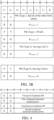
- FIG. 3A and FIG. 3B show MAC CE signaling formats for reporting the power headroom report.
- FIG. 3A shows MAC CE signaling format 1
- R represents a reserved bit
- PH represents power headroom information
- P CMAX,f,c represents a maximum transmit power.
- FIG. 3A shows MAC CE signaling format 1
- R represents a reserved bit
- PH represents power headroom information
- P CMAX,f,c represents a maximum transmit power.
- 3B shows MAC CE signaling format 2
- R represents a reserved bit
- PH represents power headroom information
- P CMAX,f,c represents a maximum transmit power
- P indicates information related to calculation of the power headroom
- V indicates information related to calculation of P CMAX,f,c
- C7-C1 respectively indicate, through one bit, whether the power headroom and the maximum transmit power of a corresponding cell are reported, that is, whether the power headroom and the maximum transmit power are carried in this signaling.
- S220 of determining, by the terminal device, according to the preset rule, to use the first configured maximum transmit power and/or the second configured maximum transmit power to obtain the power headroom report includes S223.
- the terminal device determines, according to the preset rule, to use at least one of the following modes to determine the power headroom report.
- the terminal device calculates a first power headroom by using the first configured maximum transmit power; the power headroom report includes the first power headroom and/or the first configured maximum transmit power.
- the terminal device calculates a second power headroom by using the second configured maximum transmit power; the power headroom report includes the second power headroom and/or the second configured maximum transmit power.
- S223 of determining, by the terminal device, according to the preset rule, to use at least one of the following modes to determine the power headroom report includes: determining, by the terminal device, according to a protocol, to use the first mode and/or the second mode to determine the power headroom report.
- An advantage of the first mode lies in that a case where a transmission power is low, that is, a case where a transmission limit is increased additionally, is taken into key account, so as to ensure that the network knows the worst case, so that the network device performs corresponding optimization.
- An advantage of the second mode lies in that a case where a transmission power is high, that is, a case where a transmission limit is less, is taken into key account, so as to ensure that the network device can make full use of transmit power, improving the network throughput.
- An advantage of using both the first and second modes to determine the power headroom report lies in that both the case where the transmission power is low and the case where the transmission power is high are taken into account, which is more comprehensive.
- S223 of determining, by the terminal device, according to the preset rule, to use at least one of the following modes to determine the power headroom report includes: determining, by the terminal device, according to configuration information, to use the first mode and/or the second mode to determine the power headroom report.
- the terminal device determines the mode of reporting the power headroom according to the configuration information in S223, optionally, 5220 of determining, by the terminal device, according to the preset rule, to use the first configured maximum transmit power and/or the second configured maximum transmit power to obtain the power headroom report further includes S221.
- the configuration information sent by the network device is received, wherein the configuration information is used for indicating the terminal device to determine, according to the configuration information, to use the first configured maximum transmit power and/or the second configured maximum transmit power to obtain the power headroom report.
- both the first mode and the second mode are adopted, and the power headroom report can be any one of the following combinational information: the first power headroom, and/or the first configured maximum transmit power; and the second power headroom, and/or the second configured maximum transmit power.
- the power headroom report is determined by using both the first mode and the second mode, and the power headroom report can be any one of the following combinational information:
- an advantage of the combinational information 2) to 7) above lies in that the reported information can be reduced and the overhead can be reduced.
- the network configuration is sent to the terminal device through radio resource control (RRC) signaling or medium access control control element (MAC CE) signaling.
- RRC radio resource control
- MAC CE medium access control control element
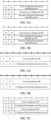
- FIG. 4 it shows a power headroom report in which combinational information 1) is reported by using MAC CE signaling format 1.
- FIGs. 5A and 5B they show power headroom reports in which combinational information 4) is reported by using MAC CE signaling format 1.
- FIGs. 6A and 6B they show power headroom reports in which combinational information 5) is reported by using MAC CE signaling format 1.
- FIG. 7 it shows a power headroom report in which combinational information 6) is reported by using MAC CE signaling format 1.
- FIGs. 8A and 8B show power headroom reports in which combinational information 7) is reported by using MAC CE signaling format 1.
- An example of reporting the power headroom report by using MAC CE signaling format 2 is the same as or similar to the example of reporting the power headroom report by using MAC CE signaling format 1, which is given only in the first implementation, and will not be repeated herein.
- an order in which information is reported can be more other orders.
- an order, in which the information is arranged, in the MAC CE signaling can be preset by a protocol; which type of information the corresponding information is can also be indicated by using reserved bits in an MAC CE signaling format.
- the original reserved bits R are used for indicating whether the corresponding information is the first power headroom or the second power headroom, and whether it is the first configured maximum transmit power or the second configured maximum transmit power.
- S223 of determining, by the terminal device, according to the preset rule, to use at least one of the following modes to determine the power headroom report includes: determining, by the terminal device, according to a type of the power headroom report, to use the first mode and/or the second mode to determine the power headroom report. Its advantage lies in that different reporting modes are determined according to different types of the report, so that the network can know more information and provide more optimization spaces for parameter configuration and scheduling.
- the types of the power headroom report include type 1 PHR and type 3 PHR.
- the type 1 PHR adopts the first mode to determine the power headroom report
- the type 3 PHR adopts the second mode to determine the power headroom report.
- the type 1 PHR adopts the second mode and the type 3 PHR adopts the first mode.
- the power headroom is determined according to a difference between the configured maximum transmit power P cmax,f,c (nominal UE maximum transmit power or configured maximum output power) of the terminal device and the transmit power of data channel (the estimated power for UL-SCH transmission), wherein c represents a serving cell, and f represents a carrier f of the serving cell c.
- P cmax,f,c nominal UE maximum transmit power or configured maximum output power
- f represents a carrier f of the serving cell c.
- SUL Supplemental UL
- the terminal device can calculate the power headroom (PH) according to actual PUSCH transmission, or calculate the power headroom according to reference PUSCH transmission, that is, no actual PUSCH transmission occurs, and the power headroom is calculated according to some parameters corresponding to the PUSCH transmission.
- the power headroom is determined according to a difference between the configured maximum transmit power P CMAX,f,c of the terminal device and channel sounding reference signal (SRS) transmit power.
- the terminal device can calculate the power headroom according to actual SRS transmission, or calculate the power headroom according to reference SRS transmission, that is, the actual SRS transmission does not occur, and the power headroom is calculated according to some parameters corresponding to the SRS transmission.
- the configured maximum transmit power includes the first configured maximum transmit power and/or the second configured maximum transmit power.
- S223 of determining, by the terminal device, according to the preset rule, to use at least one of the following modes to determine the power headroom report includes: determining, by the terminal device, according to whether the power headroom report is calculated based on actual transmission or reference transmission, to use the first mode and/or the second mode to determine the power headroom report. Its advantage lies in that different information is reported according to the power headroom calculated based on the actual transmission or the reference transmission, so that the network can know more information and provide more optimization spaces for parameter configuration and scheduling.
- the power headroom report is calculated based on the actual transmission, it is determined to use the first mode to determine the power headroom report; and/or if the power headroom report is calculated based on the reference transmission, it is determined to use the second mode to determine the power headroom report.
- determining, by the terminal device, according to whether the power headroom report is calculated based on the actual transmission or the reference transmission, to use the first mode and/or the second mode to determine the power headroom report includes:
- S223 of determining, by the terminal device, according to the preset rule, to use at least one of the following modes to determine the power headroom report includes: choosing voluntarily, by the terminal device, to use the first mode and/or the second mode to determine the power headroom report.
- the terminal device indicates in the power headroom report that the power headroom report is determined by using the first mode and/or the second mode.
- the power headroom report is reported by using MAC CE signaling format 1 when the terminal device chooses voluntarily the mode of reporting the power headroom.
- At least one of the reserved bits in MAC CE signaling format 1 is used to indicate whether it is the first power headroom or the second power headroom, and whether it is the first configured maximum transmit power or the second configured maximum transmit power.
- F indicates whether it corresponds to the first power headroom/the first configured maximum transmit power or the second power headroom/the second configured maximum transmit power.
- F can be any one of four reserved bits R.
- the first F indicates whether it is the first power headroom or the second power headroom, and the first F can be one of two reserved bits R in the first row; the second F indicates whether it is the first configured maximum transmit power or the second configured maximum transmit power, and the second F can be any one of two reserved bits R in the second row.
- the first F indicates whether it is the first power headroom or the second power headroom, and F can be any one of two reserved bits R in the first row;
- the second F indicates whether it is the first configured maximum transmit power or the second configured maximum transmit power, and the second F can be any one of two reserved bits R in the second row;
- the third F indicates whether it corresponds to the first power headroom or the second power headroom, and the third F can be any one of two reserved bits R in the third row;
- the fourth F indicates whether it corresponds to the first configured maximum transmit power or the second configured maximum transmit power, and the fourth F can be any one of two reserved bits R in the fourth row.
- An example of reporting the power headroom report by using MAC CE signaling format 2 is the same as or similar to the example of reporting the power headroom report by using MAC CE signaling format 1, which is given only in the first implementation, and will not be repeated herein.
- S223 of determining, by the terminal device, according to the preset rule, to use at least one of the following modes to determine the power headroom report includes: using, by the terminal device, the first configured maximum transmit power to calculate the first power headroom.
- the terminal device determines the power headroom report by using the second mode; otherwise, the terminal device determines the power headroom report by using the first mode.
- the transmit power limit is configured in a radio resource control information element (RRC IE). Specifically, the transmit power limit is configured in PhysicalCellGroupConfig of the RRC IE.
- the first transmit power limit PCG1 is configured through one of the following RRC parameters: p-MCG-FR1, p-SCG-FR1, p-MCG-FR2, p-SCG-FR2, p-NR-FR1 and p-NR-FR2 ⁇
- the first cell group and the second cell group are in the same frequency band.
- both the first cell group and the second cell group are in an FR1 frequency band; or both the first cell group and the second cell group are in an FR2 frequency band.
- the FR1 frequency band is 410 MHz - 7125 MHz; the FR2 frequency band is 24250 MHz - 52600 MHz.
- a power sharing mode between the first cell group and the second cell group is configured by the network device or reported by the terminal device.
- the power sharing mode is configured by an RRC parameter.
- the RRC parameter is NR-DC-PC-mode, which is configured in RRC IE PhysicalCellGroupConFIG.
- the power headroom report is transmitted through the first cell group or the second cell group.
- the terminal device determines, through some rule, to adopt which mode to calculate the power headroom and determines specific contents of reporting of the power headroom, thereby solving the problem of uncertainties in the calculation of the power headroom.
- FIG. 10 it shows an apparatus 300 for power headroom reporting in accordance with the second implementation of the present disclosure.
- the apparatus includes: a cell configuring unit 310, a determining unit 320, and a reporting unit 330.
- the cell configuring unit 310 is configured to determine a cell group configured by a network, wherein the cell group is configured with a transmit power limit P CG1 , and the apparatus 300 corresponds to a first configured maximum transmit power and a second configured maximum transmit power for the cell group; wherein the first configured maximum transmit power is determined based on the transmit power limit P CG1 , and determination of the second configured maximum transmit power is irrelevant to the transmit power limit P CG1 .
- the determining unit 320 is configured to determine, according to a preset rule, to use the first configured maximum transmit power and/or the second configured maximum transmit power to obtain a power headroom report.
- the reporting unit 330 is configured to report the power headroom report.
- the determining unit 320 is specifically configured to determine, according to the preset rule, to use at least one of the following modes to determine the power headroom report.
- the first power headroom is calculated by using the first configured maximum transmit power; the power headroom report includes the first power headroom and/or the first configured maximum transmit power.
- the second power headroom is calculated by using the second configured maximum transmit power; the power headroom report includes the second power headroom and/or the second configured maximum transmit power.
- the determining unit 320 is specifically configured to determine, according to the protocol, to use the first mode and/or the second mode to determine the power headroom report.
- the determining unit 320 is specifically configured to determine, according to network configuration, to use the first mode and/or the second mode to determine the power headroom report.
- the power headroom report includes any one of the following combinational information:
- the network configuration is sent to the terminal device through radio resource control (RRC) signaling or medium access control control element (MAC CE) signaling.
- RRC radio resource control
- MAC CE medium access control control element
- the reporting unit 330 is specifically configured to report the power headroom report through the MAC CE signaling.
- an order, in which the information is arranged, in the MAC CE signaling is preset by a protocol; and/or reserved bits in an MAC CE signaling format are used for indicating that the corresponding information is one of the first power headroom, the second power headroom, the first configured maximum transmit power, and the second configured maximum transmit power.
- the determining unit 320 is specifically configured to determine, according to a type of the power headroom report, to use the first mode and/or the second mode to determine the power headroom report.
- the determining unit 320 is specifically configured to determine, according to whether the power headroom report is calculated based on actual transmission or reference transmission, to use the first mode and/or the second mode to determine the power headroom report.
- the determining unit 320 is specifically configured to, if the power headroom report is calculated based on the reference transmission, use the second mode to determine the power headroom report; or if the power headroom report is calculated based on the actual transmission, when the actual transmission is overlapped with transmission or potential transmission on a second cell group in the time domain, use the first mode to determine the power headroom report, otherwise, use the second mode to determine the power headroom report.
- the determining unit 320 is specifically configured to choose voluntarily to use the first mode and/or the second mode to determine the power headroom report.
- the determining unit 320 is further configured to indicate in the power headroom report that the first mode and/or the second mode is used for determining the power headroom report.
- the determining unit 320 is specifically configured to calculate the first power headroom by using the first configured maximum transmit power; use the second mode to determine the power headroom report when the first power headroom is less than or equal to 0; otherwise, use the first mode to determine the power headroom report.
- FIG. 11 it is a block diagram of an apparatus 400 for power headroom reporting in accordance with the third implementation of the present disclosure.
- the apparatus includes: a network configuring unit 410, an indicating unit 420, and a report receiving unit 430.
- the network configuring unit 410 is configured to configure a cell group for a terminal device, wherein the cell group is configured with a transmit power limit P CG1 , and the terminal device corresponds to a first configured maximum transmit power and a second configured maximum transmit power for the cell group; wherein the first configured maximum transmit power is determined based on the transmit power limit P CG1 , and determination of the second configured maximum transmit power is irrelevant to the transmit power limit P CG1 .
- the indicating unit 420 is configured to send configuration information to the terminal device to indicate the terminal device to determine, according to the configuration information, to use the first configured maximum transmit power and/or the second configured maximum transmit power to obtain a power headroom report.
- the report receiving unit 430 is configured to receive the power headroom report reported by the terminal device.
- the configuration information is used for indicating whether the terminal device uses the first mode or the second mode to determine the power headroom report.
- the indicating unit 420 is configured to send the configuration information to the terminal device through radio resource control (RRC) signaling or medium access control control element (MAC CE) signaling.
- RRC radio resource control
- MAC CE medium access control control element
- the report receiving unit 430 is specifically configured to receive the power headroom report reported by the terminal device through the MAC CE signaling.
- the MAC CE signaling For specific formats and contents of the MAC CE signaling, reference is made to the contents in the first implementation described above and this will not be repeated herein.
- the network configuring unit 410 is configured to configure the transmit power limit through a radio resource control information element (RRC IE).
- RRC IE radio resource control information element
- the network device configures two cell groups, i.e., a first cell group and a second cell group, for the terminal device, the first cell group and the second cell group are in the same frequency band.
- the report receiving unit is configured to receive the power headroom report through the first cell group or the second cell group.
- FIG. 12 it is a schematic structural diagram of an apparatus 500 for power headroom reporting in accordance with the fourth implementation of the present disclosure.
- the apparatus 500 includes a processor 510, a memory 520, and a network interface 530.
- the processor 510 invokes a program in the memory 520 to execute a method for power headroom reporting in accordance with the first implementation, and send out an execution result through the network interface 530.
- the processor 510 may be an independent component or a unified name of a plurality of processing elements.
- the processor may be a CPU, an ASIC, or one or more integrated circuits configured to implement the methods described above, such as at least one digital signal processor (DSP) or at least one field programmable gate array (FPGA).
- DSP digital signal processor
- FPGA field programmable gate array
Landscapes
- Engineering & Computer Science (AREA)
- Computer Networks & Wireless Communication (AREA)
- Signal Processing (AREA)
- Mobile Radio Communication Systems (AREA)
Claims (15)
- Verfahren für "Power Headroom"-Berichterstattung von "New Radio-New Radio"-, "NR-NR"-, "Dual Connectivity", umfassend:Empfangen, durch ein Endgerät, einer "Radio Resource Control"-, RRC-, Signalisierung von einer Netzvorrichtung; wobei ein "Information Element", IE, der RRC-Signalisierung eine Sendeleistungsgrenze des Endgeräts in einer Zellengruppe umfasst; wobei die Sendeleistungsgrenze verwendet wird, um einen "Power Headroom Report" zu erhalten, die auf einer ersten ausgelegten maximalen Sendeleistung basiert, die auf der Grundlage der Sendeleistungsgrenze des Endgeräts in der Zellengruppe bestimmt wird;Bestimmen (S220), durch das Endgerät, gemäß einer voreingestellten Regel, dass der "Power Headroom Report" auf der Grundlage einer zweiten ausgelegten maximalen Sendeleistung des Endgeräts in der Zellengruppe zu erhalten ist, wenn sich Uplink-Übertragung des Endgeräts in der Zellengruppe nicht mit einem semistatisch ausgelegten Uplink- oder flexiblen Symbol einer anderen Zellengruppe überschneidet, oder wenn sich Uplink-Übertragung des Endgeräts in der Zellengruppe nicht mit Uplink-Übertragung in der anderen Zellengruppe überschneidet, wobei die Sendeleistungsgrenze des Endgeräts in der Zellengruppe nicht berücksichtigt wird, wenn die zweite ausgelegte maximale Sendeleistung berechnet wird, wobei die Zellengruppe eine "Master Cell Group" oder eine "Secondary Cell Group" umfasst; undMelden (S230), durch das Endgerät, des "Power Headroom Report" (S230);wobei der "Power Headroom Report" einen zweiten "Power Headroom" und die zweite ausgelegte maximale Sendeleistung umfasst, wobei der zweite "Power Headroom" auf der Grundlage der zweiten ausgelegten maximalen Sendeleistung erhalten wird.
- Verfahren nach Anspruch 1, ferner umfassend:
Bestimmen, durch das Endgerät, gemäß der voreingestellten Regel, dass der "Power Headroom Report" auf der Grundlage der ersten ausgelegten maximalen Sendeleistung zu erhalten ist, wenn sich Uplink-Übertragung des Endgeräts in der Zellengruppe mit dem semistatisch ausgelegten Uplink- oder flexiblen Symbol der anderen Zellengruppe überschneidet, oder wenn sich Uplink-Übertragung des Endgeräts in der Zellengruppe mit Uplink-Übertragung in der anderen Zellengruppe überschneidet, wobei der "Power Headroom Report" ferner umfasst:
einen ersten "Power Headroom" und die erste ausgelegte maximale Sendeleistung; wobei der erste "Power Headroom" auf der Grundlage der ersten ausgelegten maximalen Sendeleistung erhalten wird. - Verfahren nach Anspruch 1, wobei das Melden (S230), durch das Endgerät, des "Power Headroom Report" umfasst: Melden, durch das Endgerät, des "Power Headroom Report" über eine "Media Access Control"-, MAC-, "Control Element"-, CE-, Signalisierung.
- Verfahren nach Anspruch 3, wobei,
eine Reihenfolge, in der Informationen angeordnet sind, in der MAC-CE-Signalisierung durch ein Protokoll voreingestellt ist, wobei die Informationen eines oder mehrere von einem ersten "Power Headroom", dem zweiten "Power Headroom", der ersten ausgelegten maximalen Sendeleistung und der zweiten ausgelegten maximalen Sendeleistung umfassen. - Verfahren nach einem der Ansprüche 1 bis 4, wobei der "Power Headroom Report", PHR, PHR vom Typ 1 und PHR vom Typ 3 umfasst;der PHR vom Typ 1 dazu dient, den "Power Headroom" gemäß einer Differenz zwischen einer ausgelegten maximalen Sendeleistung des Endgeräts und einer Sendeleistung des Datenkanals zu bestimmen; undder PHR vom Typ 3 dazu dient, den "Power Headroom" gemäß einer Differenz zwischen einer ausgelegten maximalen Sendeleistung des Endgeräts und einer Sendeleistung des Kanal-"Sounding Reference Signal", -SRS, zu bestimmen;wobei die ausgelegte maximale Sendeleistung die erste ausgelegte maximale Sendeleistung oder die zweite ausgelegte maximale Sendeleistung umfasst.
- Verfahren für "Power Headroom"-Berichterstattung von "New Radio-New Radio"-, "NR-NR"-, "Dual Connectivity", umfassend:Auslegen, durch eine Netzvorrichtung, einer Zellengruppe für ein Endgerät, wobei die Zellengruppe mit einer Sendeleistungsgrenze des Endgeräts durch ein "Radio Resource Control"-"Information Element", RRC IE, ausgelegt wird, wobei die Sendeleistungsgrenze zum Erhalten eines "Power Headroom Report" auf der Grundlage einer ersten ausgelegten maximalen Sendeleistung verwendet wird, die auf der Grundlage der Sendeleistungsgrenze des Endgeräts in der Zellengruppe bestimmt wird; wobei die Zellengruppe eine "Master Cell Group" oder eine "Secondary Cell Group" umfasst;Senden, durch die Netzvorrichtung, von Auslegungsinformationen an das Endgerät, um das Endgerät in die Lage zu versetzen, zu bestimmen, gemäß den Auslegungsinformationen, dass der "Power Headroom Report" zu erhalten ist; undEmpfangen, durch die Netzvorrichtung, des vom Endgerät gemeldeten "Power Headroom Report",wobei, wenn sich Uplink-Übertragung des Endgeräts in der Zellengruppe nicht mit einem semistatisch ausgelegten Uplink- oder flexiblen Symbol einer anderen Zellengruppe überschneidet, oder wenn sich Uplink-Übertragung des Endgeräts in der Zellengruppe nicht mit Uplink-Übertragung in der anderen Zellengruppe überschneidet, die Sendeleistungsgrenze des Endgeräts in der Zellengruppe nicht berücksichtigt wird, wenn eine zweite ausgelegte maximale Sendeleistung berechnet wird, wobei der "Power Headroom Report" einen zweiten "Power Headroom" und die zweite ausgelegte maximale Sendeleistung umfasst, wobei der zweite "Power Headroom" auf der Grundlage der zweiten ausgelegten maximalen Sendeleistung erhalten wird.
- Verfahren nach Anspruch 6, wobei die Auslegungsinformationen ferner dazu verwendet werden, dem Endgerät anzuzeigen, dass es den "Power Headroom Report" im folgenden Modus erhalten soll:
wenn sich Uplink-Übertragung des Endgeräts in der Zellengruppe mit einem semistatisch ausgelegten Uplink- oder flexiblen Symbol der anderen Zellengruppe überschneidet, oder wenn sich Uplink-Übertragung des Endgeräts in der Zellengruppe mit Uplink-Übertragung in der anderen Zellengruppe überschneidet, der "Power Headroom Report" einen ersten "Power Headroom" und die erste ausgelegte maximale Sendeleistung umfasst; wobei der erste "Power Headroom" auf der Grundlage der ersten ausgelegten maximalen Sendeleistung erhalten wird. - Verfahren nach Anspruch 6 oder 7, wobei das Empfangen, durch die Netzvorrichtung, des vom Endgerät gemeldeten "Power Headroom Report" das Empfangen, durch die Netzvorrichtung, des vom Endgerät gemeldeten "Power Headroom Report" durch eine "Media Access Control"-, MAC-, "Control Element"-, CE-, Signalisierung umfasst,
wobei eine Reihenfolge, in der Informationen angeordnet sind, in der MAC-CE-Signalisierung durch ein Protokoll voreingestellt ist, wobei die Informationen eines oder mehrere von einem ersten "Power Headroom", dem zweiten "Power Headroom", der ersten ausgelegten maximalen Sendeleistung und der zweiten ausgelegten maximalen Sendeleistung umfassen. - Vorrichtung (300) für "Power Headroom"-Berichterstattung, umfassend:eine Zellauslegungseinheit (310), die dafür ausgelegt ist, eine "Radio Resource Control"-, RRC-, Signalisierung von einer Netzvorrichtung zu empfangen; wobei ein "Information Element", IE, der RRC-Signalisierung eine Sendeleistungsgrenze des Endgeräts in einer Zellengruppe umfasst; wobei die Sendeleistungsgrenze verwendet wird, um einen "Power Headroom Report" zu erhalten, die auf einer ersten ausgelegten maximalen Sendeleistung basiert, die auf der Grundlage der Sendeleistungsgrenze des Endgeräts in der Zellengruppe bestimmt wird;eine Bestimmungseinheit (320), die dafür ausgelegt ist, zu bestimmen, gemäß einer voreingestellten Regel, dass der "Power Headroom Report" auf der Grundlage einer zweiten ausgelegten maximalen Sendeleistung des Endgeräts in der Zellengruppe zu erhalten ist, wenn sich Uplink-Übertragung des Endgeräts in der Zellengruppe nicht mit einem semistatisch ausgelegten Uplink- oder flexiblen Symbol einer anderen Zellengruppe überschneidet, oder wenn sich Uplink-Übertragung des Endgeräts in der Zellengruppe nicht mit Uplink-Übertragung in der anderen Zellengruppe überschneidet, wobei die Sendeleistungsgrenze des Endgeräts in der Zellengruppe nicht berücksichtigt wird, wenn die zweite ausgelegte maximale Sendeleistung berechnet wird, wobei die Zellengruppe eine "Master Cell Group" oder eine "Secondary Cell Group" umfasst; undeine Meldeeinheit (330), die dafür ausgelegt ist, den "Power Headroom Report" zu melden;wobei der "Power Headroom Report" einen zweiten "Power Headroom" und die zweite ausgelegte maximale Sendeleistung umfasst, wobei der zweite "Power Headroom" auf der Grundlage der zweiten ausgelegten maximalen Sendeleistung erhalten wird.
- Vorrichtung nach Anspruch 9, wobei
die Bestimmungseinheit (320) ferner dafür ausgelegt ist, zu bestimmen, gemäß der voreingestellten Regel, dass der "Power Headroom Report" auf der Grundlage der ersten ausgelegten maximalen Sendeleistung zu erhalten ist, wenn sich Uplink-Übertragung des Endgeräts in der Zellengruppe mit dem semistatisch ausgelegten Uplink- oder flexiblen Symbol der anderen Zellengruppe überschneidet, oder wenn sich Uplink-Übertragung des Endgeräts in der Zellengruppe mit Uplink-Übertragung in der anderen Zellengruppe überschneidet, wobei der "Power Headroom Report" ferner umfasst:
einen ersten "Power Headroom" und die erste ausgelegte maximale Sendeleistung; wobei der erste "Power Headroom" auf der Grundlage der ersten ausgelegten maximalen Sendeleistung erhalten wird. - Vorrichtung nach Anspruch 9, wobei die Meldeeinheit (330) dafür ausgelegt ist, den "Power Headroom Report" durch eine "Media Access Control"-, MAC-, "Control Element"-, CE-, Signalisierung zu melden.
- Vorrichtung nach Anspruch 11, wobei eine Reihenfolge, in der Informationen angeordnet sind, in der MAC-CE-Signalisierung durch ein Protokoll voreingestellt ist, wobei die Informationen eines oder mehrere von einem ersten "Power Headroom", dem zweiten "Power Headroom", der ersten ausgelegten maximalen Sendeleistung und der zweiten ausgelegten maximalen Sendeleistung umfassen.
- Vorrichtung (400) für "Power Headroom"-Berichterstattung, umfassend:eine Netzauslegungseinheit (410), die dafür ausgelegt ist, eine Zellengruppe für ein Endgerät auszulegen, wobei die Zellengruppe mit einer Sendeleistungsgrenze des Endgeräts durch ein "Radio Resource Control"-"Information Element", RRC-IE, ausgelegt wird, wobei die Sendeleistungsgrenze zum Erhalten eines "Power Headroom Report" auf der Grundlage einer ersten ausgelegten maximalen Sendeleistung verwendet wird, die auf der Grundlage der Sendeleistungsgrenze des Endgeräts in der Zellengruppe bestimmt wird; wobei die Zellengruppe eine "Master Cell Group" oder eine "Secondary Cell Group" umfasst;eine Anzeigeeinheit (420), die dafür ausgelegt ist, Auslegungsinformationen an das Endgerät zu senden, um das Endgerät in die Lage zu versetzen, zu bestimmen, gemäß den Auslegungsinformationen, dass der "Power Headroom Report" zu erhalten ist; undeine Meldungsempfangseinheit (430), die dafür ausgelegt ist, den vom Endgerät gemeldeten "Power Headroom Report" zu empfangen;wobei, wenn sich Uplink-Übertragung des Endgeräts in der Zellengruppe nicht mit einem semistatisch ausgelegten Uplink- oder flexiblen Symbol einer anderen Zellengruppe überschneidet, oder wenn sich Uplink-Übertragung des Endgeräts in der Zellengruppe nicht mit Uplink-Übertragung in der anderen Zellengruppe überschneidet, die Sendeleistungsgrenze des Endgeräts in der Zellengruppe nicht berücksichtigt wird, wenn eine zweite ausgelegte maximale Sendeleistung berechnet wird, wobei der "Power Headroom Report" einen zweiten "Power Headroom" und die zweite ausgelegte maximale Sendeleistung umfasst, wobei der zweite "Power Headroom" auf der Grundlage der zweiten ausgelegten maximalen Sendeleistung erhalten wird.
- Vorrichtung nach Anspruch 13, wobei die Auslegungsinformationen ferner dazu verwendet werden, dem Endgerät anzuzeigen, dass es den "Power Headroom Report" im folgenden Modus erhalten soll:
wenn sich Uplink-Übertragung des Endgeräts in der Zellengruppe mit dem semistatisch ausgelegten Uplink- oder flexiblen Symbol der anderen Zellengruppe überschneidet, oder wenn sich Uplink-Übertragung des Endgeräts in der Zellengruppe mit Uplink-Übertragung in der anderen Zellengruppe überschneidet, der "Power Headroom Report" einen ersten "Power Headroom" und die erste ausgelegte maximale Sendeleistung umfasst; wobei der erste "Power Headroom" auf der Grundlage der ersten ausgelegten maximalen Sendeleistung erhalten wird. - Vorrichtung nach Anspruch 13 oder 14, wobei die Meldungsempfangseinheit (430) dafür ausgelegt ist, den vom Endgerät über eine "Media Access Control"-, MAC-, "Control Element"-, CE-, Signalisierung gemeldeten "Power Headroom Report" zu empfangen,
wobei eine Reihenfolge, in der Informationen angeordnet sind, in der MAC-CE-Signalisierung durch ein Protokoll voreingestellt ist, wobei die Informationen eines oder mehrere von einem ersten "Power Headroom", dem zweiten "Power Headroom", der ersten ausgelegten maximalen Sendeleistung und der zweiten ausgelegten maximalen Sendeleistung umfassen.
Applications Claiming Priority (1)
| Application Number | Priority Date | Filing Date | Title |
|---|---|---|---|
| PCT/CN2019/116693 WO2021087977A1 (zh) | 2019-11-08 | 2019-11-08 | 功率余量上报方法及其装置 |
Publications (3)
| Publication Number | Publication Date |
|---|---|
| EP3986038A1 EP3986038A1 (de) | 2022-04-20 |
| EP3986038A4 EP3986038A4 (de) | 2022-07-27 |
| EP3986038B1 true EP3986038B1 (de) | 2025-01-01 |
Family
ID=75849125
Family Applications (1)
| Application Number | Title | Priority Date | Filing Date |
|---|---|---|---|
| EP19951979.4A Active EP3986038B1 (de) | 2019-11-08 | 2019-11-08 | Leistungsreservemeldeverfahren und vorrichtung dafür |
Country Status (4)
| Country | Link |
|---|---|
| US (1) | US12445976B2 (de) |
| EP (1) | EP3986038B1 (de) |
| CN (2) | CN115002887B (de) |
| WO (1) | WO2021087977A1 (de) |
Families Citing this family (1)
| Publication number | Priority date | Publication date | Assignee | Title |
|---|---|---|---|---|
| JP7153035B2 (ja) * | 2017-10-30 | 2022-10-13 | オッポ広東移動通信有限公司 | 信号伝送方法、ネットワーク装置と端末装置 |
Family Cites Families (31)
| Publication number | Priority date | Publication date | Assignee | Title |
|---|---|---|---|---|
| KR100594101B1 (ko) * | 2003-01-20 | 2006-06-30 | 삼성전자주식회사 | 비추적 영역에서 멀티캐스트 멀티미디어 방송 서비스를제공하는 시스템 및 방법 |
| KR20150023886A (ko) * | 2008-12-03 | 2015-03-05 | 인터디지탈 패튼 홀딩스, 인크 | 캐리어 집적에 대한 업링크 파워 헤드룸 보고 |
| JP5020300B2 (ja) * | 2009-10-28 | 2012-09-05 | シャープ株式会社 | 無線通信システム、移動局装置、基地局装置、無線通信方法および移動局装置の制御プログラム |
| EP2317815A1 (de) * | 2009-11-02 | 2011-05-04 | Panasonic Corporation | Leistungsgrenzenmeldung in einem Carrier-Aggregation-Kommunikationssystem |
| EP2360866A1 (de) * | 2010-02-12 | 2011-08-24 | Panasonic Corporation | Aktivierung bzw. Deaktivierung von Frequenzkomponenten mithilfe von Ressourcenzuweisungen |
| US20120196605A1 (en) * | 2010-08-27 | 2012-08-02 | Sonus Networks, Inc. | Transfer of Sessions for Femtocells to Macro Mobile Networks |
| US9807709B2 (en) * | 2012-05-31 | 2017-10-31 | Interdigital Patent Holdings, Inc. | Device to-device (D2D) cross link power control |
| KR20140133408A (ko) * | 2013-05-10 | 2014-11-19 | 주식회사 팬택 | 무선 통신 시스템에서 최대송신전력 설정 및 시그널링 방법 및 장치 |
| WO2015047184A1 (en) * | 2013-09-27 | 2015-04-02 | Telefonaktiebolaget L M Ericsson (Publ) | Method and arrangement for power control handling |
| CN104936278B (zh) * | 2014-03-20 | 2019-06-11 | 中兴通讯股份有限公司 | 功率余量报告phr处理方法、装置、终端及基站 |
| JP6298329B2 (ja) * | 2014-03-20 | 2018-03-20 | 株式会社Nttドコモ | ユーザ端末、無線基地局および無線通信方法 |
| US9357510B2 (en) * | 2014-03-31 | 2016-05-31 | Qualcomm Incorporated | Power sharing and power headroom reporting in dual connectivity scenarios |
| EP3128791B1 (de) * | 2014-04-03 | 2019-03-20 | LG Electronics Inc. | Verfahren und endgerät zur übertragung von leistungsreserveberichten in einer dualen verbindung zwischen endgerät und basisstation |
| US10314078B2 (en) * | 2014-06-05 | 2019-06-04 | Sharp Kabushiki Kaisha | Terminal device, base station apparatus, and method |
| JP6587612B2 (ja) * | 2014-06-20 | 2019-10-09 | シャープ株式会社 | 端末装置、基地局装置、および通信方法 |
| EP3172923B1 (de) * | 2014-07-23 | 2019-10-23 | Samsung Electronics Co., Ltd. | Verfahren und vorrichtung zur erzeugung und übertragung eines leistungsreserveberichts in einem mobilkommunikationssystem |
| JP2017175174A (ja) * | 2014-08-08 | 2017-09-28 | シャープ株式会社 | 端末装置、基地局装置および方法 |
| US10194406B2 (en) * | 2015-09-30 | 2019-01-29 | Ofinno Technologies, Llc | Multi-carrier power headroom in a wireless network |
| CN107889209B (zh) * | 2016-09-29 | 2023-09-22 | 华为技术有限公司 | 一种功率控制的方法及终端设备 |
| US10912041B2 (en) * | 2017-08-11 | 2021-02-02 | Lg Electronics Inc. | Method for triggering a power headroom reporting in wireless communication system and a device therefor |
| EP3698582B1 (de) * | 2017-11-15 | 2022-09-14 | Convida Wireless, LLC | Verfahren und vorrichtung zur leistungsreservenmeldung in 5g nr |
| WO2019141238A1 (en) * | 2018-01-18 | 2019-07-25 | Fg Innovation Ip Company Limited | Reporting power headroom in multiple connectivity next generation networks |
| EP3751913B1 (de) * | 2018-02-09 | 2025-07-09 | Ntt Docomo, Inc. | Benutzerausrüstung |
| CN110167123B (zh) * | 2018-02-14 | 2021-06-15 | 华为技术有限公司 | 一种功率控制方法及装置 |
| US10893487B2 (en) * | 2018-02-15 | 2021-01-12 | Telefonaktiebolaget Lm Ericsson (Publ) | Power headroom reporting for higher frequency carriers in NR |
| WO2020032866A1 (en) * | 2018-08-10 | 2020-02-13 | Telefonaktiebolaget L M Ericsson (Publ) | Power headroom report (phr) reporting determination |
| US11510156B2 (en) * | 2018-08-29 | 2022-11-22 | Samsung Electronics Co., Ltd. | Apparatus and method for dynamic power management in wireless communication system |
| US10827440B2 (en) * | 2018-11-02 | 2020-11-03 | Qualcomm Incorporated | Indication of potential NR UL transmission in NE-DC |
| US11553443B2 (en) * | 2019-01-02 | 2023-01-10 | Qualcomm Incorporated | Power headroom reporting procedure for multiple cells |
| US10986591B2 (en) * | 2019-03-29 | 2021-04-20 | Lenovo (Singapore) Pte. Ltd. | Transmission power for dual connectivity |
| WO2021042365A1 (en) * | 2019-09-06 | 2021-03-11 | Qualcomm Incorporated | Uplink cross-carrier scheduling for time division multiplexing carrier aggregation |
-
2019
- 2019-11-08 CN CN202210161887.7A patent/CN115002887B/zh active Active
- 2019-11-08 CN CN201980097853.2A patent/CN114041306A/zh active Pending
- 2019-11-08 EP EP19951979.4A patent/EP3986038B1/de active Active
- 2019-11-08 WO PCT/CN2019/116693 patent/WO2021087977A1/zh not_active Ceased
-
2022
- 2022-02-11 US US17/650,739 patent/US12445976B2/en active Active
Non-Patent Citations (2)
| Title |
|---|
| ANONYMOUS: "3rd Generation Partnership Project; Technical Specification Group Radio Access Network; NR; Medium Access Control (MAC) protocol specification (Release 15)", vol. RAN WG2, no. V15.7.0, 27 September 2019 (2019-09-27), pages 1 - 78, XP051785032, Retrieved from the Internet <URL:ftp://ftp.3gpp.org/Specs/archive/38_series/38.321/38321-f70.zip 38321-f70.docx> [retrieved on 20190927] * |
| ANONYMOUS: "3rd Generation Partnership Project; Technical Specification Group Radio Access Network; NR; Radio Resource Control (RRC) protocol specification (Release 15)", vol. RAN WG2, no. V15.7.0, 27 September 2019 (2019-09-27), pages 1 - 527, XP051785033, Retrieved from the Internet <URL:ftp://ftp.3gpp.org/Specs/archive/38_series/38.331/38331-f70.zip 38331-f70.docx> [retrieved on 20190927] * |
Also Published As
| Publication number | Publication date |
|---|---|
| US12445976B2 (en) | 2025-10-14 |
| EP3986038A1 (de) | 2022-04-20 |
| CN115002887B (zh) | 2024-01-16 |
| CN114041306A (zh) | 2022-02-11 |
| EP3986038A4 (de) | 2022-07-27 |
| WO2021087977A1 (zh) | 2021-05-14 |
| CN115002887A (zh) | 2022-09-02 |
| WO2021087977A9 (zh) | 2021-11-25 |
| US20220174614A1 (en) | 2022-06-02 |
Similar Documents
| Publication | Publication Date | Title |
|---|---|---|
| US11006473B2 (en) | Resource scheduling method and apparatus | |
| US11395273B2 (en) | Method and apparatus for uplink transmission in multi-carrier systems | |
| US11956177B2 (en) | Resource allocation method, terminal device, and network device | |
| US12058707B2 (en) | Communication method in D2D system, terminal device, and network device | |
| CN116436582A (zh) | Ssb确定方法、装置、设备及存储介质 | |
| EP3534658A1 (de) | Ressourcenanzeigeverfahren, -vorrichtung und -system | |
| US20240204908A1 (en) | Wireless communication method and communication apparatus | |
| WO2020168575A1 (zh) | 无线通信方法、终端设备和网络设备 | |
| KR20220097868A (ko) | 신호 감청 방법, 송신 방법, 단말 기기, 네트워크 기기 | |
| CN105517044B (zh) | 一种干扰协调的方法及系统 | |
| US10251135B2 (en) | Method for controlling power of carrier signal, user equipment, and base station | |
| EP4369769A1 (de) | Kommunikationsverfahren und -vorrichtung | |
| US12445976B2 (en) | Power headroom reporting method and apparatus therefor | |
| CN116097804B (zh) | 一种信号传输方法、电子设备及存储介质 | |
| WO2020087540A1 (zh) | 一种控制信息的传输方法、设备及存储介质 | |
| WO2020077745A1 (zh) | 一种连接配置方法、设备及存储介质 | |
| EP3624523B1 (de) | Drahtloses kommunikationsverfahren und endgerät | |
| CN118140516A (zh) | 一种资源分配指示域的确定方法及终端设备、网络设备 | |
| US20250016688A1 (en) | Systems, methods, and non-transitory processor-readable media for transmission power determination | |
| EP4560928A1 (de) | Kommunikationsverfahren und -vorrichtung |
Legal Events
| Date | Code | Title | Description |
|---|---|---|---|
| STAA | Information on the status of an ep patent application or granted ep patent |
Free format text: STATUS: THE INTERNATIONAL PUBLICATION HAS BEEN MADE |
|
| PUAI | Public reference made under article 153(3) epc to a published international application that has entered the european phase |
Free format text: ORIGINAL CODE: 0009012 |
|
| STAA | Information on the status of an ep patent application or granted ep patent |
Free format text: STATUS: REQUEST FOR EXAMINATION WAS MADE |
|
| 17P | Request for examination filed |
Effective date: 20220113 |
|
| AK | Designated contracting states |
Kind code of ref document: A1 Designated state(s): AL AT BE BG CH CY CZ DE DK EE ES FI FR GB GR HR HU IE IS IT LI LT LU LV MC MK MT NL NO PL PT RO RS SE SI SK SM TR |
|
| REG | Reference to a national code |
Ref country code: DE Ref legal event code: R079 Free format text: PREVIOUS MAIN CLASS: H04W0052140000 Ipc: H04W0052360000 Ref document number: 602019064486 Country of ref document: DE |
|
| A4 | Supplementary search report drawn up and despatched |
Effective date: 20220629 |
|
| RIC1 | Information provided on ipc code assigned before grant |
Ipc: H04W 52/14 20090101ALN20220623BHEP Ipc: H04W 52/36 20090101AFI20220623BHEP |
|
| DAV | Request for validation of the european patent (deleted) | ||
| DAX | Request for extension of the european patent (deleted) | ||
| STAA | Information on the status of an ep patent application or granted ep patent |
Free format text: STATUS: EXAMINATION IS IN PROGRESS |
|
| 17Q | First examination report despatched |
Effective date: 20230307 |
|
| GRAP | Despatch of communication of intention to grant a patent |
Free format text: ORIGINAL CODE: EPIDOSNIGR1 |
|
| STAA | Information on the status of an ep patent application or granted ep patent |
Free format text: STATUS: GRANT OF PATENT IS INTENDED |
|
| RIC1 | Information provided on ipc code assigned before grant |
Ipc: H04W 52/14 20090101ALN20240726BHEP Ipc: H04W 52/36 20090101AFI20240726BHEP |
|
| INTG | Intention to grant announced |
Effective date: 20240816 |
|
| GRAS | Grant fee paid |
Free format text: ORIGINAL CODE: EPIDOSNIGR3 |
|
| GRAA | (expected) grant |
Free format text: ORIGINAL CODE: 0009210 |
|
| STAA | Information on the status of an ep patent application or granted ep patent |
Free format text: STATUS: THE PATENT HAS BEEN GRANTED |
|
| AK | Designated contracting states |
Kind code of ref document: B1 Designated state(s): AL AT BE BG CH CY CZ DE DK EE ES FI FR GB GR HR HU IE IS IT LI LT LU LV MC MK MT NL NO PL PT RO RS SE SI SK SM TR |
|
| REG | Reference to a national code |
Ref country code: GB Ref legal event code: FG4D |
|
| REG | Reference to a national code |
Ref country code: CH Ref legal event code: EP |
|
| REG | Reference to a national code |
Ref country code: DE Ref legal event code: R096 Ref document number: 602019064486 Country of ref document: DE |
|
| REG | Reference to a national code |
Ref country code: IE Ref legal event code: FG4D |
|
| P01 | Opt-out of the competence of the unified patent court (upc) registered |
Free format text: CASE NUMBER: APP_9813/2025 Effective date: 20250226 |
|
| REG | Reference to a national code |
Ref country code: LT Ref legal event code: MG9D |
|
| REG | Reference to a national code |
Ref country code: NL Ref legal event code: MP Effective date: 20250101 |
|
| REG | Reference to a national code |
Ref country code: AT Ref legal event code: MK05 Ref document number: 1757596 Country of ref document: AT Kind code of ref document: T Effective date: 20250101 |
|
| PG25 | Lapsed in a contracting state [announced via postgrant information from national office to epo] |
Ref country code: NL Free format text: LAPSE BECAUSE OF FAILURE TO SUBMIT A TRANSLATION OF THE DESCRIPTION OR TO PAY THE FEE WITHIN THE PRESCRIBED TIME-LIMIT Effective date: 20250101 |
|
| PG25 | Lapsed in a contracting state [announced via postgrant information from national office to epo] |
Ref country code: FI Free format text: LAPSE BECAUSE OF FAILURE TO SUBMIT A TRANSLATION OF THE DESCRIPTION OR TO PAY THE FEE WITHIN THE PRESCRIBED TIME-LIMIT Effective date: 20250101 |
|
| PG25 | Lapsed in a contracting state [announced via postgrant information from national office to epo] |
Ref country code: PL Free format text: LAPSE BECAUSE OF FAILURE TO SUBMIT A TRANSLATION OF THE DESCRIPTION OR TO PAY THE FEE WITHIN THE PRESCRIBED TIME-LIMIT Effective date: 20250101 |
|
| PG25 | Lapsed in a contracting state [announced via postgrant information from national office to epo] |
Ref country code: ES Free format text: LAPSE BECAUSE OF FAILURE TO SUBMIT A TRANSLATION OF THE DESCRIPTION OR TO PAY THE FEE WITHIN THE PRESCRIBED TIME-LIMIT Effective date: 20250101 |
|
| PG25 | Lapsed in a contracting state [announced via postgrant information from national office to epo] |
Ref country code: IS Free format text: LAPSE BECAUSE OF FAILURE TO SUBMIT A TRANSLATION OF THE DESCRIPTION OR TO PAY THE FEE WITHIN THE PRESCRIBED TIME-LIMIT Effective date: 20250501 Ref country code: NO Free format text: LAPSE BECAUSE OF FAILURE TO SUBMIT A TRANSLATION OF THE DESCRIPTION OR TO PAY THE FEE WITHIN THE PRESCRIBED TIME-LIMIT Effective date: 20250401 |
|
| PG25 | Lapsed in a contracting state [announced via postgrant information from national office to epo] |
Ref country code: HR Free format text: LAPSE BECAUSE OF FAILURE TO SUBMIT A TRANSLATION OF THE DESCRIPTION OR TO PAY THE FEE WITHIN THE PRESCRIBED TIME-LIMIT Effective date: 20250101 |
|
| PG25 | Lapsed in a contracting state [announced via postgrant information from national office to epo] |
Ref country code: LV Free format text: LAPSE BECAUSE OF FAILURE TO SUBMIT A TRANSLATION OF THE DESCRIPTION OR TO PAY THE FEE WITHIN THE PRESCRIBED TIME-LIMIT Effective date: 20250101 Ref country code: PT Free format text: LAPSE BECAUSE OF FAILURE TO SUBMIT A TRANSLATION OF THE DESCRIPTION OR TO PAY THE FEE WITHIN THE PRESCRIBED TIME-LIMIT Effective date: 20250502 |
|
| PG25 | Lapsed in a contracting state [announced via postgrant information from national office to epo] |
Ref country code: GR Free format text: LAPSE BECAUSE OF FAILURE TO SUBMIT A TRANSLATION OF THE DESCRIPTION OR TO PAY THE FEE WITHIN THE PRESCRIBED TIME-LIMIT Effective date: 20250402 Ref country code: BG Free format text: LAPSE BECAUSE OF FAILURE TO SUBMIT A TRANSLATION OF THE DESCRIPTION OR TO PAY THE FEE WITHIN THE PRESCRIBED TIME-LIMIT Effective date: 20250101 |
|
| PG25 | Lapsed in a contracting state [announced via postgrant information from national office to epo] |
Ref country code: AT Free format text: LAPSE BECAUSE OF FAILURE TO SUBMIT A TRANSLATION OF THE DESCRIPTION OR TO PAY THE FEE WITHIN THE PRESCRIBED TIME-LIMIT Effective date: 20250101 |
|
| PG25 | Lapsed in a contracting state [announced via postgrant information from national office to epo] |
Ref country code: CZ Free format text: LAPSE BECAUSE OF FAILURE TO SUBMIT A TRANSLATION OF THE DESCRIPTION OR TO PAY THE FEE WITHIN THE PRESCRIBED TIME-LIMIT Effective date: 20250101 |
|
| PG25 | Lapsed in a contracting state [announced via postgrant information from national office to epo] |
Ref country code: SE Free format text: LAPSE BECAUSE OF FAILURE TO SUBMIT A TRANSLATION OF THE DESCRIPTION OR TO PAY THE FEE WITHIN THE PRESCRIBED TIME-LIMIT Effective date: 20250101 |
|
| REG | Reference to a national code |
Ref country code: DE Ref legal event code: R097 Ref document number: 602019064486 Country of ref document: DE |
|
| PG25 | Lapsed in a contracting state [announced via postgrant information from national office to epo] |
Ref country code: SM Free format text: LAPSE BECAUSE OF FAILURE TO SUBMIT A TRANSLATION OF THE DESCRIPTION OR TO PAY THE FEE WITHIN THE PRESCRIBED TIME-LIMIT Effective date: 20250101 |
|
| PG25 | Lapsed in a contracting state [announced via postgrant information from national office to epo] |
Ref country code: DK Free format text: LAPSE BECAUSE OF FAILURE TO SUBMIT A TRANSLATION OF THE DESCRIPTION OR TO PAY THE FEE WITHIN THE PRESCRIBED TIME-LIMIT Effective date: 20250101 |
|
| PG25 | Lapsed in a contracting state [announced via postgrant information from national office to epo] |
Ref country code: IT Free format text: LAPSE BECAUSE OF FAILURE TO SUBMIT A TRANSLATION OF THE DESCRIPTION OR TO PAY THE FEE WITHIN THE PRESCRIBED TIME-LIMIT Effective date: 20250101 |
|
| PG25 | Lapsed in a contracting state [announced via postgrant information from national office to epo] |
Ref country code: EE Free format text: LAPSE BECAUSE OF FAILURE TO SUBMIT A TRANSLATION OF THE DESCRIPTION OR TO PAY THE FEE WITHIN THE PRESCRIBED TIME-LIMIT Effective date: 20250101 |
|
| PG25 | Lapsed in a contracting state [announced via postgrant information from national office to epo] |
Ref country code: RO Free format text: LAPSE BECAUSE OF FAILURE TO SUBMIT A TRANSLATION OF THE DESCRIPTION OR TO PAY THE FEE WITHIN THE PRESCRIBED TIME-LIMIT Effective date: 20250101 |
|
| PG25 | Lapsed in a contracting state [announced via postgrant information from national office to epo] |
Ref country code: SK Free format text: LAPSE BECAUSE OF FAILURE TO SUBMIT A TRANSLATION OF THE DESCRIPTION OR TO PAY THE FEE WITHIN THE PRESCRIBED TIME-LIMIT Effective date: 20250101 |
|
| PLBE | No opposition filed within time limit |
Free format text: ORIGINAL CODE: 0009261 |
|
| STAA | Information on the status of an ep patent application or granted ep patent |
Free format text: STATUS: NO OPPOSITION FILED WITHIN TIME LIMIT |
|
| 26N | No opposition filed |
Effective date: 20251002 |
|
| PGFP | Annual fee paid to national office [announced via postgrant information from national office to epo] |
Ref country code: DE Payment date: 20251124 Year of fee payment: 7 |
|
| PGFP | Annual fee paid to national office [announced via postgrant information from national office to epo] |
Ref country code: GB Payment date: 20251126 Year of fee payment: 7 |
|
| PGFP | Annual fee paid to national office [announced via postgrant information from national office to epo] |
Ref country code: FR Payment date: 20251126 Year of fee payment: 7 |