EP3751913B1 - Benutzerausrüstung - Google Patents
Benutzerausrüstung Download PDFInfo
- Publication number
- EP3751913B1 EP3751913B1 EP18904840.8A EP18904840A EP3751913B1 EP 3751913 B1 EP3751913 B1 EP 3751913B1 EP 18904840 A EP18904840 A EP 18904840A EP 3751913 B1 EP3751913 B1 EP 3751913B1
- Authority
- EP
- European Patent Office
- Prior art keywords
- value
- step size
- section
- signal
- cmax
- Prior art date
- Legal status (The legal status is an assumption and is not a legal conclusion. Google has not performed a legal analysis and makes no representation as to the accuracy of the status listed.)
- Active
Links
Images


Classifications
-
- H—ELECTRICITY
- H04—ELECTRIC COMMUNICATION TECHNIQUE
- H04W—WIRELESS COMMUNICATION NETWORKS
- H04W52/00—Power management, e.g. Transmission Power Control [TPC] or power classes
- H04W52/04—Transmission power control [TPC]
- H04W52/30—Transmission power control [TPC] using constraints in the total amount of available transmission power
- H04W52/36—Transmission power control [TPC] using constraints in the total amount of available transmission power with a discrete range or set of values, e.g. step size, ramping or offsets
- H04W52/362—Aspects of the step size
-
- H—ELECTRICITY
- H04—ELECTRIC COMMUNICATION TECHNIQUE
- H04L—TRANSMISSION OF DIGITAL INFORMATION, e.g. TELEGRAPHIC COMMUNICATION
- H04L5/00—Arrangements affording multiple use of the transmission path
- H04L5/0091—Signalling for the administration of the divided path, e.g. signalling of configuration information
-
- H—ELECTRICITY
- H04—ELECTRIC COMMUNICATION TECHNIQUE
- H04W—WIRELESS COMMUNICATION NETWORKS
- H04W52/00—Power management, e.g. Transmission Power Control [TPC] or power classes
- H04W52/04—Transmission power control [TPC]
- H04W52/30—Transmission power control [TPC] using constraints in the total amount of available transmission power
- H04W52/36—Transmission power control [TPC] using constraints in the total amount of available transmission power with a discrete range or set of values, e.g. step size, ramping or offsets
- H04W52/365—Power headroom reporting
-
- H—ELECTRICITY
- H04—ELECTRIC COMMUNICATION TECHNIQUE
- H04W—WIRELESS COMMUNICATION NETWORKS
- H04W52/00—Power management, e.g. Transmission Power Control [TPC] or power classes
- H04W52/04—Transmission power control [TPC]
- H04W52/30—Transmission power control [TPC] using constraints in the total amount of available transmission power
- H04W52/36—Transmission power control [TPC] using constraints in the total amount of available transmission power with a discrete range or set of values, e.g. step size, ramping or offsets
- H04W52/367—Power values between minimum and maximum limits, e.g. dynamic range
-
- H—ELECTRICITY
- H04—ELECTRIC COMMUNICATION TECHNIQUE
- H04W—WIRELESS COMMUNICATION NETWORKS
- H04W80/00—Wireless network protocols or protocol adaptations to wireless operation
- H04W80/02—Data link layer protocols
-
- H—ELECTRICITY
- H04—ELECTRIC COMMUNICATION TECHNIQUE
- H04W—WIRELESS COMMUNICATION NETWORKS
- H04W88/00—Devices specially adapted for wireless communication networks, e.g. terminals, base stations or access point devices
- H04W88/02—Terminal devices
-
- H—ELECTRICITY
- H04—ELECTRIC COMMUNICATION TECHNIQUE
- H04L—TRANSMISSION OF DIGITAL INFORMATION, e.g. TELEGRAPHIC COMMUNICATION
- H04L5/00—Arrangements affording multiple use of the transmission path
- H04L5/0001—Arrangements for dividing the transmission path
- H04L5/0003—Two-dimensional division
- H04L5/0005—Time-frequency
- H04L5/0007—Time-frequency the frequencies being orthogonal, e.g. OFDM(A) or DMT
- H04L5/001—Time-frequency the frequencies being orthogonal, e.g. OFDM(A) or DMT the frequencies being arranged in component carriers
-
- H—ELECTRICITY
- H04—ELECTRIC COMMUNICATION TECHNIQUE
- H04W—WIRELESS COMMUNICATION NETWORKS
- H04W52/00—Power management, e.g. Transmission Power Control [TPC] or power classes
- H04W52/04—Transmission power control [TPC]
- H04W52/30—Transmission power control [TPC] using constraints in the total amount of available transmission power
- H04W52/34—TPC management, i.e. sharing limited amount of power among users or channels or data types, e.g. cell loading
Definitions
- the present disclosure relates to a user terminal of a next-generation mobile communication system.
- LTE Long Term Evolution
- Non-Patent Literature 1 LTE-Advanced (LTE-A and LTE Rel. 10, 11, 12 and 13) has been specified.
- LTE successor systems also referred to as, for example, Future Radio Access (FRA), the 5th generation mobile communication system (5G), 5G+ (plus), New Radio (NR), New radio access (NX), Future generation radio access (FX) or LTE Rel. 14, 15 or subsequent releases) are also studied.
- FAA Future Radio Access
- 5G 5th generation mobile communication system
- 5G+ plus
- New Radio NR
- New radio access NX
- Future generation radio access FX
- LTE Rel. 14, 15 or subsequent releases are also studied.
- a user terminal feeds back a Power Headroom Report (PHR) including information related to an uplink Power Headroom (PH) per serving cell to an apparatus (e.g., base station) on a network side.
- PHR Power Headroom Report
- the base station decides uplink transmit power of the UE based on the PHR, and notifies the UE of a Transmit Power Control (TPC) command such that the uplink transmit power becomes appropriate.
- TPC Transmit Power Control
- Non-Patent Literature 1 3GPP TS 36.300 V8.12.0 "Evolved Universal Terrestrial Radio Access (E-UTRA) and Evolved Universal Terrestrial Radio Access Network (E-UTRAN); Overall description; Stage 2 (Release 8)", April 2010
- E-UTRA Evolved Universal Terrestrial Radio Access
- E-UTRAN Evolved Universal Terrestrial Radio Access Network
- WO 2017/220635 A1 relates to a method of determining a reporting configuration associated with a coverage level of a wireless device are provided.
- the method is performed by a wireless device and includes obtaining information indicating a coverage level of the wireless device. Further, the method includes determining, from amongst different reporting configurations respectively associated with different coverage levels of the wireless device, the reporting configuration associated with the coverage level indicated by the obtained information.
- ERICSSON "Power headroom reporting requirements" relates to a possibility to resolve the FFS and correspondingly proposes two reporting tables.
- a future radio communication system (e.g., NR) also supports a PHR similar to LTE.
- a range that can be taken by a value (e.g., PH) reported by the PHR is assumed to be large compared to the case of LTE. Assuming that mapping of an index indicated by a field included in the PHR and a value of, for example, the PH is similar to that of LTE, it is not possible to express a sufficient range. In this case, there is a problem that it is not possible to perform appropriate transmit power control, and a communication throughput and communication quality deteriorate.
- a user terminal includes: a control section and a transmitting section, as defined in appended claim 1.
- the NR also supports a PHR similar to LTE.
- the PHR may be transmitted by a Medium Access Control (MAC) signaling by using a Physical Uplink Shared Channel (PUSCH).
- MAC Medium Access Control
- PUSCH Physical Uplink Shared Channel
- CE PHR MAC Control Element
- PDU MAC Protocol Data Unit
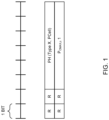
- Fig. 1 is a diagram illustrating one example of the PHR MAC CE according to NR.
- PH (a Type X or a PCell) in Fig. 1 indicates a 6-bit field, and indicates, for example, an index related to a Type X PH of a Primary Cell (PCell).
- the index related to the PH is associated with a specific PH level (dB).
- a Type 1 PH may be a PH in a case where a PUSCH is taken into account (e.g., only the PUSCH is taken into account).
- a Type 2 PH may be a PH in a case where a PUCCH is taken into account (e.g., the PUSCH and the PUCCH are taken into account).
- a Type 3 PH may be a PH in a case where a Sounding Reference Signal (SRS) is taken into account (e.g., the PUSCH and the SRS are taken into account).
- SRS Sounding Reference Signal
- NR supports a multiple entry PHR MAC CE, too, that resembles the above-described single entry (2 octets) and includes a plurality of items of data.
- Fig. 2 is a diagram illustrating one example of the multiple entry PHR MAC CE according to NR.
- R in Fig. 2 is a reservation field similar to that in Fig. 1 .
- a 6-bit field including a word "PH” in Fig. 2 indicates a PH field of a corresponding type and cell (a PCell, a Primary-Secondary Cell (PSCell), a PUCCH-SCell or an SCell).
- a 6-bit field including a word "P CMAX,c " in Fig. 2 is a P CMAX,c field that indicates P CMAX,c used for calculation of a last PH field.
- “C i " in Fig. 2 is a field that indicates whether or not a PH field of an SCell associated with an SCell index i is included in the PHR.
- the UE and/or the base station may determine (may switch and use) a step size of at least one of a PH and P CMAX,c reported by a PHR MAC CE based on at least one of followings:
- the maximum value of P CMAX,c may be maximum transmit power on the EIRP basis specified by 3GPP TS 38.101-2, or a value (e.g., a value obtained by adding a given offset value to the maximum transmit power) that is based on the maximum transmit power.
- the "band” may be read as a "Radio Access Technology (RAT)", a “carrier frequency”, a “Component Carrier (CC)”, a “frequency band”, a “frequency resource”, a “Bandwidth Part (BWP)”.
- RAT Radio Access Technology
- CC Component Carrier
- BWP Bandwidth Part
- the BWP may be referred to as a partial frequency band or a partial band.
- the step size of the PH may be determined (independently) without being based on P CMAX,c .
- a second threshold e.g. 10 dB
- a larger PH means smaller transmit power, and, even if the PH is roughly reported when the transmit power is small, an influence of an error of the PH is little (can be suitably controlled).
- the step size the first value (e.g., 1) may be determined.
- the step size the second value (e.g., 2) may be determined.
- the maximum value of P CMAX,c may be maximum transmit power of the UE power class specified by 3GPP TS 38.101, or a value (e.g., a value obtained by adding the given offset value to the maximum transmit power) based on the maximum transmit power.
- the UE capability may be read as a UE type.
- the UE type may include at least one of followings:
- the maximum transmit power configured to each CG may be, for example, a P-MCG related to an MCG or a P-SCG related to an SCG.
- the number of CGs is not limited to a case of 2 CGs, and, even when the number of CGs is 3 or more, the step sizes of P CMAX,c and/or the PH may be determined based on the parameter of the maximum transmit power configured per CG.
- the CG only needs to be a group related to one or more cells, and may be read as a PUCCH group or a Timing Advance Group (TAG).
- TAG Timing Advance Group
- the step sizes of both of P CMAX,c and the PH may be determined, or only one of the step sizes may be determined.
- the explicit notification may include information of the step sizes and/or a range, and may be notified to the UE by a higher layer signaling (e.g., an RRC signaling or an SIB), a physical layer signaling (e.g., DCI) or a combination of these signalings.
- the information of the step sizes may be notified as information that is respectively different between P CMAX,c and the PH, or may be notified as information that is common between P CMAX,c and the PH.
- the information of the step sizes and/or the range may be indicated by at least one unit of a CG unit, a node unit, a base station unit, a CC unit, a UL unit (e.g., a Supplementary Uplink (SUL) unit and/or a Non-Supplementary Uplink (Non-SUL) unit), a PH type unit and a BWP unit.
- a CG unit e.g., a Supplementary Uplink (SUL) unit and/or a Non-Supplementary Uplink (Non-SUL) unit
- SUL Supplementary Uplink
- Non-SUL Non-Supplementary Uplink
- the information of the step sizes and/or the range may be included in a CG configuration information element ( CellGroupConfig IE (Information Element)) of the RRC signaling, and configured per CG.
- the information of the step sizes and/or the range may be included in a BWP configuration information element ( BandwidthPart-Config IE ) of the RRC signaling, and configured per BWP.
- Default step sizes and/or range may be specified by a specification, or may be notified by a signaling (e.g., a higher layer signaling or a physical layer signaling).
- a signaling e.g., a higher layer signaling or a physical layer signaling.
- the UE may overwrite default values based on the information, or may use values indicated by the information instead of the default values.
- the above-described embodiment is not limited to application to a single entry PHR, and may be applied to other PHRs.
- the step size field may be configured by using one or a plurality of P, V and R fields in Fig. 2 .
- a step size and/or a range indicated for a specific cell may be used for other cells (e.g., PSCells, PUCCH-SCells or SCells).
- a PH and/or P CMAX,c may be determined based on two or more above-described (1) to (6). Taking, for example, above-described (2) and (4) into account, it may be determined to use a smaller (or larger) step size of a step size determined based on a band in use or a step size determined based on UE capability.
- a determination (switch) condition of the step size may be used to be read as a bit size of a PH field and/or a P CMAX,c field together with or instead of the step size and the range.
- sizes of the PH field and/or the P CMAX,c field may be switched between a plurality of bit sizes based on at least one of above-described (1) to (6).
- a plurality of these bit sizes may be 6, 7 and 8 bits.
- a plurality of these bit sizes may include the number of bits less than 6 bits, or may include the number of bits larger than 8 bits.
- these fields may not be contiguous fields.
- an R field immediately before P CMAX,c may be used to expand the PH field, or an R field immediately before the PH may be used to expand the P CMAX,c field.
- the step size and/or the range may be independently configured per cell, or may be independently configured per BWP (carrier f).
- the step size or the range is determined (switched) according to the above-embodiment.
- a table indicating an association between an index and the PH or P CMAX,c may be determined (may be switched) together with or instead of the step size or the range.
- This radio communication system uses one or a combination of the radio communication method according to each of the above embodiment of the present disclosure to perform communication.
- the user terminal 20 and the radio base station 11 can communicate by using a carrier (also referred to as a legacy carrier) of a narrow bandwidth in a relatively low frequency band (e.g., 2 GHz).
- a carrier also referred to as a legacy carrier
- the user terminal 20 and each radio base station 12 may use a carrier of a wide bandwidth in a relatively high frequency band (e.g., 3.5 GHz or 5 GHz) or may use the same carrier as that used between the user terminal 20 and the radio base station 11.
- a configuration of the frequency band used by each radio base station is not limited to this.
- the numerology may be a communication parameter to be applied to transmission and/or reception of a certain signal and/or channel, and may indicate at least one of, for example, a Sub-Carrier spacing (SCS), a bandwidth, a symbol length, a cyclic prefix length, a subframe length, a Transmission Time Interval (TTI) length (e.g., slot length), the number of symbols per TTI, a radio frame configuration, filtering processing and windowing processing.
- SCS Sub-Carrier spacing
- TTI Transmission Time Interval
- the radio base station 11 and each radio base station 12 are each connected with a higher station apparatus 30 and connected with a core network 40 via the higher station apparatus 30.
- the higher station apparatus 30 includes, for example, an access gateway apparatus, a Radio Network Controller (RNC) and a Mobility Management Entity (MME), yet is not limited to these.
- RNC Radio Network Controller
- MME Mobility Management Entity
- each radio base station 12 may be connected with the higher station apparatus 30 via the radio base station 11.
- Each user terminal 20 is a terminal that supports various communication schemes such as LTE and LTE-A, and may include not only a mobile communication terminal (mobile station) but also a fixed communication terminal (fixed station).
- the radio communication system 1 applies Orthogonal Frequency-Division Multiple Access (OFDMA) to downlink and applies Single Carrier-Frequency Division Multiple Access (SC-FDMA) and/or OFDMA to uplink as radio access schemes.
- OFDMA Orthogonal Frequency-Division Multiple Access
- SC-FDMA Single Carrier-Frequency Division Multiple Access
- OFDMA Orthogonal Frequency-Division Multiple Access
- the radio communication system 1 uses a downlink shared channel (PDSCH: Physical Downlink Shared Channel) shared by each user terminal 20, a broadcast channel (PBCH: Physical Broadcast Channel) and a downlink L1/L2 control channel as downlink channels.
- PDSCH Physical Downlink Shared Channel
- PBCH Physical Broadcast Channel
- SIB System Information Block
- MIB Master Information Block
- the downlink L1/L2 control channel includes a Physical Downlink Control Channel (PDCCH), an Enhanced Physical Downlink Control Channel (EPDCCH), a Physical Control Format Indicator Channel (PCFICH), and a Physical Hybrid-ARQ Indicator Channel (PHICH).
- DCI Downlink Control Information including scheduling information of the PDSCH and/or the PUSCH is conveyed on the PDCCH.
- the radio communication system 1 conveys a Cell-specific Reference Signal (CRS), a Channel State Information-Reference Signal (CSI-RS), a DeModulation Reference Signal (DMRS) and a Positioning Reference Signal (PRS) as downlink reference signals. Furthermore, the radio communication system 1 conveys a Sounding Reference Signal (SRS) and a DeModulation Reference Signal (DMRS) as uplink reference signals.
- the DMRS may be referred to as a user terminal-specific reference signal (UE-specific reference signal).
- a reference signal to be conveyed is not limited to these.
- User data transmitted from the radio base station 10 to the user terminal 20 on downlink is input from the higher station apparatus 30 to the baseband signal processing section 104 via the channel interface 106.
- the baseband signal processing section 104 performs processing of a Packet Data Convergence Protocol (PDCP) layer, segmentation and concatenation of the user data, transmission processing of a Radio Link Control (RLC) layer such as RLC retransmission control, Medium Access Control (MAC) retransmission control (e.g., HARQ transmission processing), and transmission processing such as scheduling, transmission format selection, channel coding, Inverse Fast Fourier Transform (IFFT) processing, and precoding processing on the user data, and transfers the user data to each transmitting/receiving section 103. Furthermore, the baseband signal processing section 104 performs transmission processing such as channel coding and inverse fast Fourier transform on a downlink control signal, too, and transfers the downlink control signal to each transmitting/receiving section 103.
- PDCP Packet Data Convergence Protocol
- RLC Radio Link Control
- MAC Medium Access Control
- MAC Medium Access Control
- HARQ transmission processing transmission processing
- transmission processing such as scheduling, transmission format selection,
- Each transmitting/receiving section 103 converts a baseband signal precoded and output per antenna from the baseband signal processing section 104 into a radio frequency range, and transmits a radio frequency signal.
- the radio frequency signal subjected to frequency conversion by each transmitting/receiving section 103 is amplified by each amplifying section 102, and is transmitted from each transmitting/receiving antenna 101.
- the transmitting/receiving sections 103 can be composed of transmitters/receivers, transmitting/receiving circuits or transmitting/receiving apparatuses described based on a common knowledge in a technical field according to the present disclosure.
- the transmitting/receiving sections 103 may be composed as an integrated transmitting/receiving section or may be composed of transmitting sections and reception sections.
- each amplifying section 102 amplifies a radio frequency signal received by each transmitting/receiving antenna 101 as an uplink signal.
- Each transmitting/receiving section 103 receives the uplink signal amplified by each amplifying section 102.
- Each transmitting/receiving section 103 performs frequency conversion on the received signal into a baseband signal, and outputs the baseband signal to the baseband signal processing section 104.
- the baseband signal processing section 104 performs Fast Fourier Transform (FFT) processing, Inverse Discrete Fourier Transform (IDFT) processing, error correcting decoding, MAC retransmission control reception processing, and reception processing of an RLC layer and a PDCP layer on user data included in the input uplink signal, and transfers the user data to the higher station apparatus 30 via the channel interface 106.
- the call processing section 105 performs call processing (such as a configuration and release) of a communication channel, state management of the radio base station 10 and radio resource management.
- the channel interface 106 transmits and receives signals to and from the higher station apparatus 30 via a given interface. Furthermore, the channel interface 106 may transmit and receive (backhaul signaling) signals to and from the another radio base station 10 via an inter-base station interface (e.g., optical fibers compliant with the Common Public Radio Interface (CPRI) or the X2 interface).
- an inter-base station interface e.g., optical fibers compliant with the Common Public Radio Interface (CPRI) or the X2 interface.
- each transmitting/receiving section 103 may further include an analog beam forming section that performs analog beam forming.
- the analog beam forming section can be composed of an analog beam forming circuit (e.g., a phase shifter or a phase shift circuit) or an analog beam forming apparatus (e.g., a phase shifter) described based on the common knowledge in the technical field according to the present disclosure.
- each transmitting/receiving antenna 101 may be composed of an array antenna, for example.
- Each transmitting/receiving section 103 may receive a PHR. Each transmitting/receiving section 103 may transmit information related to a step size and/or a range, and a TPC command to the user terminal 20.
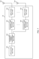
- Fig. 6 is a diagram illustrating one example of a function configuration of the radio base station according to the one embodiment.
- this example mainly illustrates function blocks of characteristic portions according to the present embodiment, and assumes that the radio base station 10 includes other function blocks, too, that are necessary for radio communication.
- the baseband signal processing section 104 includes at least a control section (scheduler) 301, a transmission signal generating section 302, a mapping section 303, a received signal processing section 304 and a measurement section 305.
- these components only need to be included in the radio base station 10, and part or all of the components may not be included in the baseband signal processing section 104.
- the control section (scheduler) 301 controls the entire radio base station 10.
- the control section 301 can be composed of a controller, a control circuit or a control apparatus described based on the common knowledge in the technical field according to the present disclosure.
- the control section 301 controls, for example, signal generation of the transmission signal generating section 302 and signal allocation of the mapping section 303. Furthermore, the control section 301 controls signal reception processing of the received signal processing section 304 and signal measurement of the measurement section 305.
- the control section 301 controls scheduling (e.g., resource allocation) of system information, a downlink data signal (e.g., a signal that is transmitted on the PDSCH), and a downlink control signal (e.g., a signal that is transmitted on the PDCCH and/or the EPDCCH and is, for example, transmission acknowledgement information). Furthermore, the control section 301 controls generation of a downlink control signal and a downlink data signal based on a result obtained by deciding whether or not it is necessary to perform retransmission control on an uplink data signal.
- scheduling e.g., resource allocation
- a downlink data signal e.g., a signal that is transmitted on the PDSCH
- a downlink control signal e.g., a signal that is transmitted on the PDCCH and/or the EPDCCH and is, for example, transmission acknowledgement information.
- the control section 301 controls generation of a downlink control signal and a downlink data signal based on a result obtained by deciding whether or not
- control section 301 controls scheduling of synchronization signals (e.g., a Primary Synchronization Signal (PSS)/a Secondary Synchronization Signal (SSS)) and downlink reference signals (e.g., a CRS, a CSI-RS and a DMRS).
- synchronization signals e.g., a Primary Synchronization Signal (PSS)/a Secondary Synchronization Signal (SSS)
- SSS Secondary Synchronization Signal
- downlink reference signals e.g., a CRS, a CSI-RS and a DMRS.
- the control section 301 may determine a step size of a value of a PH per increase of an index related to the PH (PH field), or a range of a value of the PH associated with the index based on a given condition.
- the control section 301 may determine a step size of a value of P CMAX,c per increase of an index related to P CMAX,c (P CMAX,c field), or a range of the value of P CMAX,c associated with the index based on a given condition.
- These given conditions may be determination conditions described in (1) to (6) of the above-described embodiment.
- the transmission signal generating section 302 generates a downlink signal (such as a downlink control signal, a downlink data signal or a downlink reference signal) based on an instruction from the control section 301, and outputs the downlink signal to the mapping section 303.
- the transmission signal generating section 302 can be composed of a signal generator, a signal generating circuit or a signal generating apparatus described based on the common knowledge in the technical field according to the present disclosure.
- the transmission signal generating section 302 generates, for example, a DL assignment for giving notification of downlink data allocation information, and/or a UL grant for giving notification of uplink data allocation information based on the instruction from the control section 301.
- the DL assignment and the UL grant are both DCI, and conform to a DCI format.
- the transmission signal generating section 302 performs encoding processing and modulation processing on the downlink data signal according to a code rate and a modulation scheme determined based on Channel State Information (CSI) from each user terminal 20.
- CSI Channel State Information
- the mapping section 303 maps the downlink signal generated by the transmission signal generating section 302, on given radio resources based on the instruction from the control section 301, and outputs the downlink signal to each transmitting/receiving section 103.
- the mapping section 303 can be composed of a mapper, a mapping circuit or a mapping apparatus described based on the common knowledge in the technical field according to the present disclosure.
- the received signal processing section 304 performs reception processing (e.g., demapping, demodulation and decoding) on a received signal input from each transmitting/receiving section 103.
- the received signal is, for example, an uplink signal (such as an uplink control signal, an uplink data signal or an uplink reference signal) transmitted from the user terminal 20.
- the received signal processing section 304 can be composed of a signal processor, a signal processing circuit or a signal processing apparatus described based on the common knowledge in the technical field according to the present disclosure.
- the received signal processing section 304 outputs information decoded by the reception processing to the control section 301.
- the received signal processing section 304 outputs the HARQ-ACK to the control section 301.
- the received signal processing section 304 outputs the received signal and/or the signal after the reception processing to the measurement section 305.
- the measurement section 305 performs measurement related to the received signal.
- the measurement section 305 can be composed of a measurement instrument, a measurement circuit or a measurement apparatus described based on the common knowledge in the technical field according to the present disclosure.
- the measurement section 305 may perform Radio Resource Management (RRM) measurement or Channel State Information (CSI) measurement based on the received signal.
- the measurement section 305 may measure received power (e.g., Reference Signal Received Power (RSRP)), received quality (e.g., Reference Signal Received Quality (RSRQ), a Signal to Interference plus Noise Ratio (SINR) or a Signal to Noise Ratio (SNR)), a signal strength (e.g., a Received Signal Strength Indicator (RSSI)) or channel information (e.g., CSI).
- RSRP Reference Signal Received Power
- RSSQ Reference Signal Received Quality
- SINR Signal to Noise Ratio
- the measurement section 305 may output a measurement result to the control section 301.
- the baseband signal processing section 204 of the user terminal 20 includes at least a control section 401, a transmission signal generating section 402, a mapping section 403, a received signal processing section 404 and a measurement section 405.
- these components only need to be included in the user terminal 20, and part or all of the components may not be included in the baseband signal processing section 204.
- the control section 401 may calculate a Power Headroom (PH) associated with a given uplink signal.
- PH Power Headroom
- the control section 401 may determine a step size of a value of a PH per increase of an index related to the PH (PH field), or a range of a value of the PH associated with the index based on a given condition.
- the control section 401 may determine a step size of a value of P CMAX,c per increase of an index related to P CMAX,c (P CMAX,c field), or a range of the value of P CMAX,c associated with the index based on a given condition.
- These given conditions may be determination conditions described in (1) to (6) of the above-described embodiment. In this regard, “determine” may be read as "assume”.
- the control section 401 may perform control for transmitting a Power Headroom Report (PHR) including the above-described index.
- PHR Power Headroom Report
- control section 401 may determine the above step size or range based on a specific bit of a PHR MAC CE used for transmission of the above PHR.
- the control section 401 may determine the above step size or range based on a band used by each transmitting/receiving section 203.
- the control section 401 may determine the above step size or range based on the value of P CMAX,c associated with the PH field (the value of P CMAX,c indicated by the P CMAX,c field).
- the control section 401 may determine the above step size or range based on capability of the user terminal.
- the control section 401 may determine the above step size or range based on maximum transmit power of each cell group configured to the user terminal.
- the control section 401 may determine the above step size or range based on an explicit signaling from the radio base station 10.
- control section 401 may update parameters used for control based on the various pieces of information.
- the transmission signal generating section 402 generates an uplink signal (such as an uplink control signal, an uplink data signal or an uplink reference signal) based on an instruction from the control section 401, and outputs the uplink signal to the mapping section 403.
- the transmission signal generating section 402 can be composed of a signal generator, a signal generating circuit or a signal generating apparatus described based on the common knowledge in the technical field according to the present disclosure.
- the transmission signal generating section 402 generates, for example, an uplink control signal related to transmission acknowledgement information and Channel State Information (CSI) based on the instruction from the control section 401. Furthermore, the transmission signal generating section 402 generates an uplink data signal based on the instruction from the control section 401.
- the transmission signal generating section 402 is instructed by the control section 401 to generate an uplink data signal.
- the mapping section 403 maps the uplink signal generated by the transmission signal generating section 402, on radio resources based on the instruction from the control section 401, and outputs the uplink signal to each transmitting/receiving section 203.
- the mapping section 403 can be composed of a mapper, a mapping circuit or a mapping apparatus described based on the common knowledge in the technical field according to the present disclosure.
- the received signal processing section 404 performs reception processing (e.g., demapping, demodulation and decoding) on the received signal input from each transmitting/receiving section 203.
- the received signal is, for example, a downlink signal (such as a downlink control signal, a downlink data signal or a downlink reference signal) transmitted from the radio base station 10.
- the received signal processing section 404 can be composed of a signal processor, a signal processing circuit or a signal processing apparatus described based on the common knowledge in the technical field according to the present disclosure. Furthermore, the received signal processing section 404 can compose the reception section according to the present disclosure.
- the received signal processing section 404 outputs information decoded by the reception processing to the control section 401.
- the received signal processing section 404 outputs, for example, broadcast information, system information, an RRC signaling and DCI to the control section 401. Furthermore, the received signal processing section 404 outputs the received signal and/or the signal after the reception processing to the measurement section 405.
- the measurement section 405 may perform RRM measurement or CSI measurement based on the received signal.
- the measurement section 405 may measure received power (e.g., RSRP), received quality (e.g., RSRQ, an SINR or an SNR), a signal strength (e.g., RSSI) or channel information (e.g., CSI).
- the measurement section 405 may output a measurement result to the control section 401.
Landscapes
- Engineering & Computer Science (AREA)
- Signal Processing (AREA)
- Computer Networks & Wireless Communication (AREA)
- Mobile Radio Communication Systems (AREA)
- Transmitters (AREA)
Claims (4)
- Endgerät (20), umfassend:einen Steuerungsabschnitt (401), der so konfiguriert ist, dass er auf der Grundlage eines Schwellenwerts eines Werts einer Leistungsreserve, PH, eine Schrittweite des Werts von PH pro Anstieg eines Index bestimmt, der sich auf den PH bezieht; undeinen Sendeabschnitt (203), der so konfiguriert ist, dass er einen Leistungsreservebericht, PHR, sendet, einschließlich des Index;wobei die Schrittweite einen ersten Wert und einen zweiten Wert einschließt, wobei der erste Wert eins ist und der zweite Wert zwei ist, undein Wert eines PH, der dem Index zugeordnet ist, durch den die Schrittweite als der zweite Wert bestimmt wird, größer ist als ein Wert eines PH, der dem Index zugeordnet ist, durch den die Schrittweite als der erste Wert bestimmt wird.
- Endgerät (20) nach Anspruch 1, wobei der Sendeabschnitt (203) so konfiguriert ist, dass er einen Index sendet, der sich auf die maximale Sendeleistung bezieht, und die Schrittweite unabhängig von der maximalen Sendeleistung bestimmt wird.
- Funkkommunikationsverfahren für ein Endgerät (20), umfassend:Bestimmen, basierend auf einem Schwellenwert einer Leistungsreserve, PH, einer Schrittweite des Werts PH pro Erhöhung eines Index, der sich auf den PH bezieht; undSenden eines Leistungsreserveberichts, PHR, einschließlich des Index;wobei die Schrittweite einen ersten Wert und einen zweiten Wert einschließt, wobei der erste Wert eins ist und der zweite Wert zwei ist, undein Wert von PH, der dem Index zugeordnet ist, durch den die Schrittgröße als der zweite Wert bestimmt wird, größer ist als ein Wert von PH, der dem Index zugeordnet ist, durch den die Schrittgröße als der erste Wert bestimmt wird.
- System, umfassend ein Endgerät (20) und eine Basisstation (10), wobeidas Endgerät (20) Folgendes umfasst:einen Steuerungsabschnitt (401), der so konfiguriert ist, dass er auf der Grundlage eines Schwellenwerts eines Werts einer Leistungsreserve, PH, eine Schrittweite des Werts von PH pro Anstieg eines dem PH zugeordneten Index bestimmt; undeinen Sendeabschnitt (203), der so konfiguriert ist, dass er einen Leistungsreservebericht, PHR, sendet, einschließlich des Index; unddie Basisstation (10) einen Empfangsabschnitt (103) umfasst, der zum Empfangen des PHR konfiguriert ist;wobei die Schrittweite einen ersten Wert und einen zweiten Wert einschließt, wobei der erste Wert eins ist und der zweite Wert zwei ist, undein Wert von PH, der dem Index zugeordnet ist, durch den die Schrittgröße als der zweite Wert bestimmt wird, größer ist als ein Wert von PH, der dem Index zugeordnet ist, durch den die Schrittgröße als der erste Wert bestimmt wird.
Applications Claiming Priority (1)
| Application Number | Priority Date | Filing Date | Title |
|---|---|---|---|
| PCT/JP2018/004730 WO2019155636A1 (ja) | 2018-02-09 | 2018-02-09 | ユーザ端末 |
Publications (3)
| Publication Number | Publication Date |
|---|---|
| EP3751913A1 EP3751913A1 (de) | 2020-12-16 |
| EP3751913A4 EP3751913A4 (de) | 2021-08-18 |
| EP3751913B1 true EP3751913B1 (de) | 2025-07-09 |
Family
ID=67548250
Family Applications (1)
| Application Number | Title | Priority Date | Filing Date |
|---|---|---|---|
| EP18904840.8A Active EP3751913B1 (de) | 2018-02-09 | 2018-02-09 | Benutzerausrüstung |
Country Status (6)
| Country | Link |
|---|---|
| US (1) | US20200367180A1 (de) |
| EP (1) | EP3751913B1 (de) |
| JP (1) | JP7053681B2 (de) |
| CN (1) | CN112166629B (de) |
| DK (1) | DK3751913T3 (de) |
| WO (1) | WO2019155636A1 (de) |
Families Citing this family (5)
| Publication number | Priority date | Publication date | Assignee | Title |
|---|---|---|---|---|
| CA3062807A1 (en) * | 2017-05-02 | 2019-11-28 | Guangdong Oppo Mobile Telecommunications Corp., Ltd. | Method for transmitting signal, network device and terminal device |
| CN114557054B (zh) * | 2019-10-02 | 2024-03-15 | 株式会社Ntt都科摩 | 终端、通信方法以及无线通信系统 |
| CN115002887B (zh) * | 2019-11-08 | 2024-01-16 | Oppo广东移动通信有限公司 | 功率余量上报方法及其装置 |
| US11672016B2 (en) * | 2019-12-09 | 2023-06-06 | Qualcomm Incorporated | RACH configuration for different power classes |
| US20240155511A1 (en) * | 2022-02-14 | 2024-05-09 | Lg Electronics Inc. | Method and apparatus for transmitting or receiving power headroom information in wireless communication system |
Citations (1)
| Publication number | Priority date | Publication date | Assignee | Title |
|---|---|---|---|---|
| EP3711382A1 (de) * | 2017-11-16 | 2020-09-23 | Telefonaktiebolaget LM Ericsson (Publ) | Leistungsreservenbetrieb für ergänzende uplink-träger |
Family Cites Families (11)
| Publication number | Priority date | Publication date | Assignee | Title |
|---|---|---|---|---|
| KR20110137446A (ko) * | 2010-06-17 | 2011-12-23 | 주식회사 팬택 | 다중 요소 반송파 시스템에서 전력정보의 전송장치 및 방법 |
| US8954106B2 (en) * | 2010-08-10 | 2015-02-10 | Samsung Electronics Co., Ltd. | Method and apparatus for configuring power headroom information in mobile communication system supporting carrier aggregation |
| US9615336B2 (en) | 2013-05-23 | 2017-04-04 | Qualcomm Incorporated | Uplink power headroom management for connectivity with logically separate cells |
| EP3001720B1 (de) * | 2013-05-23 | 2018-02-28 | LG Electronics Inc. | Verfahren zur übertragung eines leistungsreserveberichts in einem netzwerk mit unterstützung von vernetzung zwischen mehreren kommunikationssystemen und vorrichtung dafür |
| JP6298329B2 (ja) * | 2014-03-20 | 2018-03-20 | 株式会社Nttドコモ | ユーザ端末、無線基地局および無線通信方法 |
| US9357510B2 (en) * | 2014-03-31 | 2016-05-31 | Qualcomm Incorporated | Power sharing and power headroom reporting in dual connectivity scenarios |
| JP6490224B2 (ja) | 2014-12-22 | 2019-03-27 | ノキア ソリューションズ アンド ネットワークス オサケユキチュア | 送信の制御 |
| JPWO2016158535A1 (ja) * | 2015-03-31 | 2018-01-25 | 株式会社Nttドコモ | ユーザ端末、無線基地局及び無線通信方法 |
| US10412690B2 (en) | 2015-07-10 | 2019-09-10 | Qualcomm Incorporated | Power headroom reporting for low cost machine type communication |
| JP6153574B2 (ja) * | 2015-08-13 | 2017-06-28 | 株式会社Nttドコモ | ユーザ端末、無線基地局及び無線通信方法 |
| PL3473037T3 (pl) * | 2016-06-21 | 2020-07-13 | Telefonaktiebolaget Lm Ericsson (Publ) | Systemy i sposoby wyznaczania konfiguracji raportującej związanej z poziomem zasięgu urządzenia bezprzewodowego |
-
2018
- 2018-02-09 EP EP18904840.8A patent/EP3751913B1/de active Active
- 2018-02-09 CN CN201880092233.5A patent/CN112166629B/zh active Active
- 2018-02-09 WO PCT/JP2018/004730 patent/WO2019155636A1/ja not_active Ceased
- 2018-02-09 JP JP2019570265A patent/JP7053681B2/ja active Active
- 2018-02-09 DK DK18904840.8T patent/DK3751913T3/da active
- 2018-02-09 US US16/967,984 patent/US20200367180A1/en not_active Abandoned
Patent Citations (1)
| Publication number | Priority date | Publication date | Assignee | Title |
|---|---|---|---|---|
| EP3711382A1 (de) * | 2017-11-16 | 2020-09-23 | Telefonaktiebolaget LM Ericsson (Publ) | Leistungsreservenbetrieb für ergänzende uplink-träger |
Also Published As
| Publication number | Publication date |
|---|---|
| EP3751913A4 (de) | 2021-08-18 |
| CN112166629A (zh) | 2021-01-01 |
| DK3751913T3 (da) | 2025-08-18 |
| CN112166629B (zh) | 2024-03-12 |
| JP7053681B2 (ja) | 2022-04-12 |
| JPWO2019155636A1 (ja) | 2021-01-28 |
| WO2019155636A8 (ja) | 2020-12-03 |
| EP3751913A1 (de) | 2020-12-16 |
| US20200367180A1 (en) | 2020-11-19 |
| WO2019155636A1 (ja) | 2019-08-15 |
Similar Documents
| Publication | Publication Date | Title |
|---|---|---|
| US11496344B2 (en) | Terminal, radio communication method, base station, and system to communicate using hybrid automatic repeat request acknowledgement | |
| US11388686B2 (en) | User terminal and radio communication method | |
| EP3742833B1 (de) | Benutzerendgerät, drahtloskommunikationsverfahren, basisstation und system | |
| US11991700B2 (en) | User terminal and radio communication method | |
| US11330528B2 (en) | Terminal and radio communication method using a plurality of waveforms | |
| US11218995B2 (en) | User terminal, radio base station and radio communication method | |
| US11671921B2 (en) | Apparatus and system | |
| EP3713099A1 (de) | Benutzerendgerät und drahtloskommunikationsverfahren | |
| EP3706458A1 (de) | Benutzergerät und drahtloskommunikationsverfahren | |
| EP3737177A1 (de) | Benutzerendgerät und drahtloskommunikationsverfahren | |
| US12041472B2 (en) | User terminal and radio communication method | |
| US20210120506A1 (en) | User terminal and radio communication method | |
| EP3691387B1 (de) | Benutzerendgerät und funkkommunikationsverfahren | |
| WO2019193731A1 (ja) | ユーザ端末及び無線基地局 | |
| EP3737058A1 (de) | Benutzerendgerät und drahtloskommunikationsverfahren | |
| EP3668032A1 (de) | Benutzerendgerät und funkkommunikationsverfahren | |
| EP3751913B1 (de) | Benutzerausrüstung | |
| JPWO2019193733A1 (ja) | ユーザ端末及び無線基地局 | |
| US11563532B2 (en) | User terminal and radio communication method | |
| US11751226B2 (en) | User terminal and radio communication method | |
| US11502799B2 (en) | Terminal, radio communication method, and base station | |
| EP3664552B1 (de) | Endgerät, funkkommunikationsverfahren, basisstation und system | |
| HK40036635A (en) | User terminal and wireless communication method |
Legal Events
| Date | Code | Title | Description |
|---|---|---|---|
| STAA | Information on the status of an ep patent application or granted ep patent |
Free format text: STATUS: THE INTERNATIONAL PUBLICATION HAS BEEN MADE |
|
| PUAI | Public reference made under article 153(3) epc to a published international application that has entered the european phase |
Free format text: ORIGINAL CODE: 0009012 |
|
| STAA | Information on the status of an ep patent application or granted ep patent |
Free format text: STATUS: REQUEST FOR EXAMINATION WAS MADE |
|
| 17P | Request for examination filed |
Effective date: 20200826 |
|
| AK | Designated contracting states |
Kind code of ref document: A1 Designated state(s): AL AT BE BG CH CY CZ DE DK EE ES FI FR GB GR HR HU IE IS IT LI LT LU LV MC MK MT NL NO PL PT RO RS SE SI SK SM TR |
|
| AX | Request for extension of the european patent |
Extension state: BA ME |
|
| RAP1 | Party data changed (applicant data changed or rights of an application transferred) |
Owner name: NTT DOCOMO, INC. |
|
| DAV | Request for validation of the european patent (deleted) | ||
| DAX | Request for extension of the european patent (deleted) | ||
| A4 | Supplementary search report drawn up and despatched |
Effective date: 20210719 |
|
| RIC1 | Information provided on ipc code assigned before grant |
Ipc: H04W 52/06 20090101AFI20210713BHEP Ipc: H04W 52/36 20090101ALI20210713BHEP Ipc: H04L 5/00 20060101ALI20210713BHEP Ipc: H04W 52/34 20090101ALI20210713BHEP |
|
| STAA | Information on the status of an ep patent application or granted ep patent |
Free format text: STATUS: EXAMINATION IS IN PROGRESS |
|
| 17Q | First examination report despatched |
Effective date: 20221026 |
|
| P01 | Opt-out of the competence of the unified patent court (upc) registered |
Effective date: 20230509 |
|
| GRAP | Despatch of communication of intention to grant a patent |
Free format text: ORIGINAL CODE: EPIDOSNIGR1 |
|
| STAA | Information on the status of an ep patent application or granted ep patent |
Free format text: STATUS: GRANT OF PATENT IS INTENDED |
|
| RIC1 | Information provided on ipc code assigned before grant |
Ipc: H04W 88/02 20090101ALI20250324BHEP Ipc: H04W 52/36 20090101ALI20250324BHEP Ipc: H04L 5/00 20060101ALI20250324BHEP Ipc: H04W 52/34 20090101ALI20250324BHEP Ipc: H04W 52/06 20090101AFI20250324BHEP |
|
| INTG | Intention to grant announced |
Effective date: 20250404 |
|
| GRAS | Grant fee paid |
Free format text: ORIGINAL CODE: EPIDOSNIGR3 |
|
| GRAA | (expected) grant |
Free format text: ORIGINAL CODE: 0009210 |
|
| STAA | Information on the status of an ep patent application or granted ep patent |
Free format text: STATUS: THE PATENT HAS BEEN GRANTED |
|
| AK | Designated contracting states |
Kind code of ref document: B1 Designated state(s): AL AT BE BG CH CY CZ DE DK EE ES FI FR GB GR HR HU IE IS IT LI LT LU LV MC MK MT NL NO PL PT RO RS SE SI SK SM TR |
|
| REG | Reference to a national code |
Ref country code: GB Ref legal event code: FG4D |
|
| REG | Reference to a national code |
Ref country code: CH Ref legal event code: EP |
|
| REG | Reference to a national code |
Ref country code: IE Ref legal event code: FG4D |
|
| REG | Reference to a national code |
Ref country code: DE Ref legal event code: R096 Ref document number: 602018083512 Country of ref document: DE |
|
| REG | Reference to a national code |
Ref country code: DK Ref legal event code: T3 Effective date: 20250807 |
|
| REG | Reference to a national code |
Ref country code: SE Ref legal event code: TRGR |
|
| REG | Reference to a national code |
Ref country code: NL Ref legal event code: MP Effective date: 20250709 |
|
| PG25 | Lapsed in a contracting state [announced via postgrant information from national office to epo] |
Ref country code: PT Free format text: LAPSE BECAUSE OF FAILURE TO SUBMIT A TRANSLATION OF THE DESCRIPTION OR TO PAY THE FEE WITHIN THE PRESCRIBED TIME-LIMIT Effective date: 20251110 |
|
| PG25 | Lapsed in a contracting state [announced via postgrant information from national office to epo] |
Ref country code: NL Free format text: LAPSE BECAUSE OF FAILURE TO SUBMIT A TRANSLATION OF THE DESCRIPTION OR TO PAY THE FEE WITHIN THE PRESCRIBED TIME-LIMIT Effective date: 20250709 |
|
| REG | Reference to a national code |
Ref country code: AT Ref legal event code: MK05 Ref document number: 1813052 Country of ref document: AT Kind code of ref document: T Effective date: 20250709 |
|
| PG25 | Lapsed in a contracting state [announced via postgrant information from national office to epo] |
Ref country code: IS Free format text: LAPSE BECAUSE OF FAILURE TO SUBMIT A TRANSLATION OF THE DESCRIPTION OR TO PAY THE FEE WITHIN THE PRESCRIBED TIME-LIMIT Effective date: 20251109 |
|
| PG25 | Lapsed in a contracting state [announced via postgrant information from national office to epo] |
Ref country code: NO Free format text: LAPSE BECAUSE OF FAILURE TO SUBMIT A TRANSLATION OF THE DESCRIPTION OR TO PAY THE FEE WITHIN THE PRESCRIBED TIME-LIMIT Effective date: 20251009 |
|
| REG | Reference to a national code |
Ref country code: LT Ref legal event code: MG9D |
|
| PG25 | Lapsed in a contracting state [announced via postgrant information from national office to epo] |
Ref country code: AT Free format text: LAPSE BECAUSE OF FAILURE TO SUBMIT A TRANSLATION OF THE DESCRIPTION OR TO PAY THE FEE WITHIN THE PRESCRIBED TIME-LIMIT Effective date: 20250709 |
|
| PG25 | Lapsed in a contracting state [announced via postgrant information from national office to epo] |
Ref country code: FI Free format text: LAPSE BECAUSE OF FAILURE TO SUBMIT A TRANSLATION OF THE DESCRIPTION OR TO PAY THE FEE WITHIN THE PRESCRIBED TIME-LIMIT Effective date: 20250709 |
|
| PG25 | Lapsed in a contracting state [announced via postgrant information from national office to epo] |
Ref country code: HR Free format text: LAPSE BECAUSE OF FAILURE TO SUBMIT A TRANSLATION OF THE DESCRIPTION OR TO PAY THE FEE WITHIN THE PRESCRIBED TIME-LIMIT Effective date: 20250709 |
|
| PG25 | Lapsed in a contracting state [announced via postgrant information from national office to epo] |
Ref country code: GR Free format text: LAPSE BECAUSE OF FAILURE TO SUBMIT A TRANSLATION OF THE DESCRIPTION OR TO PAY THE FEE WITHIN THE PRESCRIBED TIME-LIMIT Effective date: 20251010 |
|
| PG25 | Lapsed in a contracting state [announced via postgrant information from national office to epo] |
Ref country code: LV Free format text: LAPSE BECAUSE OF FAILURE TO SUBMIT A TRANSLATION OF THE DESCRIPTION OR TO PAY THE FEE WITHIN THE PRESCRIBED TIME-LIMIT Effective date: 20250709 |
|
| PG25 | Lapsed in a contracting state [announced via postgrant information from national office to epo] |
Ref country code: BG Free format text: LAPSE BECAUSE OF FAILURE TO SUBMIT A TRANSLATION OF THE DESCRIPTION OR TO PAY THE FEE WITHIN THE PRESCRIBED TIME-LIMIT Effective date: 20250709 Ref country code: PL Free format text: LAPSE BECAUSE OF FAILURE TO SUBMIT A TRANSLATION OF THE DESCRIPTION OR TO PAY THE FEE WITHIN THE PRESCRIBED TIME-LIMIT Effective date: 20250709 |
|
| PG25 | Lapsed in a contracting state [announced via postgrant information from national office to epo] |
Ref country code: RS Free format text: LAPSE BECAUSE OF FAILURE TO SUBMIT A TRANSLATION OF THE DESCRIPTION OR TO PAY THE FEE WITHIN THE PRESCRIBED TIME-LIMIT Effective date: 20251009 |
|
| PG25 | Lapsed in a contracting state [announced via postgrant information from national office to epo] |
Ref country code: ES Free format text: LAPSE BECAUSE OF FAILURE TO SUBMIT A TRANSLATION OF THE DESCRIPTION OR TO PAY THE FEE WITHIN THE PRESCRIBED TIME-LIMIT Effective date: 20250709 |
|
| PG25 | Lapsed in a contracting state [announced via postgrant information from national office to epo] |
Ref country code: SM Free format text: LAPSE BECAUSE OF FAILURE TO SUBMIT A TRANSLATION OF THE DESCRIPTION OR TO PAY THE FEE WITHIN THE PRESCRIBED TIME-LIMIT Effective date: 20250709 |
|
| PGFP | Annual fee paid to national office [announced via postgrant information from national office to epo] |
Ref country code: SE Payment date: 20260223 Year of fee payment: 9 |
|
| PGFP | Annual fee paid to national office [announced via postgrant information from national office to epo] |
Ref country code: GB Payment date: 20260225 Year of fee payment: 9 |
|
| PGFP | Annual fee paid to national office [announced via postgrant information from national office to epo] |
Ref country code: DE Payment date: 20260225 Year of fee payment: 9 Ref country code: DK Payment date: 20260225 Year of fee payment: 9 |
|
| PG25 | Lapsed in a contracting state [announced via postgrant information from national office to epo] |
Ref country code: IT Free format text: LAPSE BECAUSE OF FAILURE TO SUBMIT A TRANSLATION OF THE DESCRIPTION OR TO PAY THE FEE WITHIN THE PRESCRIBED TIME-LIMIT Effective date: 20250709 |