EP3985397B1 - Automatische analysevorrichtung - Google Patents
Automatische analysevorrichtung Download PDFInfo
- Publication number
- EP3985397B1 EP3985397B1 EP20822662.1A EP20822662A EP3985397B1 EP 3985397 B1 EP3985397 B1 EP 3985397B1 EP 20822662 A EP20822662 A EP 20822662A EP 3985397 B1 EP3985397 B1 EP 3985397B1
- Authority
- EP
- European Patent Office
- Prior art keywords
- radiator
- air
- heat
- temperature
- airflow path
- Prior art date
- Legal status (The legal status is an assumption and is not a legal conclusion. Google has not performed a legal analysis and makes no representation as to the accuracy of the status listed.)
- Active
Links
Images



Classifications
-
- G—PHYSICS
- G01—MEASURING; TESTING
- G01N—INVESTIGATING OR ANALYSING MATERIALS BY DETERMINING THEIR CHEMICAL OR PHYSICAL PROPERTIES
- G01N35/00—Automatic analysis not limited to methods or materials provided for in any single one of groups G01N1/00 - G01N33/00; Handling materials therefor
- G01N35/00584—Control arrangements for automatic analysers
- G01N35/00594—Quality control, including calibration or testing of components of the analyser
- G01N35/00613—Quality control
- G01N35/00663—Quality control of consumables
-
- G—PHYSICS
- G01—MEASURING; TESTING
- G01N—INVESTIGATING OR ANALYSING MATERIALS BY DETERMINING THEIR CHEMICAL OR PHYSICAL PROPERTIES
- G01N35/00—Automatic analysis not limited to methods or materials provided for in any single one of groups G01N1/00 - G01N33/00; Handling materials therefor
-
- B—PERFORMING OPERATIONS; TRANSPORTING
- B01—PHYSICAL OR CHEMICAL PROCESSES OR APPARATUS IN GENERAL
- B01L—CHEMICAL OR PHYSICAL LABORATORY APPARATUS FOR GENERAL USE
- B01L7/00—Heating or cooling apparatus; Heat insulating devices
- B01L7/52—Heating or cooling apparatus; Heat insulating devices with provision for submitting samples to a predetermined sequence of different temperatures, e.g. for treating nucleic acid samples
-
- B—PERFORMING OPERATIONS; TRANSPORTING
- B01—PHYSICAL OR CHEMICAL PROCESSES OR APPARATUS IN GENERAL
- B01L—CHEMICAL OR PHYSICAL LABORATORY APPARATUS FOR GENERAL USE
- B01L2200/00—Solutions for specific problems relating to chemical or physical laboratory apparatus
- B01L2200/14—Process control and prevention of errors
- B01L2200/143—Quality control, feedback systems
- B01L2200/147—Employing temperature sensors
-
- B—PERFORMING OPERATIONS; TRANSPORTING
- B01—PHYSICAL OR CHEMICAL PROCESSES OR APPARATUS IN GENERAL
- B01L—CHEMICAL OR PHYSICAL LABORATORY APPARATUS FOR GENERAL USE
- B01L2300/00—Additional constructional details
- B01L2300/18—Means for temperature control
- B01L2300/1805—Conductive heating, heat from thermostatted solids is conducted to receptacles, e.g. heating plates, blocks
- B01L2300/1822—Conductive heating, heat from thermostatted solids is conducted to receptacles, e.g. heating plates, blocks using Peltier elements
-
- G—PHYSICS
- G01—MEASURING; TESTING
- G01N—INVESTIGATING OR ANALYSING MATERIALS BY DETERMINING THEIR CHEMICAL OR PHYSICAL PROPERTIES
- G01N35/00—Automatic analysis not limited to methods or materials provided for in any single one of groups G01N1/00 - G01N33/00; Handling materials therefor
- G01N2035/00346—Heating or cooling arrangements
-
- G—PHYSICS
- G01—MEASURING; TESTING
- G01N—INVESTIGATING OR ANALYSING MATERIALS BY DETERMINING THEIR CHEMICAL OR PHYSICAL PROPERTIES
- G01N35/00—Automatic analysis not limited to methods or materials provided for in any single one of groups G01N1/00 - G01N33/00; Handling materials therefor
- G01N2035/00346—Heating or cooling arrangements
- G01N2035/00356—Holding samples at elevated temperature (incubation)
- G01N2035/00386—Holding samples at elevated temperature (incubation) using fluid heat transfer medium
- G01N2035/00396—Holding samples at elevated temperature (incubation) using fluid heat transfer medium where the fluid is a liquid
-
- G—PHYSICS
- G01—MEASURING; TESTING
- G01N—INVESTIGATING OR ANALYSING MATERIALS BY DETERMINING THEIR CHEMICAL OR PHYSICAL PROPERTIES
- G01N35/00—Automatic analysis not limited to methods or materials provided for in any single one of groups G01N1/00 - G01N33/00; Handling materials therefor
- G01N2035/00346—Heating or cooling arrangements
- G01N2035/00435—Refrigerated reagent storage
-
- G—PHYSICS
- G01—MEASURING; TESTING
- G01N—INVESTIGATING OR ANALYSING MATERIALS BY DETERMINING THEIR CHEMICAL OR PHYSICAL PROPERTIES
- G01N35/00—Automatic analysis not limited to methods or materials provided for in any single one of groups G01N1/00 - G01N33/00; Handling materials therefor
- G01N2035/00346—Heating or cooling arrangements
- G01N2035/00445—Other cooling arrangements
-
- G—PHYSICS
- G01—MEASURING; TESTING
- G01N—INVESTIGATING OR ANALYSING MATERIALS BY DETERMINING THEIR CHEMICAL OR PHYSICAL PROPERTIES
- G01N35/00—Automatic analysis not limited to methods or materials provided for in any single one of groups G01N1/00 - G01N33/00; Handling materials therefor
- G01N35/00584—Control arrangements for automatic analysers
- G01N35/00594—Quality control, including calibration or testing of components of the analyser
- G01N35/00613—Quality control
- G01N35/00663—Quality control of consumables
- G01N2035/00673—Quality control of consumables of reagents
Definitions
- the present invention relates to an automatic analysis device, and more particularly, to an automatic analysis device including a mechanism for adjusting a temperature of a portion requiring temperature adjustment.
- Patent Document 1 describes that temperature of a heat transfer block is controlled intermittently, for example, the temperature of the heat transfer block is controlled based on opening and closing control of a replacement liquid electromagnetic valve.
- US2015/355061A1 proposes a sample cooling device capable of effectively removing moisture in the air inside an accommodating chamber where a sample container is accommodated, and of preventing a problem caused by occurrence of frost, an autosampler provided with the same, and a sample cooling method.
- the automatic analysis device is a device for optically measuring a reaction solution by dispensing a specimen solution containing an analysis target material and a reaction reagent into a reaction vessel and reacting the specimen solution with the reaction reagent.
- a specimen solution containing an analysis target material and a reaction reagent into a reaction vessel and reacting the specimen solution with the reaction reagent.
- specific biological components and chemical materials contained in biological specimens such as blood, serum, and urine are detected.
- Patent Document 1 As a method of adjusting the temperature of the reagent in the automatic analysis device, as in Patent Document 1, it is known that the temperature of the reagent in the pretreatment process of analysis is adjusted by the Peltier element, and the liquid that is intermittently flowed to cool or heat the Peltier element is used, thereby the temperature of the reagent can be stably adjusted regardless of a change in the outside air temperature.
- the temperature of the replacement liquid tank for storing the replacement liquid is adjusted by the Peltier element, but the temperature is controlled independently of the other portions that require being temperature-adjusted.
- An object of the present invention is to provide an automatic analysis device capable of temperature-controlling a plurality of portions requiring temperature control with less power consumption as a whole.
- the present invention provides an automatic analysis device according to claim 1.
- an automatic analysis device of the present invention is not particularly limited, and may be applied to various types of automatic analysis devices such as an automatic analysis device for immunological item analysis and an automatic analysis device for biochemical item analysis.
- Example 1 of the automatic analysis device of the present invention will be described with reference to Figs. 1 to 6 .
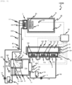
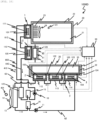
- Fig. 1 is a diagram illustrating the overall configuration of the automatic analysis device and the configuration of the temperature adjustment mechanism thereof of this Example.
- An automatic analysis device 1000 illustrated in Fig. 1 is a device for reacting a specimen with a reagent and measuring physical properties of the reacted reaction solution and includes an analysis unit 500.
- the analysis unit 500 may be configured with a mechanism other than the mechanisms described later among a mechanism for measuring the physical properties of the reaction solution, a mechanism for executing a treatment or a post-treatment of reacting a specimen with a reagent necessary for measuring the physical properties, and treatments associated with these various treatments, and can be configured to have a known configuration.
- known operations may also be used for those operations.
- the automatic analysis device 1000 illustrated in Fig. 1 further includes an air-conditioned space 20 for performing a processing operation and the like of the reagent to be analyzed by the analysis unit 500, a reagent storage unit 30 for keeping the reagent to be used cold, and a control device 50 for controlling the operation of each mechanism described later.
- the air-conditioned space 20 is partitioned from a surrounding space by an insulating material 22, and is air-conditioned so as to keep a temperature of an internal air 21 constant.
- the internal air 21 of the air-conditioned space 20 is circulated by a fan 25, and thus, the internal air is cooled or heated when passing through an internal fin 23 portion.
- the internal fin 23 is connected to a Peltier unit 1.
- the reagent storage unit 30 is a space for storing the reagent, and an internal space 31 thereof is maintained at a relatively low temperature (for example, 5 to 10°C) as compared with the air-conditioned space 20.
- the internal space 31 is surrounded by a metal container 32 made of stainless steel or the like, and the surrounding thereof is partitioned from the surrounding space by an insulating material 33.
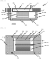
- Fig. 2 illustrates a cross section of the Peltier unit 1 which is a B-B' cross section of Fig. 3
- Fig. 3 illustrates a cross section of a heat sink portion of the Peltier unit 1 which is a A-A' cross section of Fig. 2
- a Peltier element 101 that adjusts the air temperature of the air-conditioned space 20 is incorporated into the Peltier unit 1 illustrated in Figs. 1 to 3 .
- the Peltier element 101 can switch a heat generating surface (a surface where the temperature is increased) and an endothermic surface (a surface where the temperature falls) of the Peltier element 101 depending on a direction of a current flowing by a power supply connected to a lead wire (not illustrated) thereof.
- An output of the Peltier element 101 is controlled by repeating operation and stop with a predetermined current and changing a ratio of an operation time, that is, an operating rate.
- a magnitude of the current applied to the Peltier element 101 may be directly changed.
- the operating rate and the current are controlled by the control device 50 of Fig. 1 based on a detection temperature of a sensor and a target temperature.
- the controlling of the operating rate and the current is performed by, for example, proportional-integral-differential control (PID control).
- the control device 50 can be realized by loading programs into a computer or a Field-Programmable Gate Array (FPGA) including a CPU, a memory, an interface, and the like and executing a calculation. These programs are stored in an internal recording medium or an external recording medium (not illustrated) in each configuration and are read and executed by the CPU.
- FPGA Field-Programmable Gate Array
- control process of the operation of each mechanism of the control device 50 may be integrated into one program, may be divided into a plurality of programs, or may be a combination thereof.
- a portion or all of the programs may be realized by dedicated hardware or may be modularized.
- various programs may be provided to each device from a program distribution server, an internal recording medium, or an external recording medium.
- a heat diffusion plate 203 made of aluminum or the like is provided via a thermal interface 202 such as grease on the surface (lower side in Fig. 2 , the air-conditioned space 20 side) of the Peltier element 101 of the side where the temperature control of a control object is performed.
- the heat diffusion plate 203 is connected to a temperature control object, that is, a base 24 of the internal fin 23 in Fig. 1 via a thermal interface 204 such as grease.
- a heat sink 111 is connected via a thermal interface 201 such as grease on the surface (upper side in Fig. 2 ) of the Peltier element 101 of the opposite side where the temperature control of the control object is performed.
- a thermal interface 201 such as grease on the surface (upper side in Fig. 2 ) of the Peltier element 101 of the opposite side where the temperature control of the control object is performed.
- the heat sink 111 is a member for cooling or heating the Peltier unit 1 with a liquid refrigerant (hereinafter, referred to as a circulating liquid).
- the heat diffusion plate 203, the Peltier element 101, and the heat sink 111 are fixed in a state of being in close contact with each other by fastening a bolt 207 to a hole 216.
- the heat diffusion plate 203 is surrounded by a resin thermal interface 204, an insulating material 205, and a space 206. It is noted that air can be used instead of the insulating material 205, and the insulating material can be disposed in the space 206.
- the Peltier element 101 of this Example is energized so that, when the temperature detected by a temperature sensor 121 in Fig. 1 is higher than the target temperature, the temperature of the surface of the side (the heat diffusion plate 203 in Fig. 2 , the side of the internal fin 23 in Fig. 1 ) of the control object is decreased, and the temperature of the surface of the side of the heat sink 111 on the opposite side is increased.
- the base 24 of the internal fins of Fig. 1 and the internal fins 23 are cooled via the thermal interface 202, the heat diffusion plate 203, and the thermal interface 204, and the air the inside of the air-conditioned space 20 guided to the internal fins 23 by the fan 25 is cooled.
- the side of the heat sink 111 of the Peltier element 101 is heated, and heat is dissipated to the circulating liquid flowing inside the heat sink 111 via the thermal interface 201 such as grease.
- the circulating liquid is a medium for carrying heat, and pure water, ethylene glycol aqueous solution, and the like are used.
- the circulating liquid is sent to the heat sink 111 of the Peltier unit 1 through a tube 60 by a pump 10.
- An arrow 410 in Fig. 1 indicates the direction in which the circulating liquid flows.
- the circulating liquid flowing through the tube 60 flows into the inside of the heat sink 111 from a tube connector 211 at the inlet of the heat sink 111, passes through the internal space partitioned by a partition 215, and flows out into a tube 61 from a tube connector 212.
- a plurality of flow paths 214 interposed between fins 213 are formed in the internal space of the heat sink 111, and the circulating liquid flows therebetween.
- This circulating liquid takes heat from the Peltier element 101 connected to a casing 210 of the heat sink via the thermal interface 201 or applies heat to the Peltier element 101.
- the fins 213 play a role in increasing the heat transfer area and improving the heat exchange performance.
- Aluminum, copper, or the like is used as the material of the casing 210 and the fins 213 of the heat sink 111.
- the circulating liquid heated by the heat sink 111 reaches a first radiator 12 which performs heat exchange between the circulating liquid that has exchanged heat with the heat sink 111 and the air in the atmosphere to be cooled by the air sent by a radiator fan 14 and is sucked into the pump 10 via a tank 15.
- the details of the first radiator 12 will be described in detail later with reference to Figs. 4 and 5 .
- the Peltier element 101 is energized in the opposite direction to be operated so that the internal fin 23 side is heated, and the heat sink 111 side is cooled.
- the circulating liquid cooled by the heat sink 111 reaches the first radiator 12, where the circulating liquid is heated by the air sent by the radiator fan 14. After that, the circulating liquid is sucked into the pump 10 via the tank 15 and sent to the heat sink 111 of the Peltier unit 1 through the tube 60 as described above.
- a first loop is formed by the tubes 60 and 61 connecting the heat sink 111, the first radiator 12, and the pump 10.
- Peltier units 2, 3, and 4 are connected to the metal container 32 constituting the reagent storage unit 30.
- the metal container 32 is cooled by energizing Peltier elements 102, 103, and 104 incorporated in the Peltier units 2, 3, and 4 in the direction in which the side of the metal container 32 is cooled, and the internal space 31 and the contents thereof are cooled.
- the circulating liquid for cooling and heating is sent to heat sinks 112, 113, and 114 of the Peltier units 2, 3, and 4 through a tube 62 by a pump 11.
- the Peltier elements 102, 103, and 104 are controlled by the control device 50 so that the temperature of temperature sensors 122, 123, and 124 becomes the target temperature.
- the Peltier element 102 is controlled so as to energize in the direction in which the temperature on the side of the metal container 32 is decreased.
- the Peltier element 102 is energized in the direction in which the temperature on the side of the metal container 32 is decreased, and when the temperature detected by the temperature sensor 124 is higher than the target temperature, the Peltier element 104 is energized in the direction in which the temperature on the side of the metal container 32 is decreased.
- the surfaces of the Peltier elements 102, 103, and 104 on the sides of the heat sinks 112, 113, and 114 generate heat, so that the temperature is increased, but the surfaces of the Peltier elements 102, 103, and 104 are cooled by the circulating liquid flowing through the heat sinks 112, 113, and 114.
- the circulating liquid flows from the pump 11 through the tube 62 in the order of the heat sink 114 of the Peltier unit 4, the heat sink 113 of the Peltier unit 3, and the heat sink 112 of the Peltier unit 2 to be heated and reaches a second radiator 13 through a tube 63.
- the circulating liquid is cooled by the air sent by the radiator fan 14, so that the temperature is decreased, and the liquid is sucked into the pump 11 via the tank 16 so as to be sent to the Peltier unit 4.
- a second loop is formed by the tubes 62 and 63 connecting the heat sinks 112, 113, and 114, the second radiator 13, and the pump 11 circulating the circulating liquid.
- the Peltier element 102 is controlled so as to be energized in the direction in which the temperature on the side of the metal container 32 is increased. At this time, the temperature of the Peltier element 102 on the heat sink 112 side is decreased, but the temperature of the Peltier element 102 is heated by the circulating liquid flowing through the heat sink 112.
- the Peltier element 103 is energized in the direction in which the temperature on the side of the metal container 32 is increased.
- the Peltier element 104 is energized in the direction in which the temperature on the side of the metal container 32 is increased.
- the surfaces of the Peltier elements 102, 103, and 104 on the heat sinks 112, 113, and 114 sides are cooled to be decreased in temperature, but the surfaces of the Peltier elements 102, 103, and 104 are heated by the circulating liquid flowing through the heat sinks 112, 113, and 114.
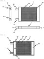
- Figs. 4A and 4B are views illustrating the overall structures of the first radiator 12 and the second radiator 13
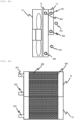
- Fig. 5 is a view illustrating the structure of the first radiator 12
- Fig. 6 is a view illustrating a A-A' cross section Fig. 5 .
- the first radiator 12 having a small front area and the second radiator 13 having a large front area are disposed side by side in the direction (in the direction of an arrow 401) in which the air is sent by the radiator fan 14.
- the first radiator 12 having a small area is on the upstream side and the second radiator 13 having a large area is on the downstream side, and the first radiator 12 and the second radiator 13 are disposed in series so as to perform heat exchange.
- an inlet connector 301 and an outlet connector 302 of the circulating liquid are provided to the first radiator 12, and an inlet connector 303 and an outlet connector 304 of the circulating liquid are provided to the second radiator 13.
- the first radiator 12 includes a flow path 305 through which the circulating liquid flows and fins 306 provided therebetween.
- the same also applies to the second radiator 13.
- Aluminum or the like is used as the material of the flow path 305 and the fin 306.
- Figs. 5 and 6 air flows between the fins 306 in a direction perpendicular to the paper surface.
- the circulating liquid flows in from the inlet connector 301, flows through each flow path 305 from a header 307, changes the direction of the flow at a turn unit 309, reaches an exit footer 308 from the flow path 305, and flows out from the outlet connector 302.
- the structure of the second radiator 13 is the same as that of the first radiator 12.
- the temperature detected by the temperature sensor 121 of the air-conditioned space 20 is lower than the target temperature, and the temperature detected by the temperature sensors 122, 123, and 124 of the reagent storage unit 30 becomes higher than the target temperature.
- the Peltier element 101 performs the operation of heating the side of the air-conditioned space 20, and the circulating liquid is cooled by the heat sink 111 and transported to the first radiator 12.
- the Peltier elements 102, 103, and 104 perform the operation of cooling the side of the reagent storage unit 30, and the circulating liquid of the heat sinks 112, 113, and 114 is heated and transported to the second radiator 13.
- the air cooled by passing through the first radiator 12 cools the second radiator 13 according to the arrangement relationship as illustrated in Fig. 5 and the like.
- the amount of heat dissipated from the second radiator 13 is increased by additionally cooling by the first radiator 12, and the Peltier elements 102, 103, and 104 can cool the reagent storage unit 30 with a smaller current, that is, a smaller power consumption.
- the temperature around the device is relatively high due to in the summer.
- the temperature detected by the temperature sensor 121 in the air-conditioned space 20 becomes higher than the target temperature.
- the circulating liquid is heated in the heat sink 111 to reach the first radiator 12, so that the air passing through the first radiator 12 is heated.
- the target temperature of the air-conditioned space 20 is lower than the target temperature of the reagent storage unit 30 and the cooling load is smaller than that of the reagent storage unit 30, the heating amount of the circulating liquid in the heat sink 111 is relatively small.
- the temperature increase of the air that has passed through the first radiator 12 is also relatively small.
- the front area of the first radiator 12 is smaller than the front area of the second radiator 13, the circulating liquid in the second radiator 13 can be sufficiently cooled, so that the cooling that is the same as in the related art can be realized.
- Fig. 7 is an overall configuration diagram of an automatic analysis device 1000A and a temperature adjustment mechanism thereof according to Example 2.
- Example 2 the same configurations as those in Example 1 are denoted by the same reference numerals, and the description thereof will be omitted. The same applies to the following examples.
- the analysis unit 500 is omitted for the convenience of illustration.
- the first radiator 12 and the second radiator 13 are disposed so as to perform heat exchange, but in the automatic analysis device 1000A of this Example, a first radiator 12A and a second radiator 13B are disposed so as not to perform heat exchange with the air but to perform heat exchange with the circulating liquid.
- a radiator fan 17 is disposed around the first radiator 12A, and the air is blown in the direction of an arrow 402.
- a radiator fan 14A is disposed around the second radiator 13, and the air is blown in the direction of the arrow 401.
- the loop of the circulating liquid in this Example is not the two loops as in Example 1 but one big loop formed by a tube 64A which guides the circulating liquid that has exchanged heat with the first radiator 12A to the heat sinks 112, 113, and 114, a tube 63A which guides the circulating liquid that has exchanged heat with the heat sinks 112, 113, and 114 to a second radiator 13A, a tube 65A which guides the circulating liquid that has exchanged heat with the second radiator 13A to the pump 10, and a tube 60A which guides the liquid from the pump 10 to the heat sink 111.
- one pump 10 and one tank 15 are provided, and the circulating liquid sent by the pump 10 passes through the tube 60A, and flows into the heat sink 111 of the Peltier unit 1 provided in the air-conditioned space 20.
- the circulating liquid flows into the first radiator 12 via a tube 61A, and after the heat exchange, the circulating liquid flows into the heat sink 114 of the Peltier unit 4 provided to the reagent storage unit 30 via the tube 64A.
- the circulating liquid flows into the second radiator 13 via the tube 63A via the heat sink 113 of the Peltier unit 3 and the heat sink 112 of the Peltier unit 2. After further heat exchange in the second radiator 13 is performed, the circulating liquid returns to the pump 10 from the tank 15 via the tube 65A.
- the temperature detected by the temperature sensor 121 of the air-conditioned space 20 is lower than the target temperature, and the temperature detected by the temperature sensors 122, 123, and 124 of the reagent storage unit 30 becomes higher than the target temperature.
- the circulating liquid is cooled in the heat sink 111 and transported to the first radiator 12A, but the radiator fan 17 of the first radiator 12A is stopped, and thus, the circulating liquid in a state where the circulating liquid is not so heated by the first radiator 12A is supplied to the heat sinks 112 of the Peltier units 2, 3, and 4.
- the circulating liquid cooled in the heat sink 111 can be directly supplied to the heat sinks 112, 113, and 114 of the Peltier units 2, 3, and 4, so that the Peltier units 2, 3, and 4 can be efficiently cooled, and thus, it is possible to realize the temperature control with lower power consumption.
- the temperature detected by the temperature sensor 121 in the air-conditioned space 20 becomes higher than the target temperature.
- the circulating liquid heated in the heat sink 111 reaches the first radiator 12A, and the circulating liquid cooled by the air blown by the radiator fan 17 is supplied to the heat sinks 112, 113, and 114 of the Peltier units 2, 3, and 4.
- the Peltier units 2, 3, and 4 can be more efficiently cooled than the case of simply cooling the Peltier units, and thus, it is possible to realize the temperature control with lower power consumption.
- the automatic analysis device 1000A of this Example can also realize the temperature control of the air-conditioned space 20 and the reagent storage unit 30 with less power consumption than the related art.
- Fig. 8 is a configurational diagram of the automatic analysis device and a temperature adjustment mechanism thereof according to Example 3.
- an automatic analysis device 1000B of this Example is provided with a duct 71 at an outlet of the second radiator 13B.
- the downstream portion of the duct 71 is divided into two flow paths 71B and 71C by a partition 75. It is noted that the upstream portion of the duct 71 constitutes a first airflow path 71A which guides the air that has exchanged heat with the second radiator 13B to the exhaust port or a first radiator 12B.
- the first radiator 12B is disposed on the one flow path 71B side, so that the air that has exchanged heat with the second radiator 13B passes through the first radiator 12B and is guided to the outside.
- a damper 72 that switches the air guided to the flow path 71B between the air from the flow path 71A and the air from an air inlet port 74 is provided on the flow path 71B side.
- the position of the damper 72 is controlled by the control device 50.
- the air inlet port 74 is provided at a position in front of the first radiator 12B of the flow path 71B and is an opening for guiding the air from the outside of the flow path 71B to the flow path 71B.
- the temperature detected by the temperature sensor 121 of the air-conditioned space 20 becomes lower than the target temperature, and the temperature detected by the temperature sensors 122, 123, and 124 of the reagent storage unit 30 becomes higher than the target temperature.
- the circulating liquid cooled in the heat sink 111 is transported to the first radiator 12B via the tube 60, and the circulating liquid heated in the heat sinks 112, 113, and 114 is transported to the second radiator 13B via the tube 63.
- the damper 72 of the duct 71 is set at the position A in Fig. 8 . Accordingly, as indicated by an arrow 405 illustrated in Fig. 8 , the air sucked into the second radiator 13B by a radiator fan 14B and the fan 73 is heated by exchanging heat with the circulating fluid, and after that, is distributed to the air passing through the first radiator 12B by the radiator fan 14B and the air directly exhausted by the fan 73.
- the heated circulating liquid is supplied to the heat sink 111, so that the power consumption of the Peltier element 101 for heating the air-conditioned space 20 can be reduced, and thus, energy-saving operation is realized.
- further power saving operation can be performed by appropriately adjusting the rotation speeds of the radiator fan 14B and the fan 73 to distribute the wind volume.
- the temperature detected by the temperature sensor 121 in the air-conditioned space 20 becomes higher than the target temperature.
- the circulating liquid heated by the heat sink 111 is sent to the first radiator 12B.
- the damper 72 is set to the position B.
- the air supplied to the first radiator 12B is supplied from the outside of the duct 71 through the air inlet port 74 as illustrated by an arrow 406 of the broken line illustrated in Fig. 8 .
- all the air heated by heat that has exchanged in the second radiator 13B is exhausted by the fan 73 as indicated by an arrow 404 illustrated in Fig. 8 .
- the ambient temperature may be detected, and the position of the damper 72 may be determined to be any one of the position A and the position B accordingly.
- Fig. 9 is a configurational diagram of the automatic analysis device and a temperature adjustment mechanism thereof according to Example 4.
- Peltier units 2C, 3C, and 4C that adjust the temperature of the reagent storage unit 30 are replaced with the heat sinks 112, 113, and 114 similarly to the automatic analysis device 1000 of Example 1, and air cooling fins 80, 81, and 82 and a duct 86 are provided.
- the heat exhausted from the Peltier elements 102, 103, and 104 is transferred to the air cooling fins 80, 81, and 82, respectively, and the heat is further dissipated to the air flowing between the fins 80, 81, and 82 by the fans 83, 84, and 85, respectively.
- the air containing the heat exhausted from the fans 83, 84, and 85 is sent to the inside of the duct 86.
- the upstream portion of the duct 86 constitutes a fourth airflow path 86A which guides the air that has exchanged heat with the fins 80, 81, and 82 to the exhaust port or a first radiator 12C.
- downstream portion of the duct 86 is divided into two flow paths 86B and 86C by a partition 90.
- the first radiator 12C is disposed on the one flow path 86B side, so that the air that has exchanged heat with the fins 80, 81, and 82 passes through the first radiator 12C and is guided to the outside.
- a damper 87 that switches the air guided to the flow path 86B between the air from the flow path 86A and the air from the air inlet port 89 is provided on the flow path 86B side.
- the position of the damper 87 is controlled by the control device 50.
- the air inlet port 89 is provided at a position in front of the first radiator 12C of the flow path 86B and is an opening for guiding the air from the outside of the flow path 86B to the flow path 86B.
- the temperature detected by the temperature sensor 121 of the air-conditioned space 20 is lower than the target temperature, and the temperature detected by the temperature sensors 122, 123, and 124 of the reagent storage unit 30 becomes higher than the target temperature.
- the circulating liquid is cooled in the heat sink 111 and transported to the first radiator 12C.
- the damper 87 of the duct 86 is set to the position A. Accordingly, the air from the air cooling fins 80, 81, and 82 is distributed to the air indicated by the arrow 405 illustrated in Fig. 9 passing through the first radiator 12C by a radiator fan 14C and the air indicated by the arrow 406 illustrated in Fig. 9 being directly exhausted by the fan 88.
- the heated circulating liquid flowing through the first radiator 12C is heated by the air passing through the first radiator 12C, the heated circulating liquid is supplied to the heat sink 111, so that the power consumption of the Peltier element 101 for heating the air-conditioned space 20 can be reduced.
- the temperature detected by the temperature sensor 121 in the air-conditioned space 20 becomes higher than the target temperature.
- the damper 87 is set at the position B, the air supplied to the first radiator 12C is supplied from the outside of the duct 86 through the air inlet port 89 as illustrated by an arrow 407 of the broken line, and the air sent from the fans 83, 84, and 85 is exhausted by the fan 88 toward the arrow 406.
- Fig. 10 is a configurational diagram of the automatic analysis device and a temperature adjustment mechanism thereof according to Example 5.
- an automatic analysis device 1000D of this Example is provided with a reagent temperature adjusting unit 40 of the replacement liquid as a portion adjusted to a relatively high temperature. It is noted that the temperature adjusting unit of a cleaning liquid and the like can have the same configuration.
- a replacement liquid tank 41 provided in the reagent temperature adjusting unit 40 is a container or a spiral pipe made of a metal such as stainless steel and is covered with a metal block 42 such as aluminum.
- the metal block 42 is connected to a Peltier unit 5, and by cooling and heating the side of the metal block 42 of the Peltier element 105 incorporated in the Peltier unit 5, the metal block 42 is cooled and heated, and the replacement liquid of the inside of the replacement liquid tank 41 is cooled and heated.
- the Peltier element 105 is controlled by the control device 50 so that the temperature of a temperature sensor 125 provided in the metal block 42 portion becomes the target temperature.
- the heat sink 115 of the Peltier unit 5 is connected to the downstream side of the heat sink 111 of the Peltier unit 1 of the air-conditioned space 20 by the tube 61 of the circulating liquid.
- the tube 64 of the circulating liquid discharged from the heat sink 115 is connected to a first radiator 12D.
- the temperature detected by the temperature sensor 121 of the air-conditioned space 20 and the temperature detected by the temperature sensor 125 of the reagent temperature adjusting unit 40 will be lower than the respective target temperatures, and the temperature detected by the temperature sensors 122, 123, and 124 of the reagent storage unit 30 becomes higher than the target temperature.
- the Peltier element 101 performs the operation of heating the side of the air-conditioned space 20, and the Peltier element 105 performs the operation of heating the metal block 42. Accordingly, the circulating liquid is cooled by the heat sinks 111 and 115 and transported to the first radiator 12D.
- the Peltier elements 102, 103, and 104 perform the operation of cooling the side of the reagent storage unit 30, and the circulating liquid is heated in the heat sinks 112, 113, and 114 to be transported to the second radiator 13.
- the air cooled by heat exchange in the first radiator 12D cools the second radiator 13
- the amount of heat dissipated from the second radiator 13 is increased, and the reagent storage unit 30 can be cooled with a smaller current of the Peltier elements 102, 103, and 104.
- Example 1 the case where the reagent temperature adjusting unit 40 is added to Example 1 has been described, but the same effect of power saving can be obtained even when the reagent temperature adjusting unit 40 is added to any of the configurations of Examples 2, 3, and 4.
- a target to be adjusted to a relatively high temperature has been described as an example of an air-conditioned space and a reagent temperature adjusting unit for processing reagents, but the present invention can also be applied to temperature control and the like of the analysis unit 500 that performs analysis of the specimen illustrated in Fig. 1 .
Landscapes
- Health & Medical Sciences (AREA)
- Chemical & Material Sciences (AREA)
- General Health & Medical Sciences (AREA)
- Biochemistry (AREA)
- Life Sciences & Earth Sciences (AREA)
- Quality & Reliability (AREA)
- Engineering & Computer Science (AREA)
- General Physics & Mathematics (AREA)
- Analytical Chemistry (AREA)
- Physics & Mathematics (AREA)
- Immunology (AREA)
- Pathology (AREA)
- Molecular Biology (AREA)
- Clinical Laboratory Science (AREA)
- Chemical Kinetics & Catalysis (AREA)
- Automatic Analysis And Handling Materials Therefor (AREA)
Claims (8)
- Automatische Analysevorrichtung (1000, 1000A, 1000B, 1000C, 1000D), die eine Probe mit einem Reagens umsetzt und physikalische Eigenschaften einer umgesetzten Reaktionslösung misst, wobei die Vorrichtung Folgendes umfasst:einen Raum (20), der von der Umgebung getrennt ist und in dem das Reagens verwendet wird;eine Klimaanlage (1), die ein erstes Peltier-Element (101) zum Einstellen der Lufttemperatur des Raums (20) umfasst;eine erste Wärmesenke (111), die die Klimaanlage (1) mit einem flüssigen Kühlmittel kühlt oder erwärmt;einen ersten Radiator (12, 12A, 12B, 12C, 12D), der einen Wärmeaustausch zwischen dem flüssigen Kühlmittel, das Wärme mit der ersten Wärmesenke (111) ausgetauscht hat, und Luft in der Atmosphäre durchführt;eine Flüssigkeitszufuhreinheit (10, 11), die das flüssige Kühlmittel zirkuliert;eine Reagensspeichereinheit (30), die das Reagens kühl hält und das Reagens speichert;eine Reagensspeichertemperatureinstelleinheit (2, 3, 4, 2C, 3C, 4C), die ein zweites Peltier-Element (102, 103, 104) zum Einstellen der Temperatur der Reagensspeichereinheit (30) umfasst;eine zweite Wärmesenke (112, 113, 114), die das zweite Peltier-Element (102, 103, 104) mit dem flüssigen Kühlmittel oder Luft kühlt oder erwärmt; undeine Wärmeableitungseinheit, die Wärme des flüssigen Kühlmittels oder der Luft, das/die Wärme mit dem zweiten Wärmesenke (112, 113, 114) ausgetauscht hat, ableitet,wobei der erste Radiator (12, 12A, 12B, 12C, 12D) und die Wärmeableitungseinheit so angeordnet sind, dass sie zwischen sich Wärmeaustausch durchführen.
- Automatische Analysevorrichtung (1000, 1000A, 1000B, 1000D) nach Anspruch 1, ferner umfassend:
einen zweiten Radiator (13, 13A, 13B) als die Wärmeableitungseinheit, die einen Wärmeaustausch zwischen dem flüssigen Kühlmittel, das mit der zweiten Wärmesenke (112, 113, 114) Wärme ausgetauscht hat, und der Luft in der Atmosphäre durchführt. - Automatische Analysevorrichtung (1000, 1000B, 1000D) nach Anspruch 2, wobeieine erste Schleife, in der die erste Wärmesenke (111), der erste Radiator (12, 12B, 12C, 12D) und die Flüssigkeitszufuhreinheit durch einen ersten Flüssigkeitsströmungspfad miteinander verbunden sind, undeine zweite Schleife, in der der zweite Wärmesenke (112, 113, 114), der zweite Radiator (13, 13B) und eine zweite Flüssigkeitszufuhreinheit zum Zirkulieren des flüssigen Kühlmittels durch einen zweiten Flüssigkeitsströmungspfad miteinander verbunden sind, ausgebildet sind.
- Automatische Analysevorrichtung (1000, 1000D) nach Anspruch 3, ferner umfassend:ein Luftgebläse (14), das Luft in die Atmosphäre, die Wärme mit dem ersten Radiator (12) und dem zweiten Radiator (13) ausgetauscht hat, ausströmt,wobei der erste Radiator (12) und der zweite Radiator (13) in Serie angeordnet sind, sodass der erste Radiator (12) sich in einer vom Luftgebläse (14) erzeugten Luftströmung auf einer Stromaufseite befindet.
- Automatische Analysevorrichtung (1000, 1000D) nach Anspruch 4, wobei
eine Wärmeaustauschfläche des ersten Radiators (12) kleiner ist als eine Wärmeaustauschfläche des zweiten Radiators (13). - Automatische Analysevorrichtung (1000A) nach Anspruch 2, ferner umfassend:einen dritten Flüssigkeitsströmungspfad, der das flüssige Kühlmittel, das Wärme mit dem ersten Radiator (12A) ausgetauscht hat, zur zweiten Wärmesenke (112, 113, 114) leitet;einen vierten Flüssigkeitsströmungspfad, der das flüssige Kühlmittel, das Wärme mit der zweiten Wärmesenke (112, 113, 114) ausgetauscht hat, zum zweiten Radiator (13A) leitet;einen fünften Flüssigkeitsströmungspfad, der das flüssige Kühlmittel, das Wärme mit dem zweiten Radiator (13A) ausgetauscht hat, zur Flüssigkeitszufuhreinheit leitet;einen sechsten Flüssigkeitsströmungspfad, der die Flüssigkeit von der Flüssigkeitszufuhreinheit zur ersten Wärmesenke (111) leitet; undeinen siebten Flüssigkeitsströmungspfad, der das flüssige Kühlmittel, das Wärme mit der ersten Wärmesenke (111) ausgetauscht hat, zum ersten Radiator (12A) leitet.
- Automatische Analysevorrichtung (1000B) nach Anspruch 2, umfassend:einen ersten Luftströmungspfad, der die Luft, die Wärme mit dem zweiten Radiator (13B) ausgetauscht hat, zu einer Auslassöffnung oder zum ersten Radiator (12B) leitet;einen zweiten Luftströmungspfad, in dem der erste Radiator (12B) angeordnet ist, der die von dem ersten Luftströmungspfad zugeführte Luft durch den ersten Radiator (12B) nach außen leitet;einen dritten Luftströmungspfad, der die vom ersten Luftströmungspfad zugeführte Luft direkt nach außen leitet;eine erste Lufteinlassöffnung (74), die an einer Position gegenüber dem ersten Radiator (12B) des zweiten Luftströmungspfads bereitgestellt ist und Luft von außerhalb des zweiten Luftströmungspfads zum zweiten Luftströmungspfad leitet;eine erste Strömungspfadschalteinheit (72), die die Luft, die zum zweiten Luftströmungspfad geleitet wird, zwischen der Luft vom ersten Luftströmungspfad und der Luft von der ersten Lufteinlassöffnung (74) umschaltet.
- Automatische Analysevorrichtung (1000C) nach Anspruch 1, umfassend:einen vierten Luftströmungspfad als Wärmeableitungseinheit, der die Luft, die Wärme mit der zweiten Wärmesenke (112, 113, 114) ausgetauscht hat, zu einer Auslassöffnung oder dem ersten Radiator (12C) leitet;einen fünften Luftströmungspfad, in dem der erste Radiator (12C) angeordnet ist und der die Luft, die von dem vierten Luftströmungspfad zugeführt wird, über den ersten Radiator (12C) nach außen leitet;einen sechsten Luftströmungspfad, der die Luft, die von dem vierten Luftströmungspfad zugeführt wird, direkt nach außen leitet;eine zweite Lufteinlassöffnung (89), die an einer Position gegenüber dem ersten Radiator (12C) des fünften Luftströmungspfads bereitgestellt ist und Luft von außerhalb des fünften Luftströmungspfad zum fünften Luftströmungspfad leitet; undeine zweite Strömungspfadschalteinheit (87), die die Luft, die zum fünften Luftströmungspfad geleitet wird, zwischen der Luft vom vierten Luftströmungspfad und der Luft von der zweiten Lufteinlassöffnung (89) umschaltet.
Applications Claiming Priority (2)
| Application Number | Priority Date | Filing Date | Title |
|---|---|---|---|
| JP2019109326A JP7229856B2 (ja) | 2019-06-12 | 2019-06-12 | 自動分析装置 |
| PCT/JP2020/019799 WO2020250630A1 (ja) | 2019-06-12 | 2020-05-19 | 自動分析装置 |
Publications (3)
| Publication Number | Publication Date |
|---|---|
| EP3985397A1 EP3985397A1 (de) | 2022-04-20 |
| EP3985397A4 EP3985397A4 (de) | 2023-08-09 |
| EP3985397B1 true EP3985397B1 (de) | 2024-04-03 |
Family
ID=73742058
Family Applications (1)
| Application Number | Title | Priority Date | Filing Date |
|---|---|---|---|
| EP20822662.1A Active EP3985397B1 (de) | 2019-06-12 | 2020-05-19 | Automatische analysevorrichtung |
Country Status (5)
| Country | Link |
|---|---|
| US (1) | US20220214369A1 (de) |
| EP (1) | EP3985397B1 (de) |
| JP (1) | JP7229856B2 (de) |
| CN (1) | CN113892034B (de) |
| WO (1) | WO2020250630A1 (de) |
Families Citing this family (7)
| Publication number | Priority date | Publication date | Assignee | Title |
|---|---|---|---|---|
| CN112984954A (zh) * | 2021-01-29 | 2021-06-18 | 东软威特曼生物科技(沈阳)有限公司 | 制冷组件、液冷装置及体外诊断设备 |
| US20250001326A1 (en) * | 2021-10-08 | 2025-01-02 | Biotage Ab | Evaporator with a heat sink as heating element |
| GB2614520B (en) * | 2021-10-19 | 2026-02-18 | Stanhope Seta Ltd | Analytical apparatus comprising Peltier devices |
| JP7858801B2 (ja) * | 2022-09-28 | 2026-05-14 | 株式会社日立ハイテク | 容器保管装置 |
| US20260110703A1 (en) * | 2022-10-06 | 2026-04-23 | Hitachi High-Tech Corporation | Automatic Analyzer and Operation Method of Automatic Analyzer |
| AT527700A1 (de) * | 2023-11-10 | 2025-05-15 | Meon Medical Solutions Gmbh & Co Kg | Analysator mit Kühleinrichtung |
| CN118049770B (zh) * | 2024-04-16 | 2024-07-02 | 深圳赛陆医疗科技有限公司 | 基于废热利用的基因测序预热系统 |
Family Cites Families (17)
| Publication number | Priority date | Publication date | Assignee | Title |
|---|---|---|---|---|
| JPH01201162A (ja) * | 1988-02-05 | 1989-08-14 | Toshiba Corp | 自動化学分析装置の放熱システム |
| US7727479B2 (en) * | 2000-09-29 | 2010-06-01 | Applied Biosystems, Llc | Device for the carrying out of chemical or biological reactions |
| US7850912B2 (en) * | 2003-05-14 | 2010-12-14 | Dako Denmark A/S | Method and apparatus for automated pre-treatment and processing of biological samples |
| JP3929044B2 (ja) * | 2003-02-06 | 2007-06-13 | Juki株式会社 | 試料保持プレートの恒温装置 |
| WO2006038643A1 (ja) * | 2004-10-06 | 2006-04-13 | Universal Bio Research Co., Ltd. | 反応容器、および反応制御装置 |
| JP2007024714A (ja) | 2005-07-19 | 2007-02-01 | Juki Corp | 液体容器の冷却装置及び分注装置 |
| EP1898218A3 (de) * | 2006-09-05 | 2009-10-07 | FUJIFILM Corporation | Kaltisolationseinheit und Messvorrichtung |
| JP2008089571A (ja) | 2006-09-05 | 2008-04-17 | Fujifilm Corp | 保冷ユニット及び測定装置 |
| GB201016014D0 (en) * | 2010-09-24 | 2010-11-10 | Epistem Ltd | Thermal cycler |
| EP2618157A1 (de) * | 2012-01-17 | 2013-07-24 | Eppendorf Ag | Laborvorrichtung zur Behandlung eines Probenaufnahmeabschnitts mit einer magnetischen Werkzeugvorrichtung, magnetische Werkzeugvorrichtung, Probenaufnahmevorrichtung zur Verwendung mit der magnetischen Werkzeugvorrichtung und Verfahren zur Durchführung eines Arbeitsschrittes mit mindestens einer Flüssigkeitsprobe unter Verwendung eines magnetischen Feldes |
| CA2897919C (en) * | 2013-01-11 | 2021-01-26 | Douglas Scientific, LLC | Biological sample analytical instrument |
| US9804071B2 (en) * | 2013-03-18 | 2017-10-31 | Shimadzu Corporation | Sample cooling device, autosampler provided with the same, and sample cooling method |
| KR101492230B1 (ko) * | 2013-05-14 | 2015-02-13 | (주)마이크로디지탈 | 유전자 증폭 시스템 |
| JP2015135251A (ja) * | 2014-01-16 | 2015-07-27 | 富士電機株式会社 | 溶液分析計 |
| CN109477679B (zh) * | 2016-06-28 | 2020-12-25 | 株式会社日立高新技术 | 保冷加温装置、及分析装置 |
| JP6684025B2 (ja) * | 2016-07-14 | 2020-04-22 | 株式会社日立ハイテク | 自動分析装置 |
| CN207816997U (zh) * | 2017-12-30 | 2018-09-04 | 天津博硕东创科技发展有限公司 | 全自动化学发光分析仪的试剂盘及化学发光分析仪 |
-
2019
- 2019-06-12 JP JP2019109326A patent/JP7229856B2/ja active Active
-
2020
- 2020-05-19 CN CN202080038898.5A patent/CN113892034B/zh active Active
- 2020-05-19 EP EP20822662.1A patent/EP3985397B1/de active Active
- 2020-05-19 US US17/611,266 patent/US20220214369A1/en active Pending
- 2020-05-19 WO PCT/JP2020/019799 patent/WO2020250630A1/ja not_active Ceased
Also Published As
| Publication number | Publication date |
|---|---|
| JP7229856B2 (ja) | 2023-02-28 |
| WO2020250630A1 (ja) | 2020-12-17 |
| JP2020201172A (ja) | 2020-12-17 |
| CN113892034B (zh) | 2025-12-05 |
| US20220214369A1 (en) | 2022-07-07 |
| EP3985397A4 (de) | 2023-08-09 |
| EP3985397A1 (de) | 2022-04-20 |
| CN113892034A (zh) | 2022-01-04 |
Similar Documents
| Publication | Publication Date | Title |
|---|---|---|
| EP3985397A1 (de) | Automatische analysevorrichtung | |
| CN101842679B (zh) | 温度控制设备 | |
| EP2057435A1 (de) | Systeme und verfahren zum kühlen in geräten zur biologischen analyse | |
| JP6684025B2 (ja) | 自動分析装置 | |
| JP7028191B2 (ja) | バルブ制御装置、冷却装置およびバルブ制御方法 | |
| JP2009270857A (ja) | 自動分析装置 | |
| EP4474827A2 (de) | Automatische analysevorrichtung | |
| EP3524353A1 (de) | Vorrichtung zur thermozyklierung biologischer proben, überwachungsinstrument damit und verfahren zur thermozyklierung biologischer proben mit solch einer vorrichtung | |
| JP7610705B2 (ja) | 試薬保冷庫及びそれを備える自動分析装置 | |
| KR101762264B1 (ko) | 공냉식 냉각기가 적용된 온도제어장치 및 이에 의한 온도제어방법 | |
| JP7858801B2 (ja) | 容器保管装置 | |
| EP4382916A1 (de) | Automatisierte analysevorrichtung | |
| WO2023282130A1 (ja) | 試薬保冷庫の乾燥方法 | |
| EP4641164A1 (de) | Vorrichtung zum kühlen/erhitzen von schiebeglas und verfahren zum kühlen/erhitzen von schiebeglas | |
| EP4579242A1 (de) | Automatische analysevorrichtung | |
| CN118129242B (zh) | 环境调节设备的控制方法、环境调节设备以及存储介质 | |
| JP5167174B2 (ja) | 熱交換器及び温度調整装置 | |
| CN205909555U (zh) | 一种生化分析系统及其制冷装置 | |
| JP2025048801A (ja) | 自動分析装置及び制御方法 | |
| JP2005172334A (ja) | 熱伝達媒体循環装置、冷媒循環方法および熱伝達媒体循環方法 | |
| JP2005081496A (ja) | 温度制御装置用減衰器及びその使用方法 | |
| EP3147602A1 (de) | Zentralisierter kühlkreislauf |
Legal Events
| Date | Code | Title | Description |
|---|---|---|---|
| STAA | Information on the status of an ep patent application or granted ep patent |
Free format text: STATUS: THE INTERNATIONAL PUBLICATION HAS BEEN MADE |
|
| PUAI | Public reference made under article 153(3) epc to a published international application that has entered the european phase |
Free format text: ORIGINAL CODE: 0009012 |
|
| STAA | Information on the status of an ep patent application or granted ep patent |
Free format text: STATUS: REQUEST FOR EXAMINATION WAS MADE |
|
| 17P | Request for examination filed |
Effective date: 20211022 |
|
| AK | Designated contracting states |
Kind code of ref document: A1 Designated state(s): AL AT BE BG CH CY CZ DE DK EE ES FI FR GB GR HR HU IE IS IT LI LT LU LV MC MK MT NL NO PL PT RO RS SE SI SK SM TR |
|
| DAV | Request for validation of the european patent (deleted) | ||
| DAX | Request for extension of the european patent (deleted) | ||
| A4 | Supplementary search report drawn up and despatched |
Effective date: 20230707 |
|
| RIC1 | Information provided on ipc code assigned before grant |
Ipc: G01N 35/00 20060101AFI20230703BHEP |
|
| GRAP | Despatch of communication of intention to grant a patent |
Free format text: ORIGINAL CODE: EPIDOSNIGR1 |
|
| STAA | Information on the status of an ep patent application or granted ep patent |
Free format text: STATUS: GRANT OF PATENT IS INTENDED |
|
| INTG | Intention to grant announced |
Effective date: 20231220 |
|
| GRAS | Grant fee paid |
Free format text: ORIGINAL CODE: EPIDOSNIGR3 |
|
| GRAA | (expected) grant |
Free format text: ORIGINAL CODE: 0009210 |
|
| STAA | Information on the status of an ep patent application or granted ep patent |
Free format text: STATUS: THE PATENT HAS BEEN GRANTED |
|
| AK | Designated contracting states |
Kind code of ref document: B1 Designated state(s): AL AT BE BG CH CY CZ DE DK EE ES FI FR GB GR HR HU IE IS IT LI LT LU LV MC MK MT NL NO PL PT RO RS SE SI SK SM TR |
|
| REG | Reference to a national code |
Ref country code: CH Ref legal event code: EP |
|
| REG | Reference to a national code |
Ref country code: IE Ref legal event code: FG4D |
|
| REG | Reference to a national code |
Ref country code: DE Ref legal event code: R096 Ref document number: 602020028492 Country of ref document: DE |
|
| REG | Reference to a national code |
Ref country code: LT Ref legal event code: MG9D |
|
| REG | Reference to a national code |
Ref country code: NL Ref legal event code: MP Effective date: 20240403 |
|
| REG | Reference to a national code |
Ref country code: AT Ref legal event code: MK05 Ref document number: 1672897 Country of ref document: AT Kind code of ref document: T Effective date: 20240403 |
|
| PG25 | Lapsed in a contracting state [announced via postgrant information from national office to epo] |
Ref country code: NL Free format text: LAPSE BECAUSE OF FAILURE TO SUBMIT A TRANSLATION OF THE DESCRIPTION OR TO PAY THE FEE WITHIN THE PRESCRIBED TIME-LIMIT Effective date: 20240403 |
|
| PG25 | Lapsed in a contracting state [announced via postgrant information from national office to epo] |
Ref country code: NL Free format text: LAPSE BECAUSE OF FAILURE TO SUBMIT A TRANSLATION OF THE DESCRIPTION OR TO PAY THE FEE WITHIN THE PRESCRIBED TIME-LIMIT Effective date: 20240403 |
|
| PG25 | Lapsed in a contracting state [announced via postgrant information from national office to epo] |
Ref country code: IS Free format text: LAPSE BECAUSE OF FAILURE TO SUBMIT A TRANSLATION OF THE DESCRIPTION OR TO PAY THE FEE WITHIN THE PRESCRIBED TIME-LIMIT Effective date: 20240803 |
|
| PG25 | Lapsed in a contracting state [announced via postgrant information from national office to epo] |
Ref country code: BG Free format text: LAPSE BECAUSE OF FAILURE TO SUBMIT A TRANSLATION OF THE DESCRIPTION OR TO PAY THE FEE WITHIN THE PRESCRIBED TIME-LIMIT Effective date: 20240403 |
|
| PG25 | Lapsed in a contracting state [announced via postgrant information from national office to epo] |
Ref country code: FI Free format text: LAPSE BECAUSE OF FAILURE TO SUBMIT A TRANSLATION OF THE DESCRIPTION OR TO PAY THE FEE WITHIN THE PRESCRIBED TIME-LIMIT Effective date: 20240403 Ref country code: HR Free format text: LAPSE BECAUSE OF FAILURE TO SUBMIT A TRANSLATION OF THE DESCRIPTION OR TO PAY THE FEE WITHIN THE PRESCRIBED TIME-LIMIT Effective date: 20240403 |
|
| PG25 | Lapsed in a contracting state [announced via postgrant information from national office to epo] |
Ref country code: GR Free format text: LAPSE BECAUSE OF FAILURE TO SUBMIT A TRANSLATION OF THE DESCRIPTION OR TO PAY THE FEE WITHIN THE PRESCRIBED TIME-LIMIT Effective date: 20240704 |
|
| PG25 | Lapsed in a contracting state [announced via postgrant information from national office to epo] |
Ref country code: PT Free format text: LAPSE BECAUSE OF FAILURE TO SUBMIT A TRANSLATION OF THE DESCRIPTION OR TO PAY THE FEE WITHIN THE PRESCRIBED TIME-LIMIT Effective date: 20240805 |
|
| PG25 | Lapsed in a contracting state [announced via postgrant information from national office to epo] |
Ref country code: ES Free format text: LAPSE BECAUSE OF FAILURE TO SUBMIT A TRANSLATION OF THE DESCRIPTION OR TO PAY THE FEE WITHIN THE PRESCRIBED TIME-LIMIT Effective date: 20240403 |
|
| PG25 | Lapsed in a contracting state [announced via postgrant information from national office to epo] |
Ref country code: CZ Free format text: LAPSE BECAUSE OF FAILURE TO SUBMIT A TRANSLATION OF THE DESCRIPTION OR TO PAY THE FEE WITHIN THE PRESCRIBED TIME-LIMIT Effective date: 20240403 |
|
| PG25 | Lapsed in a contracting state [announced via postgrant information from national office to epo] |
Ref country code: AT Free format text: LAPSE BECAUSE OF FAILURE TO SUBMIT A TRANSLATION OF THE DESCRIPTION OR TO PAY THE FEE WITHIN THE PRESCRIBED TIME-LIMIT Effective date: 20240403 |
|
| PG25 | Lapsed in a contracting state [announced via postgrant information from national office to epo] |
Ref country code: PL Free format text: LAPSE BECAUSE OF FAILURE TO SUBMIT A TRANSLATION OF THE DESCRIPTION OR TO PAY THE FEE WITHIN THE PRESCRIBED TIME-LIMIT Effective date: 20240403 |
|
| PG25 | Lapsed in a contracting state [announced via postgrant information from national office to epo] |
Ref country code: LV Free format text: LAPSE BECAUSE OF FAILURE TO SUBMIT A TRANSLATION OF THE DESCRIPTION OR TO PAY THE FEE WITHIN THE PRESCRIBED TIME-LIMIT Effective date: 20240403 |
|
| PG25 | Lapsed in a contracting state [announced via postgrant information from national office to epo] |
Ref country code: PT Free format text: LAPSE BECAUSE OF FAILURE TO SUBMIT A TRANSLATION OF THE DESCRIPTION OR TO PAY THE FEE WITHIN THE PRESCRIBED TIME-LIMIT Effective date: 20240805 Ref country code: PL Free format text: LAPSE BECAUSE OF FAILURE TO SUBMIT A TRANSLATION OF THE DESCRIPTION OR TO PAY THE FEE WITHIN THE PRESCRIBED TIME-LIMIT Effective date: 20240403 Ref country code: NO Free format text: LAPSE BECAUSE OF FAILURE TO SUBMIT A TRANSLATION OF THE DESCRIPTION OR TO PAY THE FEE WITHIN THE PRESCRIBED TIME-LIMIT Effective date: 20240703 Ref country code: LV Free format text: LAPSE BECAUSE OF FAILURE TO SUBMIT A TRANSLATION OF THE DESCRIPTION OR TO PAY THE FEE WITHIN THE PRESCRIBED TIME-LIMIT Effective date: 20240403 Ref country code: IS Free format text: LAPSE BECAUSE OF FAILURE TO SUBMIT A TRANSLATION OF THE DESCRIPTION OR TO PAY THE FEE WITHIN THE PRESCRIBED TIME-LIMIT Effective date: 20240803 Ref country code: HR Free format text: LAPSE BECAUSE OF FAILURE TO SUBMIT A TRANSLATION OF THE DESCRIPTION OR TO PAY THE FEE WITHIN THE PRESCRIBED TIME-LIMIT Effective date: 20240403 Ref country code: GR Free format text: LAPSE BECAUSE OF FAILURE TO SUBMIT A TRANSLATION OF THE DESCRIPTION OR TO PAY THE FEE WITHIN THE PRESCRIBED TIME-LIMIT Effective date: 20240704 Ref country code: FI Free format text: LAPSE BECAUSE OF FAILURE TO SUBMIT A TRANSLATION OF THE DESCRIPTION OR TO PAY THE FEE WITHIN THE PRESCRIBED TIME-LIMIT Effective date: 20240403 Ref country code: ES Free format text: LAPSE BECAUSE OF FAILURE TO SUBMIT A TRANSLATION OF THE DESCRIPTION OR TO PAY THE FEE WITHIN THE PRESCRIBED TIME-LIMIT Effective date: 20240403 Ref country code: CZ Free format text: LAPSE BECAUSE OF FAILURE TO SUBMIT A TRANSLATION OF THE DESCRIPTION OR TO PAY THE FEE WITHIN THE PRESCRIBED TIME-LIMIT Effective date: 20240403 Ref country code: BG Free format text: LAPSE BECAUSE OF FAILURE TO SUBMIT A TRANSLATION OF THE DESCRIPTION OR TO PAY THE FEE WITHIN THE PRESCRIBED TIME-LIMIT Effective date: 20240403 Ref country code: AT Free format text: LAPSE BECAUSE OF FAILURE TO SUBMIT A TRANSLATION OF THE DESCRIPTION OR TO PAY THE FEE WITHIN THE PRESCRIBED TIME-LIMIT Effective date: 20240403 Ref country code: RS Free format text: LAPSE BECAUSE OF FAILURE TO SUBMIT A TRANSLATION OF THE DESCRIPTION OR TO PAY THE FEE WITHIN THE PRESCRIBED TIME-LIMIT Effective date: 20240703 |
|
| REG | Reference to a national code |
Ref country code: CH Ref legal event code: PL |
|
| REG | Reference to a national code |
Ref country code: DE Ref legal event code: R097 Ref document number: 602020028492 Country of ref document: DE |
|
| PG25 | Lapsed in a contracting state [announced via postgrant information from national office to epo] |
Ref country code: DK Free format text: LAPSE BECAUSE OF FAILURE TO SUBMIT A TRANSLATION OF THE DESCRIPTION OR TO PAY THE FEE WITHIN THE PRESCRIBED TIME-LIMIT Effective date: 20240403 |
|
| PG25 | Lapsed in a contracting state [announced via postgrant information from national office to epo] |
Ref country code: LU Free format text: LAPSE BECAUSE OF NON-PAYMENT OF DUE FEES Effective date: 20240519 |
|
| PG25 | Lapsed in a contracting state [announced via postgrant information from national office to epo] |
Ref country code: EE Free format text: LAPSE BECAUSE OF FAILURE TO SUBMIT A TRANSLATION OF THE DESCRIPTION OR TO PAY THE FEE WITHIN THE PRESCRIBED TIME-LIMIT Effective date: 20240403 |
|
| PG25 | Lapsed in a contracting state [announced via postgrant information from national office to epo] |
Ref country code: RO Free format text: LAPSE BECAUSE OF FAILURE TO SUBMIT A TRANSLATION OF THE DESCRIPTION OR TO PAY THE FEE WITHIN THE PRESCRIBED TIME-LIMIT Effective date: 20240403 Ref country code: SK Free format text: LAPSE BECAUSE OF FAILURE TO SUBMIT A TRANSLATION OF THE DESCRIPTION OR TO PAY THE FEE WITHIN THE PRESCRIBED TIME-LIMIT Effective date: 20240403 |
|
| PG25 | Lapsed in a contracting state [announced via postgrant information from national office to epo] |
Ref country code: SM Free format text: LAPSE BECAUSE OF FAILURE TO SUBMIT A TRANSLATION OF THE DESCRIPTION OR TO PAY THE FEE WITHIN THE PRESCRIBED TIME-LIMIT Effective date: 20240403 |
|
| PG25 | Lapsed in a contracting state [announced via postgrant information from national office to epo] |
Ref country code: SM Free format text: LAPSE BECAUSE OF FAILURE TO SUBMIT A TRANSLATION OF THE DESCRIPTION OR TO PAY THE FEE WITHIN THE PRESCRIBED TIME-LIMIT Effective date: 20240403 Ref country code: SK Free format text: LAPSE BECAUSE OF FAILURE TO SUBMIT A TRANSLATION OF THE DESCRIPTION OR TO PAY THE FEE WITHIN THE PRESCRIBED TIME-LIMIT Effective date: 20240403 Ref country code: RO Free format text: LAPSE BECAUSE OF FAILURE TO SUBMIT A TRANSLATION OF THE DESCRIPTION OR TO PAY THE FEE WITHIN THE PRESCRIBED TIME-LIMIT Effective date: 20240403 Ref country code: LU Free format text: LAPSE BECAUSE OF NON-PAYMENT OF DUE FEES Effective date: 20240519 Ref country code: EE Free format text: LAPSE BECAUSE OF FAILURE TO SUBMIT A TRANSLATION OF THE DESCRIPTION OR TO PAY THE FEE WITHIN THE PRESCRIBED TIME-LIMIT Effective date: 20240403 Ref country code: DK Free format text: LAPSE BECAUSE OF FAILURE TO SUBMIT A TRANSLATION OF THE DESCRIPTION OR TO PAY THE FEE WITHIN THE PRESCRIBED TIME-LIMIT Effective date: 20240403 Ref country code: CH Free format text: LAPSE BECAUSE OF NON-PAYMENT OF DUE FEES Effective date: 20240531 Ref country code: MC Free format text: LAPSE BECAUSE OF FAILURE TO SUBMIT A TRANSLATION OF THE DESCRIPTION OR TO PAY THE FEE WITHIN THE PRESCRIBED TIME-LIMIT Effective date: 20240403 |
|
| PLBE | No opposition filed within time limit |
Free format text: ORIGINAL CODE: 0009261 |
|
| STAA | Information on the status of an ep patent application or granted ep patent |
Free format text: STATUS: NO OPPOSITION FILED WITHIN TIME LIMIT |
|
| REG | Reference to a national code |
Ref country code: BE Ref legal event code: MM Effective date: 20240531 |
|
| 26N | No opposition filed |
Effective date: 20250106 |
|
| GBPC | Gb: european patent ceased through non-payment of renewal fee |
Effective date: 20240703 |
|
| PG25 | Lapsed in a contracting state [announced via postgrant information from national office to epo] |
Ref country code: IE Free format text: LAPSE BECAUSE OF NON-PAYMENT OF DUE FEES Effective date: 20240519 |
|
| PG25 | Lapsed in a contracting state [announced via postgrant information from national office to epo] |
Ref country code: SI Free format text: LAPSE BECAUSE OF FAILURE TO SUBMIT A TRANSLATION OF THE DESCRIPTION OR TO PAY THE FEE WITHIN THE PRESCRIBED TIME-LIMIT Effective date: 20240403 Ref country code: BE Free format text: LAPSE BECAUSE OF NON-PAYMENT OF DUE FEES Effective date: 20240531 |
|
| PG25 | Lapsed in a contracting state [announced via postgrant information from national office to epo] |
Ref country code: GB Free format text: LAPSE BECAUSE OF NON-PAYMENT OF DUE FEES Effective date: 20240703 |
|
| PGFP | Annual fee paid to national office [announced via postgrant information from national office to epo] |
Ref country code: DE Payment date: 20250523 Year of fee payment: 6 |
|
| PGFP | Annual fee paid to national office [announced via postgrant information from national office to epo] |
Ref country code: FR Payment date: 20250523 Year of fee payment: 6 |
|
| PG25 | Lapsed in a contracting state [announced via postgrant information from national office to epo] |
Ref country code: CY Free format text: LAPSE BECAUSE OF FAILURE TO SUBMIT A TRANSLATION OF THE DESCRIPTION OR TO PAY THE FEE WITHIN THE PRESCRIBED TIME-LIMIT; INVALID AB INITIO Effective date: 20200519 |
|
| PG25 | Lapsed in a contracting state [announced via postgrant information from national office to epo] |
Ref country code: HU Free format text: LAPSE BECAUSE OF FAILURE TO SUBMIT A TRANSLATION OF THE DESCRIPTION OR TO PAY THE FEE WITHIN THE PRESCRIBED TIME-LIMIT; INVALID AB INITIO Effective date: 20200519 |
|
| PG25 | Lapsed in a contracting state [announced via postgrant information from national office to epo] |
Ref country code: SE Free format text: LAPSE BECAUSE OF FAILURE TO SUBMIT A TRANSLATION OF THE DESCRIPTION OR TO PAY THE FEE WITHIN THE PRESCRIBED TIME-LIMIT Effective date: 20240403 |
|
| PG25 | Lapsed in a contracting state [announced via postgrant information from national office to epo] |
Ref country code: IT Free format text: LAPSE BECAUSE OF FAILURE TO SUBMIT A TRANSLATION OF THE DESCRIPTION OR TO PAY THE FEE WITHIN THE PRESCRIBED TIME-LIMIT Effective date: 20240403 |