EP3985293A1 - Anordnung zur abdichtung einer verbindung - Google Patents
Anordnung zur abdichtung einer verbindung Download PDFInfo
- Publication number
- EP3985293A1 EP3985293A1 EP20202236.4A EP20202236A EP3985293A1 EP 3985293 A1 EP3985293 A1 EP 3985293A1 EP 20202236 A EP20202236 A EP 20202236A EP 3985293 A1 EP3985293 A1 EP 3985293A1
- Authority
- EP
- European Patent Office
- Prior art keywords
- coupling element
- sealing ring
- projection
- face
- arrangement according
- Prior art date
- Legal status (The legal status is an assumption and is not a legal conclusion. Google has not performed a legal analysis and makes no representation as to the accuracy of the status listed.)
- Granted
Links
Images



Classifications
-
- F—MECHANICAL ENGINEERING; LIGHTING; HEATING; WEAPONS; BLASTING
- F16—ENGINEERING ELEMENTS AND UNITS; GENERAL MEASURES FOR PRODUCING AND MAINTAINING EFFECTIVE FUNCTIONING OF MACHINES OR INSTALLATIONS; THERMAL INSULATION IN GENERAL
- F16L—PIPES; JOINTS OR FITTINGS FOR PIPES; SUPPORTS FOR PIPES, CABLES OR PROTECTIVE TUBING; MEANS FOR THERMAL INSULATION IN GENERAL
- F16L21/00—Joints with sleeve or socket
- F16L21/08—Joints with sleeve or socket with additional locking means
-
- F—MECHANICAL ENGINEERING; LIGHTING; HEATING; WEAPONS; BLASTING
- F16—ENGINEERING ELEMENTS AND UNITS; GENERAL MEASURES FOR PRODUCING AND MAINTAINING EFFECTIVE FUNCTIONING OF MACHINES OR INSTALLATIONS; THERMAL INSULATION IN GENERAL
- F16L—PIPES; JOINTS OR FITTINGS FOR PIPES; SUPPORTS FOR PIPES, CABLES OR PROTECTIVE TUBING; MEANS FOR THERMAL INSULATION IN GENERAL
- F16L23/00—Flanged joints
- F16L23/02—Flanged joints the flanges being connected by members tensioned axially
- F16L23/032—Flanged joints the flanges being connected by members tensioned axially characterised by the shape or composition of the flanges
-
- F—MECHANICAL ENGINEERING; LIGHTING; HEATING; WEAPONS; BLASTING
- F16—ENGINEERING ELEMENTS AND UNITS; GENERAL MEASURES FOR PRODUCING AND MAINTAINING EFFECTIVE FUNCTIONING OF MACHINES OR INSTALLATIONS; THERMAL INSULATION IN GENERAL
- F16L—PIPES; JOINTS OR FITTINGS FOR PIPES; SUPPORTS FOR PIPES, CABLES OR PROTECTIVE TUBING; MEANS FOR THERMAL INSULATION IN GENERAL
- F16L23/00—Flanged joints
- F16L23/16—Flanged joints characterised by the sealing means
-
- F—MECHANICAL ENGINEERING; LIGHTING; HEATING; WEAPONS; BLASTING
- F16—ENGINEERING ELEMENTS AND UNITS; GENERAL MEASURES FOR PRODUCING AND MAINTAINING EFFECTIVE FUNCTIONING OF MACHINES OR INSTALLATIONS; THERMAL INSULATION IN GENERAL
- F16L—PIPES; JOINTS OR FITTINGS FOR PIPES; SUPPORTS FOR PIPES, CABLES OR PROTECTIVE TUBING; MEANS FOR THERMAL INSULATION IN GENERAL
- F16L23/00—Flanged joints
- F16L23/16—Flanged joints characterised by the sealing means
- F16L23/18—Flanged joints characterised by the sealing means the sealing means being rings
- F16L23/22—Flanged joints characterised by the sealing means the sealing means being rings made exclusively of a material other than metal
-
- F—MECHANICAL ENGINEERING; LIGHTING; HEATING; WEAPONS; BLASTING
- F16—ENGINEERING ELEMENTS AND UNITS; GENERAL MEASURES FOR PRODUCING AND MAINTAINING EFFECTIVE FUNCTIONING OF MACHINES OR INSTALLATIONS; THERMAL INSULATION IN GENERAL
- F16L—PIPES; JOINTS OR FITTINGS FOR PIPES; SUPPORTS FOR PIPES, CABLES OR PROTECTIVE TUBING; MEANS FOR THERMAL INSULATION IN GENERAL
- F16L41/00—Branching pipes; Joining pipes to walls
- F16L41/08—Joining pipes to walls or pipes, the joined pipe axis being perpendicular to the plane of a wall or to the axis of another pipe
- F16L41/086—Joining pipes to walls or pipes, the joined pipe axis being perpendicular to the plane of a wall or to the axis of another pipe fixed with screws
-
- B—PERFORMING OPERATIONS; TRANSPORTING
- B60—VEHICLES IN GENERAL
- B60H—ARRANGEMENTS OF HEATING, COOLING, VENTILATING OR OTHER AIR-TREATING DEVICES SPECIALLY ADAPTED FOR PASSENGER OR GOODS SPACES OF VEHICLES
- B60H1/00—Heating, cooling or ventilating devices
- B60H1/00507—Details, e.g. mounting arrangements, desaeration devices
- B60H1/00557—Details of ducts or cables
- B60H1/00571—Details of ducts or cables of liquid ducts, e.g. for coolant liquids or refrigerants
Definitions
- the invention relates to an arrangement for sealing a connection between a first coupling element and a second coupling element, wherein the first coupling element has a projection that is conically shaped at least in sections and the second coupling element is provided with a recess that is conically shaped at least in sections, with the projection protruding into the recess. between the projection and the recess there is an annular space in which a sealing ring is arranged, the sealing ring being conical at least in sections and having a first end face and a second end face, the first end face pointing in the direction of the cooling medium and the second end point in the direction the environment.
- piping systems of vehicle air conditioning systems have a detachable coupling system for each connection, which consists of two coupling elements.
- a first coupling member is a studded flange and a second coupling member is a countersunk annular flange that is bolted or otherwise clamped together in an interlocking manner.
- the tightness of the connection is ensured by a sealing ring placed between the two flanges.
- a sealing element in the form of an O-ring made of elastomeric material is known. Seals formed from metallic discs or cutting rings are also known.
- the previously known sealing element is at least partially conical and is placed in correspondingly shaped receptacles of the two elements.
- the problem is that the cooling medium in an air conditioning system is under high pressure. This is especially true when the cooling medium is R744, corresponding to carbon dioxide CO 2 . For example, at 20° C., CO 2 has a boiling pressure of 57 bar. Against this background alone, high demands are placed on the sealing element. In addition, reassembly, for example as part of a repair, often causes problems.
- the invention is therefore based on the object of further developing the previously known arrangement in such a way that the risk of leakage is reduced.
- the second end face of the sealing ring is assigned a circumferential bead, which is formed from the sealing ring and which points in the direction of the longitudinal axis of the sealing ring.
- the sealing ring has the shape of a hollow truncated cone, the cross section of which constantly widens radially in the direction of the surroundings.
- the sealing ring can also have cross-sectional changes such as steps or cylindrical sections.
- the shaping of the sealing ring in the form of a hollow truncated cone means that the end face with the smaller cross section points into the interior of the arrangement, for example in the direction of the side subjected to pressure by a cooling medium.
- the bead in turn, is associated with the end face facing towards the environment.
- the bead points in the direction of the longitudinal axis of the sealing ring, ie radially inwards.
- a sealing ring of this type is easy to assemble, since the sealing ring can simply be pushed onto the projection of the first coupling element due to its cross-sectional narrowing. If the second coupling element is pushed into the first coupling element, it settles the bead against the inner wall of the recess of the second coupling element and thus improves the sealing effect of the arrangement and in particular reduces the risk of leakage.
- the bead also holds the sealing ring in a form-fitting manner on the coupling element. This is particularly advantageous if the clutch is to be opened and closed again as part of maintenance or repair work. When the clutch is released, the sealing ring remains on the first clutch element due to the positive connection. When closing the coupling, the sealing ring is fixed in the correct position on the first coupling element. This makes it possible to open and close the coupling multiple times, without having to replace the sealing ring each time.
- the bead is semicircular.
- the bead lies linearly against the projection of the first coupling element during assembly, which results in high contact pressure and thus a high sealing effect when the bead is compressed during assembly.
- the semicircular shape is mechanically so stable that the bead can withstand high pressure without detaching from the sealing ring.
- the sealing effect of the bead improves in particular when the bead rests against the first element with radial pretension.
- the projection for receiving the bead is preferably provided with a circumferential groove.
- the sealing ring is held in a form-fitting manner on the projection, which is particularly advantageous during assembly of the arrangement, because the sealing ring is captively secured.
- the defined accommodation of the bead in the groove improves the sealing effect.
- a centering ring can be arranged in the annular space.
- the centering ring provides a defined space between the first coupling element and the second coupling element in the area of the projection and recess. This increases the operational reliability of the arrangement and simplifies assembly.
- the centering ring is preferably arranged on the free end of the projection. As a result, during assembly, the coupling elements first come into contact with one another via the centering ring, which facilitates assembly of the arrangement in the correct position. Furthermore, the centering ring protects the sealing ring during assembly.
- the centering ring is preferably held in a form-fitting manner on the projection. As a result, the centering ring is captively secured on the projection, which is particularly advantageous during assembly.
- the recess can be cylindrical in the section assigned to the centering ring and the centering ring can be cylindrical on the outer peripheral side. As a result, the projection and the recess of the coupling elements are aligned during assembly.
- Bores can be introduced into the first coupling element and the second coupling element, it being possible for a pin to be arranged in at least one arrangement of bores which are aligned with one another.
- the coupling elements are preferably firmly connected to one another by means of a screw connection.
- the bores and the pin arranged in a pair of bores prevent the coupling elements from twisting in relation to one another, which in turn would make assembly of the screw connection more difficult.
- Two bores can be made in the first coupling element and in the second coupling element, with bores of the first coupling element and the second coupling element lying opposite one another being aligned.
- the arrangement can be equipped with two pins. It is advantageous here that coding of the coupling elements is possible by means of the arrangement of the pins. This allows For example, coupling elements can be mounted with different equipment. According to an advantageous application in air-conditioning systems of motor vehicles, different sealing rings are used, one sealing ring being provided for the high-pressure side and a second sealing ring for the low-pressure side of the air-conditioning system.
- the first coupling element and the second coupling element can each be equipped with a pin which is arranged in the elements in such a way that only coupling elements for the corresponding application can be joined. In this sense, coding occurs through the arrangement of the bores and pins.
- a particularly simple assembly is possible, it being possible in particular to assemble the coupling blindly, so that assembly is also possible in areas that are difficult to reach and cannot be seen.
- the first end face is inclined at an angle of less than 90° relative to the longitudinal axis of the sealing ring.
- the first end face has a first edge and a second edge, with the first edge pointing into the annular space.
- the sealing ring is inclined in the area of the first end face in such a way that only the first edge is subjected to the pressure prevailing inside the arrangement, for example the pressure of the cooling medium, whereas the second edge is already arranged on the side facing away from the pressure.
- the flow of force, which is exerted by the pressure of the cooling medium points into the interior of the sealing ring.
- the end face is preferably inclined in such a way that the flow of force points into the sealing ring at an angle of 45° relative to the end face.
- the pressure exerted by the cooling medium causes the sealing ring to be displaced away from the pressurized first edge in the direction of the second edge and at the same time in the direction of the bead.
- the sealing ring presses against the first coupling element, which leads to a significant improvement in the sealing effect.
- sealing ring has an inner wall and an outer wall, with the ring surface formed by the first face enclosing an angle of 90° relative to the inside.
- annular surface formed by the first face encloses an angle of 90° relative to the outer wall.
- the sealing ring is preferably made from an elastomeric material, in particular from ethylene propylene diene monomer (EPDM). This material is resistant to most cooling media, especially R744.
- EPDM ethylene propylene diene monomer
- the conicity of the sealing ring is preferably selected in such a way that the inner wall is inclined by an angle of 10° to 30°, preferably by 15°, relative to the longitudinal axis of the sealing ring.
- the arrangement is used in an air conditioning system, in particular in a mobile air conditioning system of a vehicle.
- figure 1 shows an arrangement 1 for sealing a connection between a first coupling element 2 and a second coupling element 3 of an air conditioning system.
- the air conditioning system is designed as a vehicle air conditioning system and includes a first coupling element 2 and a second coupling element 3.
- the first coupling element 2 and the second coupling element 3 can be pipe sections of the air conditioning system or inputs and/or outputs of air conditioning system components such as a compressor, evaporator, expansion valve or condenser record, these components are preferably integrally connected to the coupling elements 2, 3.
- the first coupling element 2 has a projection 13 that is conically shaped in sections
- the second coupling element 3 has a recess 14 that is conically shaped in sections.
- the projection 13 protrudes into the recess 14 and between the projection 13 and the recess 14 there is an annular space 15.
- a sealing ring 4 is arranged 114 in the annular space 15, the sealing ring 4 being in the first coupling element 2 and in the second coupling element 3 guided cooling medium seals against the environment. Projection 13 and recess 14 thus form a sealing seat for receiving sealing ring 4.
- a preferred cooling medium in this context is R744.
- the sealing ring 4 is preferably formed from ethylene propylene diene monomer (EPDM).
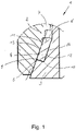
- FIG 2 shows the sealing ring 4 in section.
- the sealing ring 4 is conically designed to seal off the cooling medium and has a first end face 5 and a second end face 6 .
- the pressure of the cooling medium is applied to the first end face 5 and the second end face 6 faces the environment.
- a circumferential bead 7 is assigned to the second end face 6 , which points in the direction of the longitudinal axis 8 of the sealing ring 4 .
- the bead 7 has a semicircular shape and rests against the projection 13 with radial pretension.
- a circumferential groove 16 is made in the projection 13 to accommodate the sealing ring 4 .
- the first end face 5 is inclined at an angle of less than 90° relative to the longitudinal axis 8 .
- the first end face 5 has a first edge 9 and a second edge 10, the first edge 9 being subjected to the pressure of the cooling medium.
- the sealing ring 4 has an inner wall 11 and an outer wall 12 , the ring surface formed by the first end face 5 including an angle of 90° relative to the inner wall 11 .
- the annular surface formed by the first end face 5 encloses an angle of 90° relative to the outer wall 12 .
- the inner wall 11 is inclined at an angle of 15° relative to the longitudinal axis 8 .
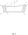
- FIG figure 3 shows a sealing ring 4 according to FIG figure 2 ,
- the first end face 5 in the present embodiment runs in a radial plane.
- the annular surface formed by the first end face 5 encloses an angle of 90° to the longitudinal axis 8 .
- figure 4 shows a further development of the figures 1 , 2 and 3 arrangement shown.
- a centering ring 17 is arranged in the annular space 15 .
- the centering ring 17 is made of polymeric material and is arranged on the free end of the projection 13 .
- the centering ring 17 is held on the projection 13 in a form-fitting manner.
- the centering ring 17 and the projection 13 have a congruently shaped sawtooth profile.
- the recess 14 is cylindrical in the section assigned to the centering ring 17 and the centering ring 17 is cylindrical on the outer peripheral side.
- the sealing ring 4 is corresponding figure 3 designed.
- the projection 13 and the recess 14 have a cylindrical and a conical section, so that the sealing ring 4 has turned. This lengthens the permeation path for the medium to be sealed, which improves the tightness of the arrangement 1.
- figure 5 shows a further embodiment of the arrangement 1 described above.
- two bores 18 are introduced into the first coupling element 2 and the second coupling element 3, with opposite bores 18 of the first coupling element 2 and the second coupling element 3 being aligned.
- a pin 19 is arranged in each pair of bores 18 , one pin 19 being fixed to the coupling element 2 and one pin to the second coupling element 3 .
Landscapes
- Engineering & Computer Science (AREA)
- General Engineering & Computer Science (AREA)
- Mechanical Engineering (AREA)
- Gasket Seals (AREA)
Abstract
Description
- Die Erfindung betrifft eine Anordnung zur Abdichtung einer Verbindung eines ersten Kupplungselementes mit einem zweiten Kupplungselement, wobei das erste Kupplungselement einen zumindest abschnittsweise konisch geformten Vorsprung aufweist und das zweite Kupplungselement mit einer zumindest abschnittsweise konisch geformten Ausnehmung versehen ist, wobei der Vorsprung in die Ausnehmung hineinragt, wobei sich zwischen Vorsprung und Ausnehmung ein Ringraum ergibt, in welchem ein Dichtring angeordnet ist, wobei der Dichtring zumindest abschnittsweise konisch ausgebildet ist und eine erste Stirnseite und eine zweite Stirnseite aufweist, wobei die erste Stirnseite in Richtung des Kühlmediums weist und die zweite Stirnseite in Richtung der Umgebung weist.
- Eine derartige Anordnung ist aus der
DE 10 2007 035 223 A1 bekannt. Dort ist beschrieben, dass Rohrleitungssysteme von Fahrzeugklimaanlagen für jede Verbindung ein lösbares Kupplungssystem aufweisen, welches aus zwei Kupplungselementen besteht. Zumeist ist ein erstes Kupplungselement ein mit einem Zapfen versehener Flansch, und ein zweites Kupplungselemente ist ein mit einer eingesenkten Ringnut versehener Flansch, die ineinander greifend verschraubt oder auf eine andere Weise verspannt werden. Die Dichtheit der Verbindung wird durch einen Dichtring gewährleistet, der zwischen den beiden Flanschen angeordnet ist. Bekannt ist beispielsweise ein Dichtelement in Form eines O-Ringes aus elastomerem Werkstoff. Ferner bekannt sind aus metallischen Scheiben oder Schneidringen ausgeformte Dichtungen. - Das vorbekannte Dichtelement ist zumindest teilweise konisch ausgebildet und in entsprechend geformte Aufnahmen der beiden Elemente eingelegt.
- Problematisch ist, dass das Kühlmedium in einer Klimaanlage unter einem hohen Druck steht. Dies gilt insbesondere, wenn das Kühlmedium R744, entsprechend Kohlenstoffdioxid CO2, ist. Beispielsweise weist CO2 bei 20°C einen Siededruck von 57 bar auf. Schon allein vor diesem Hintergrund sind an das Dichtelement hohe Anforderungen gestellt. Des Weiteren bereitet eine Wiedermontage, beispielsweise im Rahmen einer Reparatur häufig Probleme.
- Somit liegt der Erfindung die Aufgabe zugrunde, die vorbekannte Anordnung derart weiterzuentwickeln, dass die Gefahr einer Leckage reduziert ist.
- Diese Aufgabe wird mit den Merkmalen von Anspruch 1 gelöst. Auf vorteilhafte Ausgestaltungen nehmen die Unteransprüche Bezug.
- Zur Lösung der Aufgabe ist der zweiten Stirnseite des Dichtrings ein umlaufender Wulst zugeordnet, welcher aus dem Dichtring ausgebildet ist und welcher in Richtung der Längsachse des Dichtrings weist. Grundsätzlich weist der Dichtring die Form eines Hohlkegelstumpfes auf, dessen Querschnitt sich radial in Richtung der Umgebung stetig erweitert. In diesem Zusammenhang ist es aber auch denkbar, dass der Dichtring zusätzlich Querschnittsveränderungen wie Stufen oder zylindrische Abschnitte aufweisen kann.
- Die Formgebung des Dichtrings in Form eines Hohlkegelstumpfs bedeutet, dass die Stirnseite mit dem kleineren Querschnitt in das Innere der Anordnung weist, beispielsweise in Richtung der mit einem Kühlmedium druckbeaufschlagten Seite. Der Wulst wiederum ist der in Richtung der Umgebung zugewandten Stirnseite zugeordnet. Dabei weist der Wulst in Richtung der Längsachse des Dichtrings, also radial nach innen. Ein derartiger Dichtring ist einfach montierbar, da der Dichtring aufgrund seiner Querschnittsverjüngung einfach auf den Vorsprung des ersten Kupplungselementes aufgeschoben werden kann. Wird das zweite Kupplungselement in das erste Kupplungselement eingeschoben, legt sich der Wulst an die Innenwand der Ausnehmung des zweiten Kupplungselementes an und verbessert so die Dichtwirkung der Anordnung und reduziert insbesondere die Gefahr einer Leckage.
- Durch die Wulst ist der Dichtring darüber hinaus formschlüssig auf dem Kupplungselement gehalten. Dies ist insbesondere vorteilhaft, wenn die Kupplung im Rahmen einer Wartung oder Reparatur geöffnet und wieder geschlossen werden soll. Beim Lösen der Kupplung verbleibt der Dichtring aufgrund der formschlüssigen Verbindung auf dem ersten Kupplungselement. Beim Verschließen der Kupplung ist dabei der Dichtring lagerichtig auf dem ersten Kupplungselement fixiert. Dadurch ist es möglich, die Kupplung mehrfach zu öffnen und zu verschließen, wobei es jeweils nicht erforderlich ist, den Dichtring auszutauschen.
- In einer vorteilhaften Ausgestaltung ist der Wulst halbkreisförmig ausgebildet. Dadurch legt sich der Wulst bei Montage linienförmig an den Vorsprung des ersten Kupplungselementes an, wodurch sich bei Kompression des Wulstes während der Montage eine hohe Anpressung und damit eine hohe Dichtwirkung ergeben. Dabei ist die Halbkreisform mechanisch so stabil, dass der Wulst auch hohem Druck standhält, ohne dass sich dieser von dem Dichtring ablöst.
- Die Dichtwirkung der Wulst verbessert sich insbesondere dann, wenn der Wulst mit radialer Vorspannung an dem ersten Element anliegt.
- Vorzugsweise ist der Vorsprung zur Aufnahme der Wulst mit einer umlaufenden Nut versehen. Dadurch ist der Dichtring formschlüssig auf dem Vorsprung gehalten, was insbesondere während der Montage der Anordnung vorteilhaft ist, weil der Dichtring verliersicher gesichert ist. Des Weiteren verbessert die definierte Aufnahme der Wulst in der Nut die Dichtwirkung.
- In dem Ringraum kann ein Zentrierring angeordnet sein. Der Zentrierring stellt einen definierten Zwischenraum zwischen dem ersten Kupplungselement und dem zweiten Kupplungselement im Bereich von Vorsprung und Ausnehmung sicher. Dadurch erhöht sich die Betriebssicherheit der Anordnung und die Montage wird vereinfacht.
- Der Zentrierring ist dabei vorzugsweise an dem freien Ende des Vorsprungs angeordnet. Dadurch gelangen die Kupplungselemente während der Montage zunächst über den Zentrierring miteinander in Kontakt, was eine lagerichtige Montage der Anordnung erleichtert. Des Weiteren schützt der Zentrierring den Dichtring während der Montage.
- Vorzugsweise ist der Zentrierring formschlüssig auf dem Vorsprung gehalten. Dadurch ist der Zentrierring verliersicher auf dem Vorsprung gesichert, was insbesondere während der Montage vorteilhaft ist.
- Die Ausnehmung kann in dem dem Zentrierring zugeordneten Abschnitt zylindrisch ausgebildet sein und der Zentrierring kann außenumfangsseitig zylindrisch ausgebildet sein. Dadurch fluchten der Vorsprung und die Ausnehmung der Kupplungselemente während der Montage.
- In das erste Kupplungselement und das zweite Kupplungselement können Bohrungen eingebracht sein, wobei in zumindest einer Anordnung einander fluchtender Bohrungen ein Stift angeordnet sein kann. Vorzugsweise werden die Kupplungselemente mittels einer Schraubverbindung fest miteinander verbunden. Die Bohrungen und der in einem Paar Bohrungen angeordnete Stift verhindert, dass sich die Kupplungselemente zueinander verdrehen, was wiederum die Montage der Schraubverbindung erschweren würde.
- In das erste Kupplungselement und in das zweite Kupplungselement können jeweils zwei Bohrungen eingebracht sein, wobei einander gegenüberliegende Bohrungen von erstem Kupplungselement und zweitem Kupplungselement fluchten. Bei dieser Ausgestaltung kann die Anordnung mit zwei Stiften ausgerüstet sein. Hierbei ist vorteilhaft, dass mittels der Anordnung der Stifte eine Codierung der Kupplungselemente möglich ist. Dadurch können beispielsweise Kupplungselemente mit unterschiedlicher Ausrüstung montiert werden. Gemäß einer vorteilhaften Anwendung in Klimaanlagen von Kraftfahrzeugen gelangen unterschiedliche Dichtringe zum Einsatz, wobei ein Dichtring für die Hochdruckseite und ein zweiter Dichtring für die Niederdruckseite der Klimaanlage vorgesehen ist. Das erste Kupplungselement und das zweite Kupplungselement können dabei jeweils mit einem Stift ausgerüstet sein, welche so in den Elementen angeordnet sind, dass jeweils nur Kupplungselemente für die entsprechende Anwendung gefügt werden können. In diesem Sinne erfolgt durch die Anordnung der Bohrungen und Stifte eine Codierung. Im Zusammenspiel mit dem formschlüssig auf dem Vorsprung gehaltenen Dichtring ist eine besonders einfache Montage möglich, wobei es insbesondere möglich ist, die Kupplung blind zu montieren, so dass eine Montage auch in schwer erreichbaren und nicht einsehbaren Bereichen möglich ist.
- In einer vorteilhaften Ausgestaltung ist die erste Stirnseite unter einem Winkel von weniger als 90° relativ zur Längsachse des Dichtringes geneigt.
- In diesem Zusammenhang ist es insbesondere vorteilhaft, wenn die erste Stirnseite eine erste Kante und eine zweite Kante aufweist, wobei die erste Kante in den Ringraum weist. Bei dieser Ausgestaltung ist der Dichtring im Bereich der ersten Stirnseite so geneigt, dass lediglich die erste Kante mit dem im Inneren der Anordnung herrschenden Druck, beispielsweise mit dem Druck des Kühlmediums beaufschlagt ist, wohingegen die zweite Kante bereits auf der druckabgewandten Seite angeordnet ist. Hierbei ist insbesondere vorteilhaft, dass der Kraftfluss, welcher durch den Druck des Kühlmediums ausgeübt wird, in das Innere des Dichtrings weist. Vorzugsweise ist die Stirnseite derart geneigt, dass der Kraftfluss unter einem Winkel von 45° relativ zur Stirnseite in den Dichtring hineinweist. Bei dieser Ausgestaltung verursacht der durch das Kühlmedium ausgeübte Druck, dass sich der Dichtring von der druckbeaufschlagten ersten Kante weg in Richtung der zweiten Kante und gleichzeitig in Richtung der Wulst verdrängt wird.
- Dabei presst sich der Dichtring an das erste Kupplungselement an, was zu einer signifikanten Verbesserung der Dichtwirkung führt.
- Diese vorteilhafte Dichtwirkung wird dadurch nochmals verbessert, wenn der Dichtring eine Innenwand und eine Außenwand aufweist, wobei die durch die erste Stirnseite gebildete Ringfläche einen Winkel von 90° relativ zur Innenseite einschließt.
- Ebenso ist es vorteilhaft, wenn die durch die erste Stirnseite gebildete Ringfläche einen Winkel von 90° relativ zur Außenwand einschließt.
- Vorzugsweise ist der Dichtring aus elastomerem Werkstoff, insbesondere aus Ethylen-Propylen-Dien-Monomer (EPDM) ausgebildet. Dieser Werkstoff weist eine Resistenz gegen die meisten Kühlmedien, insbesondere auch gegenüber R744 auf.
- Die Konizität des Dichtrings ist vorzugsweise derart gewählt, dass die Innenwand relativ zur Längsachse des Dichtrings um einen Winkel von 10° bis 30°, vorzugsweise um 15° geneigt ist.
- In einer erfindungsgemäßen Verwendung kommt die Anordnung in einer Klimaanlage, insbesondere in einer mobilen Klimaanlage eines Fahrzeugs zum Einsatz.
- Einige Ausführungsbeispiele der erfindungsgemäßen Anordnung werden nachfolgend anhand der Figuren näher erläutert. Diese zeigen, jeweils schematisch:
- Fig. 1
- eine Anordnung einer Klimaanlage;
- Fig. 2
- den Dichtring im Schnitt;
- Fig. 3
- einen Dichtring mit radial verlaufender erster Stirnseite;
- Fig. 4
- eine Anordnung mit Zentrierring;
- Fig. 5
- eine Anordnung mit Zentrierstiften.
-
Figur 1 zeigt eine Anordnung 1 zur Abdichtung einer Verbindung eines ersten Kupplungselementes 2 mit einem zweiten Kupplungselement 3 einer Klimaanlage. - Die Klimaanlage ist als Fahrzeugklimaanlage ausgebildet und beinhaltet ein erstes Kupplungselement 2 und ein zweites Kupplungselement 3. Das erste Kupplungselement 2 und das zweite Kupplungselement 3 können dabei Rohrabschnitte der Klimaanlage oder Ein- und/oder Ausgänge von Klimaanlagenkomponenten wie beispielsweise Kompressor, Verdampfer, Expansionsventil oder Kondensator aufnehmen, wobei diese Komponenten vorzugsweise stoffschlüssig an die Kupplungselemente 2, 3 angebunden sind.
- Das erste Kupplungselement 2 weist einen abschnittsweise konisch geformten Vorsprung 13 auf und das zweite Kupplungselement 3 weist eine abschnittsweise konisch geformte Ausnehmung 14 auf. Dabei ragt der Vorsprung 13 in die Ausnehmung 14 hinein und zwischen Vorsprung 13 und Ausnehmung 14 ergibt sich ein Ringraum 15. In dem Ringraum 15 ein Dichtring 4 angeordnet 114, wobei der Dichtring 4 das in dem ersten Kupplungselement 2 und das in dem zweiten Kupplungselement 3 geführte Kühlmedium gegenüber der Umgebung abdichtet. Vorsprung 13 und Ausnehmung 14 bilden somit einen Dichtsitz zur Aufnahme des Dichtrings 4. Ein bevorzugtes Kühlmedium ist in diesem Zusammenhang R744. Der Dichtring 4 ist vorzugsweise aus Ethylen-Propylen-Dien-Monomer (EPDM) ausgebildet.
-
Figur 2 zeigt den Dichtring 4 im Schnitt. Der Dichtring 4 ist zur Abdichtung des Kühlmediums konisch ausgebildet und weist eine erste Stirnseite 5 und eine zweite Stirnseite 6 auf. Dabei ist die erste Stirnseite 5 mit dem Druck des Kühlmediums beaufschlagt und die zweite Stirnseite 6 der Umgebung zugewandt. - Der zweiten Stirnseite 6 ist ein umlaufender Wulst 7 zugeordnet, der in Richtung der Längsachse 8 des Dichtrings 4 weist. Der Wulst 7 ist halbkreisförmig ausgebildet und liegt mit radialer Vorspannung an dem Vorsprung 13 an. Zur Aufnahme des Dichtrings 4 ist in den Vorsprung 13 eine umlaufende Nut 16 eingebracht.
- Die erste Stirnseite 5 ist unter einem Winkel von weniger als 90° relativ zur Längsachse 8 geneigt. Dabei weist die erste Stirnseite 5 eine erste Kante 9 und eine zweite Kante 10 aufweist, wobei die erste Kante 9 mit dem Druck des Kühlmediums beaufschlagt ist.
- Der Dichtring 4 weist eine Innenwand 11 und eine Außenwand 12 auf, wobei die durch die erste Stirnseite 5 gebildete Ringfläche einen Winkel von 90° relativ zur Innenwand 11 einschließt. Die durch die erste Stirnseite 5 gebildete Ringfläche schließt einen Winkel von 90° relativ zur Außenwand 12 ein. Die Innenwand 11 ist relativ zur Längsachse 8 um einen Winkel von 15° geneigt.
-
Figur 3 zeigt einen Dichtring 4 gemäßFigur 2 , wobei die erste Stirnseite 5 bei der vorliegenden Ausgestaltung in einer Radialebene verläuft. Insofern schließt die durch die erste Stirnseite 5 gebildete Ringfläche zu der Längsachse 8 einen Winkel von 90° ein. -
Figur 4 zeigt eine Weiterbildung der in denFiguren 1 ,2 und3 gezeigten Anordnung. Bei dieser Ausgestaltung ist in dem Ringraum 15 ein Zentrierring 17 angeordnet. Der Zentrierring 17 ist aus polymerem Material ausgebildet und an dem freien Ende des Vorsprungs 13 angeordnet. Der Zentrierring 17 ist formschlüssig auf dem Vorsprung 13 gehalten. Hierzu weisen der Zentrierring 17 und der Vorsprung 13 ein kongruent geformtes Sägezahnprofil auf. Die Ausnehmung 14 ist in dem dem Zentrierring 17 zugeordneten Abschnitt zylindrisch ausgebildet ist und der Zentrierring 17 ist außenumfangsseitig zylindrisch ausgebildet. Der Dichtring 4 ist entsprechendFigur 3 ausgestaltet. Der Vorsprung 13 und die Ausnehmung 14 weisen einen zylindrischen und einen konischen Abschnitt auf, so dass der Dichtring 4 abgebogen ist. Dadurch verlängert sich der Permeationsweg für das abzudichtende Medium, was die Dichtheit der Anordnung 1 verbessert. -
Figur 5 zeigt eine weitere Ausgestaltung der zuvor beschriebenen Anordnung 1. Bei dieser Ausgestaltung sind in das erste Kupplungselement 2 und das zweite Kupplungselement 3 jeweils zwei Bohrungen 18 eingebracht, wobei einander gegenüberliegende Bohrungen 18 von erstem Kupplungselement 2 und zweitem Kupplungselement 3 fluchten. In jedem Paar von Bohrungen 18 ist ein Stift 19 angeordnet, wobei ein Stift 19 an dem Kupplungselement 2 und ein Stift an dem zweiten Kupplungselement 3 festgelegt ist.
Claims (12)
- Anordnung (1) zur Abdichtung einer Verbindung eines ersten Kupplungselementes (2) mit einem zweiten Kupplungselement (3), wobei das erste Kupplungselement (2) einen zumindest abschnittsweise konisch geformten Vorsprung (13) aufweist und das zweite Kupplungselement (3) mit einer zumindest abschnittsweise konisch geformten Ausnehmung (14) versehen ist, wobei der Vorsprung (13) in die Ausnehmung (14) hineinragt, wobei sich zwischen Vorsprung (13) und Ausnehmung (14) ein Ringraum (15) ergibt, in welchem ein Dichtring (4) angeordnet ist, wobei der Dichtring (4) zumindest abschnittsweise konisch ausgebildet ist und eine erste Stirnseite (5) und eine zweite Stirnseite (6) aufweist, wobei die erste Stirnseite (5) in Richtung des Ringraums (15) weist und die zweite Stirnseite (6) in Richtung der Umgebung weist, dadurch gekennzeichnet, dass der zweiten Stirnseite (6) ein umlaufender Wulst (7) zugeordnet ist, welcher aus dem Dichtring (4) ausgebildet ist und welcher in Richtung der Längsachse (8) des Dichtrings (4) weist.
- Anordnung nach Anspruch 1, dadurch gekennzeichnet, dass der Wulst (7) mit radialer Vorspannung an dem ersten Kupplungselement (2) anliegt.
- Anordnung nach Anspruch 2, dadurch gekennzeichnet, dass der Vorsprung (13) zur Aufnahme der Wulst (7) mit einer umlaufenden Nut (16) versehen ist.
- Anordnung nach einem der Ansprüche 1 bis 3, dadurch gekennzeichnet, dass in dem Ringraum (15) ein Zentrierring (17) angeordnet ist.
- Anordnung nach Anspruch 4, dadurch gekennzeichnet, dass der Zentrierring (17) an dem freien Ende des Vorsprungs (13) angeordnet ist.
- Anordnung nach Anspruch 4 oder 5, dadurch gekennzeichnet, dass der Zentrierring (17) formschlüssig auf dem Vorsprung (13) gehalten ist.
- Anordnung nach einem der Ansprüche 4 bis 6, dadurch gekennzeichnet, dass die Ausnehmung (14) in dem dem Zentrierring (17) zugeordneten Abschnitt zylindrisch ausgebildet ist und dass der Zentrierring (17) außenumfangsseitig zylindrisch ausgebildet ist.
- Anordnung nach einem der Ansprüche 1 bis 7, dadurch gekennzeichnet, dass in das erste Kupplungselement (2) und das zweite Kupplungselement (3) Bohrungen (18) eingebracht sind, wobei in zumindest einer Anordnung einander fluchtender Bohrungen (18) ein Stift (19) angeordnet ist.
- Anordnung nach Anspruch 8, dadurch gekennzeichnet, dass in das erste Kupplungselement (2) und das zweite Kupplungselement (3) jeweils zwei Bohrungen (18) eingebracht sind, wobei einander gegenüberliegende Bohrungen (18) von erstem Kupplungselement (2) und zweitem Kupplungselement (3) fluchten.
- Anordnung nach einem Ansprüche 1 bis 9, dadurch gekennzeichnet, dass die erste Stirnseite (5) eine erste Kante (9) und eine zweite Kante (10) aufweist, wobei die erste Kante (9) mit dem Druck des Kühlmediums beaufschlagt ist.
- Anordnung nach einem der Ansprüche 1 bis 7, dadurch gekennzeichnet, dass der Dichtring (4) aus elastomerem Werkstoff, vorzugsweise aus Ethylen-Propylen-Dien-Monomer (EPDM) ausgebildet ist.
- Verwendung der Anordnung (1) nach einem der vorherigen Ansprüche als Kupplung zweier Komponenten einer Klimaanlage.
Priority Applications (5)
| Application Number | Priority Date | Filing Date | Title |
|---|---|---|---|
| PL20202236.4T PL3985293T3 (pl) | 2020-10-16 | 2020-10-16 | Układ do uszczelniania połączenia |
| HRP20241130TT HRP20241130T1 (hr) | 2020-10-16 | 2020-10-16 | Sklop za brtvljenje spoja |
| EP20202236.4A EP3985293B1 (de) | 2020-10-16 | 2020-10-16 | Anordnung zur abdichtung einer verbindung |
| HUE20202236A HUE067995T2 (hu) | 2020-10-16 | 2020-10-16 | Elrendezés egy összeköttetés letömítésére |
| ES20202236T ES2986451T3 (es) | 2020-10-16 | 2020-10-16 | Disposición para sellar una conexión |
Applications Claiming Priority (1)
| Application Number | Priority Date | Filing Date | Title |
|---|---|---|---|
| EP20202236.4A EP3985293B1 (de) | 2020-10-16 | 2020-10-16 | Anordnung zur abdichtung einer verbindung |
Publications (2)
| Publication Number | Publication Date |
|---|---|
| EP3985293A1 true EP3985293A1 (de) | 2022-04-20 |
| EP3985293B1 EP3985293B1 (de) | 2024-06-05 |
Family
ID=73131623
Family Applications (1)
| Application Number | Title | Priority Date | Filing Date |
|---|---|---|---|
| EP20202236.4A Active EP3985293B1 (de) | 2020-10-16 | 2020-10-16 | Anordnung zur abdichtung einer verbindung |
Country Status (5)
| Country | Link |
|---|---|
| EP (1) | EP3985293B1 (de) |
| ES (1) | ES2986451T3 (de) |
| HR (1) | HRP20241130T1 (de) |
| HU (1) | HUE067995T2 (de) |
| PL (1) | PL3985293T3 (de) |
Citations (6)
| Publication number | Priority date | Publication date | Assignee | Title |
|---|---|---|---|---|
| DE3520949A1 (de) * | 1985-06-12 | 1986-12-18 | Hermann Mücher GmbH & Co KG, 5830 Schwelm | Gleitringdichtung fuer muffenrohrverbindungen |
| DE4231824A1 (de) * | 1992-09-23 | 1994-03-31 | Wagner Gmbh J | Leitungsverbindung |
| DE10261887A1 (de) * | 2002-12-20 | 2004-07-01 | Visteon Global Technologies, Inc., Dearborn | Rohrkupplung |
| EP1873437A2 (de) * | 2006-06-28 | 2008-01-02 | Hansa Automotive GmbH & Co. KG | Kältemittelleitung, insbesondere für mit CO2 betriebene Kraftfahrzeugklimaanlagen |
| DE102007035223A1 (de) | 2007-07-25 | 2009-01-29 | Behr Gmbh & Co. Kg | Dichtungsanordnung |
| EP3670990A1 (de) * | 2018-12-21 | 2020-06-24 | Hanon Systems | Metalldichtungsfassung mit tight-bend-technologie |
-
2020
- 2020-10-16 PL PL20202236.4T patent/PL3985293T3/pl unknown
- 2020-10-16 HU HUE20202236A patent/HUE067995T2/hu unknown
- 2020-10-16 HR HRP20241130TT patent/HRP20241130T1/hr unknown
- 2020-10-16 EP EP20202236.4A patent/EP3985293B1/de active Active
- 2020-10-16 ES ES20202236T patent/ES2986451T3/es active Active
Patent Citations (6)
| Publication number | Priority date | Publication date | Assignee | Title |
|---|---|---|---|---|
| DE3520949A1 (de) * | 1985-06-12 | 1986-12-18 | Hermann Mücher GmbH & Co KG, 5830 Schwelm | Gleitringdichtung fuer muffenrohrverbindungen |
| DE4231824A1 (de) * | 1992-09-23 | 1994-03-31 | Wagner Gmbh J | Leitungsverbindung |
| DE10261887A1 (de) * | 2002-12-20 | 2004-07-01 | Visteon Global Technologies, Inc., Dearborn | Rohrkupplung |
| EP1873437A2 (de) * | 2006-06-28 | 2008-01-02 | Hansa Automotive GmbH & Co. KG | Kältemittelleitung, insbesondere für mit CO2 betriebene Kraftfahrzeugklimaanlagen |
| DE102007035223A1 (de) | 2007-07-25 | 2009-01-29 | Behr Gmbh & Co. Kg | Dichtungsanordnung |
| EP3670990A1 (de) * | 2018-12-21 | 2020-06-24 | Hanon Systems | Metalldichtungsfassung mit tight-bend-technologie |
Also Published As
| Publication number | Publication date |
|---|---|
| PL3985293T3 (pl) | 2024-12-16 |
| ES2986451T3 (es) | 2024-11-11 |
| HUE067995T2 (hu) | 2024-12-28 |
| HRP20241130T1 (hr) | 2024-11-22 |
| EP3985293B1 (de) | 2024-06-05 |
Similar Documents
| Publication | Publication Date | Title |
|---|---|---|
| EP2027403B1 (de) | Dichtungsanordnung zur druckentlastung | |
| EP1445529B1 (de) | Verbindungsanordnung für Kältemittelleitungen | |
| EP1873437A2 (de) | Kältemittelleitung, insbesondere für mit CO2 betriebene Kraftfahrzeugklimaanlagen | |
| DE60129190T2 (de) | Ventil und Verfahren zur Ventilherstellung | |
| EP3203124A1 (de) | Elastomer-membranelement | |
| DE102005059208A1 (de) | Vakuumgehäuse | |
| WO2016046064A1 (de) | Vorrichtung zur dichtung eines ventils | |
| DE102023117369A1 (de) | Kugelventil einer Kältemittelventileinrichtung für eine Klimaanlage | |
| EP3246605A1 (de) | Membranventil | |
| EP2657583B1 (de) | Drei-fach-exzentrische Absperrarmatur | |
| EP3985293B1 (de) | Anordnung zur abdichtung einer verbindung | |
| DE102008029642A1 (de) | Tellerfederanordnung | |
| DE102005020259A1 (de) | Verbindungsanordnung für Kältemittelleitungen | |
| EP1548348B1 (de) | Dichtungsanordnung, insbesondere für einen Anschluss einer Leitung an einem Expansionsorgan | |
| EP3447329A1 (de) | Abdichtungsanordnung | |
| EP1841981B1 (de) | Scheibenbremse | |
| DE102020200859A1 (de) | Dichtkörper und Schraubverbindung mit einem solchen Dichtkörper | |
| DE10109515B4 (de) | Membran-Bremszylinder | |
| EP0492331B1 (de) | Absperr- oder Regelklappe | |
| DE102007045679A1 (de) | Dichtscheibe zur Abdichtung von Bauteilen | |
| DE102023118470A1 (de) | Membranventil | |
| DE102024131979A1 (de) | Seitenflanschverbindungsanordnung | |
| DE102024121875A1 (de) | Dichtungsanordnung für einen Ventilschieber und Schieberventil | |
| DE102022116238A1 (de) | Rückschlagventil für einen Kompressor eines Kraftfahrzeugs, Kompressor sowie betreffende Verwendung | |
| DE102007035223A1 (de) | Dichtungsanordnung |
Legal Events
| Date | Code | Title | Description |
|---|---|---|---|
| REG | Reference to a national code |
Ref country code: HR Ref legal event code: TUEP Ref document number: P20241130T Country of ref document: HR |
|
| PUAI | Public reference made under article 153(3) epc to a published international application that has entered the european phase |
Free format text: ORIGINAL CODE: 0009012 |
|
| STAA | Information on the status of an ep patent application or granted ep patent |
Free format text: STATUS: THE APPLICATION HAS BEEN PUBLISHED |
|
| AK | Designated contracting states |
Kind code of ref document: A1 Designated state(s): AL AT BE BG CH CY CZ DE DK EE ES FI FR GB GR HR HU IE IS IT LI LT LU LV MC MK MT NL NO PL PT RO RS SE SI SK SM TR |
|
| RIN1 | Information on inventor provided before grant (corrected) |
Inventor name: WEISS, RAINER Inventor name: WUNDERLE, RAPHAEL Inventor name: KUHNE, DAVID Inventor name: VOEHRINGER, MARC-CHRISTIAN Inventor name: MELCHER, ANDREAS |
|
| STAA | Information on the status of an ep patent application or granted ep patent |
Free format text: STATUS: REQUEST FOR EXAMINATION WAS MADE |
|
| 17P | Request for examination filed |
Effective date: 20221018 |
|
| RBV | Designated contracting states (corrected) |
Designated state(s): AL AT BE BG CH CY CZ DE DK EE ES FI FR GB GR HR HU IE IS IT LI LT LU LV MC MK MT NL NO PL PT RO RS SE SI SK SM TR |
|
| GRAP | Despatch of communication of intention to grant a patent |
Free format text: ORIGINAL CODE: EPIDOSNIGR1 |
|
| STAA | Information on the status of an ep patent application or granted ep patent |
Free format text: STATUS: GRANT OF PATENT IS INTENDED |
|
| INTG | Intention to grant announced |
Effective date: 20240124 |
|
| GRAS | Grant fee paid |
Free format text: ORIGINAL CODE: EPIDOSNIGR3 |
|
| GRAA | (expected) grant |
Free format text: ORIGINAL CODE: 0009210 |
|
| STAA | Information on the status of an ep patent application or granted ep patent |
Free format text: STATUS: THE PATENT HAS BEEN GRANTED |
|
| P01 | Opt-out of the competence of the unified patent court (upc) registered |
Effective date: 20240415 |
|
| AK | Designated contracting states |
Kind code of ref document: B1 Designated state(s): AL AT BE BG CH CY CZ DE DK EE ES FI FR GB GR HR HU IE IS IT LI LT LU LV MC MK MT NL NO PL PT RO RS SE SI SK SM TR |
|
| REG | Reference to a national code |
Ref country code: CH Ref legal event code: EP |
|
| REG | Reference to a national code |
Ref country code: DE Ref legal event code: R096 Ref document number: 502020008188 Country of ref document: DE |
|
| REG | Reference to a national code |
Ref country code: IE Ref legal event code: FG4D Free format text: LANGUAGE OF EP DOCUMENT: GERMAN |
|
| REG | Reference to a national code |
Ref country code: LT Ref legal event code: MG9D |
|
| PG25 | Lapsed in a contracting state [announced via postgrant information from national office to epo] |
Ref country code: BG Free format text: LAPSE BECAUSE OF FAILURE TO SUBMIT A TRANSLATION OF THE DESCRIPTION OR TO PAY THE FEE WITHIN THE PRESCRIBED TIME-LIMIT Effective date: 20240605 |
|
| REG | Reference to a national code |
Ref country code: NL Ref legal event code: MP Effective date: 20240605 Ref country code: SK Ref legal event code: T3 Ref document number: E 44756 Country of ref document: SK |
|
| PG25 | Lapsed in a contracting state [announced via postgrant information from national office to epo] |
Ref country code: FI Free format text: LAPSE BECAUSE OF FAILURE TO SUBMIT A TRANSLATION OF THE DESCRIPTION OR TO PAY THE FEE WITHIN THE PRESCRIBED TIME-LIMIT Effective date: 20240605 |
|
| PG25 | Lapsed in a contracting state [announced via postgrant information from national office to epo] |
Ref country code: GR Free format text: LAPSE BECAUSE OF FAILURE TO SUBMIT A TRANSLATION OF THE DESCRIPTION OR TO PAY THE FEE WITHIN THE PRESCRIBED TIME-LIMIT Effective date: 20240906 |
|
| PG25 | Lapsed in a contracting state [announced via postgrant information from national office to epo] |
Ref country code: LV Free format text: LAPSE BECAUSE OF FAILURE TO SUBMIT A TRANSLATION OF THE DESCRIPTION OR TO PAY THE FEE WITHIN THE PRESCRIBED TIME-LIMIT Effective date: 20240605 |
|
| PG25 | Lapsed in a contracting state [announced via postgrant information from national office to epo] |
Ref country code: NO Free format text: LAPSE BECAUSE OF FAILURE TO SUBMIT A TRANSLATION OF THE DESCRIPTION OR TO PAY THE FEE WITHIN THE PRESCRIBED TIME-LIMIT Effective date: 20240905 Ref country code: LV Free format text: LAPSE BECAUSE OF FAILURE TO SUBMIT A TRANSLATION OF THE DESCRIPTION OR TO PAY THE FEE WITHIN THE PRESCRIBED TIME-LIMIT Effective date: 20240605 Ref country code: GR Free format text: LAPSE BECAUSE OF FAILURE TO SUBMIT A TRANSLATION OF THE DESCRIPTION OR TO PAY THE FEE WITHIN THE PRESCRIBED TIME-LIMIT Effective date: 20240906 Ref country code: FI Free format text: LAPSE BECAUSE OF FAILURE TO SUBMIT A TRANSLATION OF THE DESCRIPTION OR TO PAY THE FEE WITHIN THE PRESCRIBED TIME-LIMIT Effective date: 20240605 Ref country code: BG Free format text: LAPSE BECAUSE OF FAILURE TO SUBMIT A TRANSLATION OF THE DESCRIPTION OR TO PAY THE FEE WITHIN THE PRESCRIBED TIME-LIMIT Effective date: 20240605 Ref country code: RS Free format text: LAPSE BECAUSE OF FAILURE TO SUBMIT A TRANSLATION OF THE DESCRIPTION OR TO PAY THE FEE WITHIN THE PRESCRIBED TIME-LIMIT Effective date: 20240905 |
|
| REG | Reference to a national code |
Ref country code: HR Ref legal event code: ODRP Ref document number: P20241130T Country of ref document: HR Payment date: 20240924 Year of fee payment: 5 |
|
| REG | Reference to a national code |
Ref country code: ES Ref legal event code: FG2A Ref document number: 2986451 Country of ref document: ES Kind code of ref document: T3 Effective date: 20241111 |
|
| PG25 | Lapsed in a contracting state [announced via postgrant information from national office to epo] |
Ref country code: NL Free format text: LAPSE BECAUSE OF FAILURE TO SUBMIT A TRANSLATION OF THE DESCRIPTION OR TO PAY THE FEE WITHIN THE PRESCRIBED TIME-LIMIT Effective date: 20240605 |
|
| REG | Reference to a national code |
Ref country code: HR Ref legal event code: T1PR Ref document number: P20241130 Country of ref document: HR |
|
| PG25 | Lapsed in a contracting state [announced via postgrant information from national office to epo] |
Ref country code: NL Free format text: LAPSE BECAUSE OF FAILURE TO SUBMIT A TRANSLATION OF THE DESCRIPTION OR TO PAY THE FEE WITHIN THE PRESCRIBED TIME-LIMIT Effective date: 20240605 |
|
| PG25 | Lapsed in a contracting state [announced via postgrant information from national office to epo] |
Ref country code: PT Free format text: LAPSE BECAUSE OF FAILURE TO SUBMIT A TRANSLATION OF THE DESCRIPTION OR TO PAY THE FEE WITHIN THE PRESCRIBED TIME-LIMIT Effective date: 20241007 |
|
| REG | Reference to a national code |
Ref country code: HU Ref legal event code: AG4A Ref document number: E067995 Country of ref document: HU |
|
| PG25 | Lapsed in a contracting state [announced via postgrant information from national office to epo] |
Ref country code: PT Free format text: LAPSE BECAUSE OF FAILURE TO SUBMIT A TRANSLATION OF THE DESCRIPTION OR TO PAY THE FEE WITHIN THE PRESCRIBED TIME-LIMIT Effective date: 20241007 |
|
| PG25 | Lapsed in a contracting state [announced via postgrant information from national office to epo] |
Ref country code: EE Free format text: LAPSE BECAUSE OF FAILURE TO SUBMIT A TRANSLATION OF THE DESCRIPTION OR TO PAY THE FEE WITHIN THE PRESCRIBED TIME-LIMIT Effective date: 20240605 |
|
| PG25 | Lapsed in a contracting state [announced via postgrant information from national office to epo] |
Ref country code: IS Free format text: LAPSE BECAUSE OF FAILURE TO SUBMIT A TRANSLATION OF THE DESCRIPTION OR TO PAY THE FEE WITHIN THE PRESCRIBED TIME-LIMIT Effective date: 20241005 |
|
| PG25 | Lapsed in a contracting state [announced via postgrant information from national office to epo] |
Ref country code: SM Free format text: LAPSE BECAUSE OF FAILURE TO SUBMIT A TRANSLATION OF THE DESCRIPTION OR TO PAY THE FEE WITHIN THE PRESCRIBED TIME-LIMIT Effective date: 20240605 |
|
| PG25 | Lapsed in a contracting state [announced via postgrant information from national office to epo] |
Ref country code: SM Free format text: LAPSE BECAUSE OF FAILURE TO SUBMIT A TRANSLATION OF THE DESCRIPTION OR TO PAY THE FEE WITHIN THE PRESCRIBED TIME-LIMIT Effective date: 20240605 Ref country code: IS Free format text: LAPSE BECAUSE OF FAILURE TO SUBMIT A TRANSLATION OF THE DESCRIPTION OR TO PAY THE FEE WITHIN THE PRESCRIBED TIME-LIMIT Effective date: 20241005 Ref country code: EE Free format text: LAPSE BECAUSE OF FAILURE TO SUBMIT A TRANSLATION OF THE DESCRIPTION OR TO PAY THE FEE WITHIN THE PRESCRIBED TIME-LIMIT Effective date: 20240605 |
|
| PG25 | Lapsed in a contracting state [announced via postgrant information from national office to epo] |
Ref country code: IT Free format text: LAPSE BECAUSE OF FAILURE TO SUBMIT A TRANSLATION OF THE DESCRIPTION OR TO PAY THE FEE WITHIN THE PRESCRIBED TIME-LIMIT Effective date: 20240605 |
|
| REG | Reference to a national code |
Ref country code: DE Ref legal event code: R097 Ref document number: 502020008188 Country of ref document: DE |
|
| PLBE | No opposition filed within time limit |
Free format text: ORIGINAL CODE: 0009261 |
|
| STAA | Information on the status of an ep patent application or granted ep patent |
Free format text: STATUS: NO OPPOSITION FILED WITHIN TIME LIMIT |
|
| PG25 | Lapsed in a contracting state [announced via postgrant information from national office to epo] |
Ref country code: DK Free format text: LAPSE BECAUSE OF FAILURE TO SUBMIT A TRANSLATION OF THE DESCRIPTION OR TO PAY THE FEE WITHIN THE PRESCRIBED TIME-LIMIT Effective date: 20240605 |
|
| 26N | No opposition filed |
Effective date: 20250306 |
|
| PG25 | Lapsed in a contracting state [announced via postgrant information from national office to epo] |
Ref country code: MC Free format text: LAPSE BECAUSE OF FAILURE TO SUBMIT A TRANSLATION OF THE DESCRIPTION OR TO PAY THE FEE WITHIN THE PRESCRIBED TIME-LIMIT Effective date: 20240605 |
|
| PG25 | Lapsed in a contracting state [announced via postgrant information from national office to epo] |
Ref country code: LU Free format text: LAPSE BECAUSE OF NON-PAYMENT OF DUE FEES Effective date: 20241016 |
|
| PG25 | Lapsed in a contracting state [announced via postgrant information from national office to epo] |
Ref country code: SE Free format text: LAPSE BECAUSE OF FAILURE TO SUBMIT A TRANSLATION OF THE DESCRIPTION OR TO PAY THE FEE WITHIN THE PRESCRIBED TIME-LIMIT Effective date: 20240605 |
|
| PGFP | Annual fee paid to national office [announced via postgrant information from national office to epo] |
Ref country code: HR Payment date: 20250923 Year of fee payment: 6 |
|
| PG25 | Lapsed in a contracting state [announced via postgrant information from national office to epo] |
Ref country code: IE Free format text: LAPSE BECAUSE OF NON-PAYMENT OF DUE FEES Effective date: 20241016 |
|
| PGFP | Annual fee paid to national office [announced via postgrant information from national office to epo] |
Ref country code: CZ Payment date: 20250929 Year of fee payment: 6 |
|
| REG | Reference to a national code |
Ref country code: HR Ref legal event code: ODRP Ref document number: P20241130 Country of ref document: HR Payment date: 20250923 Year of fee payment: 6 |
|
| PGFP | Annual fee paid to national office [announced via postgrant information from national office to epo] |
Ref country code: SK Payment date: 20250930 Year of fee payment: 6 |
|
| REG | Reference to a national code |
Ref country code: CH Ref legal event code: U11 Free format text: ST27 STATUS EVENT CODE: U-0-0-U10-U11 (AS PROVIDED BY THE NATIONAL OFFICE) Effective date: 20251101 |
|
| PGFP | Annual fee paid to national office [announced via postgrant information from national office to epo] |
Ref country code: HU Payment date: 20251009 Year of fee payment: 6 |
|
| PGFP | Annual fee paid to national office [announced via postgrant information from national office to epo] |
Ref country code: DE Payment date: 20251028 Year of fee payment: 6 |
|
| PGFP | Annual fee paid to national office [announced via postgrant information from national office to epo] |
Ref country code: GB Payment date: 20251023 Year of fee payment: 6 |
|
| PGFP | Annual fee paid to national office [announced via postgrant information from national office to epo] |
Ref country code: AT Payment date: 20251020 Year of fee payment: 6 |
|
| PGFP | Annual fee paid to national office [announced via postgrant information from national office to epo] |
Ref country code: FR Payment date: 20251027 Year of fee payment: 6 |
|
| PGFP | Annual fee paid to national office [announced via postgrant information from national office to epo] |
Ref country code: BE Payment date: 20251024 Year of fee payment: 6 |
|
| PGFP | Annual fee paid to national office [announced via postgrant information from national office to epo] |
Ref country code: CH Payment date: 20251101 Year of fee payment: 6 |
|
| PGFP | Annual fee paid to national office [announced via postgrant information from national office to epo] |
Ref country code: PL Payment date: 20250922 Year of fee payment: 6 |
|
| PGFP | Annual fee paid to national office [announced via postgrant information from national office to epo] |
Ref country code: RO Payment date: 20251003 Year of fee payment: 6 |
|
| PG25 | Lapsed in a contracting state [announced via postgrant information from national office to epo] |
Ref country code: CY Free format text: LAPSE BECAUSE OF FAILURE TO SUBMIT A TRANSLATION OF THE DESCRIPTION OR TO PAY THE FEE WITHIN THE PRESCRIBED TIME-LIMIT; INVALID AB INITIO Effective date: 20201016 |
|
| PGFP | Annual fee paid to national office [announced via postgrant information from national office to epo] |
Ref country code: ES Payment date: 20251118 Year of fee payment: 6 |