EP3985196B1 - Regenrinne - Google Patents
Regenrinne Download PDFInfo
- Publication number
- EP3985196B1 EP3985196B1 EP21203045.6A EP21203045A EP3985196B1 EP 3985196 B1 EP3985196 B1 EP 3985196B1 EP 21203045 A EP21203045 A EP 21203045A EP 3985196 B1 EP3985196 B1 EP 3985196B1
- Authority
- EP
- European Patent Office
- Prior art keywords
- gutter
- brace
- coupling
- lever
- flange
- Prior art date
- Legal status (The legal status is an assumption and is not a legal conclusion. Google has not performed a legal analysis and makes no representation as to the accuracy of the status listed.)
- Active
Links
Images


Classifications
-
- E—FIXED CONSTRUCTIONS
- E04—BUILDING
- E04D—ROOF COVERINGS; SKY-LIGHTS; GUTTERS; ROOF-WORKING TOOLS
- E04D13/00—Special arrangements or devices in connection with roof coverings; Protection against birds; Roof drainage ; Sky-lights
- E04D13/04—Roof drainage; Drainage fittings in flat roofs, balconies or the like
- E04D13/064—Gutters
- E04D13/072—Hanging means
- E04D13/0727—Hanging means situated mainly at the rear side of the gutter
-
- E—FIXED CONSTRUCTIONS
- E04—BUILDING
- E04D—ROOF COVERINGS; SKY-LIGHTS; GUTTERS; ROOF-WORKING TOOLS
- E04D13/00—Special arrangements or devices in connection with roof coverings; Protection against birds; Roof drainage ; Sky-lights
- E04D13/04—Roof drainage; Drainage fittings in flat roofs, balconies or the like
- E04D13/064—Gutters
- E04D13/0641—Gutter ends
-
- E—FIXED CONSTRUCTIONS
- E04—BUILDING
- E04D—ROOF COVERINGS; SKY-LIGHTS; GUTTERS; ROOF-WORKING TOOLS
- E04D13/00—Special arrangements or devices in connection with roof coverings; Protection against birds; Roof drainage ; Sky-lights
- E04D13/04—Roof drainage; Drainage fittings in flat roofs, balconies or the like
- E04D13/064—Gutters
- E04D13/0643—Gutter corners
-
- E—FIXED CONSTRUCTIONS
- E04—BUILDING
- E04D—ROOF COVERINGS; SKY-LIGHTS; GUTTERS; ROOF-WORKING TOOLS
- E04D13/00—Special arrangements or devices in connection with roof coverings; Protection against birds; Roof drainage ; Sky-lights
- E04D13/04—Roof drainage; Drainage fittings in flat roofs, balconies or the like
- E04D13/064—Gutters
- E04D13/068—Means for fastening gutter parts together
- E04D13/0685—Means for fastening gutter parts together in combination with hanging means
-
- E—FIXED CONSTRUCTIONS
- E04—BUILDING
- E04D—ROOF COVERINGS; SKY-LIGHTS; GUTTERS; ROOF-WORKING TOOLS
- E04D13/00—Special arrangements or devices in connection with roof coverings; Protection against birds; Roof drainage ; Sky-lights
- E04D13/04—Roof drainage; Drainage fittings in flat roofs, balconies or the like
- E04D13/064—Gutters
- E04D13/072—Hanging means
- E04D13/0725—Hanging means situated above or inside the gutter
Definitions
- Gutters have been known almost as long as people make buildings and houses. Known gutters mostly connect to roofs. These gutters were made from wood, ceramic, and even from tin (pewter) or copper. In the last 50 years, gutters made from polymer material have been introduced. Most of these gutters were single walled, requiring much coupling support. Examples of these gutters are in EP869230 .
- NL194090C (pubished as NL9202157 ) introduced one of the first self-supporting gutters from synthetic material or polymer, in that case from PVC (polyvinylchloride).
- PVC polyvinylchloride
- the gutter element is hollow-walled and is provided with double walls which are connected to one another by longitudinal partitions, which
- EP097 1083 in its abstract states: "Device for roof gutter parts (2a,2b) to be connected to each other, which roof gutter parts have a front wall (6a,6b), a bottom wall (3a,3b) and a rear wall (4a,4b), which merge into each other via discontinuities - such as buckles-, comprising two coupling members (8,9), which each substantially follow the shape of the roof gutter parts in cross-section, as well as means for biassing the coupling members to each other to hold the adjacent ends of the roof gutter parts in between them, the upper coupling member being provided with at least one receiving space, such as a channel, for attaching a sealing profile therein which profile is destined to lie on the ends of the roof gutter parts, the sealing profile being formed by injection moulding, the biassing means being adapted to exert a pressure force on the sealing profile to press it against the inner surface of the gutter wall.”
- WO2004/011738 in its abstract states: "The invention is directed to a gutter system for channeling rainwater from a building.
- the gutter system includes gutter sections that are interconnected with joint members having gaskets incorporated thereon.
- Each gutter section has a substantially hollow space defined between inner and outer walls that are spanned by a plurality of ribs.”
- the inside joint is a plate-like material having an elastic portion that has a groove portion to support and tries to return to the flat plate state, and both edges are folded back to form a locking portion, and the locking portion is formed in the groove portion of the eaves gutter main body.
- JPS638317U seems to relate to coupling of gutter ends using complementary end parts that abut ( figure 1-8 ).
- a (machine) translation of the description states: "The connecting device for an eaves gutter is characterized in that a sealing material filling space for holding a sealing material is formed between both connecting members when the projecting part of the other connecting member is fitted into a recessed part provided in one connecting member.”
- JP2003 147919 according to its abstract is "To provide a gutter hook capable of smoothly performing fitting work simply without using a spring material for stopping, and surely preventing a gutter from falling out.
- SOLUTION In this gutter hook, one end part and the other end part of a body part 2 provided with fitting parts 1 for fitting in a designated position of a building are provided with a locking part 5 for locking the lug part 4 of a gutter 3. At least one locking part 5 supports and stops one of the lug parts 4 to inhibit the gutter from being engaged and disengaged.
- An insert space 8 for inserting one lug part 4 projected to the inside of the gutter 3 is provided between a fitting support part 6 and an opposite part 7, and the fitting support part 6 is provided with an engagement and disengagement inhibiter part 9 projected into the insert space 8.
- the engagement and disengagement inhibiter part 9 is supported on the fitting support part 6, and provided to turn upward, whereby in inserting the lug part 4 from the lower side to the upper side through the insert space 8, the engagement and disengagement inhibiter part 9 is turned upward and retreated, and when the lug part 4 goes over the engagement and disengagement inhibiter part 9, the engagement and disengagement inhibiter part 9 is turned to return downward, and supported by the fitting support part 6, and the lug part 4 is supported and locked on the engagement and disengagement inhibiter part 9 on the fitting support part 6.”
- JP2003221900 in its abstract states: "PROBLEM TO BE SOLVED: To provide a vertical turning lock type rain gutter supporting member which allows a vertical turning lock lever to be operated in either of forward and backward directions, can eliminate a load imposed locally on a lower end of a shaft, can enhance strength of a rain gutter supporting tool body, and can be operated for vertical turning from either of positions above and below a mounting rod.
- This vertical turning lock type rain gutter supporting member A is equipped with the mounting rod 1 in which a stopper piece 13 is formed, the gutter supporting member body 2 which is slidable forward and backward, the vertical turning lock lever 3 which is formed with a locking part 33 capable of being engaged with/disengaged from the stopper piece 13 of the mounting rod 1, and a coupling shaft 4 which supports the body 2 and is passed through a shaft hole 32 of the lever 3 and a guide hole 11 of the body 2 from a lateral direction. Escape spaces 3a and 3b, from which the stopper piece 13 can be disengaged, are formed at front and back ends of a closed top surface of the lock lever 3."
- a disadvantage of prior art is that most gutters from synthetic material lack functionality and can not be applied on many known buildings. Most gutters are too heavy, deform, are complicated to install, especially when working in high places. Furthermore, they are often aesthetically not pleasing as they are all similar.
- the gutter is self supporting, even under high loads like snow. Mounting is improved, aesthetics is improved. Thermal expansion can be handled.
- a mounting rail allows a sliding degree of motion of the gutter with respect to the mounting rail and thus a building in the longitudinal direction of the gutter.
- the gutter is produced in lengths of up to 8 meters. Such a length can easily be transported to a site of use. Usually, a gutter of this type will be produced in an extrusion process. This type of process is well known and results in a double walled, self supporting gutter. Attachment of such a gutter can be simplified and swifter. Furthermore, the attachment allows gutter ends to slide when mounted. This makes the mounting able to handle dynamic situations, like working of building parts, temperature changes, and the like.
- the production allows for incorporating additional features like additional rails, or other coupling means that allows attachment or coupling of further parts like lists, aesthetic profiles, reinforcement parts, braces.
- the current gutter is also referred to as synthetic material gutter or plastic gutter.
- the gutter can in particular be made of synthetic material that can be extruded.
- the synthetic gutter can be made of polyvinylchloride (PVC).
- the gutter is produced by additive manufacturing. This is also referred to as "3D printing". In this method, each time a new layer is added, thus producing a length of gutter.
- the gutter assembly comprises an attachment rail, wherein the attachment rail comprises a mounting recess in said outer wall part, and a mounting rail comprising a mounting ledge fitting said attachment rail.
- the mounting recess comprised an undercut groove
- said mounting rail comprises a U-shaped edge fitting, in particular snap-fitting, into said undercut groove of said mounting recess.
- Said mounting ledge is also called “mounting strip rail/flange” in the following description.
- the inner gutter wall comprises a gutter bottom, a building side inner wall extending from said gutter bottom and an opposite outer side inner wall extending from said gutter bottom, and said gutter comprising an building side gutter edge and an opposite outer gutter edge.
- the gutter assembly further comprises a gutter coupling assembly for coupling two gutters with their ends for providing a continuous gutter.
- the gutter coupling assembly comprises:
- said first gutter coupling part comprises a gutter attaching end for attaching to said end of one of said two gutters, and a first coupling flange.
- said second gutter coupling part comprises a gutter attachment end for attaching to said end of the other of said two gutters, and gutter coupling sealing flange shaped for in operation allowing said first coupling flange to slide over said gutter coupling sealing flange.
- the gutter attachment end of said first and said second gutter coupling part each comprise a coupling plate substantially matching a cross section of said gutter, for attaching, in particular fixing, to a gutter end, for instance fixing using adhesive.
- the gutter attachment end further comprises a gutter coupling attachment flange comprising an outer surface matching an inner surface of the gutter for allowing coupling, in an embodiment attaching, the gutter coupling attachment flange and said inner surface of the gutter.
- the coupling flange has a gutter side
- said second sealing flange has a sealing surface which sealing surface and gutter side are sealingly flush with an inner surface of the gutter attachment flange.
- the gutter is produced in a process selected from extrusion and additive manufacturing, and which is substantially from a polymer material, preferably from PVC.
- the gutter assembly further comprises a water sensor for providing a warning signal in case of gutter clogging.
- the water sensor comprises a sensing element for detecting a water level in said gutter, in an embodiment extending into said gutter up to a predefined height above a gutter lower inner wall for detecting water above a predefined water height level (wh) in said gutter.
- the water sensor further comprises an attachment part for attaching, in particular snapping, said water sensor onto said gutter.
- the water sensor comprises a power supply, in particular a photovoltaic element (101), for providing operational electrical power to said water sensor.
- the water sensor comprises a wireless transmitter for transmitting a signal when a water level is detected.
- a water sensor for determining a water level in a gutter said water sensor not being an embodiment of the present invention, said water sensor comprising:
- the computer program when receiving a first signal from the water detector, and when receiving a further signal from said water detector at a predetermined time from said first signal, issues a gutter clogged signal via said wireless transmitter.
- said gutter clogged signal is issued after receiving several signals from said water detector at predetermined time intervals.
- a coupling assembly for coupling ends of gutter together allowing water to flow between the ends of gutter, said coupling assembly not being an embodiment of the present invention, wherein said gutter attachment end of said first and said second gutter coupling part each comprise a coupling plate substantially matching a cross section of said gutter, for attaching, in particular fixing, to a gutter end, for instance fixing using adhesive.
- upstream and downstream relate to an arrangement of items or features relative to the flow of water from a source position to a drain position. For instance, in the gutter water flows from an upstream end to a downstream end.
- a gutter assembly which comprises a gutter produced in a process selected from extrusion and additive manufacturing or a combination thereoff, and which is substantially from a polymer material, preferably from PVC, said gutter comprising a building side and an opposite outer side, which gutter is double walled, and comprises an inner wall and an outer wall and ribs connecting said inner wall and outer wall, providing a functionally self supporting gutter.
- substantially herein, such as in “substantially rectangular” or in “substantially consists”, will be understood by the person skilled in the art.
- the term “substantially” may also include embodiments with “entirely”, “completely”, “all”, etc. Hence, in embodiments the adjective substantially may also be removed.
- the term “substantially” may also relate to 90% or higher, such as 95% or higher, especially 99% or higher, even more especially 99.5% or higher, including 100%.
- the term “comprise” includes also embodiments wherein the term “comprises” means “consists of”.
- the term “functionally” is intended to cover variations in the feature to which it refers, and which variations are such that in the functional use of the feature, possibly in combination with other features it relates to in the invention, that combination of features is able to operate or function. For instance, if an antenna is functionally coupled or functionally connected to a communication device, received electromagnetic signals that are receives by the antenna can be used by the communication device.
- the word “functionally” as for instance used in “functionally parallel” is used to cover exactly parallel, but also the embodiments that are covered by the word “substantially” explained above.
- “functionally parallel” relates to embodiments that in operation function as if the parts are for instance parallel. This covers embodiments for which it is clear to a skilled person that it operates within its intended field of use as if it were parallel.
- FIG. 1 schematically depicts a perspective view of a gutter 1, and figure 2 shows a side view.
- the gutter 1 is an extruded gutter or is manufactured using additive manufacturing, also referred to as 3D printing.
- the gutter 1 is double walled, comprising an inner wall 2, and outer wall 3, and reinforcing ribs 4 connecting the inner wall 2 and outer wall 3.
- the inner wall 2 and outer wall 3 connect at opposite gutter edges 9.
- the gutter 1 is generally channel shaped and has a gutter bottom 8.
- the gutter 1 has a side that is in used mounted against or directed towards a building. This side is indicated with B, Building side. The opposite side is indicated O, outer side.
- the gutter 1 is elongated or extends in longitudinal direction. Connected to and extending from the gutter bottom 8 are a building side inner wall 11 and an outer side inner wall 10.
- the building side inner wall 11, outer side inner wall 10, and gutter bottom 8 together define the channel shape for receiving water and guiding the received water away to a drain pipe.
- the gutter 1 comprises several grooves, rails, recesses and flanges extending in longitudinal direction. These grooves, rails, flanges and recesses provide attachment, mounting and/or coupling parts for various other parts.
- the gutter 1 has a building side outer wall 5.
- This building side outer all 5 here comprises two parallel mounting recesses 6 providing gutter attachment rails. that in this embodiment provide a one-sided undercut groove 12.
- the undercutting 12 provides the mounting recess 6 with a gutter mounting flange 13.
- the gutter mounting flange 13 extends in gutter bottom 8 direction.
- the gutter 1 comprises in this embodiment two mounting strips 7, one for each mounting recess 6.
- Mounting strip 7 on one side has a U-shape side which proves the mounting strip 7 with a mounting strip/rail flange 14.
- the dimensions of the mounting recess 6, undercutting 12 and gutter mounting flange 13 on one side and the U-shape side and mounting strip flange 14 are mutually designed and dimensioned to provide a snap fit when mounting strip flange 14 is introduced into the undercutting 12 as depicted in figure 2 .
- the mounting strip flange 14 extends away from the strip body.
- mounting rail flange 14 and mounting rail body 15 are not parallel.
- the angle is between 5 and 20 degrees. In particular between 10 and 20 degrees.
- the end of gutter mounting flange 13 is thickened in te direction of the building side inner wall 11. Furthermore, in this embodiment, the flaring out or extending of the mounting strip flange 14 starts about one third of its width. When the gutter mounting flange 13 enters the U-shaped side of the mounting strip, it pushes the flange a little away from the mounting strip 7 and against a wall of the mounting recess 6. This provides fixation.
- the mounting strip 7 runs along substantially the full length of the gutter 1. In this way, a secure and aligned mounting is ensured. It is also possible to use shorter ends of mounting strip 7, but in such instances, mutual alignment of these ends of mounting strip 7 is required.
- the gutter 1 has two mounting recesses 6. This allows either more firm fixation, or can provide two different mounting options.
- a mounting rail 7 can be attached or fixed to a building. If a screw head extends, it will fall in the additional recess above the mounting recess 6.
- the mounting rail 7 can be made from synthetic material. It may also be made from aluminium.
- the gutter 1 further comprises an inner flange 23 extending inward and comprising an end bending towards the gutter bottom 8. This in fact provides an undercut rail.
- Gutter 1 or better the gutter edge 9 at the outer side of the gutter 1, is further provided with an outer side gutter edge groove 17.
- the ribs 4, 4', 4", 4′′′ have a thickness of between 0.2-2 mm.
- the thickness of the ribs is 0.5-1.5 mm.
- the ribs have a thickness of 0.7-1.1 mm. It was found that this provides an optimal trade off between raw material used and strength. Furthermore, the thickness allows gluing ends and other parts.
- a distance between the inner wall and outer wall is between 1 cm and 5 cm. In particular the distance between the bottom inner wall and outer wall is between 1.5-5 cm.
- the recesses, profiles and flanges are functional for attaching parts, and provide additional strength and reinforcement.
- the ribs 4 that extend longitudinally have been carefully designed orientation that provides optimal strength while at the same time reducing material and weight.
- ribs 4 are provided that are slanted.
- these slanted bottom ribs 4' connect the gutter bottom wall 8 and the outer gutter wall 3.
- these slanted bottom ribs 4' are at an angle of between 35 and 55 degrees, in particular between 38 and 52 degrees.
- the slanted ribs 4' are slanted from the gutter bottom wall 8 away from the building side B.
- the gutter bottom wall 8 has uprising parts 8' at the building side B and the outer side O. These uprising parts 8' have ribs 4′′′ that are in plane with the uprising parts 8' and connect to the outer gutter wall 3 (one of the slanted ribs 4' is also a rib 4′′′ of one of the uprising parts 8.
- These ribs 4', 4", 4′′′ provide additional strength, especially against bending of the outer side O away from the building side B and of the bottom downward (in mounted state).
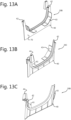
- FIGS 3 and 4 show perspective views from opposite sides. Depicted is an gutter closing piece 30 that can be fitted to an end of the gutter 1 in order to close it. In the figures 3 and 4 , furthermore a gutter coupling piece 20 is depicted, for coupling two ends of gutter butted together.
- Gutter closing piece 30 comprises an end plate 31 matching the shape of the cross section of a gutter 1.
- a closing piece flange 32 extends from the end plate 31.
- the end plate 31 at the closing piece side in an embodiment is provided with adhesive, for instance resulting from an applied double sided tape end.
- the shape of the closing piece flange is adapted to tightly fit the building side inner wall 11, the outer side inner wall 10 and the gutter bottom 8.
- the closing piece flange 32 has a coupling surface which in use contacts the inner surface of the gutter 1 for providing additional attachment or sealing.
- the coupling surface is provided with a rubber sealing strip. In used, this rubber sealing strip is between the coupling surface and the inner surface of the gutter 1. Usually, such a rubber strip will be slightly compressed for improved sealing.
- the coupling surface is provided with an adhesive for attaching the closing piece flange 32 to the inner surface of the gutter 1.
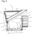
- FIG. 5 and 6 it is illustrated how two ends of gutter 1 or gutter ends are connected using a mitre joint.
- Jointing rods 40 that are here 90 degree angles, i.e., corresponding to the angle of the mitre joint, having a cross section dimensioned and fitting the tubular profiles 16 are inserted in the tubular profiles 16 of one of the gutter ends.
- Double sided tape end is fitted to one of the butt ends of a gutter end.
- the gutter ends are pressed together with the other ends of the joining rods 40 inserting the tubular profiles 16 of the opposite gutter end. Once pressed together, a tape end can applied to the inner surface or channel side and over the mitre joint 26.
- a further joining rod 40 can be fitted in the joined outer side gutter edge groves 17. Yet a further joining rod 40 can be fitted in the building side gutter edge groove 21.
- a corner reinforcement bar 50 is shown. This bar can for instance be applied when a ready-to-fit gutter is transported to a building site,
- the corned reinforcement bar 50 at its ends comprises fitting ends that fit into the respective building side gutter edge groove.
- These fitting ends 51 are at an opposite angle with respect to a longitudinal axis of the reinforcement bar 50.
- both fitting ends are at 45 degrees and thus mutually at 90 degrees.
- the corner reinforcement bar 50 is temporary.
- Gutter reinforcement brace 60 for a gutter 1 is depicted.
- Such a reinforcement brace 60 can be applied at for instance 50 cm interspacing along the length of a gutter 1. This reinforces a gutter 1, for instance in case of heavy snowfall. In an embodiment, these reinforcement braces can be applied in winter.
- Gutter reinforcement brace 60 comprises a gutter brace lever 61 and a gutter brace bar 62.
- Gutter brace lever 61 is hingingly connected to gutter brace bar 62. The connection allows the gutter brace lever 62 and the gutter brace bar 61 to form a scissor mechanism.
- the gutter reinforcement brace 60 can clamp on the inner flange 23 described earlier on/near one gutter edge 9 and clamp on a flange and top surface on the opposite gutter edge.
- the length of the gutter reinforcement brace 60 is dimensioned to the width of the gutter 1.
- one end of the gutter brace lever 61 engages the inner flange 23 at the bottom side and the corresponding end of the gutter brace bar 62 engages the opposite side of the inner flange 23.
- the opposite end of the gutter brace lever 61 engages the upper side of gutter edge 9 and the corresponding end of the gutter brace bar 61 engages a further inner flange 26. It is evident that operation can be reversed, with the gutter reinforcement brace 60 rotated.
- the gutter brace bar 62 and gutter brace lever 61 snap together.
- the gutter 1 will have additional reinforcement.
- the depicted gutter 1 of these embodiments has an alternative gutter edge strip 27. It snaps onto the gutter edge 9 via a small longitudinally extending slot and notch, and a flange snapping behind a profile.
- the gutter edge strip 27 has a decorative aspect, and provides an engagement surface for the gutter brace lever engagement surface 64.
- a gutter coupling assembly 20A, 20B is depicted.
- Such a gutter coupling assembly 20A, 20B allows a (longitudinal, water) coupling of two gutter ends 1.
- the depicted gutter ends (or “ends of gutter (1)”) 1 correspond to the gutter 1 of figure 1 .
- ends of gutter (1) correspond to the gutter 1 of figure 1 .
- the provided coupling assembly 20A, 20B allows a longitudinal change in gutter end distance.
- a gutter (1) can be 3-15 meters long, in practice a gutter (1) can be 3-8 meter long. In extreme circumstances, lengths due to temperature changes may change 1-5 cm.
- the gutter coupling assembly 20A, 20B comprises two cooperating gutter coupling parts 20A, 20B.
- Each of the gutter coupling parts 20A, 20B has a gutter coupling means for coupling the respective gutter coupling part 20A, 20B to a gutter end.
- the gutter coupling parts 20A, 20B comprise a gutter coupling attachment flange 43.
- each gutter coupling part 20A, 20B comprises a complementary coupling means for coupling the gutter coupling parts 20A, 20B.
- one gutter coupling part 20A comprises a gutter coupling flange 41 and the complementary gutter coupling part 20B in the depicted embodiment comprises a gutter coupling sealing flange 42.
- This sealing flange comprises a sealing part comprising in the depicted embodiment a trench for holding a sealing rubber strip.
- the gutter coupling means of the gutter coupling parts 20A, 20B each comprises a gutter coupling plate 40.
- the gutter coupling plates have a shape matching a cross section of the gutter (1).
- a connecting side of the gutter coupling plates 40 can be provided with an adhesive of for instance with a double sided tape part.
- the gutter coupling attachment flanges 43 rest with a gutter side against the inner surface of its gutter 1. The dotted arrows extending try to visualize this.
- the gutter side of the gutter coupling attachment flange 43 can be attached to the inner surface of the gutter (1) by means of an adhesive or a double sided tape.
- the gutter side of the gutter coupling attachment flange 43 can be provided with a sealing rubber strip.
- gutter side of the gutter coupling attachment flange 43 matches the inner surface of the gutter (1).
- the gutter coupling attachment flange 43 extends between 0.5 and 5 cm. In general, it extends between 1 and 3 cm.
- the gutter coupling plate 40 on its connecting side has the gutter coupling attachment flange 43 attached to it, extending from it. At its opposite side, the gutter coupling plate 40 has attached to it the gutter coupling flange 41.
- the cutter coupling sealing flange 42 is attached or injected onto or together with the gutter coupling plate 40. It is provided on the gutter coupling plate 40 in such a way that the sealing surface of the gutter coupling sealing flange 42 is functionally continuous or flush with an inner surface of the gutter coupling attachment flange 43.
- the gutter coupling sealing flange 42 provides a trench for holding a rubber sealing strip (not depicted).
- an gutter side surface of the gutter coupling flange 41 is flush with the inner surface of gutter coupling attachment flange 43, or even a little elevated to be able to slide.
- the gutter coupling flange can extend between 5-10 cm from the gutter coupling plate 40.
- the gutter coupling assembly in an embodiment further comprises the earlier-described gutter coupling cladding profile 28. Usually, it will be around 5-30 cm long. It is to cover the gap (distance between adjacent gutter ends) filled with the gutter coupling parts 20A, 2B. It will be attached to one of the gutter ends 1. For instance, it may be attached using adhesive, of for instance via a mechanical connection, for instance using screws.
- Water sensor 100 comprises a housing 102 allowing attachment to the gutter 1.
- the housing comprises an attachment means for snap-coupling on further inner flange or rail 26.
- the housing 102 may for instance snap fit on the rail 26 and the gutter edge strip 27.
- the water sensor can be attached to the gutter 1 via adhesive or a mechanical attachment lite s screw.
- the water sensor comprises a sensor part 103 that indicates when a water level reaches a predetermined height wh.
- the water sensor issues a signal when this water level wh remains for a predetermined amount of time. For instance, it can measure starting from the first measurement time and measure at fixed time intervals to determine if the water level wh remains. If the water level wh remains at or above the pre-set water level wh, the water sensor can issue a wireless signal indicating clogging of the gutter 1.
- the water sensor 100 comprises a power source, for instance comprising a photovoltaic panel 101.
- the wireless signal mar be transmitted using Bluetooth, Wi-Fi, ZigBee, or any similar signal processing method and protocol.
- the sensor part 103 is for instance set at a water level wh.
- each gutter end is provided with a gutter coupling part similar to the earlier explained gutter coupling part 20B. and it mirror image 20C. (plane mirror image).
- these gutter coupling parts 20B, 20C comprise a gutter coupling plate 40. It has an outer boundary matching a straight (with respect to the longitudinal direction) cross section of the gutter 1.
- the gutter coupling plate 40 at its side which in use is directed towards its respective gutter end can be provided with an adhesive layer for attaching it to its respective gutter end. A double side tape can be used.
- the gutter coupling attachment flange or collar 43 helps in aligning of the gutter coupling plate 40 to the gutter end, and/or prevents static load. It is provided on the gutter end side or adhesive surface 70 - side of gutter coupling plate 40.
- the gutter coupling plate 40 further supports the gutter coupling sealing flange or collar 42.
- This sealing flange of collar 42 provides a small gutter that holds or supports a sealing strip (not shown) that extends only 1-3 mm above the gutter inner surface once the gutter coupling part 20B, 20C is mounted to its gutter end.
- This sealing strip is from a resilient, compressible rubber.
- the sealing strip may be coated with a smoothening coating to reduce wear, explained later.
- the gutter coupling cover plate 80 has a gutter coupling cover plate inner surface 81 and a gutter coupling cover plate outer surface 82
- the gutter coupling cover plate 80 further has gutter coupling cover plate limit rib 84 that is placed between the gutter coupling parts 20B, 20C. It prevents the cover plate 80 from "walking away” after many instances of expansion and contraction of the gutters 1, as the limit rib 84 will remain between the coupling parts 20B, 20C.
Landscapes
- Engineering & Computer Science (AREA)
- Architecture (AREA)
- Civil Engineering (AREA)
- Structural Engineering (AREA)
- Sewage (AREA)
- Roof Covering Using Slabs Or Stiff Sheets (AREA)
Claims (6)
- Eine Dachrinnenanordnung, umfassend eine Dachrinne (1), die in einem Verfahren hergestellt wird, das aus Extrusion und additiver Fertigung ausgewählt ist, und das im Wesentlichen aus einem Polymermaterial, vorzugsweise aus PVC, besteht, wobei die Dachrinne eine Gebäudeseite (B) und eine gegenüberliegende Außenseite (O) umfasst, wobei die Dachrinne (1) doppelwandig ist und eine Innenwand (2) und eine Außenwand (3) sowie Rippen (4) umfasst, die die Innenwand (2) und die Außenwand (3) verbinden und so eine funktionell selbsttragende Dachrinne (1) versorgen, undeine Dachrinnenverstärkungsstrebe (60),wobei die Dachrinne an der Oberkante einer Gebäudeseite (B) und die Dachrinne an der Oberkante der Außenseite (O) Befestigungsvorrichtungen umfasst, insbesondere durchgehende Schienen oder Flansche, zum Anbringen einer das Gebäudeseite und/mit die Außenseite (O) verbindenden Dachrinnenverstärkungsstrebe (60),wobei die Dachrinnenverstärkungsstrebe (60) einen Dachrinnenstützenhebel (61) und eine Dachrinnenstützenstange (62) umfasst, wobei der Dachrinnenstützenhebel (61) gelenkig mit der Dachrinnenstützenstange (62) verbunden ist, wodurch der Dachrinnenstützenstange (62) und die Dachrinnenstützenhebel (61) einen Scherenmechanismus bilden, der es ermöglicht, die Dachrinnenverstärkungsstrebe (60) so zu positionieren, dass die Enden (63, 66) der Dachrinnenstützenstange (62) die Dachrinne angreifen (1) wobei der Dachrinnenstützenhebel (61) und die Dachrinnenstützenstange (62) auseinandergeklappt sind und wenn der Dachrinnenstützenhebel (61) und die Dachrinnenstützenstange (62) in eine Linie gebracht werden, es möglich wird dass die Enden (64, 65) der Dachrinnenstützenhebel (61) auch mit der Dachrinne in Eingriff kommen, wobei ein Teil der Dachrinne zwischen den beiden gegenüberliegenden Enden (63, 64; 65, 66) des Dachrinnenstützenhebels (61) und der Dachrinnenstützenstange (62) eingeklemmt wird, wobei die Dachrinnenstützenhebel (61) und Dachrinnenstützenstange (62) im Wesentlichen die gleiche Länge aufwiesen, im Wesentlichen mit einer Breite der Dachrinne (1) übereinkommen.
- Dachrinnenanordnung nach Anspruch 1, wobei die Dachrinne (1) einen Innenflansch (23) nahe einer Kante ihrer Gebäudeseite (B) und einen weiteren Innenflansch (26) nahe einer Kante ihrer Außenseite aufweist, die einen Eingriff ermöglicht für die Dachrinnenverstärkungsstrebe (60), insbesondere sind der Innenflansch und der weitere Innenflansch hinterschnitten und öffnen sich zum Boden der Dachrinne hin oder biegen sich zum Boden der Dachrinne hin.
- Dachrinnenanordnung nach Anspruch 2, bei der die Dachrinnenverstärkungsstrebe (60) so ausgelegt ist, dass sie den Innenflansch (23) an/in der Nähe einer Dachrinnenkante (9) festklemmt und sich festklemmt an den weiteren Innenflansch (26) und/oder an die obere Oberfläche der gegenüberliegenden Dachrinne Rand, wobei die Länge der Dachrinnenverstärkung (60) auf die Breite der Dachrinne (1) abgestimmt ist.
- Dachrinnenanordnung nach einer den Ansprüchen 1 - 3, wobei wenn der Dachrinnenstützenhebel (61) und die Dachrinnenstützenstange (62) in eine Linie gebracht werden ein Ende der Dachrinnenstützenhebel (61) angreift an der Bodenseite des Innenflansches (23), und das entsprechende Ende des Dachrinnenstützenstange (62) angreift an der gegenüberliegende Seite des Innenflansches (23), und den gegenüberliegende Ende der Dachrinnenstützenhebel (61) angreift an der Oberseite der Dachrinnenkante (9) und das entsprechenden Ende der Dachrinnenstützenstange (62) eingreift in den weiteren Innenflansch (26), wobei wenn in Linie die Dachrinnenstützenstange (62) und der Dachrinnenstützenhebel (61) ineinander einrasten, so dass wenn eine Dachrinne beispielsweise mit Schnee beladen wird, die Dachrinne (1) verfügt über eine zusätzliche Verstärkung.
- Dachrinnenanordnung nach einem der vorhergehenden Ansprüche, wobei zur Befestigung der Dachrinne (1) an einem Gebäude die Dachrinnenbaugruppe (1) eine Befestigungsschiene aufweist, dass eine Montageausnehmung (6) in dem Außenwandteil (5) umfasst und eine Montageschiene (7) dass einen Montagesteg (14) aufweist dass an die Befestigungsschiene passt.
- Dachrinnenanordnung nach Anspruch 5, wobei die Montageausnehmung (6) eine unterschnittene Nut umfasst und die Montageschiene (7) einen U-förmigen Rand aufweist, der passt, insbesondere einrastet, in der unterschnittene Nut der Montageaussparung (6).
Applications Claiming Priority (1)
| Application Number | Priority Date | Filing Date | Title |
|---|---|---|---|
| EP20202162.2A EP3985193B1 (de) | 2020-10-15 | 2020-10-15 | Dachrinnenbau |
Publications (2)
| Publication Number | Publication Date |
|---|---|
| EP3985196A1 EP3985196A1 (de) | 2022-04-20 |
| EP3985196B1 true EP3985196B1 (de) | 2025-03-12 |
Family
ID=73005293
Family Applications (4)
| Application Number | Title | Priority Date | Filing Date |
|---|---|---|---|
| EP20202162.2A Active EP3985193B1 (de) | 2020-10-15 | 2020-10-15 | Dachrinnenbau |
| EP21203044.9A Active EP3985195B1 (de) | 2020-10-15 | 2021-10-15 | Regenrinne |
| EP21203045.6A Active EP3985196B1 (de) | 2020-10-15 | 2021-10-15 | Regenrinne |
| EP21203043.1A Active EP3985194B1 (de) | 2020-10-15 | 2021-10-15 | Regenrinnenbau |
Family Applications Before (2)
| Application Number | Title | Priority Date | Filing Date |
|---|---|---|---|
| EP20202162.2A Active EP3985193B1 (de) | 2020-10-15 | 2020-10-15 | Dachrinnenbau |
| EP21203044.9A Active EP3985195B1 (de) | 2020-10-15 | 2021-10-15 | Regenrinne |
Family Applications After (1)
| Application Number | Title | Priority Date | Filing Date |
|---|---|---|---|
| EP21203043.1A Active EP3985194B1 (de) | 2020-10-15 | 2021-10-15 | Regenrinnenbau |
Country Status (2)
| Country | Link |
|---|---|
| EP (4) | EP3985193B1 (de) |
| NL (3) | NL2029442B1 (de) |
Family Cites Families (22)
| Publication number | Priority date | Publication date | Assignee | Title |
|---|---|---|---|---|
| GB2066872B (en) * | 1979-12-24 | 1983-08-10 | Paragon Plastics Ltd | Rainwater gutter attachment bracket |
| JPH0348356Y2 (de) * | 1986-06-30 | 1991-10-16 | ||
| US4727689A (en) * | 1986-08-28 | 1988-03-01 | Kusan, Inc. | Detachable rain gutter |
| JP2531166Y2 (ja) * | 1991-09-30 | 1997-04-02 | 積水化学工業株式会社 | 軒樋の内面接続構造 |
| DE9207858U1 (de) * | 1992-06-12 | 1992-09-10 | Schlutz, Guenter, 3501 Naumburg | Dachrinne |
| NL194090C (nl) | 1992-12-14 | 2001-06-05 | Ubbink Nederland Bv | Samenstel van een hellend dak en een dakgoot, alsmede dakgoot. |
| JPH06307038A (ja) * | 1993-04-27 | 1994-11-01 | Sekisui Chem Co Ltd | 軒樋継手 |
| JPH08246623A (ja) * | 1995-03-08 | 1996-09-24 | Sekisui Chem Co Ltd | 軒樋支持具 |
| JPH09317105A (ja) * | 1996-05-29 | 1997-12-09 | Sekisui Chem Co Ltd | 軒樋支持具 |
| GB9706826D0 (en) | 1997-04-04 | 1997-05-21 | Marley Extrusions | Gutters |
| EP0971083B1 (de) * | 1998-07-09 | 2004-02-04 | Ubbink B.V. | Kupplungsstück für Dachrinnen |
| JP2002227358A (ja) * | 2001-01-31 | 2002-08-14 | Sekisui Chem Co Ltd | 軒樋の接続構造 |
| JP3921077B2 (ja) * | 2001-11-13 | 2007-05-30 | 株式会社野島角清製作所 | 樋受具 |
| JP3929318B2 (ja) * | 2002-01-31 | 2007-06-13 | 株式会社オーティス | 縱回転ロック式の雨樋支持具 |
| CA2395740A1 (en) * | 2002-07-26 | 2004-01-26 | Royal Group Technologies Limited | Plastic gutter system and components thereof |
| JP5337476B2 (ja) * | 2008-12-26 | 2013-11-06 | 株式会社オーティス | 樋支持具 |
| JP5503227B2 (ja) * | 2009-08-31 | 2014-05-28 | タキロン株式会社 | 軒樋伸縮継手の位置決め具 |
| JP2012062643A (ja) * | 2010-09-14 | 2012-03-29 | Yusuke Ohira | 雨樋内の堆積物排出装置 |
| FR3039574A1 (fr) * | 2015-07-22 | 2017-02-03 | Christian Alexis Raymond Mignot | Rive goutt |
| AU2019317218B2 (en) * | 2018-08-07 | 2021-10-21 | Rain Hail Solutions Pty Ltd | A system for a roof gutter |
| CN209760620U (zh) * | 2019-04-04 | 2019-12-10 | 沈阳天华建筑设计有限公司 | 一种建筑设计屋顶檐口防水装置 |
| CN111648536B (zh) * | 2020-06-29 | 2021-05-04 | 海通建设集团有限公司 | 双曲面金属屋面的天沟结构 |
-
2020
- 2020-10-15 EP EP20202162.2A patent/EP3985193B1/de active Active
-
2021
- 2021-10-15 EP EP21203044.9A patent/EP3985195B1/de active Active
- 2021-10-15 EP EP21203045.6A patent/EP3985196B1/de active Active
- 2021-10-15 NL NL2029442A patent/NL2029442B1/en active
- 2021-10-15 NL NL2029443A patent/NL2029443B1/en active
- 2021-10-15 NL NL2029441A patent/NL2029441B1/en active
- 2021-10-15 EP EP21203043.1A patent/EP3985194B1/de active Active
Also Published As
| Publication number | Publication date |
|---|---|
| EP3985194A2 (de) | 2022-04-20 |
| EP3985194B1 (de) | 2025-05-21 |
| NL2029441A (en) | 2022-06-08 |
| EP3985195A2 (de) | 2022-04-20 |
| NL2029441B1 (en) | 2023-05-19 |
| EP3985195B1 (de) | 2023-08-02 |
| NL2029442A (en) | 2022-06-08 |
| NL2029443A (en) | 2022-06-08 |
| EP3985193C0 (de) | 2025-06-04 |
| EP3985196A1 (de) | 2022-04-20 |
| NL2029443B1 (en) | 2023-04-17 |
| EP3985193B1 (de) | 2025-06-04 |
| EP3985194C0 (de) | 2025-05-21 |
| EP3985194A3 (de) | 2022-06-15 |
| EP3985195A3 (de) | 2022-06-15 |
| EP3985193A1 (de) | 2022-04-20 |
| NL2029442B1 (en) | 2023-05-15 |
Similar Documents
| Publication | Publication Date | Title |
|---|---|---|
| US12473733B1 (en) | Systems for forming a pitched roof section or wall with the use of solar panels | |
| US8584424B2 (en) | Wall and skylight panel system with attachment clip | |
| US6640508B2 (en) | Roof window assembly and components | |
| US5239791A (en) | Adjustable coping assembly | |
| US6195948B1 (en) | Skylights to accommodate on site adjustments for variations in installations | |
| JPH07501862A (ja) | 天窓(スカイライト)アセンブリ | |
| EP3680416B1 (de) | Verbindungselement für eine abdeckungsanordnung zur verwendung in einer dachfensteranordnung und verfahren zum abdichten einer dachfensteranordnung | |
| CN205663119U (zh) | 在用于并排安装的屋顶窗户的防水组件中使用的连接器元件 | |
| EP2472029B1 (de) | Verfahren zur Befestigung eines Dichtungselementes eines Dachfensters und Dichtungssystem für ein Dachfenster | |
| US7017307B2 (en) | Structures | |
| HU215339B (hu) | Takarólemez-elrendezés tetőelemek, főleg tetőablakok tetőszerkezetbe építéséhez | |
| EP3985196B1 (de) | Regenrinne | |
| US6272812B1 (en) | Glazed roof construction | |
| GB2164369A (en) | Verge capping system | |
| US20070094999A1 (en) | Construction of convservatory roofs | |
| EP2171170A2 (de) | System zum anbringen von fensterrollläden an einem wintergartendach | |
| EP0538379B1 (de) | Gewächshauskonstruktion | |
| WO2006000760A1 (en) | Improvements in and relating to construction of conservatory roofs | |
| GB2304130A (en) | Gutter systems | |
| WO2006000782A1 (en) | Conservatory roofs | |
| NO347336B1 (en) | Corner profile and corner profile assembly for locking vertical panels in an internal corner | |
| EP1780349A2 (de) | Dachzubehör | |
| WO2002053857A1 (en) | A glazing bar assembly for glazed structures | |
| CA2299220A1 (en) | Glazed roof construction | |
| JPH054508B2 (de) |
Legal Events
| Date | Code | Title | Description |
|---|---|---|---|
| PUAI | Public reference made under article 153(3) epc to a published international application that has entered the european phase |
Free format text: ORIGINAL CODE: 0009012 |
|
| STAA | Information on the status of an ep patent application or granted ep patent |
Free format text: STATUS: THE APPLICATION HAS BEEN PUBLISHED |
|
| AK | Designated contracting states |
Kind code of ref document: A1 Designated state(s): AL AT BE BG CH CY CZ DE DK EE ES FI FR GB GR HR HU IE IS IT LI LT LU LV MC MK MT NL NO PL PT RO RS SE SI SK SM TR |
|
| STAA | Information on the status of an ep patent application or granted ep patent |
Free format text: STATUS: REQUEST FOR EXAMINATION WAS MADE |
|
| 17P | Request for examination filed |
Effective date: 20221019 |
|
| RBV | Designated contracting states (corrected) |
Designated state(s): AL AT BE BG CH CY CZ DE DK EE ES FI FR GB GR HR HU IE IS IT LI LT LU LV MC MK MT NL NO PL PT RO RS SE SI SK SM TR |
|
| GRAP | Despatch of communication of intention to grant a patent |
Free format text: ORIGINAL CODE: EPIDOSNIGR1 |
|
| STAA | Information on the status of an ep patent application or granted ep patent |
Free format text: STATUS: GRANT OF PATENT IS INTENDED |
|
| RIC1 | Information provided on ipc code assigned before grant |
Ipc: E04D 13/064 20060101ALN20230908BHEP Ipc: E04D 13/072 20060101ALI20230908BHEP Ipc: E04D 13/068 20060101AFI20230908BHEP |
|
| INTG | Intention to grant announced |
Effective date: 20231013 |
|
| GRAJ | Information related to disapproval of communication of intention to grant by the applicant or resumption of examination proceedings by the epo deleted |
Free format text: ORIGINAL CODE: EPIDOSDIGR1 |
|
| STAA | Information on the status of an ep patent application or granted ep patent |
Free format text: STATUS: REQUEST FOR EXAMINATION WAS MADE |
|
| INTC | Intention to grant announced (deleted) | ||
| RIC1 | Information provided on ipc code assigned before grant |
Ipc: E04D 13/064 20060101ALN20240213BHEP Ipc: E04D 13/072 20060101ALI20240213BHEP Ipc: E04D 13/068 20060101AFI20240213BHEP |
|
| GRAP | Despatch of communication of intention to grant a patent |
Free format text: ORIGINAL CODE: EPIDOSNIGR1 |
|
| STAA | Information on the status of an ep patent application or granted ep patent |
Free format text: STATUS: GRANT OF PATENT IS INTENDED |
|
| INTG | Intention to grant announced |
Effective date: 20240402 |
|
| RIC1 | Information provided on ipc code assigned before grant |
Ipc: E04D 13/064 20060101ALN20240321BHEP Ipc: E04D 13/072 20060101ALI20240321BHEP Ipc: E04D 13/068 20060101AFI20240321BHEP |
|
| GRAS | Grant fee paid |
Free format text: ORIGINAL CODE: EPIDOSNIGR3 |
|
| GRAJ | Information related to disapproval of communication of intention to grant by the applicant or resumption of examination proceedings by the epo deleted |
Free format text: ORIGINAL CODE: EPIDOSDIGR1 |
|
| GRAL | Information related to payment of fee for publishing/printing deleted |
Free format text: ORIGINAL CODE: EPIDOSDIGR3 |
|
| STAA | Information on the status of an ep patent application or granted ep patent |
Free format text: STATUS: REQUEST FOR EXAMINATION WAS MADE |
|
| INTC | Intention to grant announced (deleted) | ||
| GRAP | Despatch of communication of intention to grant a patent |
Free format text: ORIGINAL CODE: EPIDOSNIGR1 |
|
| STAA | Information on the status of an ep patent application or granted ep patent |
Free format text: STATUS: GRANT OF PATENT IS INTENDED |
|
| RIC1 | Information provided on ipc code assigned before grant |
Ipc: E04D 13/064 20060101ALN20240830BHEP Ipc: E04D 13/072 20060101ALI20240830BHEP Ipc: E04D 13/068 20060101AFI20240830BHEP |
|
| INTG | Intention to grant announced |
Effective date: 20241002 |
|
| GRAS | Grant fee paid |
Free format text: ORIGINAL CODE: EPIDOSNIGR3 |
|
| GRAA | (expected) grant |
Free format text: ORIGINAL CODE: 0009210 |
|
| STAA | Information on the status of an ep patent application or granted ep patent |
Free format text: STATUS: THE PATENT HAS BEEN GRANTED |
|
| AK | Designated contracting states |
Kind code of ref document: B1 Designated state(s): AL AT BE BG CH CY CZ DE DK EE ES FI FR GB GR HR HU IE IS IT LI LT LU LV MC MK MT NL NO PL PT RO RS SE SI SK SM TR |
|
| REG | Reference to a national code |
Ref country code: GB Ref legal event code: FG4D |
|
| REG | Reference to a national code |
Ref country code: CH Ref legal event code: EP |
|
| REG | Reference to a national code |
Ref country code: DE Ref legal event code: R096 Ref document number: 602021027434 Country of ref document: DE |
|
| REG | Reference to a national code |
Ref country code: IE Ref legal event code: FG4D |
|
| REG | Reference to a national code |
Ref country code: NL Ref legal event code: FP |
|
| PG25 | Lapsed in a contracting state [announced via postgrant information from national office to epo] |
Ref country code: RS Free format text: LAPSE BECAUSE OF FAILURE TO SUBMIT A TRANSLATION OF THE DESCRIPTION OR TO PAY THE FEE WITHIN THE PRESCRIBED TIME-LIMIT Effective date: 20250612 |
|
| PG25 | Lapsed in a contracting state [announced via postgrant information from national office to epo] |
Ref country code: FI Free format text: LAPSE BECAUSE OF FAILURE TO SUBMIT A TRANSLATION OF THE DESCRIPTION OR TO PAY THE FEE WITHIN THE PRESCRIBED TIME-LIMIT Effective date: 20250312 |
|
| PG25 | Lapsed in a contracting state [announced via postgrant information from national office to epo] |
Ref country code: ES Free format text: LAPSE BECAUSE OF FAILURE TO SUBMIT A TRANSLATION OF THE DESCRIPTION OR TO PAY THE FEE WITHIN THE PRESCRIBED TIME-LIMIT Effective date: 20250312 |
|
| REG | Reference to a national code |
Ref country code: LT Ref legal event code: MG9D |
|
| PG25 | Lapsed in a contracting state [announced via postgrant information from national office to epo] |
Ref country code: NO Free format text: LAPSE BECAUSE OF FAILURE TO SUBMIT A TRANSLATION OF THE DESCRIPTION OR TO PAY THE FEE WITHIN THE PRESCRIBED TIME-LIMIT Effective date: 20250612 |
|
| PG25 | Lapsed in a contracting state [announced via postgrant information from national office to epo] |
Ref country code: HR Free format text: LAPSE BECAUSE OF FAILURE TO SUBMIT A TRANSLATION OF THE DESCRIPTION OR TO PAY THE FEE WITHIN THE PRESCRIBED TIME-LIMIT Effective date: 20250312 |
|
| PG25 | Lapsed in a contracting state [announced via postgrant information from national office to epo] |
Ref country code: LV Free format text: LAPSE BECAUSE OF FAILURE TO SUBMIT A TRANSLATION OF THE DESCRIPTION OR TO PAY THE FEE WITHIN THE PRESCRIBED TIME-LIMIT Effective date: 20250312 |
|
| PG25 | Lapsed in a contracting state [announced via postgrant information from national office to epo] |
Ref country code: BG Free format text: LAPSE BECAUSE OF FAILURE TO SUBMIT A TRANSLATION OF THE DESCRIPTION OR TO PAY THE FEE WITHIN THE PRESCRIBED TIME-LIMIT Effective date: 20250312 Ref country code: GR Free format text: LAPSE BECAUSE OF FAILURE TO SUBMIT A TRANSLATION OF THE DESCRIPTION OR TO PAY THE FEE WITHIN THE PRESCRIBED TIME-LIMIT Effective date: 20250613 |
|
| REG | Reference to a national code |
Ref country code: AT Ref legal event code: MK05 Ref document number: 1775115 Country of ref document: AT Kind code of ref document: T Effective date: 20250312 |
|
| PG25 | Lapsed in a contracting state [announced via postgrant information from national office to epo] |
Ref country code: SE Free format text: LAPSE BECAUSE OF FAILURE TO SUBMIT A TRANSLATION OF THE DESCRIPTION OR TO PAY THE FEE WITHIN THE PRESCRIBED TIME-LIMIT Effective date: 20250312 |
|
| PG25 | Lapsed in a contracting state [announced via postgrant information from national office to epo] |
Ref country code: SM Free format text: LAPSE BECAUSE OF FAILURE TO SUBMIT A TRANSLATION OF THE DESCRIPTION OR TO PAY THE FEE WITHIN THE PRESCRIBED TIME-LIMIT Effective date: 20250312 |
|
| PG25 | Lapsed in a contracting state [announced via postgrant information from national office to epo] |
Ref country code: PT Free format text: LAPSE BECAUSE OF FAILURE TO SUBMIT A TRANSLATION OF THE DESCRIPTION OR TO PAY THE FEE WITHIN THE PRESCRIBED TIME-LIMIT Effective date: 20250714 |
|
| PG25 | Lapsed in a contracting state [announced via postgrant information from national office to epo] |
Ref country code: IT Free format text: LAPSE BECAUSE OF FAILURE TO SUBMIT A TRANSLATION OF THE DESCRIPTION OR TO PAY THE FEE WITHIN THE PRESCRIBED TIME-LIMIT Effective date: 20250312 Ref country code: PL Free format text: LAPSE BECAUSE OF FAILURE TO SUBMIT A TRANSLATION OF THE DESCRIPTION OR TO PAY THE FEE WITHIN THE PRESCRIBED TIME-LIMIT Effective date: 20250312 |
|
| PG25 | Lapsed in a contracting state [announced via postgrant information from national office to epo] |
Ref country code: AT Free format text: LAPSE BECAUSE OF FAILURE TO SUBMIT A TRANSLATION OF THE DESCRIPTION OR TO PAY THE FEE WITHIN THE PRESCRIBED TIME-LIMIT Effective date: 20250312 |
|
| PG25 | Lapsed in a contracting state [announced via postgrant information from national office to epo] |
Ref country code: CZ Free format text: LAPSE BECAUSE OF FAILURE TO SUBMIT A TRANSLATION OF THE DESCRIPTION OR TO PAY THE FEE WITHIN THE PRESCRIBED TIME-LIMIT Effective date: 20250312 Ref country code: EE Free format text: LAPSE BECAUSE OF FAILURE TO SUBMIT A TRANSLATION OF THE DESCRIPTION OR TO PAY THE FEE WITHIN THE PRESCRIBED TIME-LIMIT Effective date: 20250312 |
|
| PG25 | Lapsed in a contracting state [announced via postgrant information from national office to epo] |
Ref country code: RO Free format text: LAPSE BECAUSE OF FAILURE TO SUBMIT A TRANSLATION OF THE DESCRIPTION OR TO PAY THE FEE WITHIN THE PRESCRIBED TIME-LIMIT Effective date: 20250312 |
|
| PG25 | Lapsed in a contracting state [announced via postgrant information from national office to epo] |
Ref country code: SK Free format text: LAPSE BECAUSE OF FAILURE TO SUBMIT A TRANSLATION OF THE DESCRIPTION OR TO PAY THE FEE WITHIN THE PRESCRIBED TIME-LIMIT Effective date: 20250312 |
|
| PG25 | Lapsed in a contracting state [announced via postgrant information from national office to epo] |
Ref country code: IS Free format text: LAPSE BECAUSE OF FAILURE TO SUBMIT A TRANSLATION OF THE DESCRIPTION OR TO PAY THE FEE WITHIN THE PRESCRIBED TIME-LIMIT Effective date: 20250712 |
|
| PGFP | Annual fee paid to national office [announced via postgrant information from national office to epo] |
Ref country code: NL Payment date: 20251030 Year of fee payment: 5 |
|
| REG | Reference to a national code |
Ref country code: DE Ref legal event code: R097 Ref document number: 602021027434 Country of ref document: DE |
|
| PG25 | Lapsed in a contracting state [announced via postgrant information from national office to epo] |
Ref country code: DK Free format text: LAPSE BECAUSE OF FAILURE TO SUBMIT A TRANSLATION OF THE DESCRIPTION OR TO PAY THE FEE WITHIN THE PRESCRIBED TIME-LIMIT Effective date: 20250312 |
|
| PLBE | No opposition filed within time limit |
Free format text: ORIGINAL CODE: 0009261 |
|
| STAA | Information on the status of an ep patent application or granted ep patent |
Free format text: STATUS: NO OPPOSITION FILED WITHIN TIME LIMIT |
|
| REG | Reference to a national code |
Ref country code: CH Ref legal event code: L10 Free format text: ST27 STATUS EVENT CODE: U-0-0-L10-L00 (AS PROVIDED BY THE NATIONAL OFFICE) Effective date: 20260121 |
|
| 26N | No opposition filed |
Effective date: 20251215 |