EP3985152B1 - Flechtmaschine - Google Patents
Flechtmaschine Download PDFInfo
- Publication number
- EP3985152B1 EP3985152B1 EP19759630.7A EP19759630A EP3985152B1 EP 3985152 B1 EP3985152 B1 EP 3985152B1 EP 19759630 A EP19759630 A EP 19759630A EP 3985152 B1 EP3985152 B1 EP 3985152B1
- Authority
- EP
- European Patent Office
- Prior art keywords
- plates
- driving
- plate
- group
- machine according
- Prior art date
- Legal status (The legal status is an assumption and is not a legal conclusion. Google has not performed a legal analysis and makes no representation as to the accuracy of the status listed.)
- Active
Links
Images


Classifications
-
- D—TEXTILES; PAPER
- D04—BRAIDING; LACE-MAKING; KNITTING; TRIMMINGS; NON-WOVEN FABRICS
- D04C—BRAIDING OR MANUFACTURE OF LACE, INCLUDING BOBBIN-NET OR CARBONISED LACE; BRAIDING MACHINES; BRAID; LACE
- D04C3/00—Braiding or lacing machines
- D04C3/02—Braiding or lacing machines with spool carriers guided by track plates or by bobbin heads exclusively
- D04C3/24—Devices for controlling spool carriers to obtain patterns, e.g. devices on guides or track plates
- D04C3/30—Devices for controlling spool carriers to obtain patterns, e.g. devices on guides or track plates by controlling switches of guides or track plates
-
- D—TEXTILES; PAPER
- D04—BRAIDING; LACE-MAKING; KNITTING; TRIMMINGS; NON-WOVEN FABRICS
- D04C—BRAIDING OR MANUFACTURE OF LACE, INCLUDING BOBBIN-NET OR CARBONISED LACE; BRAIDING MACHINES; BRAID; LACE
- D04C3/00—Braiding or lacing machines
- D04C3/02—Braiding or lacing machines with spool carriers guided by track plates or by bobbin heads exclusively
- D04C3/14—Spool carriers
- D04C3/18—Spool carriers for vertical spools
-
- D—TEXTILES; PAPER
- D04—BRAIDING; LACE-MAKING; KNITTING; TRIMMINGS; NON-WOVEN FABRICS
- D04C—BRAIDING OR MANUFACTURE OF LACE, INCLUDING BOBBIN-NET OR CARBONISED LACE; BRAIDING MACHINES; BRAID; LACE
- D04C3/00—Braiding or lacing machines
- D04C3/02—Braiding or lacing machines with spool carriers guided by track plates or by bobbin heads exclusively
- D04C3/20—Arrangement of bobbin heads and guides or track plates in the machine
Definitions
- Braiding machine of the type comprising a series of plates arranged in a continuous order in a closed circuit, each plate comprising certain slots that accommodate spindles having a guide; at least a drive means for driving the plates; guide channels where the spindle guides run, and at least two diverter channels having two positions; a first one for continuous rotation by the same plate, and a second position for shifting the plate; characterized in that it comprises: a first group of plates having at least five plates, one of which plates is the driving plate, the first driving plate, arranged one after the other and defining two end plates, having at least four slots in each plate; a second group of plates having two plates, both driving plates, which are arranged after the two end plates, one for each end plate, having at least four slots and both plates, in the two plates; and a third group of plates having a plate that is arranged between the second driving plates, the third driving plate, which closes the circuit, and having at least two slots more than the plates in the second group of plates and, since the two diverter channels are located between
- a first system consists of production with machines that perform a round braiding with an even number of threads. These machines intertwine the threads in the coils by rotating the coils in one direction and rotating the coils in the opposite direction, thus forming what is known as a tubular braided structure. These braids are used for different purposes, for example, ropes for ships, for climbing, etc.
- the second system consists of machines that produce a flat braiding, with an odd number of threads.
- state of the art is Spanish Patent n° 200002978 ( ES2193817), "BRAIDING MACHINE", of 2000, owned by AMERICAN METRIC CORPORATION , concerning a braiding machine formed by a supporting table mounting a plurality of individual segments forming a bed having substantially circular tracking groove.
- Each segment comprises a segment groove which comprises a pair of opposed transfer openings formed through the outer wall, with the transfer openings of adjacent segments being in contact forming the tracking groove as an endless ring.
- the size of the endless ring is determined by the number and size of the segments used.
- the tracking groove may be coated with a selected material other than the material forming the segment.
- the applicant company is the owner of Spanish Patent n° 201531634 ( ES2612143 - WO2017081338) "BRAIDING MACHINE", of 2015 , which comprises supply means which move a number of plates on which spool-carrying mechanisms are disposed, and comprising at least one guide in the form of a figure of eight, inside which a guiding element belonging to the spool-carrying mechanism moves, and a first shaft connected to the supply means, belonging to the plate, and terminating at the top in a first pinion, to which at least one satellite pinion engages, which is in turn engaged with a second pinion belonging to the spool-carrying mechanism, wherein a rotation of the first shaft brings about the rotation of the first pinion, which blocks the satellite pinion, moving same and moves the spool-carrying mechanism according to the path of the guide, with the same face of the spool-carrying mechanism remaining facing a predetermined point of reference during the entire course of the guide.
- British Patent GB611071 refers to a braiding machine wherein the wanderer spindles have a sinuous path imparted thereto by means of a series of driven rotatable notched discs located within an oil bath and having an intermittent change over guide track located at the junction of each disc for the purpose herein stated, and a switch operating device for stopping the operation of the machine in the event of a thread breaking.
- the present invention belongs to the field of braiding machines.
- This invention solves this problem by enabling the switch from flat braiding to round braiding and vice versa almost automatically, and within a few seconds, just the time needed to synchronize flat and round, and vice versa, thus avoiding thread splicing.
- An object of the present invention is a braiding machine of the type comprising a series of plates arranged in a continuous manner in a closed circuit, each plate comprising a number of slots accommodating a number of spindles with a guide, at least one drive means for driving the plates, guide channels where the spindle guides run and at least two diverter channels having two positions, a first position for continuous rotation in one same plate and a second position, for switching plates; characterized in that it comprises: a first group of plates having at least five plates, where one of the plates is a driving plate, the first driving plate, arranged in a continuous manner and two end plates, having at least four slots in each plate, a second group of plates, having two plates, both of which are driving plates, second driving plates, which are located subsequent to the two end plates, one for each end plate, having at least four slots, in both plates and a third group of plates having one plate, fitted in between the second driving plates, driving plate, the third driving plate, closing the circuit, having at least two slots more than the plates of the first
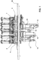
- Figure 1 shows an end plate 5, second driving plates 6, 7, a third driving plate 8, drive means of a first driving plate 13, drive means of the second driving plates 14, 15, drive means of third driving plate 16, drive means of diverter channels 17,18 and a chassis 26.
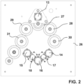
- Figure 2 includes a representation of the drive means of a first driving plate 13, drive means of second driving plates 14, 15, drive means of third driving plate 16, drive means of diverter channels 17,18, chassis 26, a first driving pinion 27, driven pinions 28,29 and end plate pinions 30,31.
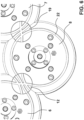
- Figure 3 shows first driving plate 1, driven plates 2,3, end plates 4,5 with their respective slots 9, all of which form the first group of plates, second driving plates 6,7 which form the second group of plates, third driving plate 8 with its respective slots 11 which forms the third group of plates, the first group of plates spindles 20, the second group of plates spindles 23 and switching spindles 24, 25.
- Figure 4 shows the first driving plate 1, driven plates 2, 3, end plates 4, 5 with their slots 9, second driving plates 6, 7 with their slots 10, third driving plate 8 with its slots 11 and switching spindles 24, 25.
- Figure 5 shows first driving plate 1, driven plates 2, 3, end plates 4, 5 with their slots 9, second driving plates 6, 7 with their slots 10, third driving plate 8 with its slots 11, first group of plates spindles 20, second group of plates spindles 23, third group of plates spindles 32 and switching spindles 24, 25.
- Figure 6 shows second driving plates 6, 7, third driving plate 8, diverter channels 12, 19 and guide channels 22.
- Figure 7 shows first driving plate 1, intersection channels 33, a spindle guide 21, first group of plates spindle 20 and guide channels 22.
- Figure 8 shows the end plate with its slots 9, which form the first group of plates, second driving plates 6, 7 with their slots 10 which form the second group of plates, second group of plates spindles 23 y switching spindles 24,25.
- Figure 6 illustrates the two positions of the diverter channels 12, 19, one in each position. This is aimed at facilitating the explanation that will be provided hereafter.
- both diverter channels 12,19 operate, they should be arranged in the same position and not as shown in Figure 6 , that is, the diverter channels should not be each in its own operating position and both should be in the same operating position.
- the two diverter channels should be positioned as shown in the diverter channel 12, and for the flat braiding both diverter channels should be positioned as they are shown in diverter channel 19.
- the braiding machine of the present invention is formed by a series of plates 1-8 that are arranged in a continuous manner, one after the other, forming a closed circuit.
- the plates 1-8 comprise slots 9, which is where the spindles 20 are accommodated with the braiding thread.
- Each one of the spindles 20 has a guide 21, which is arranged inside the guiding channels 22, and the guides 21 move inside the guiding channels 22 ( Figure 7 ).
- the invention comprises at least one drive means that drives the plates 1-8, and at least two diverter channels 12,19 having two positions.
- This embodiment comprises two channels, but the number of channels may be increased if required, to adapt to particular structural needs.
- the positions are: a first position for continuous rotation of the spindle in one same plate and a second position, for the spindle to switch plates; that is, in the first position the spindle keeps rotating within a same plate and in the second position the spindle switches plate.
- the plates are grouped in three groups, having different purposes and different actions, according to whether the braiding is flat or round.
- the first group of plates is made up of a minimum number of five plates 1, 2, 3, 4, 5.
- One of the plates is a driving plate, the first driving plate 1, that is, this driving plate 1 transmits motion to the other plates; driven plates 2, 3 and end plates 4, 5.
- Plates 1, 2, 3, 4, 5 are arranged in a continuous manner and they define the two end plates 4, 5, which are also driven plates.
- plates 1, 2, 3, 4, 5 include at least four slots 9 in each of plates 1, 2, 3, 4, 5.
- the second group of plates is made up of two plates 6, 7, both of which are driving plates, which will hereafter be referred to as second driving plates 6, 7. Both second driving plates are positioned after the two end plates 4, 5, one for each end plate.
- the last group of plates, the third group, is made up of just one plate, a driving plate, the third driving plate 8, which is positioned in between the second driving plates 6, 7, that is, closing the circuit.
- the third driving plate 8 includes at least two slots 11 more than the plates of the first group of plates.
- the two diverter channels 12, 19 are positioned between the second group of plates and the third group of plates.
- the two diverter channels define a first operation position wherein the third driving plate 8 is isolated from the circuit, consistently with the flat braiding and the position shown in the diverter channel 19, that is, it will not carry any spindles; and a second operation position wherein the third driving plate 8 is part of the circuit, consistently with the round braiding, the diverter channel is positioned as shown in the diverter channel 12 and therefore conveys the spindles.
- plates 1, 2, 3, 4, 5 of the first group of plates and plates 6, 7 of the second group of plates include four slots, and plate 8 of the third group of plates includes six slots.
- each driving plate 1, 6, 7, 8 is an independent drive means 13, 14, 15, 16, for example, a servo driver for each driving plate 1, 6, 7, 8.
- each diverter channel 12, 19 comprises an independent drive means 17, 18, for example, servo drivers, that is, to drive the diverter channels 12, 19 between the first operation position and the second operation position and vice versa, as above explained.
- the third driving plate 8 rotates at a lower speed than the second driving plates 6, 7 and the first driving plate 1.
- second driving plates 6, 7 include at some time a spindle 23, 24 in each slot 10 ( Figure 8 ).
- second driving plates 6, 7 move forwards and backwards, as will explained more in detail bellow, and which is illustrated in the three positions in Figure 8 .
- both in the round braiding position and in the flat braiding position seventeen spindles are included: 20, 23, 24, 25.
- a braiding machine can be configured so that eight spindles rotate in one direction and nine spindles rotate in the opposite direction. That is, even in round braiding, braids of an odd number of threads can be produced, whereas round braids are usually made only with an even number of threads.
- the third driving plate 8 can be configured so that the diameter of the third driving plate 8 is the same as the second driving plates 6, 7 and the same diameter as the plates in the first group 1-5.
- plates 1 -8 are arranged in a circle.
- the operator will firstly set the control panel (not shown, commonly known and not part of the claims hereof) according to the type of braiding the machine is to perform. If the operator choses a round braiding, as in Figures 1 , 2 , 5 , 6 and 7 , the process will be as follows: The starting point is that plates 1-7 have four slots in each plate and six slots in the third driving plate 8. The number of slots 11 in the third driving plate 8 may vary according to the number of slots in the remaining plates 1 - 7 and of the particular needs, but the minimum number of slots must be two more slots that in the second driving plates 6, 7.
- the slot configuration also relates to the rotation speed of the third driving plate 8 which, having second driving plates 6, 7 with four slots each, and third driving plates 8 with six slots 11 each, that is in a 2/3 ratio, in turn defines that the rotation speed of the third driving plate 8 is 2/3 the speed of the second driving plates 6, 7, and therefore the ratio is the same ratio between the slots of the second driving plates 6, 7 and the third driving plate 8.
- the configuration of the round braiding in this embodiment includes eight plates. These eight plates include four driving plates, first driving plate 1, which drives the plates in the first group of plates by means of a gear system ( Figure 2 ), and second driving plates 6, 7 and third driving plate 8.
- the closed circuit in this example formed by eight plates 1-8, comprises seventeen spindles 20, 23, 24, 25, 32, nine rotating in one direction and eight rotating in the opposite direction.
- the same number of spindles is used in both the configuration for round braiding and the configuration for flat braiding.
- first driving plate 1 rotates in one direction
- the two driven plates 2, 3 that follow the first driving plate 1 rotate in the opposite direction
- end plates 4, 5 rotate in the same direction as the first driving plate 1.
- All the plates are connected by gears ( Fig. 2 ) that allow that when first driving plate 1 rotates, this makes all the plates to rotate by effect of the movement that the first driver pinion 27 connected to the first driving plate 1 generates when actuating the two driven pinions 28, 29 that are connected to driven plates 2, 3; and these are connected to end plate pinions 30, 31, which in turn are connected to end plates 4, 5, which are made to rotate.
- Second driving plates 6, 7 are not geared to the first group of plates. Thus, when the machine has to go from round braiding to flat braiding and vice versa, this system allows the plates to be synchronized, as will be explained more in detail.
- third driving plate 8 is neither geared to second driving plates 6, 7 so as to allow imparting a different speed and to be able to synchronize with second driving plates 6, 7, or to stop at the flat braiding, and such third driving plate 8 is not engaged.
- the diverter channel 12 is in the switching position, so that the spindle 24 will stay in the third driving plate 8 and then will continue to the second driving plate 7.
- third driving plate 8 moves at a lower speed than second driving plates 6, 7, at 2/3 the speed of second driving plates 6,7, then third driving plate 8 needs to have more slots 11 (1/3 more slots than the slots in second driving plates 6, 7); consequently, if the slots 10 in second driving plates 6, 7 were four in number, the slots 11 in the third driving plate 8 would be six, if the speed of second driving plates 6, 7 were x rpm, the speed of third driving plate would be 2/3 of X rpm. This is done in this way in order to allow aggregating more spindles 32 in the third driving plate 8 and being able to produce a round braiding.
- the operator should decide that the braiding should be flat, the operator could change the configuration and the machine would start synchronizing the spindles.
- the third driving plate 8 eject its spindles 32 towards the second driving plates 6, 7.
- the drawings show four spindles 32. Once this is done, said third driving plate 8 may be stopped or set to an idle position, since said third driving plate 8 does not affect the braiding.
- the two diverter channels change the configuration to the configuration shown in Figure 6 bearing reference number 19, so that the spindle will rotate and will not switch to the third driving plate 8, but will continue to rotate around the second driving plates 6,7.
- the closed circuit in this configuration is made up of seven plates 1 - 7.
- the last plates in the spot where the second driving plates 6, 7 are arranged, these plates have one slot more than the other plates. In this case, the number of slots is the same.
- the machine In order to be able to maintain the same number of spindles as in the round braiding without stopping the machine, the machine must be able to operate with two slots less than second driving plates 6, 7.
- end plate 5 maintains the same speed and has one spindle 25 to switch with the second driving plate 7 which; if end plate 5 continues rotating, spindle 23 of the second driving plate 7 would face spindle 25 of end plate 5 ( Figure 8B ).
- second driving plate 7 In order to use free slot 10, second driving plate 7 must stop and go backwards until making free slot 10 match the moment in which spindle 25 from end plate 5 is switched to second driving plate 7 ( Figure 8C ).
- a same machine may be used for both flat braiding and round braiding or vice versa, without the need to stop the machine and waste time in its configuration by simply switching the position of diverter channels 12, 19, and achieving the synchronization of the plates and thus allowing the respective braiding, resuming at a high speed.
- This machine allows braiding threads alternating sections of round braiding and flat braiding which, as it has been explained, provides a very interesting product for high precision surgery stitching.
Landscapes
- Engineering & Computer Science (AREA)
- Textile Engineering (AREA)
- Braiding, Manufacturing Of Bobbin-Net Or Lace, And Manufacturing Of Nets By Knotting (AREA)
- Knitting Machines (AREA)
Claims (15)
- Flechtmaschine des Typs, der eine Reihe von Scheiben (1-8) umfasst, die kontinuierlich in einem geschlossenen Kreislauf angeordnet sind, wobei jede Scheibe eine Anzahl von Schlitzen (9) hat, die Spindeln (20) mit einer Führung (21) aufnehmen, mindestens einen Antrieb, der die Scheiben (1-8) antreibt, Führungsbahnen (22), in denen die Spindelführungen (21) verlaufen, und mindestens zwei Umlenkbahnen (12, 19) mit zwei Positionen, einer ersten Position für eine kontinuierliche Drehung der Spindel in einer gleichen Scheibe und einer zweiten Position, in der die Spindel die Scheibe wechselt, dadurch gekennzeichnet, dass sie folgende Bestandteile hat:- eine erste Gruppe von Scheiben mit mindestens fünf Scheiben (1, 2, 3, 4, 5), bei der eine der Scheiben die erste Antriebsscheibe ist (1). Diese Scheiben sind durchgehend angeordnet und bilden zwei Endscheiben (4, 5), die jeweils mindestens vier Schlitze (9) aufweisen (1, 2, 3, 4, 5);- eine zweite Gruppe von Scheiben mit zwei Scheiben (6, 7), die beide zweite Antriebsscheiben (6, 7) sind, die nach den beiden Endscheiben (4, 5) angeordnet sind, jeweils eine für jede Endscheibe, mit mindestens vier Schlitzen (10) in den beiden Scheiben (6, 7), und- eine dritte Gruppe von Scheiben mit einer dritten Antriebsscheibe (8), die zwischen den zweiten Antriebscheiben (6, 7) angeordnet ist, die den Kreislauf schließt und mindestens zwei Schlitze (11) mehr als die Scheiben der ersten Gruppe aufweist;und dadurch gekennzeichnet, dass zwei Umlenkbahnen (12, 19) zwischen der zweiten und der dritten Scheibengruppe angeordnet sind, die eine erste Betriebsposition, in der die dritte Antriebsscheibe (8) vom Kreislauf isoliert ist, und eine zweite Betriebsposition, in der die dritte Antriebsscheibe (8) Teil des Kreislaufs ist.
- Maschine nach Anspruch 1, dadurch gekennzeichnet, dass die Scheiben (1, 2, 3, 4, 5) der ersten Scheibengruppe und die Scheiben (6, 7) der zweiten Scheibengruppe vier Schlitze und die Scheibe (8) der dritten Scheibengruppe sechs Schlitze aufweisen.
- Maschine nach Anspruch 1 oder 2, dadurch gekennzeichnet, daß jede Antriebsscheibe (1, 6, 7, 8) mit einem unabhängigen Antrieb (13, 14, 15, 16) ausgestattet ist.
- Maschine nach Anspruch 3, dadurch gekennzeichnet, daß jede Umlenkbahn (12, 19) einen unabhängigen Antrieb (17, 18) hat, der sie zwischen der ersten Betriebsposition und der zweiten Betriebsposition und umgekehrt antreibt.
- Maschine nach Anspruch 1, dadurch gekennzeichnet, dass sich die dritte Antriebsscheibe (8) in der zweiten Betriebsposition mit einer geringeren Geschwindigkeit dreht als die zweiten Antriebsscheiben (6, 7) und die erste Antriebsscheibe (1).
- Maschine nach den Ansprüchen 2 und 5, dadurch gekennzeichnet, daß die dritte Antriebsscheibe (8) mit 2/3 der Geschwindigkeit der zweiten Antriebsscheiben (6, 7) rotiert.
- Maschine nach Anspruch 1, dadurch gekennzeichnet, dass die zweiten Antriebsscheiben (6, 7) zu einem bestimmten Zeitpunkt bei der Rotation in der ersten Betriebsposition in jedem Schlitz (10) mit einer Spindel (23, 24) ausgestattet sind.
- Maschine nach Anspruch 7, dadurch gekennzeichnet, dass sich die zweiten Antriebsscheiben (6, 7) vorwärts und rückwärts drehen.
- Maschine nach Anspruch 8, dadurch gekennzeichnet, dass die zweiten Antriebsscheiben (6, 7) in der ersten Betriebsposition eine ihrer Spindeln (24) mit den Endscheiben (4, 5) der ersten Gruppe austauschen, sich anschließend rückwärts bewegen, wenn damit die Spindel (25) von den Endscheiben (4, 5) aufgenommen wird, und die Endscheiben (4, 5) ihre Drehrichtung während der Richtungsänderung und Rückwärtsbewegung der zweiten Antriebsscheiben (6, 7) beibehalten.
- Maschine nach Anspruch 9, dadurch gekennzeichnet, dass die dritte Antriebsscheibe (8) in der ersten Betriebsposition nicht rotiert.
- Maschine nach Anspruch 9, dadurch gekennzeichnet, dass die dritte Antriebsscheibe (8) in der ersten Betriebsstellung im Leerlauf rotiert.
- Maschine nach einem der Ansprüche 2 und 9, dadurch gekennzeichnet, dass die Maschine sowohl in der ersten als auch in der zweiten Betriebsposition mit siebzehn Spindeln (20, 23, 24, 25) ausgestattet ist.
- Maschine nach Anspruch 12, dadurch gekennzeichnet, dass sich acht Spindeln in einer Richtung und neun Spindeln in der entgegengesetzten Richtung drehen.
- Maschine nach Anspruch 1, dadurch gekennzeichnet, dass der Durchmesser der dritten Antriebsscheibe (8) der gleiche ist wie der Durchmesser der zweiten Antriebsscheiben (6, 7) und der Scheiben der ersten Gruppe (1-5).
- Maschine nach Anspruch 1, dadurch gekennzeichnet, daß die Scheiben (1-8) kreisförmig angeordnet sind.
Applications Claiming Priority (1)
| Application Number | Priority Date | Filing Date | Title |
|---|---|---|---|
| PCT/ES2019/070418 WO2020249832A1 (es) | 2019-06-14 | 2019-06-14 | Máquina trenzadora |
Publications (3)
| Publication Number | Publication Date |
|---|---|
| EP3985152A1 EP3985152A1 (de) | 2022-04-20 |
| EP3985152B1 true EP3985152B1 (de) | 2023-07-12 |
| EP3985152C0 EP3985152C0 (de) | 2023-07-12 |
Family
ID=67777347
Family Applications (1)
| Application Number | Title | Priority Date | Filing Date |
|---|---|---|---|
| EP19759630.7A Active EP3985152B1 (de) | 2019-06-14 | 2019-06-14 | Flechtmaschine |
Country Status (5)
| Country | Link |
|---|---|
| US (1) | US20220162783A1 (de) |
| EP (1) | EP3985152B1 (de) |
| CN (1) | CN113994039B (de) |
| ES (1) | ES2956091T3 (de) |
| WO (1) | WO2020249832A1 (de) |
Families Citing this family (1)
| Publication number | Priority date | Publication date | Assignee | Title |
|---|---|---|---|---|
| CN116163065A (zh) * | 2022-12-06 | 2023-05-26 | 东华大学 | 一种拼装式口字形开环无结网编织装备 |
Family Cites Families (20)
| Publication number | Priority date | Publication date | Assignee | Title |
|---|---|---|---|---|
| DE616856C (de) | ||||
| US810056A (en) * | 1905-02-18 | 1906-01-16 | Textile Machine Works | Braiding-machine. |
| US979502A (en) * | 1910-02-14 | 1910-12-27 | Textile Machine Works | Braiding-machine. |
| US2148164A (en) * | 1938-03-23 | 1939-02-21 | American Cystoscope Makers Inc | Braiding machine |
| GB555714A (en) * | 1942-07-27 | 1943-09-03 | Shepshed Lace Mfg Company Ltd | Improvements in and relating to circular braiding machines |
| GB611071A (en) * | 1946-01-15 | 1948-10-25 | Hobourn Aero Components Ltd | Improvements in braiding machines |
| US2879687A (en) * | 1954-06-09 | 1959-03-31 | Leimbach Johann | Braiding process and apparatus |
| US6360644B1 (en) | 2000-03-31 | 2002-03-26 | American Metric Corporation | Braiding machine |
| KR100676179B1 (ko) * | 2005-03-04 | 2007-01-30 | 영남대학교 산학협력단 | 원형 및 사각형 단면 브레이드 제조가 가능한 브레이드장치 |
| US7908956B2 (en) * | 2008-01-08 | 2011-03-22 | Triaxial Structures, Inc. | Machine for alternating tubular and flat braid sections |
| US8347772B2 (en) * | 2008-01-08 | 2013-01-08 | Triaxial Structures, Inc. | Machine for alternating tubular and flat braid sections and method of using the machine |
| US8794118B2 (en) * | 2008-01-08 | 2014-08-05 | Triaxial Structures, Inc. | Machine for alternating tubular and flat braid sections and method of using the machine |
| DE102009020053A1 (de) | 2009-05-06 | 2010-11-11 | August Herzog Maschinenfabrik Gmbh & Co. Kg | Flechtmaschine |
| CN102587032B (zh) * | 2011-01-13 | 2013-09-18 | 江苏苏净集团有限公司 | 废水处理填料编织机及其使用方法 |
| US11447901B2 (en) * | 2013-04-12 | 2022-09-20 | EverestMedica LLC | Method of making a surgical braid |
| US9920462B2 (en) * | 2015-08-07 | 2018-03-20 | Nike, Inc. | Braiding machine with multiple rings of spools |
| ES2612143B1 (es) | 2015-11-11 | 2018-01-17 | Talleres Ratera, S.A. | Máquina trenzadora |
| JP6896431B2 (ja) * | 2017-01-10 | 2021-06-30 | 株式会社Screenホールディングス | 粒状物、読取装置、および印刷装置 |
| JP3211224U (ja) * | 2017-04-17 | 2017-06-29 | 明正 陳 | 組紐の密度を変化させられる組紐成形機 |
| CN208933616U (zh) * | 2018-08-09 | 2019-06-04 | 成都海蓉特种纺织品有限公司 | 编绳机及其分线装置 |
-
2019
- 2019-06-14 WO PCT/ES2019/070418 patent/WO2020249832A1/es not_active Ceased
- 2019-06-14 US US17/611,624 patent/US20220162783A1/en not_active Abandoned
- 2019-06-14 EP EP19759630.7A patent/EP3985152B1/de active Active
- 2019-06-14 ES ES19759630T patent/ES2956091T3/es active Active
- 2019-06-14 CN CN201980097512.5A patent/CN113994039B/zh active Active
Also Published As
| Publication number | Publication date |
|---|---|
| CN113994039A (zh) | 2022-01-28 |
| EP3985152A1 (de) | 2022-04-20 |
| EP3985152C0 (de) | 2023-07-12 |
| US20220162783A1 (en) | 2022-05-26 |
| CN113994039B (zh) | 2023-07-25 |
| WO2020249832A1 (es) | 2020-12-17 |
| ES2956091T3 (es) | 2023-12-13 |
Similar Documents
| Publication | Publication Date | Title |
|---|---|---|
| CN101736518A (zh) | 旋转编织机 | |
| US8794118B2 (en) | Machine for alternating tubular and flat braid sections and method of using the machine | |
| US3866512A (en) | Apparatus for braiding knotless netting | |
| US8347772B2 (en) | Machine for alternating tubular and flat braid sections and method of using the machine | |
| US11447901B2 (en) | Method of making a surgical braid | |
| EP3985152B1 (de) | Flechtmaschine | |
| WO2015117148A1 (en) | Surgical braids | |
| US1358173A (en) | Braiding-machine | |
| CN109629108B (zh) | 一种使用闭合环状芯模的二维三向编织机 | |
| JPS6384868A (ja) | ワイヤ−ソ−におけるワイヤ−駆動並びに制御装置 | |
| CN107460627B (zh) | 一种无轨道板的双层五月柱型编织机 | |
| TW201937028A (zh) | 雙桿經編機 | |
| CN201292443Y (zh) | 旋转编织机 | |
| JPWO2012090925A1 (ja) | 組紐機及びその組成方法 | |
| KR101905571B1 (ko) | 캐리어가 방사형으로 배열된 3차원 브레이더 | |
| CN219010624U (zh) | 同心放线式高速编织机 | |
| CN111270408A (zh) | 一种民族服装修饰带编织机的挽交式拨叉系 | |
| US3834271A (en) | Braiding machine | |
| US3894470A (en) | Machine for braiding knotless netting | |
| CN116926772A (zh) | 基于滚动接触的轨道式模块化旋转编织装置及旋转编织机 | |
| US1949854A (en) | Driving mechanism for rotary braiders | |
| CN110791875B (zh) | 封闭无结网绞编-收网-成型一体化装备 | |
| CH636146A5 (en) | Braiding machine | |
| US3802312A (en) | Braiding machine | |
| CN109281052B (zh) | 一种三维结构缝编成型设备及缝编成型方法 |
Legal Events
| Date | Code | Title | Description |
|---|---|---|---|
| STAA | Information on the status of an ep patent application or granted ep patent |
Free format text: STATUS: UNKNOWN |
|
| STAA | Information on the status of an ep patent application or granted ep patent |
Free format text: STATUS: THE INTERNATIONAL PUBLICATION HAS BEEN MADE |
|
| PUAI | Public reference made under article 153(3) epc to a published international application that has entered the european phase |
Free format text: ORIGINAL CODE: 0009012 |
|
| STAA | Information on the status of an ep patent application or granted ep patent |
Free format text: STATUS: REQUEST FOR EXAMINATION WAS MADE |
|
| 17P | Request for examination filed |
Effective date: 20220112 |
|
| AK | Designated contracting states |
Kind code of ref document: A1 Designated state(s): AL AT BE BG CH CY CZ DE DK EE ES FI FR GB GR HR HU IE IS IT LI LT LU LV MC MK MT NL NO PL PT RO RS SE SI SK SM TR |
|
| DAV | Request for validation of the european patent (deleted) | ||
| DAX | Request for extension of the european patent (deleted) | ||
| GRAP | Despatch of communication of intention to grant a patent |
Free format text: ORIGINAL CODE: EPIDOSNIGR1 |
|
| STAA | Information on the status of an ep patent application or granted ep patent |
Free format text: STATUS: GRANT OF PATENT IS INTENDED |
|
| INTG | Intention to grant announced |
Effective date: 20230124 |
|
| GRAS | Grant fee paid |
Free format text: ORIGINAL CODE: EPIDOSNIGR3 |
|
| GRAA | (expected) grant |
Free format text: ORIGINAL CODE: 0009210 |
|
| STAA | Information on the status of an ep patent application or granted ep patent |
Free format text: STATUS: THE PATENT HAS BEEN GRANTED |
|
| AK | Designated contracting states |
Kind code of ref document: B1 Designated state(s): AL AT BE BG CH CY CZ DE DK EE ES FI FR GB GR HR HU IE IS IT LI LT LU LV MC MK MT NL NO PL PT RO RS SE SI SK SM TR |
|
| REG | Reference to a national code |
Ref country code: CH Ref legal event code: EP |
|
| REG | Reference to a national code |
Ref country code: IE Ref legal event code: FG4D |
|
| REG | Reference to a national code |
Ref country code: DE Ref legal event code: R096 Ref document number: 602019032630 Country of ref document: DE |
|
| U01 | Request for unitary effect filed |
Effective date: 20230720 |
|
| U07 | Unitary effect registered |
Designated state(s): AT BE BG DE DK EE FI FR IT LT LU LV MT NL PT SE SI Effective date: 20230727 |
|
| REG | Reference to a national code |
Ref country code: LT Ref legal event code: MG9D |
|
| REG | Reference to a national code |
Ref country code: ES Ref legal event code: FG2A Ref document number: 2956091 Country of ref document: ES Kind code of ref document: T3 Effective date: 20231213 |
|
| PG25 | Lapsed in a contracting state [announced via postgrant information from national office to epo] |
Ref country code: GR Free format text: LAPSE BECAUSE OF FAILURE TO SUBMIT A TRANSLATION OF THE DESCRIPTION OR TO PAY THE FEE WITHIN THE PRESCRIBED TIME-LIMIT Effective date: 20231013 |
|
| PG25 | Lapsed in a contracting state [announced via postgrant information from national office to epo] |
Ref country code: IS Free format text: LAPSE BECAUSE OF FAILURE TO SUBMIT A TRANSLATION OF THE DESCRIPTION OR TO PAY THE FEE WITHIN THE PRESCRIBED TIME-LIMIT Effective date: 20231112 |
|
| PG25 | Lapsed in a contracting state [announced via postgrant information from national office to epo] |
Ref country code: RS Free format text: LAPSE BECAUSE OF FAILURE TO SUBMIT A TRANSLATION OF THE DESCRIPTION OR TO PAY THE FEE WITHIN THE PRESCRIBED TIME-LIMIT Effective date: 20230712 Ref country code: NO Free format text: LAPSE BECAUSE OF FAILURE TO SUBMIT A TRANSLATION OF THE DESCRIPTION OR TO PAY THE FEE WITHIN THE PRESCRIBED TIME-LIMIT Effective date: 20231012 Ref country code: IS Free format text: LAPSE BECAUSE OF FAILURE TO SUBMIT A TRANSLATION OF THE DESCRIPTION OR TO PAY THE FEE WITHIN THE PRESCRIBED TIME-LIMIT Effective date: 20231112 Ref country code: HR Free format text: LAPSE BECAUSE OF FAILURE TO SUBMIT A TRANSLATION OF THE DESCRIPTION OR TO PAY THE FEE WITHIN THE PRESCRIBED TIME-LIMIT Effective date: 20230712 Ref country code: GR Free format text: LAPSE BECAUSE OF FAILURE TO SUBMIT A TRANSLATION OF THE DESCRIPTION OR TO PAY THE FEE WITHIN THE PRESCRIBED TIME-LIMIT Effective date: 20231013 |
|
| PG25 | Lapsed in a contracting state [announced via postgrant information from national office to epo] |
Ref country code: PL Free format text: LAPSE BECAUSE OF FAILURE TO SUBMIT A TRANSLATION OF THE DESCRIPTION OR TO PAY THE FEE WITHIN THE PRESCRIBED TIME-LIMIT Effective date: 20230712 |
|
| REG | Reference to a national code |
Ref country code: DE Ref legal event code: R097 Ref document number: 602019032630 Country of ref document: DE |
|
| PG25 | Lapsed in a contracting state [announced via postgrant information from national office to epo] |
Ref country code: SM Free format text: LAPSE BECAUSE OF FAILURE TO SUBMIT A TRANSLATION OF THE DESCRIPTION OR TO PAY THE FEE WITHIN THE PRESCRIBED TIME-LIMIT Effective date: 20230712 Ref country code: RO Free format text: LAPSE BECAUSE OF FAILURE TO SUBMIT A TRANSLATION OF THE DESCRIPTION OR TO PAY THE FEE WITHIN THE PRESCRIBED TIME-LIMIT Effective date: 20230712 Ref country code: CZ Free format text: LAPSE BECAUSE OF FAILURE TO SUBMIT A TRANSLATION OF THE DESCRIPTION OR TO PAY THE FEE WITHIN THE PRESCRIBED TIME-LIMIT Effective date: 20230712 Ref country code: SK Free format text: LAPSE BECAUSE OF FAILURE TO SUBMIT A TRANSLATION OF THE DESCRIPTION OR TO PAY THE FEE WITHIN THE PRESCRIBED TIME-LIMIT Effective date: 20230712 |
|
| PLBE | No opposition filed within time limit |
Free format text: ORIGINAL CODE: 0009261 |
|
| STAA | Information on the status of an ep patent application or granted ep patent |
Free format text: STATUS: NO OPPOSITION FILED WITHIN TIME LIMIT |
|
| 26N | No opposition filed |
Effective date: 20240415 |
|
| U20 | Renewal fee for the european patent with unitary effect paid |
Year of fee payment: 6 Effective date: 20240701 |
|
| PG25 | Lapsed in a contracting state [announced via postgrant information from national office to epo] |
Ref country code: MC Free format text: LAPSE BECAUSE OF FAILURE TO SUBMIT A TRANSLATION OF THE DESCRIPTION OR TO PAY THE FEE WITHIN THE PRESCRIBED TIME-LIMIT Effective date: 20230712 |
|
| REG | Reference to a national code |
Ref country code: CH Ref legal event code: PL |
|
| GBPC | Gb: european patent ceased through non-payment of renewal fee |
Effective date: 20240614 |
|
| PG25 | Lapsed in a contracting state [announced via postgrant information from national office to epo] |
Ref country code: IE Free format text: LAPSE BECAUSE OF NON-PAYMENT OF DUE FEES Effective date: 20240614 |
|
| PG25 | Lapsed in a contracting state [announced via postgrant information from national office to epo] |
Ref country code: CH Free format text: LAPSE BECAUSE OF NON-PAYMENT OF DUE FEES Effective date: 20240630 |
|
| PG25 | Lapsed in a contracting state [announced via postgrant information from national office to epo] |
Ref country code: GB Free format text: LAPSE BECAUSE OF NON-PAYMENT OF DUE FEES Effective date: 20240614 |
|
| U20 | Renewal fee for the european patent with unitary effect paid |
Year of fee payment: 7 Effective date: 20250630 |
|
| PGFP | Annual fee paid to national office [announced via postgrant information from national office to epo] |
Ref country code: ES Payment date: 20250929 Year of fee payment: 7 |
|
| PG25 | Lapsed in a contracting state [announced via postgrant information from national office to epo] |
Ref country code: CY Free format text: LAPSE BECAUSE OF FAILURE TO SUBMIT A TRANSLATION OF THE DESCRIPTION OR TO PAY THE FEE WITHIN THE PRESCRIBED TIME-LIMIT; INVALID AB INITIO Effective date: 20190614 |