EP3984494A1 - Verfahren zum herstellen einer dentalen restauration - Google Patents
Verfahren zum herstellen einer dentalen restauration Download PDFInfo
- Publication number
- EP3984494A1 EP3984494A1 EP20215945.5A EP20215945A EP3984494A1 EP 3984494 A1 EP3984494 A1 EP 3984494A1 EP 20215945 A EP20215945 A EP 20215945A EP 3984494 A1 EP3984494 A1 EP 3984494A1
- Authority
- EP
- European Patent Office
- Prior art keywords
- tooth model
- spatial
- data set
- dental restoration
- restoration
- Prior art date
- Legal status (The legal status is an assumption and is not a legal conclusion. Google has not performed a legal analysis and makes no representation as to the accuracy of the status listed.)
- Granted
Links
Images


Classifications
-
- A—HUMAN NECESSITIES
- A61—MEDICAL OR VETERINARY SCIENCE; HYGIENE
- A61C—DENTISTRY; APPARATUS OR METHODS FOR ORAL OR DENTAL HYGIENE
- A61C5/00—Filling or capping teeth
- A61C5/70—Tooth crowns; Making thereof
- A61C5/77—Methods or devices for making crowns
-
- G—PHYSICS
- G06—COMPUTING OR CALCULATING; COUNTING
- G06T—IMAGE DATA PROCESSING OR GENERATION, IN GENERAL
- G06T7/00—Image analysis
- G06T7/0002—Inspection of images, e.g. flaw detection
- G06T7/0012—Biomedical image inspection
-
- A—HUMAN NECESSITIES
- A61—MEDICAL OR VETERINARY SCIENCE; HYGIENE
- A61C—DENTISTRY; APPARATUS OR METHODS FOR ORAL OR DENTAL HYGIENE
- A61C13/00—Dental prostheses; Making same
- A61C13/0003—Making bridge-work, inlays, implants or the like
- A61C13/0004—Computer-assisted sizing or machining of dental prostheses
-
- G—PHYSICS
- G06—COMPUTING OR CALCULATING; COUNTING
- G06F—ELECTRIC DIGITAL DATA PROCESSING
- G06F30/00—Computer-aided design [CAD]
- G06F30/10—Geometric CAD
-
- A—HUMAN NECESSITIES
- A61—MEDICAL OR VETERINARY SCIENCE; HYGIENE
- A61B—DIAGNOSIS; SURGERY; IDENTIFICATION
- A61B5/00—Measuring for diagnostic purposes; Identification of persons
- A61B5/68—Arrangements of detecting, measuring or recording means, e.g. sensors, in relation to patient
- A61B5/6801—Arrangements of detecting, measuring or recording means, e.g. sensors, in relation to patient specially adapted to be attached to or worn on the body surface
- A61B5/6813—Specially adapted to be attached to a specific body part
- A61B5/6814—Head
- A61B5/682—Mouth, e.g., oral cavity; tongue; Lips; Teeth
-
- A—HUMAN NECESSITIES
- A61—MEDICAL OR VETERINARY SCIENCE; HYGIENE
- A61C—DENTISTRY; APPARATUS OR METHODS FOR ORAL OR DENTAL HYGIENE
- A61C13/00—Dental prostheses; Making same
- A61C13/0003—Making bridge-work, inlays, implants or the like
- A61C13/0006—Production methods
- A61C13/0019—Production methods using three dimensional printing
-
- A—HUMAN NECESSITIES
- A61—MEDICAL OR VETERINARY SCIENCE; HYGIENE
- A61C—DENTISTRY; APPARATUS OR METHODS FOR ORAL OR DENTAL HYGIENE
- A61C13/00—Dental prostheses; Making same
- A61C13/08—Artificial teeth; Making same
-
- A—HUMAN NECESSITIES
- A61—MEDICAL OR VETERINARY SCIENCE; HYGIENE
- A61C—DENTISTRY; APPARATUS OR METHODS FOR ORAL OR DENTAL HYGIENE
- A61C13/00—Dental prostheses; Making same
- A61C13/08—Artificial teeth; Making same
- A61C13/082—Cosmetic aspects, e.g. inlays; Determination of the colour
-
- A—HUMAN NECESSITIES
- A61—MEDICAL OR VETERINARY SCIENCE; HYGIENE
- A61C—DENTISTRY; APPARATUS OR METHODS FOR ORAL OR DENTAL HYGIENE
- A61C13/00—Dental prostheses; Making same
- A61C13/08—Artificial teeth; Making same
- A61C13/09—Composite teeth, e.g. front and back section; Multilayer teeth
-
- A—HUMAN NECESSITIES
- A61—MEDICAL OR VETERINARY SCIENCE; HYGIENE
- A61C—DENTISTRY; APPARATUS OR METHODS FOR ORAL OR DENTAL HYGIENE
- A61C13/00—Dental prostheses; Making same
- A61C13/34—Making or working of models, e.g. preliminary castings, trial dentures; Dowel pins [4]
-
- A—HUMAN NECESSITIES
- A61—MEDICAL OR VETERINARY SCIENCE; HYGIENE
- A61C—DENTISTRY; APPARATUS OR METHODS FOR ORAL OR DENTAL HYGIENE
- A61C19/00—Dental auxiliary appliances
- A61C19/04—Measuring instruments specially adapted for dentistry
-
- A—HUMAN NECESSITIES
- A61—MEDICAL OR VETERINARY SCIENCE; HYGIENE
- A61C—DENTISTRY; APPARATUS OR METHODS FOR ORAL OR DENTAL HYGIENE
- A61C19/00—Dental auxiliary appliances
- A61C19/10—Supports for artificial teeth for transport or for comparison of the colour
-
- A—HUMAN NECESSITIES
- A61—MEDICAL OR VETERINARY SCIENCE; HYGIENE
- A61C—DENTISTRY; APPARATUS OR METHODS FOR ORAL OR DENTAL HYGIENE
- A61C5/00—Filling or capping teeth
- A61C5/70—Tooth crowns; Making thereof
-
- A—HUMAN NECESSITIES
- A61—MEDICAL OR VETERINARY SCIENCE; HYGIENE
- A61C—DENTISTRY; APPARATUS OR METHODS FOR ORAL OR DENTAL HYGIENE
- A61C5/00—Filling or capping teeth
- A61C5/70—Tooth crowns; Making thereof
- A61C5/73—Composite crowns
-
- A—HUMAN NECESSITIES
- A61—MEDICAL OR VETERINARY SCIENCE; HYGIENE
- A61C—DENTISTRY; APPARATUS OR METHODS FOR ORAL OR DENTAL HYGIENE
- A61C9/00—Impression cups, i.e. impression trays; Impression methods
- A61C9/004—Means or methods for taking digitized impressions
-
- A—HUMAN NECESSITIES
- A61—MEDICAL OR VETERINARY SCIENCE; HYGIENE
- A61C—DENTISTRY; APPARATUS OR METHODS FOR ORAL OR DENTAL HYGIENE
- A61C9/00—Impression cups, i.e. impression trays; Impression methods
- A61C9/004—Means or methods for taking digitized impressions
- A61C9/0046—Data acquisition means or methods
-
- A—HUMAN NECESSITIES
- A61—MEDICAL OR VETERINARY SCIENCE; HYGIENE
- A61C—DENTISTRY; APPARATUS OR METHODS FOR ORAL OR DENTAL HYGIENE
- A61C9/00—Impression cups, i.e. impression trays; Impression methods
- A61C9/004—Means or methods for taking digitized impressions
- A61C9/0046—Data acquisition means or methods
- A61C9/0053—Optical means or methods, e.g. scanning the teeth by a laser or light beam
-
- B—PERFORMING OPERATIONS; TRANSPORTING
- B29—WORKING OF PLASTICS; WORKING OF SUBSTANCES IN A PLASTIC STATE IN GENERAL
- B29C—SHAPING OR JOINING OF PLASTICS; SHAPING OF MATERIAL IN A PLASTIC STATE, NOT OTHERWISE PROVIDED FOR; AFTER-TREATMENT OF THE SHAPED PRODUCTS, e.g. REPAIRING
- B29C64/00—Additive manufacturing, i.e. manufacturing of three-dimensional [3D] objects by additive deposition, additive agglomeration or additive layering, e.g. by 3D printing, stereolithography or selective laser sintering
- B29C64/30—Auxiliary operations or equipment
- B29C64/386—Data acquisition or data processing for additive manufacturing
-
- B—PERFORMING OPERATIONS; TRANSPORTING
- B33—ADDITIVE MANUFACTURING TECHNOLOGY
- B33Y—ADDITIVE MANUFACTURING, i.e. MANUFACTURING OF THREE-DIMENSIONAL [3D] OBJECTS BY ADDITIVE DEPOSITION, ADDITIVE AGGLOMERATION OR ADDITIVE LAYERING, e.g. BY 3D PRINTING, STEREOLITHOGRAPHY OR SELECTIVE LASER SINTERING
- B33Y50/00—Data acquisition or data processing for additive manufacturing
-
- B—PERFORMING OPERATIONS; TRANSPORTING
- B33—ADDITIVE MANUFACTURING TECHNOLOGY
- B33Y—ADDITIVE MANUFACTURING, i.e. MANUFACTURING OF THREE-DIMENSIONAL [3D] OBJECTS BY ADDITIVE DEPOSITION, ADDITIVE AGGLOMERATION OR ADDITIVE LAYERING, e.g. BY 3D PRINTING, STEREOLITHOGRAPHY OR SELECTIVE LASER SINTERING
- B33Y80/00—Products made by additive manufacturing
-
- G—PHYSICS
- G06—COMPUTING OR CALCULATING; COUNTING
- G06F—ELECTRIC DIGITAL DATA PROCESSING
- G06F30/00—Computer-aided design [CAD]
- G06F30/20—Design optimisation, verification or simulation
-
- G—PHYSICS
- G06—COMPUTING OR CALCULATING; COUNTING
- G06T—IMAGE DATA PROCESSING OR GENERATION, IN GENERAL
- G06T1/00—General purpose image data processing
- G06T1/0007—Image acquisition
-
- G—PHYSICS
- G06—COMPUTING OR CALCULATING; COUNTING
- G06T—IMAGE DATA PROCESSING OR GENERATION, IN GENERAL
- G06T11/00—Two-dimensional [2D] image generation
- G06T11/10—Texturing; Colouring; Generation of textures or colours
-
- G—PHYSICS
- G06—COMPUTING OR CALCULATING; COUNTING
- G06T—IMAGE DATA PROCESSING OR GENERATION, IN GENERAL
- G06T15/00—Three-dimensional [3D] image rendering
-
- G—PHYSICS
- G06—COMPUTING OR CALCULATING; COUNTING
- G06T—IMAGE DATA PROCESSING OR GENERATION, IN GENERAL
- G06T15/00—Three-dimensional [3D] image rendering
- G06T15/08—Volume rendering
-
- G—PHYSICS
- G06—COMPUTING OR CALCULATING; COUNTING
- G06T—IMAGE DATA PROCESSING OR GENERATION, IN GENERAL
- G06T17/00—Three-dimensional [3D] modelling for computer graphics
-
- G—PHYSICS
- G06—COMPUTING OR CALCULATING; COUNTING
- G06T—IMAGE DATA PROCESSING OR GENERATION, IN GENERAL
- G06T3/00—Geometric image transformations in the plane of the image
- G06T3/40—Scaling of whole images or parts thereof, e.g. expanding or contracting
-
- G—PHYSICS
- G06—COMPUTING OR CALCULATING; COUNTING
- G06T—IMAGE DATA PROCESSING OR GENERATION, IN GENERAL
- G06T5/00—Image enhancement or restoration
- G06T5/70—Denoising; Smoothing
-
- G—PHYSICS
- G06—COMPUTING OR CALCULATING; COUNTING
- G06T—IMAGE DATA PROCESSING OR GENERATION, IN GENERAL
- G06T7/00—Image analysis
- G06T7/0002—Inspection of images, e.g. flaw detection
- G06T7/0012—Biomedical image inspection
- G06T7/0014—Biomedical image inspection using an image reference approach
-
- G—PHYSICS
- G06—COMPUTING OR CALCULATING; COUNTING
- G06T—IMAGE DATA PROCESSING OR GENERATION, IN GENERAL
- G06T7/00—Image analysis
- G06T7/30—Determination of transform parameters for the alignment of images, i.e. image registration
- G06T7/33—Determination of transform parameters for the alignment of images, i.e. image registration using feature-based methods
- G06T7/344—Determination of transform parameters for the alignment of images, i.e. image registration using feature-based methods involving models
-
- G—PHYSICS
- G06—COMPUTING OR CALCULATING; COUNTING
- G06T—IMAGE DATA PROCESSING OR GENERATION, IN GENERAL
- G06T7/00—Image analysis
- G06T7/50—Depth or shape recovery
- G06T7/55—Depth or shape recovery from multiple images
- G06T7/593—Depth or shape recovery from multiple images from stereo images
-
- G—PHYSICS
- G06—COMPUTING OR CALCULATING; COUNTING
- G06T—IMAGE DATA PROCESSING OR GENERATION, IN GENERAL
- G06T7/00—Image analysis
- G06T7/90—Determination of colour characteristics
-
- G—PHYSICS
- G16—INFORMATION AND COMMUNICATION TECHNOLOGY [ICT] SPECIALLY ADAPTED FOR SPECIFIC APPLICATION FIELDS
- G16H—HEALTHCARE INFORMATICS, i.e. INFORMATION AND COMMUNICATION TECHNOLOGY [ICT] SPECIALLY ADAPTED FOR THE HANDLING OR PROCESSING OF MEDICAL OR HEALTHCARE DATA
- G16H30/00—ICT specially adapted for the handling or processing of medical images
-
- G—PHYSICS
- G16—INFORMATION AND COMMUNICATION TECHNOLOGY [ICT] SPECIALLY ADAPTED FOR SPECIFIC APPLICATION FIELDS
- G16H—HEALTHCARE INFORMATICS, i.e. INFORMATION AND COMMUNICATION TECHNOLOGY [ICT] SPECIALLY ADAPTED FOR THE HANDLING OR PROCESSING OF MEDICAL OR HEALTHCARE DATA
- G16H50/00—ICT specially adapted for medical diagnosis, medical simulation or medical data mining; ICT specially adapted for detecting, monitoring or modelling epidemics or pandemics
- G16H50/50—ICT specially adapted for medical diagnosis, medical simulation or medical data mining; ICT specially adapted for detecting, monitoring or modelling epidemics or pandemics for simulation or modelling of medical disorders
-
- A—HUMAN NECESSITIES
- A61—MEDICAL OR VETERINARY SCIENCE; HYGIENE
- A61B—DIAGNOSIS; SURGERY; IDENTIFICATION
- A61B34/00—Computer-aided surgery; Manipulators or robots specially adapted for use in surgery
- A61B34/10—Computer-aided planning, simulation or modelling of surgical operations
- A61B2034/101—Computer-aided simulation of surgical operations
- A61B2034/102—Modelling of surgical devices, implants or prosthesis
-
- B—PERFORMING OPERATIONS; TRANSPORTING
- B29—WORKING OF PLASTICS; WORKING OF SUBSTANCES IN A PLASTIC STATE IN GENERAL
- B29L—INDEXING SCHEME ASSOCIATED WITH SUBCLASS B29C, RELATING TO PARTICULAR ARTICLES
- B29L2031/00—Other particular articles
- B29L2031/753—Medical equipment; Accessories therefor
- B29L2031/7532—Artificial members, protheses
-
- G—PHYSICS
- G06—COMPUTING OR CALCULATING; COUNTING
- G06F—ELECTRIC DIGITAL DATA PROCESSING
- G06F2113/00—Details relating to the application field
- G06F2113/10—Additive manufacturing, e.g. three-dimensional [3D] printing
-
- G—PHYSICS
- G06—COMPUTING OR CALCULATING; COUNTING
- G06T—IMAGE DATA PROCESSING OR GENERATION, IN GENERAL
- G06T2207/00—Indexing scheme for image analysis or image enhancement
- G06T2207/10—Image acquisition modality
- G06T2207/10004—Still image; Photographic image
- G06T2207/10012—Stereo images
-
- G—PHYSICS
- G06—COMPUTING OR CALCULATING; COUNTING
- G06T—IMAGE DATA PROCESSING OR GENERATION, IN GENERAL
- G06T2207/00—Indexing scheme for image analysis or image enhancement
- G06T2207/10—Image acquisition modality
- G06T2207/10024—Color image
-
- G—PHYSICS
- G06—COMPUTING OR CALCULATING; COUNTING
- G06T—IMAGE DATA PROCESSING OR GENERATION, IN GENERAL
- G06T2207/00—Indexing scheme for image analysis or image enhancement
- G06T2207/30—Subject of image; Context of image processing
- G06T2207/30004—Biomedical image processing
- G06T2207/30036—Dental; Teeth
-
- G—PHYSICS
- G06—COMPUTING OR CALCULATING; COUNTING
- G06T—IMAGE DATA PROCESSING OR GENERATION, IN GENERAL
- G06T2210/00—Indexing scheme for image generation or computer graphics
- G06T2210/41—Medical
Definitions
- the present invention relates to a method for producing a dental restoration, a computer device for producing a dental restoration, and a computer program.
- the dental technician carries out the layer structure based on his or her technical expertise, either manually or using CAD. These processes are imprecise and often do not adequately reproduce the desired natural appearance. In addition, it is only reserved for experienced dental technicians to achieve a natural appearance.
- the technical problem is solved by a method for producing a dental restoration, with the steps of generating a digital tooth model with a first spatial region in which a first restoration material is arranged and a second spatial region in which a second restorative material is arranged; a rendering of the digital tooth model to generate an actual data set that reflects the optical properties of the digital tooth model; determining a deviation between a target data set and the actual data set; changing the first spatial area and/or the second spatial area in order to obtain a smaller deviation between the recorded target data set and the actual data set of the newly rendered digital tooth model; and making the dental restoration based on the digital tooth model with the smaller deviation.
- the first and the second spatial area form a sub-volume of the tooth model.
- the restorative materials of the spatial areas can be kept unchanged during the course of the procedure.
- the inner architecture of a dental restoration can be designed automatically in such a way that an overall impression results that fits into the overall tooth appearance of the patient.
- subjective influences of a user on the overall visual impression of the dental restoration can be ruled out and a high level of accuracy and repeatability can be achieved in the production of the dental restoration.
- the change is made in such a way that the first spatial area is an outer area of the tooth model that is deformed inwards. From the outer surface, a second spatial area can be derived and deformed inwards. A new interface is created within the first spatial area, which has a defined distance from the outer surface. This distance can be changed selectively. This achieves the technical advantage, for example, that the method is carried out in a wide spatial area and good results are obtained.
- the change is made in such a way that the second spatial area is an inner area of the tooth model, which is deformed outwards. This also achieves the technical advantage, for example, that the method is carried out in a wide spatial area and good results are obtained.
- the digital tooth model is generated with an interface between the first spatial area and the second spatial area. This achieves the technical advantage, for example, that the boundary surface can be shifted in order to change the first and the second spatial area at the same time.
- the interface lies in a center of the digital tooth model. This achieves the technical advantage, for example, that the method quickly converges to a small deviation.
- the boundary surface runs tangentially to the dental arch at the corresponding tooth position.
- the interface lies on an inside or an outside of the digital tooth model. This achieves the technical advantage, for example, that the tooth model can be changed from the inside or outside.
- a germ area is formed by the interface, starting from which the first spatial area and/or the second spatial area are changed. This achieves the technical advantage, for example, that a sub-volume is formed from which the spatial areas can expand.
- the first spatial area and the second spatial area are arranged in layers relative to one another. This achieves the technical advantage, for example, that a natural tooth structure is imitated and a small deviation can be achieved in just a few steps.
- the first spatial area and/or second spatial area is changed until the deviation between the target and actual data set is below a predetermined value.
- the first spatial region and/or second spatial area changed until the deviation between target and actual data set has reached a minimum.
- the target data set is obtained on the basis of a natural tooth.
- the target data record reflects the optical properties and/or the geometry of the natural tooth. This achieves the technical advantage, for example, that the fidelity of the dental restoration is further improved.
- the technical problem is solved by a computer device for manufacturing a dental restoration, with a manufacturing device that is suitable for carrying out the method according to the first aspect. This achieves the same technical advantages as the method according to the first aspect.
- a computer program comprising instructions that cause the computing device of the second aspect to carry out the method steps of the first aspect. This achieves the same technical advantages as the method according to the first aspect. Exemplary embodiments of the invention are shown in the drawings and are described in more detail below.
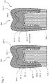
- FIG. 1 shows a schematic representation of a digital tooth model 200, which is placed on a remaining tooth 209.
- the external shape and the internal spatial structure of the subsequent dental restoration 100 are specified by the digital tooth model 200 .
- the outer shape can be generated in a CAD program.
- the outer shape is defined by the modeling of the dental restoration 100 in the CAD program.
- the internal spatial structure of the tooth model 200 can be calculated or taken from databases, for example derived from the structure of a natural tooth or from the external shape of the dental restoration 100 or one natural tooth can be calculated.
- an inner layer structure can thus be defined by the tooth model 200 and each individual layer 203-1, 203-2 and 203-3 can have its own restoration material 201-1, 201-2 and 201-3 be assigned to predetermined optical material parameters.
- the boundary surfaces 205-1 and 205-2 are located between the restoration materials 201-1, 201-2 and 201-3.
- the tooth model 200 reproduces, for example, a dental restoration 100 which is built up in layers from the three different restoration materials 201-1, 201-2 and 201-3.
- the restoration material 201-1 is used in an outer layer 203-1
- the restoration material 201-2 is used in a middle layer 203-2
- the restoration material 201-3 is used in an inner layer 203-3.
- the optical and physical properties of the respective assigned restoration materials 201-1, . . . 201-3 are known, such as color values, scattering values, reflection values, transmission values and/or absorption values.
- the later appearance of the dental restoration 100 can be calculated from this.
- the color and the translucency of the dental restoration 100 are calculated on the basis of the created tooth model 200 by means of a rendering (light simulation method) using ray tracing. In this way, the later appearance and the visual impression of the biomimetic from the tooth model 200 Dentures are precisely calculated, such as a crown, partial crown, inlay, onlay or a veneer.
- the rendering is performed using a physically correct simulation of the interaction of light with the restoration materials 201-1, ..., 201-3 used.
- existing natural tooth material can also be taken into account, such as a residual tooth 209 on which the dental restoration 100 is to be placed.
- the optical impression of the subsequent dental restoration 100 is therefore calculated for the specified internal structure and the selected restoration materials 201-1, . . . , 201-3.
- a computer-aided calculation of reflection, transmission and absorption values in the visible range can be carried out at at least three wavelengths.
- a target data set is first determined.
- the target data set can be obtained by optically detecting and evaluating an adjacent tooth.
- An electronic camera or a 3D scanner can be used for this, with which the color values, reflection, transmission and/or absorption values and the three-dimensional shape or an image of the natural tooth can be determined.
- a color measurement or translucency measurement can be carried out using a translucency scheme based on the eight natural color spaces. Based on this data, the dental restoration 100 is planned with properties that are as identical as possible.
- an initial tooth model 200 is created for the dental restoration 100, with which the outer shape and the inner spatial areas 203-1, ..., 203-3 of the tooth model 200 with the assigned restoration materials 201-1, 201-2 and 201 -3 to be specified. Based on this initial tooth model 200, the visual appearance of the dental restoration 100 is rendered to create an actual dataset that reflects the visual properties.
- the rendering of the dental restoration 100 is carried out from the same viewing angle or the same perspective from which the target data set based on the natural tooth was obtained. You can also render from different angles to improve the results.
- the rendering can take place for any viewing angle and any selectable environmental situation, such as a predefined lighting situation, taking into account neighboring teeth, a position of the dental restoration 100 in the oral cavity, or a shape and optical properties of the remaining tooth to be prepared. Other influencing conditions can also be taken into account during rendering, such as known optical data of a cement, composite and/or adhesive layer.
- a comparison (map matching) of the rendered actual image according to the actual data set with the recorded target image according to the target data set is then carried out and a deviation is determined, for example a mean deviation or minimum or maximum values.
- the deviation is a numerical one Value that quantifies the difference between the actual data set and the target data set.
- the spatial areas 203-1, . . . , 203-3 of the tooth model 200 can be changed. Both the boundary surfaces 205-1 and 205-2 and the subvolumes of the individual spatial regions 203-1, . . . , 203-3 can be changed here. In the case of large deviations, not only the spatial areas 203-1, . . . , 203-3 but also the restoration material 201-1, . By adapting the spatial areas 203-1, .
- the changed tooth model 200 is rendered again and a new comparison is made between the rendered actual data record and the recorded target data record in order to determine a new deviation.
- the steps of changing the tooth model and determining a deviation are then repeated until the deviation is below a predetermined value.
- nucleation areas for the formation of additional inner layers are defined.
- the seed surfaces can be arranged at any position within the volume of the tooth model 200, for example at an interface to the tooth substrate (preparation), on a labial surface of the dental restoration, in a central plane 213 tangential to the dental arch 211 or a rotationally symmetrical envelope of the vertical central axis of the tooth model 200
- the starting point is a homogeneous distribution of the restoration material, such as an artificial dentine material, in the spatial area of the entire dental restoration 100.
- the restoration material such as an artificial dentine material
- a second spatial area is formed, which extends into the interior of the dental restoration 100 is deformed and later forms the cutting layer.
- a restoration material with different optical and physical properties is assigned to this second spatial area.
- the second spatial region has interface 205-1 with the first spatial region.
- the seed layer may also extend from a surface of the tooth model 100 to grow a new layer of dentin material in a homogeneous area of enamel material.
- the germ layer can also be located spatially on a central plane 213 in the tooth model 200, for example tangentially to the dental arch 211 at the corresponding tooth position.
- a tooth model 200 with a specified external shape and internal architecture made up of several layers can also be specified.
- the interfaces 205 of the layers can be iteratively deformed three-dimensionally in order to to approach the overall optical appearance in a targeted manner to the optical target state.
- the target data set DS-S is obtained by an electronic camera 101, for example.
- the digitally generated tooth model 200 includes data on the spatial geometry of the dental restoration 100 and the associated restoration materials 201-1, ..., 201-3 from which the dental restoration 100 is to be produced and the spatial areas 203-1, 203- 2 and 203-3 in which the restorative materials 201-1, ..., 201-3 are arranged.
- the optical and physical properties of the restorative materials 201-1,..., 201-3 required for rendering are known in the rendering software. These can be taken from a parameter table, which is constantly being supplemented with new materials.
- the actual data record DS-I is obtained by subjecting the digital tooth model 200 to rendering with a selected material combination.
- rendering the spatial geometry of the dental restoration 100 and the optical and physical properties of the various restoration materials 201-1, . . . , 201-3 that occur are taken into account. It an adhesive material and a stump can also be taken into account.
- the propagation of light in the tooth model 200 can be described by Maxwell's equations.
- the rendering uses the Radiative Transport Equation (RTE) in which a propagation medium is described by the absorption coefficient, the scattering coefficient, the refractive index, and the scattering phase function.
- RTE Radiative Transport Equation
- the digital tooth model 200 includes the data on the spatial geometry of the dental restoration 100 and the internal architecture as well as the absorption coefficient, the scattering coefficient, the refractive index and the scattering phase function for the respective restoration materials 201-1, ..., 201-3.
- the scatter phase function can be solved numerically with any desired accuracy in a Monte Carlo simulation, in which a large number of photons propagate through the tooth model 200 on random paths.
- an actual data set DS-I for the appearance of the dental restoration 100 can be calculated by rendering, which takes into account the materials used, the external shape and the internal architecture of the tooth model 200 .
- This calculated actual data record DS-I can then be compared with the target data record DS-S, which was obtained on the basis of an adjacent tooth. To simplify the comparison, this can be done in a two-dimensional derivation (two-dimensional image). In general, however, three-dimensional methods can also be used.
- a numerical value is calculated as a measure of the deviation ⁇ E S,I between the actual data record DS-I and the target data record DS-S.
- the data record DS-S includes a representation of the tooth in a specified perspective.
- the dataset DS-I rendered from the tooth model 200 includes a representation of the tooth model 200 in the same perspective.
- the two images from the target data set DS-S and the actual data set DS-I are scaled to the same size and placed side by side.
- FIG. 5 shows a block diagram of a method for producing the dental restoration 100.
- the digital tooth model 200 is generated with the first spatial region 203-1, in which a first restoration material 201-1 is arranged, and the second spatial region 203-2 , in which a second restorative material 201-2 is arranged.
- This tooth model 200 serves as the starting point for the method.
- the initial digital tooth model 200 is rendered to generate the actual data set DS-I, which represents the optical properties of the digital tooth model 200.
- the tooth model 200 is calculated and simulated based on physical-optical material-specific parameters using a physically correct simulation tool.
- the discrepancy between the target data set DS-S and the actual data set DS-I is determined.
- step S104 the first spatial area 203-1 and/or the second spatial area 203-2 is changed by a smaller deviation ⁇ E S,I between the detected target data set DS-S and the actual data set DS-I of the new rendered digital tooth model 200 to obtain.
- step S103 of rendering the tooth model 200 with the deformed areas 203 and step S104 of calculating a deviation between the target data set DS-S and the actual data set DS-I are carried out again. If, for example, the deviation falls below a predetermined limit value, the inner shape of the tooth model 200 with the restoration materials 201-1, . . . , 201-3 is frozen.
- step S105 the dental restoration 100 is then produced on the basis of the ascertained digital tooth model 200 with the smaller deviation.
- the dental restoration 100 can be produced using a 3D printing method or another suitable method based on the tooth model 200 with the calculated spatial areas and the respective restoration materials 201-1, . . . , 201-3.
- a computer device can be used, which executes the calculation steps and then produces the dental restoration 100 by means of the production device.
- the computer device executes a computer program which comprises instructions which cause the computer device to carry out the required method steps.
- the computer device includes a processor and a digital memory in which the data sets and a computer program are stored, which executes the method steps and suitably controls a manufacturing device.
- the manufacturing device is, for example, a 3D printer that prints the dental restoration 100 with the different restoration materials. In general, however, other production devices that can produce the dental restoration with the different restoration materials can also be used.
- the optical appearance of the biomimetic tooth replacement is optimally approximated to the desired natural appearance.
- the method is an iterative, closed digital process in which modeling and simulation of the dental restoration 100 is as close as possible to the natural appearance in the approaches the patient's mouth. Because the spatial areas 203-1, 203-2 and 203-3 are simulated with the physical and optical parameters of known restoration materials 201-1, . . .
- the manufacturing method can achieve an optimal design of the inner multi-layer structure of the tooth model 200 and at the same time optimal aesthetics of the subsequent dental restoration 100 can be ensured. For this it is possible to find an optimal thickness and spatial position of the individual spatial regions 203-11, . . . 203-3.
- the restoration materials 201-1, . . . , 201-3 for producing the multi-layer dental restoration 100 for manufacturing the dental restoration 100 and their arrangement are known.
- the method is therefore an iterative process in which an optimized inner architecture of a dental restoration 100 is automatically generated. This can be achieved independently of a first structural specification for the tooth model 200. A reproducible optimal result with the available restoration materials 201-1, . . . Subjective influences of the user on the overall visual impression can be ruled out. Objective accuracy and repeatability of the method rule out errors caused by a user's spatial configuration.
- All method steps can be implemented by devices that are suitable for carrying out the respective method step. All functions performed by physical features can be a method step of a method.
Landscapes
- Health & Medical Sciences (AREA)
- Engineering & Computer Science (AREA)
- General Health & Medical Sciences (AREA)
- Public Health (AREA)
- Life Sciences & Earth Sciences (AREA)
- Epidemiology (AREA)
- Physics & Mathematics (AREA)
- Veterinary Medicine (AREA)
- Animal Behavior & Ethology (AREA)
- Oral & Maxillofacial Surgery (AREA)
- Dentistry (AREA)
- Theoretical Computer Science (AREA)
- General Physics & Mathematics (AREA)
- Manufacturing & Machinery (AREA)
- Chemical & Material Sciences (AREA)
- Materials Engineering (AREA)
- Medical Informatics (AREA)
- Computer Vision & Pattern Recognition (AREA)
- Geometry (AREA)
- Computer Graphics (AREA)
- Optics & Photonics (AREA)
- Radiology & Medical Imaging (AREA)
- Nuclear Medicine, Radiotherapy & Molecular Imaging (AREA)
- Biomedical Technology (AREA)
- Computer Hardware Design (AREA)
- General Engineering & Computer Science (AREA)
- Pathology (AREA)
- Primary Health Care (AREA)
- Biophysics (AREA)
- Evolutionary Computation (AREA)
- Quality & Reliability (AREA)
- Software Systems (AREA)
- Heart & Thoracic Surgery (AREA)
- Surgery (AREA)
- Mathematical Optimization (AREA)
- Mathematical Analysis (AREA)
- Computational Mathematics (AREA)
- Data Mining & Analysis (AREA)
- Molecular Biology (AREA)
- Databases & Information Systems (AREA)
Abstract
Description
- Die vorliegende Erfindung betrifft ein Verfahren zum Herstellen einer dentalen Restauration, eine Computervorrichtung zum Herstellen einer dentalen Restauration und ein Computerprogramm.
- Bei analogen und digitalen Fertigungsprozessen von dentalen Restaurationen erfolgt die Auswahl der Restaurationsmaterialen, wie deren Farbe, subjektiv durch einen Anwender unter Zuhilfenahme eines analogen Farbschlüssels. Danach folgt ein schichtweiser manueller Restaurationsaufbau. Ein Restaurationsaufbau erfolgt durch Übernahme eines Zahnaufbaus aus dem natürlichen Vorbild.
- Dieser kann in Datenbanken oder Bibliotheken bereitgestellt werden. Alternativ führt der Zahntechniker den Schichtaufbau basierend auf seiner Fachexpertise manuell oder CAD-gestützt aus. Diese Prozesse sind ungenau und geben das gewünschte natürliche Erscheinungsbild oft nur unzureichend wieder. Zudem bleibt es nur erfahrenen Zahntechnikern vorbehalten ein natürliches Erscheinungsbild zu erzielen.
- Es ist die technische Aufgabe der vorliegenden Erfindung, einen internen Aufbau für eine dentale Restauration derart zu bestimmen, dass diese einem gewünschten natürlichen Erscheinungsbild entspricht.
- Diese technische Aufgabe wird durch Gegenstände nach den unabhängigen Ansprüchen gelöst. Technisch vorteilhafte Ausführungsformen sind Gegenstand der abhängigen Ansprüche, der Beschreibung und der Zeichnungen.
- Gemäß einem ersten Aspekt wird die technische Aufgabe durch ein Verfahren zum Herstellen einer dentalen Restauration gelöst, mit den Schritten eines Erzeugens eines digitalen Zahnmodells mit einem ersten räumlichen Bereich, in dem ein erstes Restaurationsmaterial angeordnet ist, und einem zweiten räumlichen Bereich, in dem ein zweites Restaurationsmaterial angeordnet ist; eines Renderns des digitalen Zahnmodells zum Erzeugen eines Ist-Datensatzes, der die optischen Eigenschaften des digitalen Zahnmodells wiedergibt; eines Bestimmens einer Abweichung zwischen einem Soll-Datensatz und dem Ist-Datensatz; eines Verändern des ersten räumlichen Bereichs und/oder zweiten räumlichen Bereichs, um eine geringere Abweichung zwischen dem erfassten Soll-Datensatz und dem Ist-Datensatz des erneut gerenderten digitalen Zahnmodells zu erhalten; und eines Herstellens der dentalen Restauration auf Basis des digitalen Zahnmodells, mit der geringeren Abweichung. Der erste und der zweite räumliche Bereich bilden ein Subvolumen des Zahnmodells. Die Restaurationsmaterialien der räumlichen Bereiche können im Laufe des Verfahrens unverändert beibehalten werden.
- Durch das Verfahren kann die innere Architektur einer dentalen Restauration automatisch derart gestaltet werden, dass sich ein Gesamteindruck ergibt, der sich in das Zahngesamtbild des Patienten einfügt. Zudem können subjektive Einflüsse eines Anwenders auf den optischen Gesamteindruck der dentalen Restauration ausgeschlossen werden und eine hohe Genauigkeit und Wiederholbarkeit bei der Herstellung der dentalen Restauration erzielt werden.
- In einer technisch vorteilhaften Ausführungsform des Verfahrens erfolgt das Verändern derart, dass der erste räumliche Bereich ein äußerer Bereich des Zahnmodells ist, der nach Innen verformt wird. Von der Außenfläche kann ein zweiter räumlicher Bereich nach innen abgeleitet und verformt werden. Dabei wird eine neue Grenzfläche innerhalb des ersten räumlichen Bereichs erzeugt, die einen definierten Abstand zur Außenfläche hat. Dieser Abstand kann punktuell verändert werden. Dadurch wird beispielsweise der technische Vorteil erreicht, dass das Verfahren in einem weiten Raumbereich ausgeführt wird und gute Ergebnisse erhalten werden.
- In einer weiteren technisch vorteilhaften Ausführungsform des Verfahrens erfolgt das Verändern derart, dass der zweite räumliche Bereich ein innerer Bereich des Zahnmodells ist, der nach Außen verformt wird. Dadurch wird beispielsweise ebenfalls der technische Vorteil erreicht, dass das Verfahren in einem weiten Raumbereich ausgeführt wird und gute Ergebnisse erhalten werden.
- In einer weiteren technisch vorteilhaften Ausführungsform des Verfahrens wird das digitale Zahnmodells mit einer Grenzfläche zwischen dem ersten räumlichen Bereich und dem zweiten räumlichen Bereich erzeugt. Dadurch wird beispielsweise der technische Vorteil erreicht, dass die Grenzfläche verschoben werden kann, um gleichzeitig den ersten und den zweiten räumlichen Bereich zu verändern.
- In einer weiteren technisch vorteilhaften Ausführungsform des Verfahrens liegt die Grenzfläche in einer Mitte des digitalen Zahnmodells. Dadurch wird beispielsweise der technische Vorteil erreicht, dass das Verfahren schnell zu einer geringen Abweichung hin konvergiert.
- In einer weiteren technisch vorteilhaften Ausführungsform des Verfahrens verläuft die Grenzfläche tangential zum Zahnbogen an der entsprechenden Zahnposition. Dadurch wird beispielsweise der technische Vorteil erreicht, dass das Verfahren noch schneller zu einer zu einer geringen Abweichung hin konvergiert.
- In einer weiteren technisch vorteilhaften Ausführungsform des Verfahrens liegt die Grenzfläche an einer Innenseite oder einer Außenseite des digitalen Zahnmodells. Dadurch wird beispielsweise der technische Vorteil erreicht, dass das Zahnmodell von Innen oder außen her verändert werden kann.
- In einer weiteren technisch vorteilhaften Ausführungsform des Verfahrens wird durch die Grenzfläche ein Keimbereich gebildet, von dem ausgehend der erste räumliche Bereich und/oder der zweite räumliche Bereich verändert werden. Dadurch wird beispielsweise der technische Vorteil erreicht, dass ein Subvolumen gebildet wird, von dem aus sich die räumlichen Bereiche ausdehnen können.
- In einer weiteren technisch vorteilhaften Ausführungsform des Verfahrens sind der erste räumliche Bereich und der zweite räumliche Bereich schichtweise zueinander angeordnet. Dadurch wird beispielsweise der technische Vorteil erreicht, dass ein natürlicher Zahnaufbau nachgeahmt wird und sich mit wenigen Schritten eine geringe Abweichung erzielen lässt.
- In einer weiteren technisch vorteilhaften Ausführungsform des Verfahrens wird der erste räumliche Bereich und/oder zweite räumliche Bereich solange verändert, bis die Abweichung zwischen Soll- und Ist Datensatz unter einem vorgegebenen Wert liegt. Dadurch wird beispielsweise der technische Vorteil erreicht, dass die dentale Restauration mit einer vorbestimmten Genauigkeit hergestellt werden kann.
- In einer weiteren technisch vorteilhaften Ausführungsform des Verfahrens wird der erste räumliche Bereich und/oder zweite räumliche Bereich solange verändert, bis die Abweichung zwischen Soll- und Ist Datensatz ein Minimum erreicht hat. Dadurch wird beispielsweise der technische Vorteil erreicht, dass die dentale Restauration mit einer optimalen Anpassung an den Soll-Datensatz hergestellt werden kann.
- In einer weiteren technisch vorteilhaften Ausführungsform des Verfahrens wird der Soll-Datensatz auf Basis eines natürlichen Zahns erhalten. Dadurch wird beispielsweise der technische Vorteil erreicht, dass die dentale Restauration an einen natürlichen Zahn angepasst werden kann.
- In einer weiteren technisch vorteilhaften Ausführungsform des Verfahrens gibt der Soll-Datensatz die optischen Eigenschaften und/oder die Geometrie des natürlichen Zahns wieder. Dadurch wird beispielsweise der technische Vorteil erreicht, dass die Wiedergabetreue der dentalen Restauration nochmals verbessert wird.
- Gemäß einem zweiten Aspekt wird die technische Aufgabe durch eine Computervorrichtung zum Herstellen einer dentalen Restauration gelöst, mit einer Herstellungsvorrichtung, die geeignet ist, das Verfahren nach dem ersten Aspekt auszuführen. Dadurch werden die gleichen technischen Vorteile wie durch das Verfahren nach dem ersten Aspekt erreicht.
- Gemäß einem dritten Aspekt wird die technische Aufgabe durch ein Computerprogramm gelöst, umfassend Befehle, die bewirken, dass die Computervorrichtung nach dem zweiten Aspekt die Verfahrensschritte nach dem ersten Aspekt ausführt. Dadurch werden die gleichen technischen Vorteile wie durch das Verfahren nach dem ersten Aspekt erreicht. Ausführungsbeispiele der Erfindung sind in den Zeichnungen dargestellt und werden im Folgenden näher beschrieben.
-
- Fig. 1
- eine schematische Darstellung eines digitalen Zahnmodells;
- Fig. 2
- ein Verändern der räumlichen Bereiche eines Zahnmodells;
- Fig. 3
- eine Darstellung eines Vergleichs zwischen einem Soll-Datensatz und einem Ist-Datensatz;
- Fig. 4
- eine schematische Darstellung zur Berechnung einer Abweichung zwischen einem Soll-Datensatz und einem Ist Datensatz; und
- Fig. 5
- ein Blockdiagramm eines Verfahrens zum Herstellen einer dentalen Restauration.
-
Fig. 1 zeigt eine schematische Darstellung eines digitalen Zahnmodells 200, das auf einen Restzahn 209 aufgesetzt wird. Durch das digitale Zahnmodelle 200 wird die äußere Form und der innere räumliche Aufbau der späteren dentalen Restauration 100 vorgegeben. Die äußere Form kann hierzu in einem CAD-Programm erzeugt werden. Durch die Modellierung der dentalen Restauration 100 im CAD-Programm wird die äußere Form festgelegt. - Der innere räumliche Aufbau des Zahnmodells 200 kann errechnet oder aus Datenbanken entnommen werden, beispielsweise abgeleitet vom Aufbau eines natürlichen Zahns oder aus der äußeren Form der dentalen Restauration 100 oder eines natürlichen Zahns errechnet werden. Bei vorgegebener äußerer Form der dentalen Restauration 100 kann somit durch das Zahnmodell 200 ein innerer Schichtaufbau festgelegt werden und jeder einzelnen Schicht 203-1, 203-2, und 203-3 ein eigenes Restaurationsmaterial 201-1, 201-2 und 201-3 mit vorgegebenen optischen Materialparametern zugewiesen werden. Zwischen den Restaurationsmaterialien 201-1, 201-2, und 201-3 befinden sich die Grenzflächen 205-1 und 205-2. Die unterschiedlichen Restaurationsmaterialien 201-1, ..., 201-3 in den räumlichen Bereichen 203-1, ..., 203-3 sind durch die Grenzflächen 205-1 und 205-2 voneinander getrennt.
- Das Zahnmodell 200 gibt beispielsweise eine dentale Restauration 100 wieder, die schichtweise aus den drei unterschiedlichen Restaurationsmaterialen 201-1, 201-2 und 201-3 aufgebaut ist. In einer äußeren Schicht 203-1 wird das Restaurationsmaterial 201-1 verwendet, in einer mittleren Schicht 203-2 wird das Restaurationsmaterial 201-2 verwendet und in einer inneren Schicht 203-3 wird das Restaurationsmaterial 201-3 verwendet. Die optischen und physikalischen Eigenschaften der jeweils zugewiesenen Restaurationsmaterialien 201-1, ..., 201-3 sind bekannt, wie beispielsweise Farbwerte, Streuwerte, Reflexionswerte, Transmissionswerte und/oder Absorptionswerte.
- Sind die äußere Form und der innere Aufbau des Zahnmodells 200 mit den unterschiedlichen Restaurationsmaterialien 201-1, ..., 201-3 bekannt, kann hieraus das spätere Aussehen der dentalen Restauration 100 errechnet werden. Durch ein Rendering (Lichtsimulationsverfahren) mittels Strahlverfolgung (Ray Tracing) werden die Farbe und die Transluzenz der dentalen Restauration 100 auf Basis des erstellten Zahnmodells 200 berechnet. Auf diese Weise kann aus dem Zahnmodell 200 das spätere Aussehen und der optische Eindruck des biomimetischen Zahnersatzes präzise errechnet werden, wie beispielsweise einer Krone, Teilkrone, Inlay, Onlay oder einem Veneer.
- Das Rendern wird mittels einer physikalisch korrekten Simulation der Wechselwirkung von Licht mit den verwendeten Restaurationsmaterialien 201-1, ..., 201-3 durchgeführt. Dabei werden die bekannten optischen Parameter der einzelnen Restaurationsmaterialien 201-1, ..., 201-3 verwendet, um eine computergestützte Ansicht der dentalen Restauration 100 zu erzeugen.
- Hierzu kann zusätzlich bestehendes natürliches Zahnmaterial berücksichtigt werden, wie beispielsweise ein Restzahn 209, auf dem die dentale Restauration 100 aufgesetzt werden soll. Beim Rendern wird daher zu dem vorgegebenen inneren Aufbau und den ausgewählten Restaurationsmaterialien 201-1, ..., 201-3 der optische Eindruck der späteren dentalen Restauration 100 errechnet. Für das Rendern kann computergestützt eine Berechnung von Reflexions-, Transmissions- und Absorptionswerten im sichtbaren Bereich bei mindestens drei Wellenlängen durchgeführt werden.
- Für das Herstellungsverfahren der dentalen Restauration 100 wird zunächst ein Soll-Datensatz ermittelt. Der Soll-Datensatz kann durch ein optisches Erfassen und Auswerten eines benachbarten Zahns erhalten werden. Hierzu kann eine elektronische Kamera oder ein 3D-Scanner verwendet werden, mit dem die Farbwerte, Reflexions-, Transmissions- und/oder Absorptionswerte und die räumliche Form oder ein Bild des natürlichen Zahns bestimmt werden können. Daneben kann auch eine Farbmessung oder Transluzenz-Messung mit einem Transluzenz-Schema basierend auf den acht natürlichen Farbräumen durchgeführt werden. Auf Basis dieser Daten wird die dentale Restauration 100 mit möglichst identischen Eigenschaften geplant.
- Hierzu wird ein anfängliches Zahnmodell 200 für die dentale Restauration 100 erstellt, mit dem die äußere Form und die inneren räumlichen Bereiche 203-1, ..., 203-3 des Zahnmodells 200 mit den zugewiesenen Restaurationsmaterialien 201-1, 201-2 und 201-3 festgelegt werden. Auf Basis dieses anfänglichen Zahnmodells 200 wird das optische Erscheinungsbild der dentalen Restauration 100 gerendert, um einen Ist-Datensatz zu erzeugen, der die optischen Eigenschaften wiedergibt.
- Idealerweise wird das Rendern der dentalen Restauration 100 aus demselben Blickwinkel oder derselben Perspektive durchgeführt, aus der der Soll-Datensatz auf Basis des natürlichen Zahns gewonnen worden ist. Zur Verbesserung der Ergebnisse kann das Rendern auch aus verschiedenen Blickwinkeln erfolgen. Das Rendern kann für jeden beliebigen Blickwinkel und beliebig wählbare Umgebungssituationen erfolgen, wie beispielsweise einer vorgegebenen Beleuchtungssituation, unter Berücksichtigung von Nachbarzähnen, einer Position der dentalen Restauration 100 im Mundraum oder einer Form und optischen Eigenschaften des zu präparierenden Zahnrestes. Beim Rendern können auch weitere beeinflussende Bedingungen berücksichtigt werden, wie beispielsweise bekannte optische Daten einer Zement-, Komposit- und/oder Adhäsiv-Schicht.
- Anschließend wird ein Vergleich (Map Matching) des gerenderten Ist-Bildes gemäß dem Ist-Datensatz mit dem aufgenommenen Soll-Bild gemäß dem Soll-Datensatz durchgeführt und eine Abweichung ermittelt, beispielsweise eine mittlere Abweichung oder Minimal- oder Maximalwerte. Die Abweichung ist ein numerischer Wert, der die Unterschiedlichkeit des Ist-Datensatzes und des Soll-Datensatzes quantifiziert.
- Um das spätere Aussehen der dentalen Restauration 100 weiter anzupassen, können die räumlichen Bereiche 203-1, ..., 203-3 des Zahnmodells 200 verändert werden. Hierbei können sowohl die Grenzflächen 205-1 und 205-2 als auch die Subvolumina der einzelnen räumlichen Bereiche 203-1, ..., 203-3 verändert werden. Bei großen Abweichungen können nicht nur die räumlichen Bereiche 203-1, ..., 203-3 sondern zusätzlich auch das verwendete Restaurationsmaterial 201-1, ..., 201-3 angepasst werden. Durch die Anpassung der räumlichen Bereiche 203-1, ..., 203-3 kann beispielsweise eine Änderung der Topografie der Grenzfläche 205-1 zwischen Schneide und Dentin unter Beibehaltung der äußeren Form des Zahnmodells 200 erfolgen.
- Danach erfolgt ein erneutes Rendern des veränderten Zahnmodells 200 und ein erneuter Abgleich zwischen dem gerenderten Ist-Datensatz und dem aufgenommenen Soll-Datensatz, um eine neue Abweichung zu bestimmen. Die Schritte des Veränderns des Zahnmodells und des Bestimmens einer Abweichung werden dann solange wiederholt, bis die Abweichung unter einen vorgegebenen Wert liegt.
- Hierdurch erfolgt eine iterative Anpassung des Zahnmodells 200, indem die räumlichen Bereiche 203-1, ..., 203-3 angepasst werden. Die Anpassung der inneren Architektur des Zahnmodells 200 wird zur Optimierung des gesamtheitlichen optischen Erscheinungsbildes der dentalen Restauration 100 durchgeführt.
-
Fig. 2 zeigt ein Verändern der räumlichen Bereiche des Zahnmodells 200 im Rahmen des Herstellungsverfahrens. - In einem zunächst homogenen Volumen des Zahnmodells 200 werden Keimflächen für die Entstehung von zusätzlichen inneren Schichten definiert. Die Keimflächen können an beliebigen Positionen innerhalb des Volumens des Zahnmodells 200 angeordnet sein, beispielsweise an einer Grenzfläche zum Zahnsubstrat (Präparation), an einer labialen Oberfläche der dentalen Restauration, in einer Mittelebene 213 tangential zum Zahnbogen 211 oder einer rotationssymmetrischen Einhüllenden der senkrechten Mittelachse des Zahnmodells 200.
- Ausgangspunkt ist eine homogene Verteilung des Restaurationsmaterials, wie beispielsweise ein künstliches Dentinmaterial, im räumlichen Bereich der gesamten dentalen Restauration 100. Ausgehend von einer labialen Oberfläche (Schneide) des ersten räumlichen Bereichs wird ein zweiter räumlicher Bereich gebildet, der in das Innere der dentalen Restauration 100 verformt wird und später die Schneidenschicht bildet. Diesem zweiten räumlichen Bereich ist ein Restaurationsmaterial mit anderen optischen und physikalischen Eigenschaften zugeordnet. Der zweite räumliche Bereich weist Grenzfläche 205-1 zu dem ersten räumlichen Bereich auf.
- Die Keimschicht kann auch von einer Oberfläche des Zahnmodells 100 ausgehen, um in einem homogenen Bereich aus Schmelzmaterial eine neue Schicht aus Dentinmaterial wachsen zu lassen. Die Keimschicht kann sich im Zahnmodell 200 auch räumlich auf einer Mittelebene 213 befinden, beispielsweise tangential zum Zahnbogen 211 an der entsprechenden Zahnposition.
- Es kann auch ein Zahnmodell 200 mit vorgegebener äußerer Form und innerer Architektur aus mehreren Schichten vorgegeben sein. In diesem Fall können die Grenzflächen 205 der Schichten iterativ dreidimensional verformt werden, um das gesamtheitliche optische Erscheinungsbild gezielt dem optischen Soll-Zustand anzunähern.
- Ausgehend von einer neu entstandenen Grenzfläche 205 können weitere zusätzliche Schichten nach demselben Verfahren hinzugefügt werden. Die Verformung der jeweiligen Grenzflächen 205 erfolgt dabei durch einen iterativen Abgleich des Soll-Datensatzes und des Ist-Datensatzes solange, bis ein vorgegebener Grenzwert erreicht wird.
-
Fig. 3 zeigt eine schematische Darstellung einer Abweichung ΔES,I zwischen dem Soll-Datensatz DS-S und dem Ist-Datensatz DS-I. Der Soll-Datensatz DS-S wird beispielsweise durch eine elektronische Kamera 101 erhalten. - Das digital erzeugte Zahnmodell 200 umfasst Daten über die räumliche Geometrie der dentalen Restauration 100 und die zugeordneten Restaurationsmaterialien 201-1, ..., 201-3, aus denen die dentale Restauration 100 hergestellt werden soll und die räumlichen Bereiche 203-1, 203-2 und 203-3, in denen die Restaurationsmaterialien 201-1, ..., 201-3 angeordnet sind. Die optischen und physikalischen Eigenschaften der Restaurationsmaterialien 201-1, ..., 201-3, die für das Rendern erforderlich sind, sind in der Rendering-Software bekannt. Diese können aus einer Parametertabelle entnommen werden, die ständig um neue Materialien ergänzt wird.
- Der Ist-Datensatz DS-I wird erhalten, indem das digitale Zahnmodell 200 mit einer ausgewählten Materialkombination dem Rendering unterzogen wird. Beim Rendering werden die räumliche Geometrie der dentalen Restauration 100 und die optischen und physikalischen Eigenschaften der verschiedenen, vorkommenden Restaurationsmaterialien 201-1, ..., 201-3 berücksichtigt. Es kann zusätzlich ein Klebematerial und ein Stumpf berücksichtigt werden.
- Die Ausbreitung von Licht in dem Zahnmodell 200 kann durch die Maxwell-Gleichungen beschrieben werden. Das Rendering verwendet beispielsweise die Strahlungstransportgleichung (RTE - Radiative Transport Equation), bei der ein Ausbreitungsmedium durch den Absorptionskoeffizienten, den Streukoeffizienten, den Brechungsindex und die Streuphasenfunktion beschrieben wird.
- Das digitale Zahnmodell 200 umfasst die Daten über die räumliche Geometrie der dentalen Restauration 100 und die innere Architektur sowie den Absorptionskoeffizienten, den Streukoeffizienten, den Brechungsindex und die Streuphasenfunktion für die jeweiligen Restaurationsmaterialien 201-1, ..., 201-3. Die Streuphasenfunktion kann beim Rendern auf Basis des Zahnmodells 200 mit den genannten Parametern in einer Monte-Carlo-Simulation in jeder gewünschten Genauigkeit numerisch gelöst werden, bei der eine Vielzahl von Photonen auf zufälligen Pfaden durch das Zahnmodell 200 propagieren.
- Daraus lässt sich durch das Rendern ein Ist-Datensatz DS-I für das Aussehen der dentalen Restauration 100 errechnen, der die verwendeten Materialien, die äußere Form und die innere Architektur des Zahnmodells 200 berücksichtigt. Dieser berechnete Ist-Datensatz DS-I kann anschließend mit dem Soll-Datensatz DS-S, der auf Basis eines Nachbarzahns gewonnen worden ist, verglichen werden. Zur Vereinfachung des Vergleichs kann dieser in einer zweidimensionalen Ableitung (zweidimensionales Bild) erfolgen. Im Allgemeinen können jedoch auch dreidimensionale Verfahren verwendet werden. Als Maß für die Abweichung ΔES,I zwischen dem Ist-Datensatz DS-I und dem Soll-Datensatz DS-S wird ein numerischer Wert berechnet.
-
Fig. 4 zeigt eine schematische Darstellung zur Berechnung einer Abweichung ΔES,I zwischen dem Soll-Datensatz DS-S und einem Ist-Datensatz DS-I. Beispielsweise umfasst der Datensatz DS-S eine Darstellung des Zahns in einer vorgegebenen Perspektive. Demgegenüber umfasst der Datensatz DS-I, der aus dem Zahnmodell 200 gerendert worden ist, eine Darstellung des Zahnmodells 200 in der gleichen Perspektive. Die beiden Abbildungen aus dem Soll-Datensatz DS-S und dem Ist-Datensatz DS-I werden auf die gleiche Größe skaliert und nebeneinandergesetzt. - Die euklidische Abweichung ΔES,I zwischen dem Soll-Datensatz DS-S und dem Ist-Datensatz DS-I kann berechnet werden, indem die Unterschiede in den Farbwerten der Pixel entlang der Vergleichslinien 207 aufsummiert werden, beispielsweise im L*a*b*-Farbraum. Diese Vergleichslinien 207 können beliebig verschoben werden, indem beispielsweise die Zahnhälften zusammengeschoben werden. Im Allgemeinen kann die Vergleichslinie 207 jedoch auch einen anderen Verlauf aufweisen. Der Vergleich kann auf Pixel-Ebene als kleinste Auflösung erfolgen.

- Je größer der Unterschied im Farbverlauf entlang der Vergleichslinie 207 ist, desto größer ist die numerische Abweichung ΔES,I. Bei vollkommener farblicher Übereinstimmung zwischen dem Soll-Datensatz DS-S und dem Ist-Datensatz DS-I ist die Abweichung ΔES,I Null. Im Allgemeinen können jedoch auch andere Verfahren zum Berechnen der Abweichung ΔES,I herangezogen werden, wie beispielsweise auf der Basis von Spektralinformation.
-
Fig. 5 zeigt ein Blockdiagramm eines Verfahrens zum Herstellen der dentalen Restauration 100. Zunächst wird in Schritt S101 das digitale Zahnmodell 200 mit dem ersten räumlichen Bereich 203-1, in dem ein erstes Restaurationsmaterial 201-1 angeordnet ist, und dem zweiten räumlichen Bereich 203-2 erzeugt, in dem in zweites Restaurationsmaterial 201-2 angeordnet ist. Dieses Zahnmodell 200 dient als Startpunkt für das Verfahren. In Schritt S102 wird das anfängliche digitale Zahnmodell 200 zum Erzeugen des Ist-Datensatzes DS-I gerendert, der die optischen Eigenschaften des digitalen Zahnmodells 200 wiedergibt. Die Berechnung und Simulation des Zahnmodells 200 erfolgt basierend auf physikalisch-optisch materialspezifischen Kennwerten mittels eines physikalisch korrekten Simulationstools. In Schritt S103 wird die Abweichung zwischen dem Soll-Datensatz DS-S und dem Ist-Datensatz DS-I bestimmt. - In Schritt S104 wird der erste räumliche Bereich 203-1 und/oder der zweite räumliche Bereichs 203-2 verändert, um eine geringere Abweichung ΔES,I zwischen dem erfassten Soll-Datensatz DS-S und dem Ist-Datensatz DS-I des erneut gerenderten digitalen Zahnmodells 200 zu erhalten. Zu diesem Zweck werden der Schritt S103 des Renderns des Zahnmodells 200 mit den verformten Bereichen 203 und der Schritt S104 des Berechnens einer Abweichung zwischen dem Soll-Datensatz DS-S und dem Ist-Datensatz DS-I erneut durchgeführt. Ist beispielsweise ein vorgegebener Grenzwert für die Abweichung unterschritten, wird die innere Formgebung des Zahnmodells 200 mit den Restaurationsmaterialien 201-1, ..., 201-3 eingefroren. In Schritt S105 wird dann die dentale Restauration 100 auf Basis des ermittelten digitalen Zahnmodells 200 mit der geringeren Abweichung hergestellt. Die dentale Restauration 100 kann durch ein 3D-Druckverfahren oder ein anderes geeignetes Verfahren auf Basis des Zahnmodells 200 mit den berechneten räumlichen Bereichen und den jeweiligen Restaurationsmaterialien 201-1, ..., 201-3 hergestellt werden.
- In diesem Fall kann eine Computervorrichtung verwendet werden, die die Berechnungsschritte ausführt und anschließend die dentale Restauration 100 mittels der Herstellungsvorrichtung herstellt. Die Computervorrichtung führt zu diesem Zweck ein Computerprogramm aus, das Befehle umfasst, die bewirken, dass die Computervorrichtung die erforderlichen Verfahrensschritte ausführt. Die Computervorrichtung umfasst einen Prozessor und einen digitalen Speicher, in dem die Datensätze und ein Computerprogramm gespeichert ist, das die Verfahrensschritte ausführt und eine Herstellungsvorrichtung geeignet ansteuert. Die Herstellungsvorrichtung ist beispielsweise ein 3D-Drucker, der die dentale Restauration 100 mit den unterschiedlichen Restaurationsmaterialien druckt. Im Allgemeinen können jedoch auch andere Herstellungsvorrichtungen verwendet werden, die die dentale Restauration mit den unterschiedlichen Restaurationsmaterialien herstellen kann.
- Nach einem Einsetzen der so erzeugten dentalen Restauration 100 ist das optische Erscheinungsbild des biomimetischen Zahnersatzes optimal an das gewünschte natürliche Erscheinungsbild angenähert.
- Bei dem Verfahren handelt es sich um einen iterativen, geschlossenen digitalen Prozess, bei dem sich eine Modellierung und Simulation der dentalen Restauration 100 soweit wie möglich an das natürliche Erscheinungsbild im Patientenmund annähert. Weil mit den physikalischen und optischen Parametern bekannter Restaurationsmaterialien 201-1, ..., 201-3 in den räumlichen Bereichen 203-1, 203-2 und 203-3 simuliert wird, kann ein rechnergestütztes naturgetreues Erscheinungsbild der dentalen Restauration 100 gewonnen werden.
- Durch das Herstellungsverfahren kann eine optimale Gestaltung des inneren mehrschichtigen Aufbaus des Zahnmodels 200 erreicht werden und gleichzeitig eine optimale Ästhetik der späteren dentalen Restauration 100 sichergestellt werden. Hierzu ist es möglich, eine optimale Dicke und räumliche Lage der einzelnen räumlichen Bereiche 203-11, ..., 203-3 zu finden. Die Restaurationsmaterialien 201-1, ..., 201-3 zur Erzeugung der mehrschichtigen dentalen Restauration 100 für die Fertigung der dentalen Restauration 100 und deren Anordnung sind bekannt.
- Bei dem Verfahren handelt es sich somit um einen iterativen Prozess, bei dem automatisch eine optimierte innere Architektur einer dentalen Restauration 100 erzeugt wird. Dies kann unabhängig von einer ersten strukturellen Vorgabe für das Zahnmodell 200 erreicht werden. Durch die Übereinstimmung zwischen dem Ist-Datensatz und dem Soll-Datensatz (Best Match) wird ein wiederholbares optimales Ergebnis mit den zur Verfügung stehenden Restaurationsmaterialien 201-1, ..., 201-3 und eine optimale Ästhetik der dentalen Restauration 100 erreicht. Subjektive Einflüsse des Anwenders auf den optischen Gesamteindruck können hierbei ausgeschlossen werden. Eine objektive Genauigkeit und Wiederholbarkeit des Verfahrens schließen Fehler durch eine räumliche Gestaltung eines Benutzers aus.
- Alle in Verbindung mit einzelnen Ausführungsformen der Erfindung erläuterten und gezeigten Merkmale können in unterschiedlicher Kombination in dem erfindungsgemäßen Gegenstand vorgesehen sein, um gleichzeitig deren vorteilhafte Wirkungen zu realisieren.
- Alle Verfahrensschritte können durch Vorrichtungen implementiert werden, die zum Ausführen des jeweiligen Verfahrensschrittes geeignet sind. Alle Funktionen, die von gegenständlichen Merkmalen ausgeführt werden, können ein Verfahrensschritt eines Verfahrens sein.
- Der Schutzbereich der vorliegenden Erfindung ist durch die Ansprüche gegeben und wird durch die in der Beschreibung erläuterten oder den Figuren gezeigten Merkmale nicht beschränkt.
-
- 100
- Dentale Restauration
- 101
- elektronische Kamera
- 200
- Zahnmodell
- 201
- Restaurationsmaterial
- 203
- räumlicher Bereich/Schicht
- 205
- Grenzfläche
- 207
- Vergleichslinie
- 209
- Zahnstumpf
- 211
- Zahnbogen
- 213
- Mittelebene
- DS-I
- Ist-Datensatz
- DS-S
- Soll Datensatz
Claims (15)
- Verfahren zum Herstellen einer dentalen Restauration (100), mit den Schritten:- Erzeugen (S101) eines digitalen Zahnmodells (200) mit einem ersten räumlichen Bereich (203-1), in dem ein erstes Restaurationsmaterial (201-1) angeordnet ist, und einem zweiten räumlichen Bereich (203-2), in dem ein zweites Restaurationsmaterial (201-2) angeordnet ist;- Rendern (S102) des digitalen Zahnmodells (200) zum Erzeugen eines Ist-Datensatzes (DS-I), der die optischen Eigenschaften des digitalen Zahnmodells (200) wiedergibt;- Bestimmen (S103) einer Abweichung (ΔES,I) zwischen einem Soll-Datensatz (DS-S) und dem Ist-Datensatz (DS-I);- Verändern (S104) des ersten räumlichen Bereichs (203-1) und/oder zweiten räumlichen Bereichs (203-2), um eine geringere Abweichung (ΔES,I) zwischen dem erfassten Soll-Datensatz (DS-S) und dem Ist-Datensatz (DS-I) des erneut gerenderten digitalen Zahnmodells (200) zu erhalten; und- Herstellen (S105) der dentalen Restauration (100) auf Basis des digitalen Zahnmodells (200) mit der geringeren Abweichung.
- Verfahren nach Anspruch 1, wobei das Verändern (S104) derart erfolgt, dass der erste räumlichen Bereich ein äußerer Bereich des Zahnmodells (200) ist, der nach Innen verformt wird.
- Verfahren nach einem der vorangehenden Ansprüche, wobei das Verändern (S104) derart erfolgt, dass der zweite räumliche Bereich ein innerer Bereich des Zahnmodells (200) ist, der nach Außen verformt wird.
- Verfahren nach einem der vorangehenden Ansprüche, wobei das digitale Zahnmodells (200) mit einer Grenzfläche zwischen dem ersten räumlichen Bereich (203-1) und dem zweiten räumlichen Bereich (203-2) erzeugt wird.
- Verfahren nach Anspruch 4, wobei die Grenzfläche in einer Mitte des digitalen Zahnmodells (200) liegt.
- Verfahren nach Anspruch 5, wobei die Grenzfläche (205) tangential zum Zahnbogen (211) an der entsprechenden Zahnposition verläuft.
- Verfahren Anspruch 4, wobei die Grenzfläche an einer Innenseite oder einer Außenseite des digitalen Zahnmodells (200) liegt.
- Verfahren nach Anspruch 7, wobei durch die Grenzfläche (205) ein Keimbereich gebildet wird, von dem ausgehend der erste räumliche Bereich (203-1) und/oder der zweite räumliche Bereich (203-2) verändert werden.
- Verfahren nach einem der vorangehenden Ansprüche, wobei der erste räumliche Bereich (203-1) und der zweite räumliche Bereich (203-2) schichtweise zueinander angeordnet sind.
- Verfahren nach einem der vorangehenden Ansprüche, wobei der erste räumliche Bereich (203-1) und/oder zweite räumliche Bereich (203-2) solange verändert wird, bis die Abweichung unter einem vorgegebenen Wert liegt.
- Verfahren nach einem der vorangehenden Ansprüche, wobei der erste räumliche Bereich (203-1) und/oder zweite räumliche Bereich (203-2) solange verändert wird, bis die Abweichung ein Minimum erreicht hat.
- Verfahren nach einem der vorangehenden Ansprüche, wobei der Soll-Datensatz (DS-S) auf Basis eines natürlichen Zahns erhalten wird.
- Verfahren nach Anspruch 12, wobei der Soll-Datensatz (DS-S) die optischen Eigenschaften und/oder die Geometrie des natürlichen Zahns wiedergibt.
- Computervorrichtung zum Herstellen einer dentalen Restauration (100), mit einer Herstellungsvorrichtung, die geeignet ist, das Verfahren nach einem der Ansprüche 1 bis 13 auszuführen.
- Computerprogramm, umfassend Befehle, die bewirken, dass die Computervorrichtung des Anspruchs 14 die Verfahrensschritte nach einem der Ansprüche 1 bis 13 ausführt.
Priority Applications (7)
| Application Number | Priority Date | Filing Date | Title |
|---|---|---|---|
| US17/475,378 US20220110725A1 (en) | 2020-10-13 | 2021-09-15 | Method For Designing A Dental Restoration |
| US17/475,402 US12045984B2 (en) | 2020-10-13 | 2021-09-15 | Comparison of color images of three-dimensional dental structures |
| US17/475,399 US11790529B2 (en) | 2020-10-13 | 2021-09-15 | Method for fabricating a dental restoration |
| US17/475,395 US20220110726A1 (en) | 2020-10-13 | 2021-09-15 | Method For Producing A Dental Restoration |
| KR1020210132828A KR20220048944A (ko) | 2020-10-13 | 2021-10-07 | 치과용 복원물을 생산하기 위한 방법 |
| CN202111178923.2A CN114404085B (zh) | 2020-10-13 | 2021-10-09 | 制造牙齿修复体的方法 |
| JP2021166572A JP7628928B2 (ja) | 2020-10-13 | 2021-10-11 | 歯科補綴物を製造する方法 |
Applications Claiming Priority (1)
| Application Number | Priority Date | Filing Date | Title |
|---|---|---|---|
| EP20201553.3A EP3984495B1 (de) | 2020-10-13 | 2020-10-13 | Verfahren zum gestalten einer dentalen restauration |
Publications (2)
| Publication Number | Publication Date |
|---|---|
| EP3984494A1 true EP3984494A1 (de) | 2022-04-20 |
| EP3984494B1 EP3984494B1 (de) | 2025-01-29 |
Family
ID=72852472
Family Applications (4)
| Application Number | Title | Priority Date | Filing Date |
|---|---|---|---|
| EP20201553.3A Active EP3984495B1 (de) | 2020-10-13 | 2020-10-13 | Verfahren zum gestalten einer dentalen restauration |
| EP20215936.4A Active EP3984492B1 (de) | 2020-10-13 | 2020-12-21 | Vergleich von farbbildern dreidimensionaler dentaler strukturen |
| EP20215945.5A Active EP3984494B1 (de) | 2020-10-13 | 2020-12-21 | Verfahren zum herstellen einer dentalen restauration |
| EP20215943.0A Active EP3984493B1 (de) | 2020-10-13 | 2020-12-21 | Verfahren zum herstellen einer dentalen restauration |
Family Applications Before (2)
| Application Number | Title | Priority Date | Filing Date |
|---|---|---|---|
| EP20201553.3A Active EP3984495B1 (de) | 2020-10-13 | 2020-10-13 | Verfahren zum gestalten einer dentalen restauration |
| EP20215936.4A Active EP3984492B1 (de) | 2020-10-13 | 2020-12-21 | Vergleich von farbbildern dreidimensionaler dentaler strukturen |
Family Applications After (1)
| Application Number | Title | Priority Date | Filing Date |
|---|---|---|---|
| EP20215943.0A Active EP3984493B1 (de) | 2020-10-13 | 2020-12-21 | Verfahren zum herstellen einer dentalen restauration |
Country Status (6)
| Country | Link |
|---|---|
| US (4) | US12045984B2 (de) |
| EP (4) | EP3984495B1 (de) |
| JP (4) | JP7813534B2 (de) |
| KR (4) | KR20220048944A (de) |
| CN (4) | CN114419242B (de) |
| ES (4) | ES2992508T3 (de) |
Families Citing this family (11)
| Publication number | Priority date | Publication date | Assignee | Title |
|---|---|---|---|---|
| ES2992508T3 (es) * | 2020-10-13 | 2024-12-13 | Ivoclar Vivadent Ag | Procedimiento para configurar una restauración dental |
| US12651431B2 (en) * | 2021-03-24 | 2026-06-09 | Medit Corp. | Data processing device and data processing method |
| WO2022271807A1 (en) * | 2021-06-22 | 2022-12-29 | Digital Dental Technologies Llc | Systems and methods for providing oral devices using at-home dental impression kits |
| JP7698604B2 (ja) * | 2022-04-08 | 2025-06-25 | 株式会社三共 | 遊技機 |
| JP7698602B2 (ja) * | 2022-04-08 | 2025-06-25 | 株式会社三共 | 遊技機 |
| JP7698601B2 (ja) * | 2022-04-08 | 2025-06-25 | 株式会社三共 | 遊技機 |
| JP7698603B2 (ja) * | 2022-04-08 | 2025-06-25 | 株式会社三共 | 遊技機 |
| JP7653160B2 (ja) * | 2022-11-30 | 2025-03-28 | 順一 上田 | 色調採得支援方法 |
| DE102023115125A1 (de) * | 2023-06-09 | 2024-12-12 | Kurt-Jürgen Erdelt | Verfahren zum Herstellen von herausnehmbarem Zahnersatz und nach dem Verfahren hergestellter herausnehmbarer Zahnersatz |
| CN118096725B (zh) * | 2024-04-18 | 2024-07-09 | 武汉市双桥科技有限公司 | 基于图像处理预防模具事故的检测方法 |
| US12572131B1 (en) | 2025-06-27 | 2026-03-10 | Ut-Battelle, Llc | Flexibilities used in slicer to ensure level printing for additive system |
Citations (1)
| Publication number | Priority date | Publication date | Assignee | Title |
|---|---|---|---|---|
| WO2019023461A1 (en) * | 2017-07-27 | 2019-01-31 | Align Technology, Inc. | TINT, TRANSPARENCY AND DENTAL ENAMEL |
Family Cites Families (66)
| Publication number | Priority date | Publication date | Assignee | Title |
|---|---|---|---|---|
| US4654794A (en) * | 1984-02-18 | 1987-03-31 | Colorgen, Inc. | Methods for determining the proper coloring for a tooth replica |
| US6254385B1 (en) * | 1997-01-02 | 2001-07-03 | Lj Laboratories, Llc | Apparatus and method for measuring optical characteristics of teeth |
| DE19922870A1 (de) * | 1999-05-19 | 2000-12-07 | Paul Weigl | Verfahren zur automatischen, individuell angepaßten Farb-, Transluzenz-, Helligkeits- und Fluoreszenzgebung von zahntechnischen Restaurationen |
| US7234937B2 (en) * | 1999-11-30 | 2007-06-26 | Orametrix, Inc. | Unified workstation for virtual craniofacial diagnosis, treatment planning and therapeutics |
| US7077647B2 (en) * | 2002-08-22 | 2006-07-18 | Align Technology, Inc. | Systems and methods for treatment analysis by teeth matching |
| DE112004001035B4 (de) * | 2003-06-11 | 2014-09-11 | Toei Electric Co., Ltd. | Vorrichtung zur Positionsermittlung einer Zahnwurzelspitze |
| US20050170315A1 (en) * | 2004-01-20 | 2005-08-04 | Strobel Wolfgang M. | System, method, computer program product and apparatus for producing dental restorations |
| US20080306724A1 (en) * | 2007-06-08 | 2008-12-11 | Align Technology, Inc. | Treatment planning and progress tracking systems and methods |
| US8591225B2 (en) * | 2008-12-12 | 2013-11-26 | Align Technology, Inc. | Tooth movement measurement by automatic impression matching |
| US8562338B2 (en) * | 2007-06-08 | 2013-10-22 | Align Technology, Inc. | Treatment progress tracking and recalibration |
| US10342638B2 (en) * | 2007-06-08 | 2019-07-09 | Align Technology, Inc. | Treatment planning and progress tracking systems and methods |
| US8075306B2 (en) * | 2007-06-08 | 2011-12-13 | Align Technology, Inc. | System and method for detecting deviations during the course of an orthodontic treatment to gradually reposition teeth |
| EP2240115B1 (de) * | 2007-12-21 | 2019-05-29 | 3M Innovative Properties Company | Auf verkleinerten bildern basierende überwachung kieferorthopädischer behandlungen |
| DK2269533T3 (da) | 2008-03-21 | 2021-07-26 | Atsushi Takahashi | Tredimensionelt digitalt forstørrelsesapparat-operationsunderstøttende system |
| JP5173578B2 (ja) * | 2008-05-15 | 2013-04-03 | キヤノン株式会社 | 画像処理方法及び印刷装置とその制御方法 |
| EP2259034A1 (de) * | 2009-05-29 | 2010-12-08 | Ivoclar Vivadent AG | Dentalfarben-Analysevorrichtung |
| JP6363341B2 (ja) * | 2010-07-12 | 2018-07-25 | 3シェイプ アー/エス | テクスチャ的特徴を用いる物体の3dモデル化方法 |
| EP2486892B1 (de) | 2011-02-14 | 2015-09-02 | Ivoclar Vivadent AG | Verfahren zur Herstellung eines dentalen Restaurationsteils sowie CAD/CAM-Vorrichtung |
| KR102005004B1 (ko) * | 2011-12-22 | 2019-07-29 | 쓰리엠 이노베이티브 프로퍼티즈 컴파니 | 치아 수복물을 제조하기 위한 방법 및 시스템 |
| DE102013204146A1 (de) * | 2013-03-11 | 2014-09-25 | Eos Gmbh Electro Optical Systems | Verfahren zur verzugsfreien Herstellung von Objekten mittels eines generativen Schichtbauverfahrens und solchermaßen hergestelltes Dentalmodell |
| CA2902771C (en) * | 2013-03-15 | 2018-08-14 | Synaptive Medical (Barbados) Inc. | Context aware surgical systems |
| WO2015101961A1 (en) * | 2014-01-06 | 2015-07-09 | Koninklijke Philips N.V. | Articulated structure registration in magnetic resonance images of the brain |
| US10010387B2 (en) * | 2014-02-07 | 2018-07-03 | 3Shape A/S | Detecting tooth shade |
| US9510757B2 (en) * | 2014-05-07 | 2016-12-06 | Align Technology, Inc. | Identification of areas of interest during intraoral scans |
| FR3027508B1 (fr) * | 2014-10-27 | 2016-12-23 | H 42 | Procede de controle de la dentition |
| US11147652B2 (en) * | 2014-11-13 | 2021-10-19 | Align Technology, Inc. | Method for tracking, predicting, and proactively correcting malocclusion and related issues |
| US9770217B2 (en) * | 2015-01-30 | 2017-09-26 | Dental Imaging Technologies Corporation | Dental variation tracking and prediction |
| CN105167874B (zh) | 2015-07-23 | 2017-07-21 | 范翌 | 基于数字照片和hsb色彩系统的口腔数字化比色方法 |
| US11583365B2 (en) * | 2015-10-07 | 2023-02-21 | uLab Systems, Inc. | System and methods for tooth movement as a flock |
| EP3442463B1 (de) | 2016-04-12 | 2022-11-09 | Nobel Biocare Services AG | Cad/cam implementierte verfahren zur herstellung eines zahnersatzes |
| FR3050375A1 (fr) * | 2016-04-22 | 2017-10-27 | H43 Dev | Procede de controle de la dentition |
| US10387746B2 (en) * | 2016-05-06 | 2019-08-20 | Ohio State Innovation Foundation | Image color data normalization and color matching system for translucent material |
| US20190231493A1 (en) | 2016-06-20 | 2019-08-01 | Carestream Dental Technology Topco Limited | Dental restoration assessment using virtual model |
| CN210727927U (zh) * | 2016-07-27 | 2020-06-12 | 阿莱恩技术有限公司 | 口内扫描系统 |
| US10507087B2 (en) * | 2016-07-27 | 2019-12-17 | Align Technology, Inc. | Methods and apparatuses for forming a three-dimensional volumetric model of a subject's teeth |
| US10709733B2 (en) * | 2016-08-11 | 2020-07-14 | Regents Of The University Of Minnesota | Nonsurgical techniques for restoring tooth enamel |
| US10792127B2 (en) * | 2017-01-24 | 2020-10-06 | Align Technology, Inc. | Adaptive orthodontic treatment |
| US10499793B2 (en) * | 2017-02-17 | 2019-12-10 | Align Technology, Inc. | Longitudinal analysis and visualization under limited accuracy system |
| EP3453356B1 (de) * | 2017-06-08 | 2022-05-04 | Korea Institute of Machinery & Materials | System zur herstellung eines kieferorthopädischen drahts und verfahren zur herstellung des kieferorthopädischen drahts |
| CN107564090A (zh) * | 2017-09-07 | 2018-01-09 | 杭州美齐科技有限公司 | 一种三维牙颌模型渲染方法 |
| EP3459438B1 (de) * | 2017-09-26 | 2020-12-09 | The Procter & Gamble Company | Vorrichtung und verfahren zur bestimmung von zahnbelag |
| CN119235481A (zh) * | 2017-11-01 | 2025-01-03 | 阿莱恩技术有限公司 | 自动治疗规划 |
| ES2918623T3 (es) * | 2018-01-30 | 2022-07-19 | Dental Monitoring | Sistema de mejora de un modelo dental digital |
| EP3530232B1 (de) * | 2018-02-21 | 2021-04-28 | Ivoclar Vivadent AG | Verfahren zur ausrichtung eines dreidimensionalen modells eines gebisses eines patienten auf ein bild des gesichtes des patienten, das mit einer kamera aufgenommen wurde |
| US11120179B2 (en) * | 2018-03-22 | 2021-09-14 | James R. Glidewell Dental Ceramics, Inc. | System and method for performing quality control |
| US11210788B2 (en) * | 2018-03-22 | 2021-12-28 | James R. Glidewell Dental Ceramics, Inc. | System and method for performing quality control |
| US11334977B2 (en) * | 2018-03-22 | 2022-05-17 | James R. Glidewell Dental Ceramics, Inc. | System and method for performing quality control of manufactured models |
| ES2963115T3 (es) * | 2018-05-03 | 2024-03-25 | Dentsply Sirona Inc | Métodos de impresión tridimensional para fabricar un aparato dental |
| EP4331532B1 (de) * | 2018-06-29 | 2025-08-27 | Align Technology, Inc. | Bereitstellung eines simulierten ergebnisses einer zahnbehandlung an einem patienten |
| US20210259808A1 (en) * | 2018-07-31 | 2021-08-26 | 3M Innovative Properties Company | Method for automated generation of orthodontic treatment final setups |
| EP3659549B1 (de) * | 2018-11-29 | 2022-12-28 | SIRONA Dental Systems GmbH | Farbanpassung für zahnrestaurationen |
| US11250944B2 (en) * | 2019-01-02 | 2022-02-15 | Healthy.Io Ltd. | Uniquely coded color boards for analyzing images |
| JP7261861B2 (ja) * | 2019-03-06 | 2023-04-20 | 古野電気株式会社 | 雲観測装置、雲観測方法、及びプログラム |
| EP3939004A1 (de) * | 2019-03-10 | 2022-01-19 | Carestream Dental LLC | Zahnfarbanpassung für mehrere anatomische bereiche |
| US10905526B2 (en) * | 2019-03-26 | 2021-02-02 | CVSTOM Co. | Methods and systems for orthodontic treatment planning |
| EP4282377B1 (de) * | 2019-05-14 | 2025-07-02 | Align Technology, Inc. | Visuelle darstellung der erzeugten zahnfleischlinie basierend auf einem 3d-zahnmodell |
| EP3763324B1 (de) * | 2019-07-09 | 2023-09-06 | VITA-ZAHNFABRIK H. Rauter GmbH & Co. KG | Unterstützungssystem zur herstellung von dentalrestaurationen sowie dentalrestaurationssystem |
| EP4013346A4 (de) * | 2019-08-12 | 2023-09-13 | Smylio Inc. | Systeme und verfahren für kieferorthopädische behandlungseingriffe |
| US12465464B2 (en) * | 2019-12-04 | 2025-11-11 | Dental Imaging Technologies Corporation | Intraoral 3D scanning with automatic charting |
| US12514685B2 (en) * | 2019-12-13 | 2026-01-06 | David Akselrod | Orthodontic braces and feet orthotics with backscatter based sensors |
| CN111563967B (zh) * | 2020-05-22 | 2024-09-13 | 苏州知会智能科技有限公司 | 一种人标准牙列虚拟平面投影图像的实时渲染方法 |
| US20220092230A1 (en) * | 2020-09-20 | 2022-03-24 | Promethean Dental Systems Llc | Virtual tool for development of psychomotor skills and comparing psychomotor skill performance |
| ES2992508T3 (es) * | 2020-10-13 | 2024-12-13 | Ivoclar Vivadent Ag | Procedimiento para configurar una restauración dental |
| TWI756923B (zh) * | 2020-11-18 | 2022-03-01 | 周正剛 | 牙齒重建系統及其方法 |
| US11490995B2 (en) * | 2021-03-25 | 2022-11-08 | Brius Technologies, Inc. | Orthodontic treatment and associated devices, systems, and methods |
| US12220288B2 (en) * | 2021-10-27 | 2025-02-11 | Align Technology, Inc. | Systems and methods for orthodontic and restorative treatment planning |
-
2020
- 2020-10-13 ES ES20201553T patent/ES2992508T3/es active Active
- 2020-10-13 EP EP20201553.3A patent/EP3984495B1/de active Active
- 2020-12-21 ES ES20215945T patent/ES3015108T3/es active Active
- 2020-12-21 ES ES20215943T patent/ES2963101T3/es active Active
- 2020-12-21 ES ES20215936T patent/ES2963098T3/es active Active
- 2020-12-21 EP EP20215936.4A patent/EP3984492B1/de active Active
- 2020-12-21 EP EP20215945.5A patent/EP3984494B1/de active Active
- 2020-12-21 EP EP20215943.0A patent/EP3984493B1/de active Active
-
2021
- 2021-08-02 JP JP2021126519A patent/JP7813534B2/ja active Active
- 2021-09-15 US US17/475,402 patent/US12045984B2/en active Active
- 2021-09-15 US US17/475,378 patent/US20220110725A1/en active Pending
- 2021-09-15 US US17/475,395 patent/US20220110726A1/en active Pending
- 2021-09-15 US US17/475,399 patent/US11790529B2/en active Active
- 2021-09-17 JP JP2021151924A patent/JP7813545B2/ja active Active
- 2021-10-07 KR KR1020210132828A patent/KR20220048944A/ko active Pending
- 2021-10-08 KR KR1020210133758A patent/KR20220049460A/ko active Pending
- 2021-10-09 CN CN202111173597.6A patent/CN114419242B/zh active Active
- 2021-10-09 CN CN202111178923.2A patent/CN114404085B/zh active Active
- 2021-10-11 JP JP2021166571A patent/JP7485641B2/ja active Active
- 2021-10-11 CN CN202111181211.6A patent/CN114418926A/zh active Pending
- 2021-10-11 JP JP2021166572A patent/JP7628928B2/ja active Active
- 2021-10-12 CN CN202111184853.1A patent/CN114343896B/zh active Active
- 2021-10-12 KR KR1020210134798A patent/KR20220049465A/ko active Pending
- 2021-10-13 KR KR1020210135529A patent/KR102847518B1/ko active Active
Patent Citations (1)
| Publication number | Priority date | Publication date | Assignee | Title |
|---|---|---|---|---|
| WO2019023461A1 (en) * | 2017-07-27 | 2019-01-31 | Align Technology, Inc. | TINT, TRANSPARENCY AND DENTAL ENAMEL |
Also Published As
Similar Documents
| Publication | Publication Date | Title |
|---|---|---|
| EP3984494B1 (de) | Verfahren zum herstellen einer dentalen restauration | |
| EP1795149B1 (de) | Verfahren und Vorrichtung zur Herstellung von Zahnersatz | |
| EP2363094B1 (de) | Verfahren, Vorrichtung und Computerprogramm zur Herstellung eines Zahnersatzes | |
| KR101886265B1 (ko) | 근관 치료 시뮬레이션 시스템 | |
| EP2661732B1 (de) | Verfahren und zahnrestaurationsermittlungssystem zur ermittlung von zahnrestaurationen | |
| EP2672461A1 (de) | Verfahren zum Fortsetzen von Aufnahmen zum Erfassen von dreidimensionalen Geometrien von Objekten | |
| EP2774578B1 (de) | Verfahren zur Herstellung eines Zahnersatzteils | |
| DE102011010975A1 (de) | Verfahren und Analysesystem zur geometrischen Analyse von Scandaten oraler Strukturen | |
| EP2486892A1 (de) | Verfahren zur Herstellung eines dentalen Restaurationsteils sowie CAD/CAM-Vorrichtung | |
| DE112023003572T5 (de) | Erstellung eines dreidimensionalen digitalen Modells eines Ersatzzahns | |
| DE112024000633T5 (de) | Ermittlung von parametern für ortho-restaurative massnahmen | |
| EP3636218A1 (de) | Verfahren zum herstellen eines zahnersatzteils | |
| DE19828003A1 (de) | Verfahren und Vorrichtung zur Herstellung von medizinischen Teilen, insbesondere von Zahnersatz | |
| WO2026002597A1 (de) | Verfahren zum bestimmen eines innenaufbaus einer dentalprothesenbasis mit wenigstens einer blutgefässnachbildung | |
| DE102007034653A1 (de) | Verfahren zum Entwerfen eines Zahnersatzteils, Verfahren zum Bearbeiten eines entworfenen Zahnersatzteils, Zahnersatzteil und computerlesbares Medium | |
| DE102007002143A1 (de) | Verfahren zum Modellieren oder Herstellen einer Zahnersatzversorgung, computerlesbarer Datenträger und Computer | |
| EP4076269B1 (de) | Verfahren zur definition mindestens einer grenzfläche im inneren eines künstlichen zahnelements | |
| EP4505972B1 (de) | Verfahren zum bestimmen eines innenaufbaus eines ersatzzahns, verfahren zur herstellung eines ersatzzahns, ersatzzahn, vorrichtung zur datenverarbeitung, computerprogramm und computerlesbares medium | |
| EP4181820B1 (de) | Verfahren zur definition unterschiedlicher schichtelemente eines künstlichen zahnelements | |
| EP4500477B1 (de) | Verfahren zum visualisieren und modellieren von zahnersatz | |
| DE102021122356B3 (de) | Verfahren und Vorrichtung zur automatisierten Auswahl von Restaurationsmaterialien für die Restauration eines Zahns | |
| EP4545043A1 (de) | Verfahren zum bestimmen eines innenaufbaus einer dentalprothesenbasis, verfahren zur herstellung einer dentalprothesenbasis, dentalprothesenbasis, vorrichtung zur datenverarbeitung, computerprogramm und computerlesbares medium | |
| Joedecke | Strukturmechanische Beanspruchungsanalysen dentaler Restaurationen unter Anwendung der Finite-Elemente-Methode | |
| DE29823578U1 (de) | Vorrichtung zur Herstellung von medizinischen Teilen, insbesondere von Zahnersatz |
Legal Events
| Date | Code | Title | Description |
|---|---|---|---|
| PUAI | Public reference made under article 153(3) epc to a published international application that has entered the european phase |
Free format text: ORIGINAL CODE: 0009012 |
|
| STAA | Information on the status of an ep patent application or granted ep patent |
Free format text: STATUS: THE APPLICATION HAS BEEN PUBLISHED |
|
| AK | Designated contracting states |
Kind code of ref document: A1 Designated state(s): AL AT BE BG CH CY CZ DE DK EE ES FI FR GB GR HR HU IE IS IT LI LT LU LV MC MK MT NL NO PL PT RO RS SE SI SK SM TR |
|
| STAA | Information on the status of an ep patent application or granted ep patent |
Free format text: STATUS: REQUEST FOR EXAMINATION WAS MADE |
|
| 17P | Request for examination filed |
Effective date: 20220428 |
|
| RBV | Designated contracting states (corrected) |
Designated state(s): AL AT BE BG CH CY CZ DE DK EE ES FI FR GB GR HR HU IE IS IT LI LT LU LV MC MK MT NL NO PL PT RO RS SE SI SK SM TR |
|
| STAA | Information on the status of an ep patent application or granted ep patent |
Free format text: STATUS: EXAMINATION IS IN PROGRESS |
|
| 17Q | First examination report despatched |
Effective date: 20230512 |
|
| GRAP | Despatch of communication of intention to grant a patent |
Free format text: ORIGINAL CODE: EPIDOSNIGR1 |
|
| STAA | Information on the status of an ep patent application or granted ep patent |
Free format text: STATUS: GRANT OF PATENT IS INTENDED |
|
| INTG | Intention to grant announced |
Effective date: 20240913 |
|
| GRAS | Grant fee paid |
Free format text: ORIGINAL CODE: EPIDOSNIGR3 |
|
| GRAA | (expected) grant |
Free format text: ORIGINAL CODE: 0009210 |
|
| STAA | Information on the status of an ep patent application or granted ep patent |
Free format text: STATUS: THE PATENT HAS BEEN GRANTED |
|
| AK | Designated contracting states |
Kind code of ref document: B1 Designated state(s): AL AT BE BG CH CY CZ DE DK EE ES FI FR GB GR HR HU IE IS IT LI LT LU LV MC MK MT NL NO PL PT RO RS SE SI SK SM TR |
|
| REG | Reference to a national code |
Ref country code: GB Ref legal event code: FG4D Free format text: NOT ENGLISH |
|
| REG | Reference to a national code |
Ref country code: CH Ref legal event code: EP |
|
| REG | Reference to a national code |
Ref country code: DE Ref legal event code: R096 Ref document number: 502020010314 Country of ref document: DE |
|
| REG | Reference to a national code |
Ref country code: IE Ref legal event code: FG4D Free format text: LANGUAGE OF EP DOCUMENT: GERMAN |
|
| REG | Reference to a national code |
Ref country code: NL Ref legal event code: FP |
|
| P01 | Opt-out of the competence of the unified patent court (upc) registered |
Free format text: CASE NUMBER: APP_11674/2025 Effective date: 20250310 |
|
| REG | Reference to a national code |
Ref country code: ES Ref legal event code: FG2A Ref document number: 3015108 Country of ref document: ES Kind code of ref document: T3 Effective date: 20250429 |
|
| PG25 | Lapsed in a contracting state [announced via postgrant information from national office to epo] |
Ref country code: RS Free format text: LAPSE BECAUSE OF FAILURE TO SUBMIT A TRANSLATION OF THE DESCRIPTION OR TO PAY THE FEE WITHIN THE PRESCRIBED TIME-LIMIT Effective date: 20250429 |
|
| PG25 | Lapsed in a contracting state [announced via postgrant information from national office to epo] |
Ref country code: FI Free format text: LAPSE BECAUSE OF FAILURE TO SUBMIT A TRANSLATION OF THE DESCRIPTION OR TO PAY THE FEE WITHIN THE PRESCRIBED TIME-LIMIT Effective date: 20250129 |
|
| PG25 | Lapsed in a contracting state [announced via postgrant information from national office to epo] |
Ref country code: PL Free format text: LAPSE BECAUSE OF FAILURE TO SUBMIT A TRANSLATION OF THE DESCRIPTION OR TO PAY THE FEE WITHIN THE PRESCRIBED TIME-LIMIT Effective date: 20250129 |
|
| REG | Reference to a national code |
Ref country code: LT Ref legal event code: MG9D |
|
| PG25 | Lapsed in a contracting state [announced via postgrant information from national office to epo] |
Ref country code: IS Free format text: LAPSE BECAUSE OF FAILURE TO SUBMIT A TRANSLATION OF THE DESCRIPTION OR TO PAY THE FEE WITHIN THE PRESCRIBED TIME-LIMIT Effective date: 20250529 |
|
| PG25 | Lapsed in a contracting state [announced via postgrant information from national office to epo] |
Ref country code: HR Free format text: LAPSE BECAUSE OF FAILURE TO SUBMIT A TRANSLATION OF THE DESCRIPTION OR TO PAY THE FEE WITHIN THE PRESCRIBED TIME-LIMIT Effective date: 20250129 |
|
| PG25 | Lapsed in a contracting state [announced via postgrant information from national office to epo] |
Ref country code: PT Free format text: LAPSE BECAUSE OF FAILURE TO SUBMIT A TRANSLATION OF THE DESCRIPTION OR TO PAY THE FEE WITHIN THE PRESCRIBED TIME-LIMIT Effective date: 20250529 Ref country code: LV Free format text: LAPSE BECAUSE OF FAILURE TO SUBMIT A TRANSLATION OF THE DESCRIPTION OR TO PAY THE FEE WITHIN THE PRESCRIBED TIME-LIMIT Effective date: 20250129 |
|
| PG25 | Lapsed in a contracting state [announced via postgrant information from national office to epo] |
Ref country code: GR Free format text: LAPSE BECAUSE OF FAILURE TO SUBMIT A TRANSLATION OF THE DESCRIPTION OR TO PAY THE FEE WITHIN THE PRESCRIBED TIME-LIMIT Effective date: 20250430 Ref country code: BG Free format text: LAPSE BECAUSE OF FAILURE TO SUBMIT A TRANSLATION OF THE DESCRIPTION OR TO PAY THE FEE WITHIN THE PRESCRIBED TIME-LIMIT Effective date: 20250129 |
|
| PG25 | Lapsed in a contracting state [announced via postgrant information from national office to epo] |
Ref country code: SE Free format text: LAPSE BECAUSE OF FAILURE TO SUBMIT A TRANSLATION OF THE DESCRIPTION OR TO PAY THE FEE WITHIN THE PRESCRIBED TIME-LIMIT Effective date: 20250129 |
|
| PG25 | Lapsed in a contracting state [announced via postgrant information from national office to epo] |
Ref country code: SM Free format text: LAPSE BECAUSE OF FAILURE TO SUBMIT A TRANSLATION OF THE DESCRIPTION OR TO PAY THE FEE WITHIN THE PRESCRIBED TIME-LIMIT Effective date: 20250129 |
|
| PG25 | Lapsed in a contracting state [announced via postgrant information from national office to epo] |
Ref country code: DK Free format text: LAPSE BECAUSE OF FAILURE TO SUBMIT A TRANSLATION OF THE DESCRIPTION OR TO PAY THE FEE WITHIN THE PRESCRIBED TIME-LIMIT Effective date: 20250129 |
|
| PG25 | Lapsed in a contracting state [announced via postgrant information from national office to epo] |
Ref country code: CZ Free format text: LAPSE BECAUSE OF FAILURE TO SUBMIT A TRANSLATION OF THE DESCRIPTION OR TO PAY THE FEE WITHIN THE PRESCRIBED TIME-LIMIT Effective date: 20250129 Ref country code: EE Free format text: LAPSE BECAUSE OF FAILURE TO SUBMIT A TRANSLATION OF THE DESCRIPTION OR TO PAY THE FEE WITHIN THE PRESCRIBED TIME-LIMIT Effective date: 20250129 |
|
| PG25 | Lapsed in a contracting state [announced via postgrant information from national office to epo] |
Ref country code: RO Free format text: LAPSE BECAUSE OF FAILURE TO SUBMIT A TRANSLATION OF THE DESCRIPTION OR TO PAY THE FEE WITHIN THE PRESCRIBED TIME-LIMIT Effective date: 20250129 |
|
| PG25 | Lapsed in a contracting state [announced via postgrant information from national office to epo] |
Ref country code: SK Free format text: LAPSE BECAUSE OF FAILURE TO SUBMIT A TRANSLATION OF THE DESCRIPTION OR TO PAY THE FEE WITHIN THE PRESCRIBED TIME-LIMIT Effective date: 20250129 |
|
| REG | Reference to a national code |
Ref country code: DE Ref legal event code: R097 Ref document number: 502020010314 Country of ref document: DE |
|
| PLBE | No opposition filed within time limit |
Free format text: ORIGINAL CODE: 0009261 |
|
| STAA | Information on the status of an ep patent application or granted ep patent |
Free format text: STATUS: NO OPPOSITION FILED WITHIN TIME LIMIT |
|
| REG | Reference to a national code |
Ref country code: CH Ref legal event code: L10 Free format text: ST27 STATUS EVENT CODE: U-0-0-L10-L00 (AS PROVIDED BY THE NATIONAL OFFICE) Effective date: 20251210 |
|
| 26N | No opposition filed |
Effective date: 20251030 |
|
| PGFP | Annual fee paid to national office [announced via postgrant information from national office to epo] |
Ref country code: DE Payment date: 20251216 Year of fee payment: 6 |
|
| PGFP | Annual fee paid to national office [announced via postgrant information from national office to epo] |
Ref country code: GB Payment date: 20251229 Year of fee payment: 6 |
|
| PGFP | Annual fee paid to national office [announced via postgrant information from national office to epo] |
Ref country code: NL Payment date: 20251217 Year of fee payment: 6 Ref country code: FR Payment date: 20251229 Year of fee payment: 6 |
|
| REG | Reference to a national code |
Ref country code: CH Ref legal event code: U11 Free format text: ST27 STATUS EVENT CODE: U-0-0-U10-U11 (AS PROVIDED BY THE NATIONAL OFFICE) Effective date: 20260219 |
|
| PGFP | Annual fee paid to national office [announced via postgrant information from national office to epo] |
Ref country code: ES Payment date: 20260114 Year of fee payment: 6 |
|
| PGFP | Annual fee paid to national office [announced via postgrant information from national office to epo] |
Ref country code: NO Payment date: 20251231 Year of fee payment: 6 |
|
| PGFP | Annual fee paid to national office [announced via postgrant information from national office to epo] |
Ref country code: IT Payment date: 20251217 Year of fee payment: 6 |
|
| PGFP | Annual fee paid to national office [announced via postgrant information from national office to epo] |
Ref country code: CH Payment date: 20260219 Year of fee payment: 6 |
|
| PG25 | Lapsed in a contracting state [announced via postgrant information from national office to epo] |
Ref country code: LT Free format text: LAPSE BECAUSE OF FAILURE TO SUBMIT A TRANSLATION OF THE DESCRIPTION OR TO PAY THE FEE WITHIN THE PRESCRIBED TIME-LIMIT Effective date: 20250129 |
|
| PG25 | Lapsed in a contracting state [announced via postgrant information from national office to epo] |
Ref country code: MC Free format text: LAPSE BECAUSE OF FAILURE TO SUBMIT A TRANSLATION OF THE DESCRIPTION OR TO PAY THE FEE WITHIN THE PRESCRIBED TIME-LIMIT Effective date: 20250129 |