EP3530232B1 - Verfahren zur ausrichtung eines dreidimensionalen modells eines gebisses eines patienten auf ein bild des gesichtes des patienten, das mit einer kamera aufgenommen wurde - Google Patents
Verfahren zur ausrichtung eines dreidimensionalen modells eines gebisses eines patienten auf ein bild des gesichtes des patienten, das mit einer kamera aufgenommen wurde Download PDFInfo
- Publication number
- EP3530232B1 EP3530232B1 EP18157809.7A EP18157809A EP3530232B1 EP 3530232 B1 EP3530232 B1 EP 3530232B1 EP 18157809 A EP18157809 A EP 18157809A EP 3530232 B1 EP3530232 B1 EP 3530232B1
- Authority
- EP
- European Patent Office
- Prior art keywords
- image
- patient
- camera
- dentition
- dimensional model
- Prior art date
- Legal status (The legal status is an assumption and is not a legal conclusion. Google has not performed a legal analysis and makes no representation as to the accuracy of the status listed.)
- Active
Links
Images
Classifications
-
- A—HUMAN NECESSITIES
- A61—MEDICAL OR VETERINARY SCIENCE; HYGIENE
- A61C—DENTISTRY; APPARATUS OR METHODS FOR ORAL OR DENTAL HYGIENE
- A61C13/00—Dental prostheses; Making same
- A61C13/0003—Making bridge-work, inlays, implants or the like
- A61C13/0004—Computer-assisted sizing or machining of dental prostheses
-
- G—PHYSICS
- G06—COMPUTING OR CALCULATING; COUNTING
- G06T—IMAGE DATA PROCESSING OR GENERATION, IN GENERAL
- G06T7/00—Image analysis
- G06T7/30—Determination of transform parameters for the alignment of images, i.e. image registration
- G06T7/33—Determination of transform parameters for the alignment of images, i.e. image registration using feature-based methods
- G06T7/344—Determination of transform parameters for the alignment of images, i.e. image registration using feature-based methods involving models
-
- A—HUMAN NECESSITIES
- A61—MEDICAL OR VETERINARY SCIENCE; HYGIENE
- A61C—DENTISTRY; APPARATUS OR METHODS FOR ORAL OR DENTAL HYGIENE
- A61C13/00—Dental prostheses; Making same
- A61C13/34—Making or working of models, e.g. preliminary castings, trial dentures; Dowel pins [4]
-
- A—HUMAN NECESSITIES
- A61—MEDICAL OR VETERINARY SCIENCE; HYGIENE
- A61C—DENTISTRY; APPARATUS OR METHODS FOR ORAL OR DENTAL HYGIENE
- A61C9/00—Impression cups, i.e. impression trays; Impression methods
- A61C9/004—Means or methods for taking digitized impressions
- A61C9/0046—Data acquisition means or methods
-
- G—PHYSICS
- G06—COMPUTING OR CALCULATING; COUNTING
- G06T—IMAGE DATA PROCESSING OR GENERATION, IN GENERAL
- G06T7/00—Image analysis
- G06T7/10—Segmentation; Edge detection
- G06T7/13—Edge detection
-
- G—PHYSICS
- G06—COMPUTING OR CALCULATING; COUNTING
- G06T—IMAGE DATA PROCESSING OR GENERATION, IN GENERAL
- G06T7/00—Image analysis
- G06T7/70—Determining position or orientation of objects or cameras
-
- G—PHYSICS
- G06—COMPUTING OR CALCULATING; COUNTING
- G06V—IMAGE OR VIDEO RECOGNITION OR UNDERSTANDING
- G06V40/00—Recognition of biometric, human-related or animal-related patterns in image or video data
- G06V40/10—Human or animal bodies, e.g. vehicle occupants or pedestrians; Body parts, e.g. hands
- G06V40/16—Human faces, e.g. facial parts, sketches or expressions
- G06V40/161—Detection; Localisation; Normalisation
- G06V40/165—Detection; Localisation; Normalisation using facial parts and geometric relationships
-
- G—PHYSICS
- G06—COMPUTING OR CALCULATING; COUNTING
- G06T—IMAGE DATA PROCESSING OR GENERATION, IN GENERAL
- G06T2207/00—Indexing scheme for image analysis or image enhancement
- G06T2207/20—Special algorithmic details
- G06T2207/20021—Dividing image into blocks, subimages or windows
-
- G—PHYSICS
- G06—COMPUTING OR CALCULATING; COUNTING
- G06T—IMAGE DATA PROCESSING OR GENERATION, IN GENERAL
- G06T2207/00—Indexing scheme for image analysis or image enhancement
- G06T2207/20—Special algorithmic details
- G06T2207/20212—Image combination
- G06T2207/20224—Image subtraction
-
- G—PHYSICS
- G06—COMPUTING OR CALCULATING; COUNTING
- G06T—IMAGE DATA PROCESSING OR GENERATION, IN GENERAL
- G06T2207/00—Indexing scheme for image analysis or image enhancement
- G06T2207/30—Subject of image; Context of image processing
- G06T2207/30004—Biomedical image processing
- G06T2207/30036—Dental; Teeth
Definitions
- the present invention relates to a computer implemented method for visualizing two-dimensional images obtained from a three-dimensional model of a dental situation in each image of the face of a patient recorded by a camera in a video sequence of subsequent images, each image including the mouth opening of the patient, wherein the three-dimensional model of dental situation is based on a three-dimensional model of the dentition of the patient and compared to the three-dimensional model of the dentition includes modifications due to dental treatment or any other dental modification.
- the three-dimensional model of a dentition of a patient is a digital three-dimensional model of the dentition which is generated as a basis representing the current state of the dentition before a dental treatment or any other dental modification is planned.
- the three-dimensional model of the dentition therefore corresponds to the dentition in the image of the mouth opening recorded by the camera.
- the three-dimensional model of the dentition has usually been obtained by scanning and/or phototechnical acquisition of the oral cavity of the patient, or by scanning the shape of the dentition taken as impressions in casting compound material in impression trays.
- the invention may be used in a dental Augmented Reality application to preview a dental situation, which is the result of any modification of the current state of the dentition e.g., after a planned dental treatment, with teeth position correction devices in place or including any other modification of the current state of the dentition.
- the modified state of the dentition of the patient e.g. after dental treatment
- the dental treatment can be planned using computer-implemented dental treatment design tools starting from the three-dimensional model of the dentition and creating a modified three-dimensional model of a dental situation after the treatment. Another option is to create a physical model of the dentition and to modify it any dental alteration to obtain a physical model of the planned dental situation which is then scanned.
- the planned dental situation may include one or more new dental prostheses or other dental restorations, or a corrected teeth arrangement as a result of corrections of teeth positions, for example by use of dental braces.
- Dental situations in the sense of this applications also include the state of a patient's dentition during a teeth position correction treatment when position correcting devices such as dental braces and retainers are in place on the teeth.
- a virtual preview (virtual mock-up) of the dentition modified by dental treatment and/or a preview of the patient wearing the braces/retainers is helpful for the dentist and may also be used in the course of interactively modifying the treatment plan to get the most favorable aesthetic results.
- US 9 775 491 B2 discloses a computer implemented method for aligning a three-dimensional model of a dental situation to an image of the face of the patient recorded by a camera.
- a three-dimensional model of the oral cavity of the patient is obtained.
- This three-dimensional model is modified in a dentistry treatment plan by applying dental restorations to obtain a three-dimensional model of the dental situation of the patient dentition after application of the dental restorations.
- a two-dimensional image of the face of the patient including the mouth opening is obtained. Then the positioning of the camera that recorded the image relative to the dentition of the patient is estimated.
- positioning of the camera is including the three-dimensional position x, y, z in space and the angular orientation of the camera with respect to the face of the patient.
- a virtual camera using the estimated positioning is processing the three-dimensional model of the dental situation to obtain a two-dimensional image, and a portion of the three-dimensional model of the dental situation is selected which is visible to the virtual camera.
- the image rendered by the virtual camera is overlaid and displayed in the image taken by the camera. It has been found that estimating the positioning of the camera often does not lead to satisfying results of the visualization because already small deviations in the positioning of the virtual camera from the positioning of the real camera result in unrealistic effects of the visualization of the dentition in the mouth opening of the image recorded by the camera.
- US 2013/0218530 A1 discloses a computer-implemented method for visualizing a two-dimensional image obtained from a three-dimensional model of a dental situation in each image of the face of a patient recorded by a camera, the image including the mouth opening of the patient, wherein the three-dimensional model of dental situation is based on a three-dimensional model of the dentition of the patient and compared to the three-dimensional model of the dentition includes modifications due to dental treatment or any other dental modification, the method comprising the steps:
- the present inventin provides a computer implemented method for visualizing two-dimensional images obtained from a three-dimensional model of a dental situation in each image of the face of a patient recorded by a camera in a video sequence of subsequent images, each image including the mouth opening of the patient, wherein the three-dimensional model of dental situation is based on a three-dimensional model of the dentition of the patient and compared to the three-dimensional model of the dentition includes modifications due to dental treatment or any other dental modification, the method comprising for each image of the video sequence the steps:
- a three-dimensional model of the dentition of the patient is retrieved.
- This model has been created before by scanning the oral cavity of the patient or by scanning the impression of the dentition taken by impression trays filled with impression material.
- Such three-dimensional model of the dentition of the patient may anyhow already be present when it forms the basis for developing a digital dental treatment plan, for example by adding artificial teeth or other dental restorations or by modifying the dental situation in another manner, for example by correction of teeth positions.
- the three-dimensional model of the dentition is then rendered by the virtual camera as a two-dimensional image of the dentition, wherein the virtual camera is operated assuming an estimated positioning which is estimated to coincide with the positioning of the real camera when recording the image of the patient's face.
- the image of the face of the patient (the image does not have to include the entire face, the region of the mouth opening is sufficient) and the rendered image are then separately processed by carrying out feature detection in a dentition area inside the mouth opening in the respective images by performing edge detection and/or color-based tooth likelihood determination in the respective images.
- edge detection and/or color-based tooth likelihood determination for the detected feature (edges or tooth likelihood) or for each of the detected features (edges and tooth likelihood), this results in two detected feature images (one resulting from the camera image and one from the rendered image) which are then used to calculate a measure of deviation between the detected feature images.
- the measure of deviation would be zero or very small since the detected features (edges or tooth likelihood pattern) would be in identical positions in the two images, and therefore there would be no deviation of the detected features in the two images.
- the method continues to vary the positioning of the virtual camera to a new estimated positioning and repeats the preceding steps of generating a new rendered image using the virtual camera with the new estimated position and calculates the measure of deviation in this new positioning. These steps are iteratively repeated in an optimization process to minimize the deviation measure to determine the best fitting positioning of the virtual camera.
- a quantity inverse to the deviation measure which could be referred to as a matching score, could be maximized. Whether a deviation (or error) measure is minimized or a matching score is maximized is merely a designation of the same process with different terms.
- Feature detection by way of color-based tooth likelihood determination is the assignment of a tooth-likelihood value (from 0 to 1, or 0 to 100%) to each picture element of the image by determining how well the actual color values of a picture element fit to an expected color range expected for teeth. For example, if the color of a picture element is within a core area of a probability distribution expected for teeth a color-based tooth likelihood value of 1 is assigned, and for all other color values the tooth likelihood assigned is smaller the further the color values are distanced from the expectation values.
- this assigns a 1 to the vast majority of picture elements in the image that indeed belong to a tooth, and small values or 0 to all others, so that the detected feature image of color-based tooth likelihood is effectively a black and white tooth shape image, the picture elements belonging to a tooth have values of 1 or close to 1, and picture elements outside of teeth are 0 or close to zero.
- the tooth likelihood can also be directly assigned to the color values of a picture element by determining its position in the teeth color probability distribution in the color space analyzed.
- the feature detection in a dentition area is restricted to the mouth opening of the image of the face of the patient by detecting the inner lip line (border line of the visible inner mouth area) in the image, and by further analyzing only the area within the detected lip line.
- the lip line is also overlaid in the two-dimensional image rendered from the three-dimensional model of the dentition and only the region inside the lip line is analyzed by said feature detection. This ensures that only features of the dentition in the respective images are utilized in the optimization process for finding the best fitting positioning for the virtual camera, and not any other features of the face of the patient.
- the feature detection is carried out in the two images by performing edge detection only.
- Edge detection is known as an image analysis method for artificial objects which normally have several well defined and straight edges.
- Edge detection can be carried out by Sobel filters or Laplace filters known in the field of image processing.
- the detected edges are subdivided in horizontal edges and vertical edges based on their average directions, wherein the horizontal and the vertical direction are perpendicular to each other and define the image coordinate system.
- the detected edges may be subdivided in horizontal edges and vertical edges based on whether their average directions are closer to the horizontal or vertical direction.
- the vertical and horizontal edges may be treated in the calculation of the measure of deviation of the edges in the image taken by the camera from the edges in the rendered image with different weights.
- a picture element belonging to a horizontal edge in one picture, but belonging to a vertical edge in the other, or vice versa should not cancel out but rather result in a high contribution to the measure of deviation.
- the feature detection may be carried out in the method of the present invention by performing edge detection and color-based tooth likelihood determination, wherein from the differences of the detected edge images and from the differences of the detected tooth likelihood images a combined measure of deviation is calculated which is then minimized in the iterative minimization process to find the best fitting positioning.
- edge detection and color-based tooth likelihood determination wherein from the differences of the detected edge images and from the differences of the detected tooth likelihood images a combined measure of deviation is calculated which is then minimized in the iterative minimization process to find the best fitting positioning.
- two measures of deviation may first be determined separately which are the combined into a single measure of deviation.
- the measure of deviation is calculated by forming the difference image between the detected feature image of the image of the face of the patient recorded by the camera and the detected feature image of the rendered image, and by integrating the absolute values of the difference image over all picture elements of the difference image.
- the respective detected features cancel out each other in the difference image such that in case of an ideal match the sum of the absolute values of the intensities of all picture elements in the difference image is zero.
- the present invention provides a computer implemented method for visualizing two-dimensional images from a three-dimensional model of a dental situation, typically obtained from a three-dimensional model of the dentition of the patient by modifications of a dental treatment or any other dental modification, in images of the face of the patient recorded by a camera, each image including the mouth opening of the patient, wherein the three-dimensional model of the dental situation of the patient's dentition is aligned to the images of the face of the patient recorded by the camera in a video sequence of subsequent images by performing the above described aligning method.
- each two-dimensional image of the dental situation is rendered by applying the virtual camera to the three-dimensional model data of the dental situation using the best fitting positioning of the virtual camera, and the rendered image is overlaid in each image of the face of the patient taken by the camera in the video sequence.
- each resulting image of the face of the patient taken by the camera with the overlaid rendered two-dimensional image of the dental situation is displayed on a display, and this is performed for each image of the video sequence.
- the area within the lip line of the image of the face of the patient taken by the camera is replaced by an oral cavity background which is generated from picture elements in the region between the upper and lower teeth arches.
- Such generation of a neutral background before the overlay of the rendered two-dimensional image of the dental situation is for example important if the dental situation includes shortened teeth in which case the "old" teeth in the image taken by the camera would still be visible after the overlay if the region within the lip line of the camera image has not been replaced by an oral cavity background before overlay of the rendered two-dimensional image of the dental situation.
- a system for visualizing two-dimensional images of a dental situation of a patient rendered from three-dimensional model data of the dental situation in each image of the face of the patient recorded by a camera as a video sequence of subsequent images, each image including the mouth opening comprising: a camera; a display; and a computing device which is operatively connected to the camera and to the display and which is arranged to carry out a method according to claim 1 for visualizing a two-dimensional image obtained from a three-dimensional model of a dental situation in images of the face of the patient recorded by a camera.
- the method according to the present invention is carried out for subsequent video frames of a video recorded by a camera.
- the patient may move his/her head with respect to the camera, wherein for each video frame the rendered two-dimensional image of the dental situation is shown in the image of the face of the patient while the face is moving (turning), and the rendered image of the dental situation is shown for each image in the sequence of images in the right positioning within the mouth opening of the image of the face of the patient.
- This method can be carried out in real time such that a patient may turn the face with respect to the camera, and may at the same time see his face on a display with the rendered image of the dental situation overlaid in the mouth opening and positioned in the correct manner for each point of view.
- the method can for example be implemented on a tablet computer which is normally also equipped with a camera so that the patient may hold the tablet computer to allow the camera to record the face, while the patient may look at the picture of his/her face on the display of the tablet, and may turn his face with respect to the tablet to visualize the rendered two-dimensional image of the dental situation within the mouth opening from all directions of view as desired.
- the present invention is a computer implemented method for aligning a three-dimensional model of a patient's dentition to an image of the face of the patient recorded by a camera, wherein the method is carried out for each image of a video sequence of subsequent images.
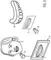
- a first important element is the three-dimensional model of the dentition 6 of the patient.
- Such three-dimensional model of the dentition has been obtained by scanning and/or phototechnical acquisition of the oral cavity of the patient, or by scanning the shape of the dentition taken as impressions in plastic material in impression trays.
- the three-dimensional model of the dental situation of the patient is symbolized by the upper jaw dentition 6.
- a virtual camera 8 is used in the computing device and acts on the three-dimensional model 6 to render a two-dimensional image 7 of the dentition of the patient, wherein an estimated position of the real camera 3 with respect to the face of the patient is used as a starting point for the position of the virtual camera 8. Since the estimated position of the camera 3 will deviate from the true position of the real camera 3 with respect to the face, there will be a certain deviation between each image 1 recorded by the camera 3 and the image 7 rendered by the virtual camera 8.
- the positioning of the virtual camera 8 is varied in an iterative optimization process which utilizes detected features of the dentition in the mouth opening of the image recorded by the camera on the one hand, and detected features in the image of the three-dimensional model of the dentition rendered by the virtual camera on the other hand.
- a measure of deviation or an error between the respective detected feature images is calculated and successively minimized in an iterative optimization process to determine a best fitting positioning of the virtual camera.
- This best fitting positioning of virtual camera can then be used on modified three-dimensional models of the dentitions which are modified for example by a planned dental treatment and which are referred to as three-dimensional models of a dental situation in the present application.
- a three-dimensional model of a dental situation which is derived from the three-dimensional model of the dentition of the patient and which may include replaced artificial teeth, dental restorations or corrected teeth positions can be visualized correctly positioned in the mouth opening of an image of the face of the patient displayed on a display.
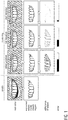
- FIG. 1 An example of feature detection in the images of the dentition is illustrated in Fig. 1 , wherein edges are detected in the respective images of the dentition.
- Fig. 1 an image including a mouth opening of a patient is shown in the first row on the left-hand side.
- the lip line is detected, and the region inside the lip line is selected as mouth opening region which is the only region further analyzed in the procedure.
- this image region of the mouth opening inside the lip line edge detection is performed which results in the detected edge image shown in the graph below the image recorded by the camera on the top on the left-hand side in Fig. 1 .
- the detected edges are mostly the bordering lines between adjacent teeth, the incisal edges and the borderlines where teeth bases and gingiva meet.
- FIG. 1 shows a rendered image on top which has been created by applying the virtual camera to the three-dimensional model of the dentition of the patient at the estimated positioning which the camera 3 had when recording the image of the mouth opening of the patient in the first column on top.
- the lip line detected in the image recorded by the camera is extracted and transferred to the rendered image and overlaid therein to select the mouth opening region of the dentition in the rendered image.
- edge detection is performed in the same manner as in the image recorded by the camera which results in the detected edge image shown in the second column in the second row.
- a difference image between the detected edge image of the image recorded by the camera and the detected edge image of the rendered image is formed which is shown in the second column in the third row.
- a measure of deviation is calculated from the difference image.
- the measure of deviation is calculated by integrating the absolute values of the intensities of all picture elements in the difference image. This measure of deviation is designated as error in Fig. 1 and is as a bar graph in the lowest row of Fig. 1 .
- a numerical optimization process now varies the positioning of the virtual camera in a first iteration to a new estimated positioning. Then the process of rendering the corresponding image from the three-dimensional model of the dentition using the new estimated positioning, of edge detection in the rendered image, and of forming the difference image between the detected edges in the image recorded by the camera and the detected edges in the rendered image of the first iteration is repeated as illustrated in the third column of Fig. 1 . As can be seen in the third line the difference image between the detected edges images of the image taken by the camera and the rendered image shows reduced intensities because the detected edges in the respective images are already in better agreement.
- Fig. 1 a second iteration is shown in the last column.
- the integrated intensity is further reduced which means that the measure of deviation is likewise reduced and already considerably smaller as indicated in the lowest row compared to the error at the estimated initial position.
- This numerical optimization process is repeated until further iterations do not further reduce the measure of deviation within the given or predetermined accuracy of the calculation.
- the positioning of the virtual camera corresponding to the minimized measure of deviation is stored as best fitting positioning of the virtual camera.
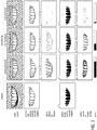
- Fig. 2 is a further illustration for an iterative optimization process optimizing the positioning of the virtual camera to fit to the positioning of the camera that recorded the real image including the mouth opening of the patient.
- the upper three rows show the same edge detection images and difference images between the detected edges in the image recorded by the camera and in the iteratively rendered images as shown in Fig. 1 .
- the fourth row shows the result of a color-based tooth likelihood determination in the respective images in the mouth opening within the lip line.
- this color-based tooth likelihood determination it is determined for the color values of each picture element the probability that it belongs to a teeth surface element. If for example a normalized probability density function for expected teeth color values is available this probability can be directly taken from the location of the color values in the probability distribution.
- the color of the teeth is differentiated from the color of the gingiva and the background of the oral cavity.
- the teeth visible in the images remain as black or mainly black objects with few grey elements in the images.
- the measure of deviation can then be formed as a first measure of deviation from the difference of the detected edges, for example by integrating the absolute values of the intensities over all picture elements of the difference image as described above.
- the same procedure can be applied to the difference image of the color-based tooth likelihood images for a second measure of deviation, wherein the first and second measure deviation may then be combined into a single measure of deviation designated as error in the last row of Fig. 2 .
- the positioning of the camera 3 when recording images of the face of the patient can be approximated by a corresponding positionings of the virtual camera rendering the three-dimensional model of the dentition of the patient to reach an optimal alignment.
- the best fitting positioning of the virtual camera can then for each image be used in further steps.
- a modified three-dimensional model of the dental situation can be used which differs from the three-dimensional model of the dental situation, e.g., to reflect the results of a potential dental treatment.
- the three-dimensional model of the dental situation after including the potential dental treatment may for example have one or more artificial teeth replacing the respective original teeth, or any other dental restorations.
- a further example of a dental situation may be the resulting corrected dentition after a teeth positioning correction treatment using dental braces.
- a further example of a dental situation may be based on the original dentition but include teeth position correction devices such as dental braces and retainers in place on the teeth of the dentition.
- the three-dimensional model of the dental situation representing the original state before any modification by a dental treatment is kept for further use in connection with the present invention, while the modified three-dimensional model of the dental situation after treatment is kept separately for further use.
- the modified three-dimensional model is referred to as the three-dimensional model of a dental situation for the patient.
- the virtual camera may then be applied to this three-dimensional model of the dental situation using the previously determined best fitting positioning of the camera to render an image of the dental situation. This rendered image may be inserted or overlaid in the mouth opening region of the image taken by the camera to provide a visualization of the dental situation.
- Teeth likelihood images are illustrated in a simplified manner in the fourth row of Fig. 2 .
Landscapes
- Health & Medical Sciences (AREA)
- Engineering & Computer Science (AREA)
- Physics & Mathematics (AREA)
- Oral & Maxillofacial Surgery (AREA)
- Theoretical Computer Science (AREA)
- General Physics & Mathematics (AREA)
- General Health & Medical Sciences (AREA)
- Computer Vision & Pattern Recognition (AREA)
- Epidemiology (AREA)
- Dentistry (AREA)
- Life Sciences & Earth Sciences (AREA)
- Animal Behavior & Ethology (AREA)
- Public Health (AREA)
- Veterinary Medicine (AREA)
- Multimedia (AREA)
- Human Computer Interaction (AREA)
- Geometry (AREA)
- Dental Tools And Instruments Or Auxiliary Dental Instruments (AREA)
Claims (7)
- Computerimplementiertes Verfahren zum Visualisieren von aus einem dreidimensionalen Modell einer Dentalsituation abgeleiteten zweidimensionalen Bildern in jedem Bild des Gesichts eines Patienten, das von einer Kamera in einer Videosequenz aufeinanderfolgender Bilder aufgenommen wird, wobei jedes Bild der Videosequenz die Mundöffnung des Patienten enthält, wobei das dreidimensionale Modell der Dentalsituation auf einem dreidimensionalen Modell des Gebisses des Patienten basiert und, im Vergleich zu dem dreidimensionalen Modell des Gebisses, Modifikationen aufgrund von Dentalbehandlung oder irgendeine andere Dentalmodifikation beinhaltet, wobei das Verfahren für jedes Bild der Videosequenz die Schritte aufweist:Ausrichten des dreidimensionalen Modells des Gebisses des Patienten zu dem von der Kamera (3) aufgenommenen Bild des Gesichts des Patienten, indem folgende Schritte ausgeführt werden:Schätzen der Positionierung der Kamera (3) relativ zum Gesicht des Patienten während der Aufnahme des Bildes undAufrufen des dreidimensionalen Modells (6) des Gebisses des Patienten,Generieren eines zweidimensionalen Bildes (7) des Gebisses des Patienten unter Verwendung der virtuellen Kamera (8), die das dreidimensionale Modell des Gebisses mit der geschätzten Positionierung prozessiert,Ausführen von Merkmalserkennung in einem Gebissgebiet in der Mundöffnung des von der Kamera (3) aufgenommenen Bildes (1) und in dem generierten Bild (7), indem Kantenerkennung und/oder eine farbbasierte Zahnwahrscheinlichkeitserkennung in den jeweiligen Bildern durchgeführt wird und ein Bild erkannter Merkmale mit dem oder mit jedem erkannten Merkmal gebildet wird,Analysieren des Bildes des Gesichts zur Erkennung einer die Mundöffnung umgebenden Lippenlinie, und wobei nur Bildelemente ausgewählt werden, die innerhalb der Lippenlinie liegen, um ein Abweichungsmaß in dem durch die Kamera aufgenommenen Bild zu bestimmen, wobei die Lippenlinie auch über das aus dem dreidimensionalen Modell des Gebisses generierte zweidimensionale Bild gelegt wird und nur die Region innerhalb der Lippenlinie verwendet wird, um im folgenden Schritt ein Abweichungsmaß zu bestimmen;Berechnen eines Abweichungsmaßes zwischen den Bildern erkannter Merkmale des durch die Kamera (3) aufgenommenen Bildes und des Bildes erkannter Merkmale des generierten Bildes,Variieren der Positionierung der virtuellen Kamera (8) zu einer neuen geschätzten Positionierung und Wiederholen der vorhergehenden vier Schritte in einem Optimierungsverfahren, um das Abweichungsmaß zu minimieren, um dadurch die am besten passende Positionierung der virtuellen Kamera (8) zu bestimmen,Generieren eines zweidimensionalen Bildes (7) der Dentalsituation aus dem dreidimensionalen Modell der Dentalsituation unter Verwendung der virtuellen Kamera (8), die die bestimmte am besten passende Positionierung für die virtuelle Kamera verwendet,wobei vor dem folgenden Schritt des Darüberlegenseine Bildregion eines Mundhöhlenhintergrundes innerhalb der Lippenlinie aus dem die Mundöffnung enthaltenden Bild in der Region zwischen dem unteren und dem oberen Zahnbogen erzeugt wird, und wobei die Bildregion innerhalb der Lippenlinie in dem durch die Kamera aufgenommenen Bild des Gesichts des Patienten ersetzt wird durch die erzeugte Bildregion des Mundhöhlenhintergrundes, undwobei die in dem durch die Kamera aufgenommenen Bild des Gesichts des Patienten detektierte Lippenlinie in das generierte Bild übertragen wird und über das generierte Bild gelegt wird und alle Bildelemente außerhalb der Lippenlinie in dem generierten Bild ausgeschlossen werden, wodurch das Gebiet des generierten Bildes herausgeschnitten wird, das der Mundöffnung entspricht,Darüberlegen des unter Verwendung der virtuelle Kamera generierten zweidimensionalen Bildes der Dentalsituation über das Bild des Gesichts des Patienten, das durch die Kamera aufgenommen ist, undAnzeigen des durch die Kamera aufgenommenen Bildes des Gesichts des Patienten mit dem darübergelegten, generierten zweidimensionalen Bild der Dentalsituation auf einer Anzeige (2).
- Computerimplementiertes Verfahren nach Anspruch 1, dadurch gekennzeichnet, dass die Merkmalserkennung durchgeführt wird, indem ausschließlich Kantenerkennung durchgeführt wird.
- Computerimplementiertes Verfahren nach Anspruch 2, dadurch gekennzeichnet, dass die erkannten Kanten auf Grundlage ihrer mittleren Richtungen aufgeteilt werden in horizontale Kanten und vertikale Kanten.
- Computerimplementiertes Verfahren nach Anspruch 1, dadurch gekennzeichnet, dass die Merkmalserkennung durchgeführt wird, indem Kantenerkennung und farbbasierte Zahnwahrscheinlichkeitserkennung durchgeführt werden, und dass ein kombiniertes Abweichungsmaß aus den Bildern erkannter Kanten und den erkannten farbbasierten Zahnwahrscheinlichkeitsbildern berechnet wird.
- Computerimplementiertes Verfahren nach Anspruch 1, dadurch gekennzeichnet, dass die Merkmalserkennung durchgeführt wird, indem nur farbbasierte Zahnwahrscheinlichkeitserkennung durchgeführt wird.
- Computerimplementiertes Verfahren nach einem der vorhergehenden Ansprüche, dadurch gekennzeichnet, dass das Abweichungsmaß berechnet wird, indem das Differenzbild aus dem Bild erkannter Merkmale des Bildes des Gesichts des Patienten, das durch die Kamera (3) aufgenommen worden ist, und dem Bild erkannter Merkmale des generierten Bildes gebildet wird und indem die Absolutwerte der Intensitäten des Differenzbildes über alle Bildelemente des Differenzbildes integriert werden.
- System zum Visualisieren zweidimensionaler Bilder einer Dentalsituation eines Patienten, die aus dreidimensionalen Modelldaten der Dentalsituation generiert werden, in jedem Bild des Gesichts des Patienten in einer Videosequenz aufeinanderfolgender, durch eine Kamera aufgenommener Bilder, wobei jedes Bild die Mundöffnung enthält, wobei das System aufweist:eine Kamera (3),eine Anzeige undeine Computereinheit (2), die betriebsmäßig mit der Kamera (3) und der Anzeige verbunden ist und die dazu vorbereitet ist, ein Verfahren gemäß Anspruch 1 durchzuführen.
Priority Applications (16)
| Application Number | Priority Date | Filing Date | Title |
|---|---|---|---|
| ES18157809T ES2882585T3 (es) | 2018-02-21 | 2018-02-21 | Procedimiento para alinear un modelo tridimensional de una dentadura de un paciente sobre una imagen del rostro del paciente grabada por una cámara |
| EP18157809.7A EP3530232B1 (de) | 2018-02-21 | 2018-02-21 | Verfahren zur ausrichtung eines dreidimensionalen modells eines gebisses eines patienten auf ein bild des gesichtes des patienten, das mit einer kamera aufgenommen wurde |
| DK18157809.7T DK3530232T3 (da) | 2018-02-21 | 2018-02-21 | Fremgangsmåde til at justere en tredimensionel model af en tandstilling af en patient til et billede af ansigtet af patienten optaget af et kamera |
| US16/967,942 US11544861B2 (en) | 2018-02-21 | 2019-02-13 | Method for aligning a three-dimensional model of a dentition of a patient to an image of the face of the patient recorded by camera |
| CA3091942A CA3091942A1 (en) | 2018-02-21 | 2019-02-13 | Method for aligning a three-dimensional model of a dentition of a patient to an image of the face of the patient |
| JP2020543902A JP7224361B2 (ja) | 2018-02-21 | 2019-02-13 | 患者の歯列の3次元モデルをカメラによって記録された患者の顔の画像に整合させるための方法 |
| PCT/EP2019/053557 WO2019162164A1 (en) | 2018-02-21 | 2019-02-13 | Method for aligning a three-dimensional model of a dentition of a patient to an image of the face of the patient |
| CN201980013859.7A CN111727022B (zh) | 2018-02-21 | 2019-02-13 | 用于将患者的牙列的三维模型与患者的面部图像对准的方法 |
| US16/278,444 US10779917B2 (en) | 2018-02-20 | 2019-02-18 | Computer implemented method for modifying a digital three-dimensional model of a dentition |
| US16/279,166 US10980621B2 (en) | 2018-02-20 | 2019-02-19 | Dental design transfer |
| US16/279,185 US11213374B2 (en) | 2018-02-20 | 2019-02-19 | Rendering a dental model in an image |
| US16/279,206 US11083552B2 (en) | 2018-02-20 | 2019-02-19 | Rendering of dental models |
| US16/279,229 US10803675B2 (en) | 2018-02-20 | 2019-02-19 | Dental model attributes transfer |
| US16/922,375 US11344392B2 (en) | 2018-02-20 | 2020-07-07 | Computer implemented method for modifying a digital three-dimensional model of a dentition |
| US16/923,261 US11244519B2 (en) | 2018-02-20 | 2020-07-08 | Dental model attributes transfer |
| US17/373,946 US20210338392A1 (en) | 2018-02-20 | 2021-07-13 | Rendering a dental model in an image |
Applications Claiming Priority (1)
| Application Number | Priority Date | Filing Date | Title |
|---|---|---|---|
| EP18157809.7A EP3530232B1 (de) | 2018-02-21 | 2018-02-21 | Verfahren zur ausrichtung eines dreidimensionalen modells eines gebisses eines patienten auf ein bild des gesichtes des patienten, das mit einer kamera aufgenommen wurde |
Publications (2)
| Publication Number | Publication Date |
|---|---|
| EP3530232A1 EP3530232A1 (de) | 2019-08-28 |
| EP3530232B1 true EP3530232B1 (de) | 2021-04-28 |
Family
ID=61256655
Family Applications (1)
| Application Number | Title | Priority Date | Filing Date |
|---|---|---|---|
| EP18157809.7A Active EP3530232B1 (de) | 2018-02-20 | 2018-02-21 | Verfahren zur ausrichtung eines dreidimensionalen modells eines gebisses eines patienten auf ein bild des gesichtes des patienten, das mit einer kamera aufgenommen wurde |
Country Status (8)
| Country | Link |
|---|---|
| US (1) | US11544861B2 (de) |
| EP (1) | EP3530232B1 (de) |
| JP (1) | JP7224361B2 (de) |
| CN (1) | CN111727022B (de) |
| CA (1) | CA3091942A1 (de) |
| DK (1) | DK3530232T3 (de) |
| ES (1) | ES2882585T3 (de) |
| WO (1) | WO2019162164A1 (de) |
Families Citing this family (17)
| Publication number | Priority date | Publication date | Assignee | Title |
|---|---|---|---|---|
| GB201802402D0 (en) * | 2018-02-14 | 2018-03-28 | Littlejohn Alexander | Apparatus and method for prosthodontics |
| CN114615951A (zh) | 2019-07-01 | 2022-06-10 | 约瑟夫·B·K·冯 | 利用混合现实引导牙科治疗的系统和方法 |
| GB201918008D0 (en) * | 2019-12-09 | 2020-01-22 | Univ Leeds Innovations Ltd | Determining spatial relationship between upper teeth and facial skeleton |
| GB201918006D0 (en) | 2019-12-09 | 2020-01-22 | Univ Leeds Innovations Ltd | Determining spatial relationship between upper and lower teeth |
| US12048605B2 (en) * | 2020-02-11 | 2024-07-30 | Align Technology, Inc. | Tracking orthodontic treatment using teeth images |
| CN111931843A (zh) * | 2020-08-10 | 2020-11-13 | 深圳爱舒笑科技有限公司 | 一种基于图像处理的监控牙齿位置的方法 |
| ES2992508T3 (es) * | 2020-10-13 | 2024-12-13 | Ivoclar Vivadent Ag | Procedimiento para configurar una restauración dental |
| CN112807108B (zh) * | 2021-01-27 | 2022-03-01 | 清华大学 | 一种正畸矫治过程中的牙齿矫治状态的检测方法 |
| US20220248957A1 (en) * | 2021-02-05 | 2022-08-11 | Abdullalbrahim ABDULWAHEED | Remote Patient Medical Evaluation Systems and Methods |
| EP4046594A1 (de) * | 2021-02-18 | 2022-08-24 | Ivoclar Vivadent AG | Verfahren zur festlegung einer zahnfarbe |
| EP4080454B1 (de) * | 2021-04-23 | 2024-08-07 | Ivoclar Vivadent AG | Verfahren zum exportieren eines dreidimensionalen ästhetischen dentalen modells aus einer anwendung der erweiterten realität auf eine rechnergestützte designanwendung |
| EP4346690B1 (de) * | 2021-06-01 | 2025-07-23 | Align Technology, Inc. | Automatisierte verwaltung klinischer modifikationen an behandlungsplänen mittels dreidimensionaler steuerungen |
| CN116035732B (zh) * | 2022-12-30 | 2025-11-18 | 上海时代天使医疗器械有限公司 | 面中线及牙齿矫治位置的确定方法、制造方法及系统 |
| KR102758841B1 (ko) * | 2022-03-22 | 2025-01-23 | 주식회사 레이 | 3차원 얼굴 스캔 시스템 및 그에 대한 3차원 얼굴 스캔 데이터 생성 방법 |
| US11633260B1 (en) | 2022-06-03 | 2023-04-25 | Sdc U.S. Smilepay Spv | Positioning individual three-dimensional model teeth based on two-dimensional images |
| KR102891748B1 (ko) * | 2023-01-04 | 2025-12-03 | 주식회사 레이 | 치아 보철물에 대한 시뮬레이션 수행 방법을 포함하는 컴퓨터 프로그램 |
| US12303348B2 (en) * | 2023-02-14 | 2025-05-20 | e32 Technology Inc. | Generating a 3D tooth modeling file adjusted for tooth size for manufacturing a 3D dental laminate |
Family Cites Families (11)
| Publication number | Priority date | Publication date | Assignee | Title |
|---|---|---|---|---|
| CA2672144A1 (en) * | 2006-04-14 | 2008-11-20 | Patrick Levy Rosenthal | Virtual video camera device with three-dimensional tracking and virtual object insertion |
| JP4514823B1 (ja) * | 2009-02-09 | 2010-07-28 | 株式会社スカイワーカーズ | 印刷物の画像識別方法および装置 |
| ES2944305T3 (es) * | 2010-06-29 | 2023-06-20 | 3Shape As | Disposición de imágenes en 2D |
| WO2014135695A1 (en) | 2013-03-08 | 2014-09-12 | 3Shape A/S | Visualising a 3d dental restoration on a 2d image |
| US20140379356A1 (en) * | 2013-06-20 | 2014-12-25 | Rohit Sachdeva | Method and system for integrated orthodontic treatment planning using unified workstation |
| AU2015361139B2 (en) * | 2014-12-09 | 2020-09-03 | Biomet 3I, Llc | Robotic device for dental surgery |
| US10248883B2 (en) * | 2015-08-20 | 2019-04-02 | Align Technology, Inc. | Photograph-based assessment of dental treatments and procedures |
| DE102015222782A1 (de) | 2015-11-18 | 2017-05-18 | Sirona Dental Systems Gmbh | Verfahren zur Visualisierung einer Zahnsituation |
| CN105581851A (zh) * | 2016-02-29 | 2016-05-18 | 深圳市古安泰自动化技术有限公司 | 可视化洗牙器 |
| CN105919684A (zh) * | 2016-05-27 | 2016-09-07 | 穆檬檬 | 一种建立三维牙颌融合模型的方法 |
| CN107139456B (zh) * | 2017-05-17 | 2019-08-20 | 上海联泰科技股份有限公司 | 三维物体数据的分层方法、3d打印方法及设备 |
-
2018
- 2018-02-21 EP EP18157809.7A patent/EP3530232B1/de active Active
- 2018-02-21 ES ES18157809T patent/ES2882585T3/es active Active
- 2018-02-21 DK DK18157809.7T patent/DK3530232T3/da active
-
2019
- 2019-02-13 CN CN201980013859.7A patent/CN111727022B/zh active Active
- 2019-02-13 CA CA3091942A patent/CA3091942A1/en active Pending
- 2019-02-13 JP JP2020543902A patent/JP7224361B2/ja active Active
- 2019-02-13 US US16/967,942 patent/US11544861B2/en active Active
- 2019-02-13 WO PCT/EP2019/053557 patent/WO2019162164A1/en not_active Ceased
Non-Patent Citations (1)
| Title |
|---|
| None * |
Also Published As
| Publication number | Publication date |
|---|---|
| US11544861B2 (en) | 2023-01-03 |
| CA3091942A1 (en) | 2019-08-29 |
| DK3530232T3 (da) | 2021-08-02 |
| CN111727022A (zh) | 2020-09-29 |
| ES2882585T3 (es) | 2021-12-02 |
| WO2019162164A1 (en) | 2019-08-29 |
| JP2021514232A (ja) | 2021-06-10 |
| JP7224361B2 (ja) | 2023-02-17 |
| EP3530232A1 (de) | 2019-08-28 |
| CN111727022B (zh) | 2022-07-15 |
| US20210366136A1 (en) | 2021-11-25 |
Similar Documents
| Publication | Publication Date | Title |
|---|---|---|
| EP3530232B1 (de) | Verfahren zur ausrichtung eines dreidimensionalen modells eines gebisses eines patienten auf ein bild des gesichtes des patienten, das mit einer kamera aufgenommen wurde | |
| JP7386215B2 (ja) | 歯列メッシュ矯正具除去のための方法および装置 | |
| JP7289026B2 (ja) | ハイブリッドメッシュセグメンテーションのための方法及び装置 | |
| US11344392B2 (en) | Computer implemented method for modifying a digital three-dimensional model of a dentition | |
| EP3349680B1 (de) | Verfahren zur erzeugung eines flexiblen bogenmodells der zähne zur verwendung in der restaurativen zahnmedizin | |
| CN109414306B (zh) | 用于口内扫描的历史扫描参考 | |
| JP5671734B2 (ja) | 顔面解析を用いた特注歯セットアップのコンピュータ支援作成 | |
| KR101799878B1 (ko) | 2d 영상 장치 | |
| KR20260030960A (ko) | 구강내 스캔을 위한 외부 개체 식별 및 이미지 증대 및/또는 필터링 | |
| US12569319B2 (en) | Combined face scanning and intraoral scanning | |
| US12056836B2 (en) | Dental model superimposition using clinical indications | |
| EP3629336B1 (de) | Übertragung eines zahnärztlichen entwurfs | |
| US11044400B1 (en) | Frame stitching in human oral cavity environment using intraoral camera | |
| US20250009471A1 (en) | Modeling a bite adjustment for an orthodontic treatment plan | |
| NL2037626B1 (en) | A computer-implemented method for digital tooth representation | |
| Elkholy et al. | Artificial intelligence in orthodontics: Part 2–Status quo | |
| CN114830179A (zh) | 确定上牙与面部骨骼之间的空间关系 | |
| WO2025224039A1 (en) | Computer-implemented methods, 3d cad system and apparatuses for estimating one or more scaling factors to map between a 2d digital image of a dentition and a 3d digital model of a dentition and jaw |
Legal Events
| Date | Code | Title | Description |
|---|---|---|---|
| PUAI | Public reference made under article 153(3) epc to a published international application that has entered the european phase |
Free format text: ORIGINAL CODE: 0009012 |
|
| STAA | Information on the status of an ep patent application or granted ep patent |
Free format text: STATUS: THE APPLICATION HAS BEEN PUBLISHED |
|
| AK | Designated contracting states |
Kind code of ref document: A1 Designated state(s): AL AT BE BG CH CY CZ DE DK EE ES FI FR GB GR HR HU IE IS IT LI LT LU LV MC MK MT NL NO PL PT RO RS SE SI SK SM TR |
|
| AX | Request for extension of the european patent |
Extension state: BA ME |
|
| STAA | Information on the status of an ep patent application or granted ep patent |
Free format text: STATUS: REQUEST FOR EXAMINATION WAS MADE |
|
| 17P | Request for examination filed |
Effective date: 20200128 |
|
| RBV | Designated contracting states (corrected) |
Designated state(s): AL AT BE BG CH CY CZ DE DK EE ES FI FR GB GR HR HU IE IS IT LI LT LU LV MC MK MT NL NO PL PT RO RS SE SI SK SM TR |
|
| GRAP | Despatch of communication of intention to grant a patent |
Free format text: ORIGINAL CODE: EPIDOSNIGR1 |
|
| STAA | Information on the status of an ep patent application or granted ep patent |
Free format text: STATUS: GRANT OF PATENT IS INTENDED |
|
| INTG | Intention to grant announced |
Effective date: 20201216 |
|
| GRAJ | Information related to disapproval of communication of intention to grant by the applicant or resumption of examination proceedings by the epo deleted |
Free format text: ORIGINAL CODE: EPIDOSDIGR1 |
|
| STAA | Information on the status of an ep patent application or granted ep patent |
Free format text: STATUS: REQUEST FOR EXAMINATION WAS MADE |
|
| GRAS | Grant fee paid |
Free format text: ORIGINAL CODE: EPIDOSNIGR3 |
|
| STAA | Information on the status of an ep patent application or granted ep patent |
Free format text: STATUS: GRANT OF PATENT IS INTENDED |
|
| INTC | Intention to grant announced (deleted) | ||
| RIN1 | Information on inventor provided before grant (corrected) |
Inventor name: LANCELLE, MARCEL Inventor name: BARTOLOVIC, NEMANJA Inventor name: DEGEN, NICOLAS Inventor name: SOEROES, GABOR Inventor name: MOERZINGER, ROLAND |
|
| GRAP | Despatch of communication of intention to grant a patent |
Free format text: ORIGINAL CODE: EPIDOSNIGR1 |
|
| GRAA | (expected) grant |
Free format text: ORIGINAL CODE: 0009210 |
|
| STAA | Information on the status of an ep patent application or granted ep patent |
Free format text: STATUS: THE PATENT HAS BEEN GRANTED |
|
| INTG | Intention to grant announced |
Effective date: 20210324 |
|
| AK | Designated contracting states |
Kind code of ref document: B1 Designated state(s): AL AT BE BG CH CY CZ DE DK EE ES FI FR GB GR HR HU IE IS IT LI LT LU LV MC MK MT NL NO PL PT RO RS SE SI SK SM TR |
|
| REG | Reference to a national code |
Ref country code: GB Ref legal event code: FG4D |
|
| REG | Reference to a national code |
Ref country code: CH Ref legal event code: EP Ref country code: CH Ref legal event code: NV Representative=s name: KELLER SCHNEIDER PATENT- UND MARKENANWAELTE AG, CH |
|
| REG | Reference to a national code |
Ref country code: DE Ref legal event code: R083 Ref document number: 602018016041 Country of ref document: DE |
|
| REG | Reference to a national code |
Ref country code: CH Ref legal event code: PK Free format text: BERICHTIGUNGEN |
|
| REG | Reference to a national code |
Ref country code: AT Ref legal event code: REF Ref document number: 1386246 Country of ref document: AT Kind code of ref document: T Effective date: 20210515 |
|
| RIN2 | Information on inventor provided after grant (corrected) |
Inventor name: LANCELLE, MARCEL Inventor name: MOERZINGER, ROLAND Inventor name: DEGEN, NICOLAS Inventor name: SOEROES, GABOR Inventor name: BARTOLOVIC, NEMANJA |
|
| REG | Reference to a national code |
Ref country code: DE Ref legal event code: R096 Ref document number: 602018016041 Country of ref document: DE |
|
| REG | Reference to a national code |
Ref country code: IE Ref legal event code: FG4D |
|
| RIN2 | Information on inventor provided after grant (corrected) |
Inventor name: LANCELLE, MARCEL Inventor name: MOERZINGER, ROLAND Inventor name: DEGEN, NICOLAS Inventor name: SOEROES, GABOR Inventor name: BARTOLOVIC, NEMANJA |
|
| REG | Reference to a national code |
Ref country code: DK Ref legal event code: T3 Effective date: 20210726 |
|
| REG | Reference to a national code |
Ref country code: LT Ref legal event code: MG9D |
|
| PG25 | Lapsed in a contracting state [announced via postgrant information from national office to epo] |
Ref country code: NL Free format text: LAPSE BECAUSE OF FAILURE TO SUBMIT A TRANSLATION OF THE DESCRIPTION OR TO PAY THE FEE WITHIN THE PRESCRIBED TIME-LIMIT Effective date: 20210428 Ref country code: HR Free format text: LAPSE BECAUSE OF FAILURE TO SUBMIT A TRANSLATION OF THE DESCRIPTION OR TO PAY THE FEE WITHIN THE PRESCRIBED TIME-LIMIT Effective date: 20210428 Ref country code: BG Free format text: LAPSE BECAUSE OF FAILURE TO SUBMIT A TRANSLATION OF THE DESCRIPTION OR TO PAY THE FEE WITHIN THE PRESCRIBED TIME-LIMIT Effective date: 20210728 Ref country code: FI Free format text: LAPSE BECAUSE OF FAILURE TO SUBMIT A TRANSLATION OF THE DESCRIPTION OR TO PAY THE FEE WITHIN THE PRESCRIBED TIME-LIMIT Effective date: 20210428 Ref country code: LT Free format text: LAPSE BECAUSE OF FAILURE TO SUBMIT A TRANSLATION OF THE DESCRIPTION OR TO PAY THE FEE WITHIN THE PRESCRIBED TIME-LIMIT Effective date: 20210428 |
|
| PG25 | Lapsed in a contracting state [announced via postgrant information from national office to epo] |
Ref country code: GR Free format text: LAPSE BECAUSE OF FAILURE TO SUBMIT A TRANSLATION OF THE DESCRIPTION OR TO PAY THE FEE WITHIN THE PRESCRIBED TIME-LIMIT Effective date: 20210729 Ref country code: IS Free format text: LAPSE BECAUSE OF FAILURE TO SUBMIT A TRANSLATION OF THE DESCRIPTION OR TO PAY THE FEE WITHIN THE PRESCRIBED TIME-LIMIT Effective date: 20210828 Ref country code: RS Free format text: LAPSE BECAUSE OF FAILURE TO SUBMIT A TRANSLATION OF THE DESCRIPTION OR TO PAY THE FEE WITHIN THE PRESCRIBED TIME-LIMIT Effective date: 20210428 Ref country code: SE Free format text: LAPSE BECAUSE OF FAILURE TO SUBMIT A TRANSLATION OF THE DESCRIPTION OR TO PAY THE FEE WITHIN THE PRESCRIBED TIME-LIMIT Effective date: 20210428 Ref country code: PL Free format text: LAPSE BECAUSE OF FAILURE TO SUBMIT A TRANSLATION OF THE DESCRIPTION OR TO PAY THE FEE WITHIN THE PRESCRIBED TIME-LIMIT Effective date: 20210428 Ref country code: PT Free format text: LAPSE BECAUSE OF FAILURE TO SUBMIT A TRANSLATION OF THE DESCRIPTION OR TO PAY THE FEE WITHIN THE PRESCRIBED TIME-LIMIT Effective date: 20210830 Ref country code: NO Free format text: LAPSE BECAUSE OF FAILURE TO SUBMIT A TRANSLATION OF THE DESCRIPTION OR TO PAY THE FEE WITHIN THE PRESCRIBED TIME-LIMIT Effective date: 20210728 Ref country code: LV Free format text: LAPSE BECAUSE OF FAILURE TO SUBMIT A TRANSLATION OF THE DESCRIPTION OR TO PAY THE FEE WITHIN THE PRESCRIBED TIME-LIMIT Effective date: 20210428 |
|
| REG | Reference to a national code |
Ref country code: ES Ref legal event code: FG2A Ref document number: 2882585 Country of ref document: ES Kind code of ref document: T3 Effective date: 20211202 |
|
| REG | Reference to a national code |
Ref country code: NL Ref legal event code: MP Effective date: 20210428 |
|
| PG25 | Lapsed in a contracting state [announced via postgrant information from national office to epo] |
Ref country code: CZ Free format text: LAPSE BECAUSE OF FAILURE TO SUBMIT A TRANSLATION OF THE DESCRIPTION OR TO PAY THE FEE WITHIN THE PRESCRIBED TIME-LIMIT Effective date: 20210428 Ref country code: RO Free format text: LAPSE BECAUSE OF FAILURE TO SUBMIT A TRANSLATION OF THE DESCRIPTION OR TO PAY THE FEE WITHIN THE PRESCRIBED TIME-LIMIT Effective date: 20210428 Ref country code: SK Free format text: LAPSE BECAUSE OF FAILURE TO SUBMIT A TRANSLATION OF THE DESCRIPTION OR TO PAY THE FEE WITHIN THE PRESCRIBED TIME-LIMIT Effective date: 20210428 Ref country code: SM Free format text: LAPSE BECAUSE OF FAILURE TO SUBMIT A TRANSLATION OF THE DESCRIPTION OR TO PAY THE FEE WITHIN THE PRESCRIBED TIME-LIMIT Effective date: 20210428 Ref country code: EE Free format text: LAPSE BECAUSE OF FAILURE TO SUBMIT A TRANSLATION OF THE DESCRIPTION OR TO PAY THE FEE WITHIN THE PRESCRIBED TIME-LIMIT Effective date: 20210428 |
|
| REG | Reference to a national code |
Ref country code: DE Ref legal event code: R097 Ref document number: 602018016041 Country of ref document: DE |
|
| PLBE | No opposition filed within time limit |
Free format text: ORIGINAL CODE: 0009261 |
|
| STAA | Information on the status of an ep patent application or granted ep patent |
Free format text: STATUS: NO OPPOSITION FILED WITHIN TIME LIMIT |
|
| 26N | No opposition filed |
Effective date: 20220131 |
|
| PG25 | Lapsed in a contracting state [announced via postgrant information from national office to epo] |
Ref country code: IS Free format text: LAPSE BECAUSE OF FAILURE TO SUBMIT A TRANSLATION OF THE DESCRIPTION OR TO PAY THE FEE WITHIN THE PRESCRIBED TIME-LIMIT Effective date: 20210828 Ref country code: AL Free format text: LAPSE BECAUSE OF FAILURE TO SUBMIT A TRANSLATION OF THE DESCRIPTION OR TO PAY THE FEE WITHIN THE PRESCRIBED TIME-LIMIT Effective date: 20210428 |
|
| PG25 | Lapsed in a contracting state [announced via postgrant information from national office to epo] |
Ref country code: MC Free format text: LAPSE BECAUSE OF FAILURE TO SUBMIT A TRANSLATION OF THE DESCRIPTION OR TO PAY THE FEE WITHIN THE PRESCRIBED TIME-LIMIT Effective date: 20210428 |
|
| REG | Reference to a national code |
Ref country code: BE Ref legal event code: MM Effective date: 20220228 |
|
| PG25 | Lapsed in a contracting state [announced via postgrant information from national office to epo] |
Ref country code: LU Free format text: LAPSE BECAUSE OF NON-PAYMENT OF DUE FEES Effective date: 20220221 |
|
| PG25 | Lapsed in a contracting state [announced via postgrant information from national office to epo] |
Ref country code: IE Free format text: LAPSE BECAUSE OF NON-PAYMENT OF DUE FEES Effective date: 20220221 |
|
| PG25 | Lapsed in a contracting state [announced via postgrant information from national office to epo] |
Ref country code: BE Free format text: LAPSE BECAUSE OF NON-PAYMENT OF DUE FEES Effective date: 20220228 |
|
| P01 | Opt-out of the competence of the unified patent court (upc) registered |
Effective date: 20230607 |
|
| REG | Reference to a national code |
Ref country code: AT Ref legal event code: UEP Ref document number: 1386246 Country of ref document: AT Kind code of ref document: T Effective date: 20210428 |
|
| PG25 | Lapsed in a contracting state [announced via postgrant information from national office to epo] |
Ref country code: MK Free format text: LAPSE BECAUSE OF FAILURE TO SUBMIT A TRANSLATION OF THE DESCRIPTION OR TO PAY THE FEE WITHIN THE PRESCRIBED TIME-LIMIT Effective date: 20210428 Ref country code: CY Free format text: LAPSE BECAUSE OF FAILURE TO SUBMIT A TRANSLATION OF THE DESCRIPTION OR TO PAY THE FEE WITHIN THE PRESCRIBED TIME-LIMIT Effective date: 20210428 |
|
| PG25 | Lapsed in a contracting state [announced via postgrant information from national office to epo] |
Ref country code: HU Free format text: LAPSE BECAUSE OF FAILURE TO SUBMIT A TRANSLATION OF THE DESCRIPTION OR TO PAY THE FEE WITHIN THE PRESCRIBED TIME-LIMIT; INVALID AB INITIO Effective date: 20180221 |
|
| PG25 | Lapsed in a contracting state [announced via postgrant information from national office to epo] |
Ref country code: MT Free format text: LAPSE BECAUSE OF FAILURE TO SUBMIT A TRANSLATION OF THE DESCRIPTION OR TO PAY THE FEE WITHIN THE PRESCRIBED TIME-LIMIT Effective date: 20210428 |
|
| PGFP | Annual fee paid to national office [announced via postgrant information from national office to epo] |
Ref country code: DE Payment date: 20250220 Year of fee payment: 8 |
|
| PGFP | Annual fee paid to national office [announced via postgrant information from national office to epo] |
Ref country code: DK Payment date: 20250225 Year of fee payment: 8 |
|
| PGFP | Annual fee paid to national office [announced via postgrant information from national office to epo] |
Ref country code: ES Payment date: 20250306 Year of fee payment: 8 |
|
| PGFP | Annual fee paid to national office [announced via postgrant information from national office to epo] |
Ref country code: AT Payment date: 20250221 Year of fee payment: 8 Ref country code: CH Payment date: 20250319 Year of fee payment: 8 |
|
| PGFP | Annual fee paid to national office [announced via postgrant information from national office to epo] |
Ref country code: FR Payment date: 20250226 Year of fee payment: 8 |
|
| PGFP | Annual fee paid to national office [announced via postgrant information from national office to epo] |
Ref country code: IT Payment date: 20250108 Year of fee payment: 8 Ref country code: GB Payment date: 20250225 Year of fee payment: 8 |
|
| PG25 | Lapsed in a contracting state [announced via postgrant information from national office to epo] |
Ref country code: TR Free format text: LAPSE BECAUSE OF FAILURE TO SUBMIT A TRANSLATION OF THE DESCRIPTION OR TO PAY THE FEE WITHIN THE PRESCRIBED TIME-LIMIT Effective date: 20210428 |