EP3983231B1 - Multi-functional print head for a stencil printer - Google Patents
Multi-functional print head for a stencil printer Download PDFInfo
- Publication number
- EP3983231B1 EP3983231B1 EP20751711.1A EP20751711A EP3983231B1 EP 3983231 B1 EP3983231 B1 EP 3983231B1 EP 20751711 A EP20751711 A EP 20751711A EP 3983231 B1 EP3983231 B1 EP 3983231B1
- Authority
- EP
- European Patent Office
- Prior art keywords
- stencil printer
- stencil
- delivery device
- items
- movable cart
- Prior art date
- Legal status (The legal status is an assumption and is not a legal conclusion. Google has not performed a legal analysis and makes no representation as to the accuracy of the status listed.)
- Revoked
Links
Images


Classifications
-
- B—PERFORMING OPERATIONS; TRANSPORTING
- B41—PRINTING; LINING MACHINES; TYPEWRITERS; STAMPS
- B41M—PRINTING, DUPLICATING, MARKING, OR COPYING PROCESSES; COLOUR PRINTING
- B41M1/00—Inking and printing with a printer's forme
- B41M1/12—Stencil printing; Silk-screen printing
-
- B—PERFORMING OPERATIONS; TRANSPORTING
- B41—PRINTING; LINING MACHINES; TYPEWRITERS; STAMPS
- B41F—PRINTING MACHINES OR PRESSES
- B41F15/00—Screen printers
- B41F15/14—Details
- B41F15/34—Screens, Frames; Holders therefor
-
- B—PERFORMING OPERATIONS; TRANSPORTING
- B41—PRINTING; LINING MACHINES; TYPEWRITERS; STAMPS
- B41L—APPARATUS OR DEVICES FOR MANIFOLDING, DUPLICATING OR PRINTING FOR OFFICE OR OTHER COMMERCIAL PURPOSES; ADDRESSING MACHINES OR LIKE SERIES-PRINTING MACHINES
- B41L13/00—Stencilling apparatus for office or other commercial use
- B41L13/02—Stencilling apparatus for office or other commercial use with flat stencil carriers
-
- B—PERFORMING OPERATIONS; TRANSPORTING
- B41—PRINTING; LINING MACHINES; TYPEWRITERS; STAMPS
- B41F—PRINTING MACHINES OR PRESSES
- B41F15/00—Screen printers
- B41F15/08—Machines
-
- B—PERFORMING OPERATIONS; TRANSPORTING
- B41—PRINTING; LINING MACHINES; TYPEWRITERS; STAMPS
- B41F—PRINTING MACHINES OR PRESSES
- B41F15/00—Screen printers
- B41F15/14—Details
-
- B—PERFORMING OPERATIONS; TRANSPORTING
- B41—PRINTING; LINING MACHINES; TYPEWRITERS; STAMPS
- B41F—PRINTING MACHINES OR PRESSES
- B41F15/00—Screen printers
- B41F15/14—Details
- B41F15/16—Printing tables
- B41F15/18—Supports for workpieces
-
- B—PERFORMING OPERATIONS; TRANSPORTING
- B41—PRINTING; LINING MACHINES; TYPEWRITERS; STAMPS
- B41F—PRINTING MACHINES OR PRESSES
- B41F15/00—Screen printers
- B41F15/14—Details
- B41F15/34—Screens, Frames; Holders therefor
- B41F15/36—Screens, Frames; Holders therefor flat
-
- B—PERFORMING OPERATIONS; TRANSPORTING
- B41—PRINTING; LINING MACHINES; TYPEWRITERS; STAMPS
- B41F—PRINTING MACHINES OR PRESSES
- B41F15/00—Screen printers
- B41F15/14—Details
- B41F15/40—Inking units
-
- B—PERFORMING OPERATIONS; TRANSPORTING
- B41—PRINTING; LINING MACHINES; TYPEWRITERS; STAMPS
- B41F—PRINTING MACHINES OR PRESSES
- B41F15/00—Screen printers
- B41F15/14—Details
- B41F15/44—Squeegees or doctors
-
- B—PERFORMING OPERATIONS; TRANSPORTING
- B41—PRINTING; LINING MACHINES; TYPEWRITERS; STAMPS
- B41F—PRINTING MACHINES OR PRESSES
- B41F33/00—Indicating, counting, warning, control or safety devices
- B41F33/0009—Central control units
-
- B—PERFORMING OPERATIONS; TRANSPORTING
- B41—PRINTING; LINING MACHINES; TYPEWRITERS; STAMPS
- B41N—PRINTING PLATES OR FOILS; MATERIALS FOR SURFACES USED IN PRINTING MACHINES FOR PRINTING, INKING, DAMPING, OR THE LIKE; PREPARING SUCH SURFACES FOR USE AND CONSERVING THEM
- B41N1/00—Printing plates or foils; Materials therefor
- B41N1/24—Stencils; Stencil materials; Carriers therefor
- B41N1/248—Mechanical details, e.g. fixation holes, reinforcement or guiding means; Perforation lines; Ink holding means; Visually or otherwise detectable marking means; Stencil units
-
- B—PERFORMING OPERATIONS; TRANSPORTING
- B41—PRINTING; LINING MACHINES; TYPEWRITERS; STAMPS
- B41P—INDEXING SCHEME RELATING TO PRINTING, LINING MACHINES, TYPEWRITERS, AND TO STAMPS
- B41P2215/00—Screen printing machines
- B41P2215/10—Screen printing machines characterised by their constructional features
Definitions
- This application relates generally to stencil printers and related methods to print viscous materials, e.g., solder paste, on an electronic substrate, e.g., a printed circuit board (PCB), and more particularly to systems and methods for fully automating such stencil printers and methods.
- viscous materials e.g., solder paste
- PCB printed circuit board
- a stencil printer can be used to print solder paste onto the circuit board.
- a circuit board having a pattern of pads or some other conductive surface onto which solder paste will be deposited is automatically fed into the stencil printer; and one or more small holes or marks (known as "fiducials") on the circuit board are used to properly align the circuit board with the stencil or screen of the stencil printer prior to printing solder paste onto the circuit board.
- an optical alignment system embodying a vision system is used to align the circuit board with the stencil.
- US2002019680 discloses a method for controlling a screen printer.
- the circuit board is raised to the stencil, solder paste is dispensed onto the stencil, and a wiper blade (or squeegee) traverses the stencil to force the solder paste through apertures in the stencil and onto the circuit board.
- a wiper blade or squeegee traverses the stencil to force the solder paste through apertures in the stencil and onto the circuit board.
- the solder paste tends to roll in front of the blade, which desirably causes mixing and shearing of the solder paste so as to attain a desired viscosity to facilitate filling of the apertures in the screen or stencil.
- the solder paste typically is dispensed onto the stencil from a standard cartridge.
- the stencil is then separated from the circuit board and the adhesion between the circuit board and the solder paste causes most of the material to stay on the circuit board. Material left on the surface of the stencil is removed in a cleaning process before additional circuit boards are printed.
- Another process in the printing of circuit boards involves inspection of the circuit boards after solder paste has been deposited on the surface of the circuit boards. Inspecting the circuit boards is important for determining that clean electrical connections can be made. An excess of solder paste can lead to shorts, while too little solder paste in appropriate positions can prevent electrical contact. Generally, the vision inspection system is further employed to provide a two-dimensional or a three-dimensional inspection of the solder paste on the circuit board.
- Present day stencil printers require manual intervention to perform routine operations. For example, during a changeover, an operator must perform many manual tasks, such as changing a stencil, replacing a solder paste cartridge, replacing squeegee blades, and replacing support tooling. Each of these tasks require the operator to manually perform the task. For example, with most stencil printers, the operator must unlock the stencil, remove the stencil, properly insert a replacement stencil, and lock the replacement stencil in place.
- a changeover operation can take as long as 30 minutes, during which the stencil printer is not operating, which may result in the PCB fabrication line not operating.
- Stencil printers further require manual intervention to perform replacement and/or replenishment operations.
- solder paste cartridges which supply temperature-controlled solder paste to the stencil printer, require replacement over time, e.g., within four hours or less. Items subject to normal wear and tear, such as squeegee blades and stencils, may require periodic replacement when damaged.
- the present disclosure relates generally to material application machines (referred to herein as “stencil printers,” “screen printers,” “printing machines,” or “printers”) and other equipment utilized in a surface mount technology (SMT) process lines and configured to apply an assembly material (e.g., solder paste, conductive ink, or encapsulation material) onto a substrate (e.g., a printed circuit board, referred to herein as an "electronic substrate,” a “circuit board,” a “board,” a “PCB,” a “PCB substrate,” a “substrate,” or a “PCB board”) or to perform other operations, such as inspection, rework, or placement of electronic components onto a substrate.
- a substrate e.g., a printed circuit board, referred to herein as an "electronic substrate,” a “circuit board,” a “board,” a “PCB,” a “PCB substrate,” a “substrate,” or a “PCB board”
- references in the singular or plural form are not intended to limit the presently disclosed systems or methods, their components, acts, or elements.
- the use herein of "including,” “comprising,” “having,” “containing,” “involving,” and variations thereof is meant to encompass the items listed thereafter as well as additional items.
- References to “or” may be construed as inclusive so that any terms described using “or” may indicate any of a single, more than one, and all of the described terms.
- stencil printer used to print an assembly material, such as solder paste, onto a circuit board.
- assembly material such as solder paste
- embodiments of the present disclosure are not limited to stencil printers that print solder paste onto circuit boards, but rather, may be used in other applications requiring dispensing of other viscous assembly materials, such as glues and encapsulents.
- the apparatus may be used to print epoxy for use as underfill for chip-scale packages.
- stencil printers in accordance with embodiments of the present disclosure are not limited to those that print assembly materials on circuit boards, but rather, include those used for printing other materials on a variety of substrates, such as semiconductor wafers.
- the terms screen and stencil may be used interchangeably herein to describe a device in a printer that defines a pattern to be printed onto a substrate.
- the stencil printer may include a Momentum ® or an Edison TM series stencil printer platform offered by ITW Electronic Assembly Equipment of Hopkinton, Massachusetts.
- An exemplary stencil printer is generally designated at 5 in FIG. 1 .
- the stencil printer 5 is a Momentum ® series stencil printer platform offered by ITW Electronic Assembly Equipment of Hopkinton, Massachusetts.
- the stencil printer 10 includes a frame 12 that supports components of the stencil printer.
- the components of the stencil printer may include, in part, a controller 14, a display 16, a stencil 18, and a print head or print head assembly, generally indicated at 20, which is configured to apply the solder paste in a manner described in greater detail below.
- the stencil and the print head assembly may be suitably coupled or otherwise connected to the frame 12.
- the print head assembly 20 may be mounted on a print head assembly gantry 22, which may be mounted on the frame 12.
- the print head assembly gantry 22 enables the print head assembly 20 to be moved in the y-axis direction under the control of the controller 14 and to apply pressure on the print head assembly as it engages the stencil 18.
- the print head assembly 20 may be placed over the stencil 18 and may be lowered in the z-axis direction into contact and sealingly engage the stencil.
- the stencil printer 10 may also include a conveyor system having rails (not shown) for transporting a printed circuit board (sometimes referred to as a "printed wiring board,” “substrate,” or “electronic substrate” herein) to a print position in the stencil printer.
- the rails sometimes may be referred to herein as a “tractor feed mechanism,” which is configured to feed, load or otherwise deliver circuit boards to the working area of the stencil printer, which may be referred to herein as a "print nest,” and to unload circuit boards from the print nest.
- the stencil printer 10 has a support assembly 28 to support the circuit board 29 (shown in dashed lines), which raises and secures the circuit board so that it is stable during a print operation.
- the substrate support assembly 28 further may include a particular substrate support system, e.g., a solid support, a plurality of pins or flexible tooling, which is positioned beneath the circuit board when the circuit board is in the print position.
- the substrate support system may be used, in part, to support the interior regions of the circuit board to prevent flexing or warping of the circuit board during the print operation.
- the print head assembly 20 may be configured to receive solder paste from a source, such as a dispenser, e.g., a solder paste cartridge, that provides solder paste to the print head assembly during the print operation.
- a source such as a dispenser, e.g., a solder paste cartridge
- Other methods of supplying solder paste may be employed in place of the cartridge.
- solder paste may be manually deposited between the blades or from an external source.
- the controller 14 may be configured to use a personal computer having a suitable operating system, such as a Microsoft Windows ® operating system provided by Microsoft Corporation, with application specific software to control the operation of the stencil printer 10.
- the controller 14 may be networked with a master controller that is used to control a production line for fabricating circuit boards.
- the stencil printer 10 operates as follows. A circuit board 29 is loaded into the stencil printer 10 using the conveyor rails. The support assembly 28 raises and secures the circuit board 29 to a print position. The print head assembly 20 is then lowered in the z-axis direction until blades of the print head assembly contact the stencil 18 at a desired pressure. The print head assembly 20 is then moved in the y-axis direction across the stencil 18 by the print head assembly gantry 22. The print head assembly 20 deposits solder paste through apertures in the stencil 18 and onto the circuit board 29. Once the print head assembly has fully traversed the stencil 18 across the apertures, the print head assembly is lifted off the stencil and the circuit board 29 is lowered back onto the conveyor rails.
- the circuit board 29 is released and transported from the stencil printer 10 so that a second circuit board may be loaded into the stencil printer.
- the print head assembly is lowered in the z-axis direction into contact with the stencil and moved across the stencil 18 in the direction opposite to that used for the first circuit board.
- An imaging system 30 may be provided for the purposes of aligning the stencil 18 with the circuit board 29 prior to printing and to inspect the circuit board after printing.
- the imaging system 30 may be disposed between the stencil 18 and the support assembly 28 upon which a circuit board is supported.
- the imaging system 30 is coupled to an imaging gantry 32 to move the imaging system.
- the imaging gantry 32 may be coupled to the frame 12, and includes a beam that extends between side rails of the frame 12 to provide back and forth movement of the imaging system 30 over the circuit board 29 in a y-axis direction.
- the imaging gantry 32 further may include a carriage device, which houses the imaging system 30, and is configured to move along the length of the beam in an x-axis direction.
- the construction of the imaging gantry 32 used to move the imaging system 30 is well known in the art of solder paste printing.
- the arrangement is such that the imaging system 30 may be located at any position below the stencil 18 and above the circuit board 29 to capture an image of predefined areas of the circuit board or the stencil, respectively.
- excess solder paste may accumulate at the bottom of the stencil 18 and a stencil wiper assembly, generally indicated at 34, and may move beneath the stencil to remove the excess solder paste. In other embodiments, the stencil 18 may be moved over the stencil wiper assembly.
- stencil printers require manual intervention to perform replacement of certain parts and/or replenishment operations. For example, a typical stencil requires replacement after a certain period of time, e.g., four hours. Also, stencils need replacement for separate production runs. In addition, solder paste cartridges, which supply temperature-controlled solder paste to the stencil printer, require replacement over time, e.g., within four hours or less. A separate production run may require a different solder paste material. Another item requiring periodic replacement is squeegee blades, which are subject to wearing during use. And finally, tooling used to support a substrate in a print position is subject to replacement when changing from one production product to another.
- a system and method of replacing tooling used to support a substrate in a print position includes, either for a new production run or because of a defect detected with existing tooling, retrieving new tooling from a tooling stockroom and transported to one of several stencil printers.
- the used tooling is removed from the stencil printer and the new tooling is inserted into the stencil printer and secured for use.
- the used tooling is transported to a station where the tooling is inspected, and if salvageable, cleaned for reuse. If defective, the tooling is scrapped in a responsible manner. Once cleaned, the tooling is transported back to the tooling stockroom, where the tooling is ready to be used during the same or different production run.
- a system and method of replacing a squeegee blade or a pair of squeegee blades includes, either for a new production run or because of a defect detected with an existing squeegee blade, retrieving a new squeegee blade from a squeegee blade stockroom and transporting the new squeegee blade to one of several stencil printers.
- the used squeegee blade is removed from the stencil printer and the new squeegee blade is inserted into the stencil printer and secured for use.
- the used squeegee blade is transported to a station where the squeegee blade is inspected, and if salvageable, cleaned for reuse.
- the squeegee blade is scrapped in a responsible manner. Once cleaned, the squeegee blade is transported back to the squeegee blade stockroom, where the squeegee blade is ready to be used during the same or different production run.
- a system and method of replacing a paste cartridge includes retrieving a new paste cartridge from a paste cartridge stockroom and transporting the new paste cartridge to one of several stencil printers.
- the stencil printers can be part of a single production line used to fabricate printed circuit boards or part of several production lines. The number of stencil printers can vary.
- the storage of the paste cartridges in the stockroom and the transportation of the paste cartridge should take place in a temperature- and/or climate-controlled environment suitable to preserve the solder paste contained within the solder paste cartridges.
- the "spent" or used paste cartridge is removed from the stencil printer and the "full” or new paste cartridge is inserted into the stencil printer and secured for use.
- the spent paste cartridge is transported to a station where the paste cartridge is saved (because it is not completely used) or saved for recycling. Once saved or recycled, the paste cartridge is transported back to the paste cartridge stockroom, where the paste cartridge is ready to be used during the same or different production run.
- Embodiments of the present disclosure are directed to a delivery system that is configured to automate a changeover process for a stencil printer and to implement one or more of the systems and methods described herein.
- the delivery system includes a movable cart that is configured to engage a stencil printer to supply and receive replacement and replenishment parts and materials to the stencil printer.
- the stencil printer may include a docking station that is configured to receive the movable cart.
- the docking station may include an interface that enables the movable cart to communicate with the stencil printer.
- a single movable cart may be configured to include replacement support tooling, replacement squeegee blades, replenishment squeegee blades, replacement solder paste cartridges, and replenishment solder paste cartridges.
- the stencil printer must be reconfigured to produce different items.
- a new support tool to accommodate a different substrate, a new blades having different lengths, and a different type of solder paste may be employed within the stencil printer to produce a different product.
- the changeover process described herein can be achieved by a single movable cart that is configured to replace and/or replenish each item. In other embodiments, more than one movable cart can be provided.
- the movable cart or another movable cart, is configured to support a predetermined number of tooling used to support a printed circuit board in a print position, which is selected for production runs anticipated for a particular day or a particular period of time.
- the movable cart and/or the stencil printer can be configured to identify the support tooling, store the support tooling, transport the support tooling to and from the stencil printer, inspect the support tooling, and interface with the stencil printer.
- the movable cart also may be configured to remove used parts, such as support tooling, from the stencil printer.
- the movable cart or another movable cart, is configured to support a predetermined number of squeegee blades, which are selected for production runs anticipated for a particular day or a particular period of time.
- the movable cart and/or the stencil printer can be configured to identify the squeegee blades, store the squeegee blades, transport the squeegee blades to and from the stencil printer, inspect the squeegee blades, and interface with the stencil printer.
- the movable cart also may be configured to remove used parts, such as squeegee blades, from the stencil printer.
- the movable cart is configured to support a predetermined number of paste cartridges, which are selected for production runs anticipated for a particular day or a particular period of time.
- the movable cart and/or the stencil printer can be configured to identify the paste cartridges, store the paste cartridges in a suitable environment, transport the paste cartridges to and from the stencil printer, inspect the paste cartridges, and interface with the stencil printer.
- the movable cart also may be configured to remove used parts, such as paste cartridges, from the stencil printer.
- the movable cart can be configured to store paste cartridges long term. In one embodiment, long term storage of solder paste can be achieved by refrigeration at 0 to 10 °C (32 to 50 °F).
- the paste cartridges can be stored at a location in the movable cart to maintain this temperature range.
- the movable cart can be configured to pre-heat the paste cartridges prior to use to ready the cartridges for use in the stencil printer.
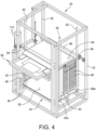
- a movable cart in one embodiment, includes a frame or housing 42 configured to support replacement and/or replenishment items. As shown, the frame 42 is generally rectangular and is supported on wheels or casters (not shown).
- the movable cart 40 is configured to be manually moved by an operator by pushing the frame 42 of the movable cart. In this embodiment, the movable cart 40 can be configured with a push bar or a handle. In another embodiment, the movable cart 40 is configured to be automatically moved, either by remote control or by an automated control associated with the movable cart, the stencil printer 10, the production line, and/or some other dedicated control.
- the movable cart 40 can include wheels that are driven by a suitable motor and drive train, and a control associated with the movable cart, the stencil printer 10, the production line, and/or some other dedicated control is configured to control the movable cart.
- the movable cart 40 further can include one or more sensors and/or a vision system, e.g., cameras, to guide the movable cart from a stockroom, for example, to the stencil printer.
- the movable cart 40 includes a translatable carriage, generally indicated at 44, that can be configured to support one or more items, such as replacement stencils, replacement support tooling, replacement and/or replenishment squeegee blades, and replacement and/or replenishment paste cartridges.
- the translatable carriage 44 includes a rectangular structure 46 having a top 48, a bottom 50, opposite sides 52, 54, an open front, and an open back.
- the sides 52, 54 of the structure 46 can includes slots, each indicated at 56, each slot being configured to receive and support opposite edges of a planar item, such as the stencil 18, or, in the shown embodiment, a tooling tray, generally indicated at 60.
- the structure 46 can be configured to receive several items, e.g., ten or more.
- the space between slots 56 can be sized to receive a standard stencil frame therein.
- the translatable carriage 44 further includes four vertically oriented rods, each indicated at 62, positioned at the four corners of the structure 46.
- the top of the structure 46 includes two bar members 64, 66, with one bar member 64 being secured to the top 48 of the structure adjacent the open front of the structure and the other bar member 66 being secured to the top adjacent the open back.
- the bottom of the structure 46 includes two bar members 64a, 66a, with one bar member 64a being secured to the bottom 50 of the structure adjacent the open front of the structure and the other bar member 66a being secured to the bottom adjacent the open back.
- Each bar member 64, 64a and 66, 66a includes two openings formed on opposite ends of the bar, with the openings being positioned to receive a respective rod therein.
- the arrangement is such that the structure 46 is capable of moving vertically with respect to the rods 62 to raise and lower the structure.
- a suitable mechanism can be provided to raise and lower the structure 46 under the control of a controller.
- a ball screw drive assembly can be provided to move the structure 46 to position a "shelf' defined by a slot 56 adjacent the stencil printer 10.
- the "shelves" can be specifically designed to support the tooling tray 60, which can be configured to support items including, but not limited to new and used support tooling, new and used squeegee blades, and new and spent/used paste cartridges.
- Some shelves can include tooling trays 60 that are designated as "clean shelves” to support clean or new items ready to be used within the stencil printer 10.
- Some shelves can include tooling trays 60 that are designated as "dirty shelves" to support used items to be taken away from the stencil printer 10.
- the space between the slots 56 can be spaced apart from one another specific distances to receive various items.
- the shelves can be spaced apart 3/8-inch to 11 ⁇ 2-inch from one another to accommodate stencil frame and tooling tray thicknesses.
- the movable cart 40 can be configured with one or more devices used to transport items from the movable cart to the stencil printer 10 and from the stencil printer to the movable cart.
- the device can include a transport arm 68 that is configured to push and retrieve stencils 18 and tooling trays 60 to and from the movable cart 40, respectively.
- the transport arm 68 is pushing the tooling tray 60 away from the movable cart 40, with the tooling tray being positioned to be received by the stencil printer.
- Any suitable mechanism can be provided to move the transport arm, such as a ball screw drive assembly.
- the tooling tray 60 includes a rectangular or square frame 70 and a planar body 72.
- the frame 70 can be sized to replicate the frame of the stencil 18.
- the tooling tray 60 can be fabricated from lightweight yet strong material, such as an aluminum alloy.
- the body 72 of the tooling tray 60 can include several cut outs, each indicated at 74, and several recesses, each indicated at 76, to receive support tooling and squeegee blade assemblies, respectively.
- the cut outs 74 are configured to receive and secure support tooling, each indicated at 78, which is provided to support the electronic substrate 29 during a stencil print operation.
- the recesses 76 are configured to receive and secure squeegee blade assemblies, each indicated at 80, which are used by the print head assembly 20 to perform a stencil print operation.
- the tooling tray 60 is substantially the same in form-factor as a stencil to permit handling and storage/retrieval of the tooling tray in substantially the same manner as a stencil.
- the movable cart 40 and the tooling tray 60 are particularly suited to handle stencils and tooling trays in a common manner.
- the movable cart 40 is configured to partially deliver the tooling tray 60 from the movable cart to the stencil printer 10, and the stencil printer is configured to receive the tooling tray the rest of the way.
- the transport arm 68 can be used to push the tooling tray 60 away from the carriage 44 and to retrieve the tooling tray into the carriage.
- the tooling tray 60 can include fiducials, which can be viewed by the imaging system 30 of the stencil printer 10 to establish alignment to the parts and locations on the tooling tray.
- a method of aligning to the tooling tray 60 can be employed by capturing and analyzing fiducial locations.
- the print head assembly 20 of the stencil printer 10 includes an end effector 82, which can be configured to pick up and release items from the tooling tray 60.
- the print head assembly 20 is mounted on the print head assembly gantry 22, which moves the print head assembly in the y-axis direction under the control of the controller 14.
- the print head assembly 22 is configured to move in the z-axis direction as described above.
- the end effector 82 can be configured to pick up and release a squeegee blade assembly 80.
- the end effector 82 is configured to toolessly engage and disengage the squeegee blade assembly 80 to attach and remove the squeegee blade assembly from the print head assembly 20.
- the tooling tray 60 is configured with a spring-loaded locking mechanism to secure a squeegee blade holder of the squeegee blade assembly 80 to the end effector 82 of the print head assembly 20.
- a method of passively picking up and dropping off squeegee blade assemblies 80 without needing additional axes or actuators can be performed by the end effector 82.
- the end effector 82 includes a rectangularly-shaped body 84 that is secured to the print head assembly 20 by a pair of connecting rods, each indicated at 86.
- the end effector 82 further includes a pair of downwardly extending pins ( FIG. 7C ), each indicated at 88, with each pin having a notch 90, the purpose of which will be described as the description of the mechanism proceeds.
- the squeegee blade assembly 80 includes a holder 92 having an L-shaped recess 94 formed therein.
- the recess 94 includes a vertical portion 94a and a horizontal portion 94b.
- the mechanism includes a spring-loaded pin 96 that is housed within the horizontal portion 94b of the recess 94, which is biased toward the vertical portion 94a of the recess by a spring 98.
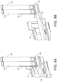
- FIGS. 7A and 7B illustrate the pin 88 of the end effector 82 entering the vertical portion 94a of the recess 94.
- a sloped portion of the pin engages a corresponding sloped portion of the spring-loaded pin 96.
- the downward movement of the pin 88 causes the spring-loaded pin 96 to move against the bias of the spring 98 until the notch 90 of the pin receives an engaging element 100 of the spring-loaded pin to engage and secure the holder 92 of the squeegee blade assembly 80 to the end effector 82.
- FIG. 7A and 7B illustrate the pin 88 of the end effector 82 entering the vertical portion 94a of the recess 94.
- a sloped portion of the pin engages a corresponding sloped portion of the spring-loaded pin 96.
- the downward movement of the pin 88 causes the spring-loaded pin 96 to move against the bias of the spring 98 until the notch 90 of the pin receives an engaging element 100 of the spring-loaded pin to engage and
- FIG. 7C illustrates both pins 88 being secured by their respective spring-loaded pins 96 to secure the holder 92 of the squeegee blade assembly 80.
- the end effector 82 secures the squeegee blade assembly 80 in which the squeegee blade assembly can be employed to perform a stencil print operation.
- FIGS. 8A and 8B illustrate the pin 88 of the end effector 82 being retracted from the vertical portion 94a of the recess 94.
- An upwardly projecting element 102 is provided on the tooling tray 60 to move the spring-loaded pin 96 from the engaged position illustrated in FIGS. 7B and 7C to the disengaged position illustrated in FIG. 7A .
- a sloped portion of the element 102 engages a corresponding sloped portion formed on the spring-loaded pin 96.
- the downward movement of the end effector 82 toward the element 102 causes the spring-loaded pin 96 to move against the bias of the spring 98 until the engaging element 100 of the spring-loaded pin is removed from the notch 90 of the pin 88 to release the squeegee blade assembly 80 from the end effector 82, which is shown in FIG 8B .
- the element 102 maintains the spring-loaded pin 96 in the disengaged position thereby enabling the release of the holder 92 of the squeegee blade assembly 80.
- the end effector 82 can employ magnets to engage magnetic material associated with the squeegee blade assembly 80 to secure and release the squeegee blade assembly to the print head assembly 20.
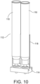
- the movable cart 40 includes replacement paste cartridges, each indicated at 110.
- the paste cartridges 110 are supported on a paste cartridge staging area of the movable cart 40, otherwise referred to as an "on-deck-circle," which permits the stencil printer 10 to be continuously fed solder paste for uninterrupted operation.
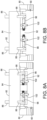
- the frame 12 of the stencil printer 10 includes a block 114 having recesses configured to support the paste cartridges 110 in an upright, vertical positions when receiving paste cartridges from the movable cart 40.
- the block 114 is secured to a movable support arm 116, which is coupled to the frame 12 of the stencil printer 10 and configured to move from a retracted position to an extended position.
- Each paste cartridge 110 is supported by a cylindrical half-wall 118 to provide lateral support to the paste cartridge to assist in maintaining the paste cartridge in a vertical position.
- the block 114 shown in FIGS. 9A and 9B is configured to support two paste cartridges 110, although the block may be configured to support any number of paste cartridges.
- FIG. 9A illustrates the block 114 and the movable support arm 116 in the retracted position where the stencil printer 10 stores the paste cartridges 110.
- FIG. 9B illustrates the block 114 and the movable support arm 116 in the extended position in which paste cartridges 110 can be transferred from the movable cart 40 to the block.
- Any suitable mechanism can be provided to move the movable support arm 116, such as a ball screw drive assembly.
- the paste cartridges 110 can be hand fed manually onto the block 114 of the stencil printer 10 without the movable cart.
- multiple paste cartridges 110 can be provided in a magazine 112 of "N" paste cartridges that permits operation of the stencil printer 10, including paste change-over(s), even when the movable cart 40 is not present.
- the number of paste cartridges 110 provided by the magazine 112 can be determined by the logistic needs of the stencil printer 10 and the particular application.
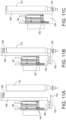
- the print head assembly 20 includes a paste cartridge mechanism including a support bracket 120 that is configured to receive, seat, seal and pressurize the paste cartridge 110 to the print head assembly 20.
- the support bracket 120 includes a base 122 having a receiving feature 124 designed to receive a bottom portion of the paste cartridge 110.
- the receiving feature 124 includes two spaced-apart prongs that are sized to surround a narrow cylindrical portion of the paste cartridge 110. The narrow cylindrical portion is disposed between two wider cylindrical portions to capture the prongs in between.
- the print head assembly 20 is configured to move to the paste cartridge 110 to secure the paste cartridge to the support bracket 120 of the paste cartridge mechanism by operating the print head assembly gantry 22.
- the support bracket 120 of the paste cartridge mechanism further includes an upright member 126 that is configured to secure, seal and pressurize an upper portion of the paste cartridge 110.
- the upright member 126 includes a sealing portion 128 that is designed to seal the upper portion of the paste cartridge 110.
- a pneumatic assembly 130 can be provided to move the base 122.
- Another pneumatic cylinder 132 can be employed to lower the entire cylinder assembly during a dispensing operation.
- the pneumatic cylinder 132 powers the up-and-down movement of the print head assembly 20 in the z-axis direction. After the paste cartridge 110 is lifted to seal against the sealing portion 128, the paste cartridge can be pressurized when required to dispense solder paste. The connection for this assembly is through the upright member 126 and the sealing portion 128.
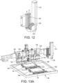
- FIG. 12 illustrates a paste cartridge 110 secured and sealed by the paste cartridge mechanism.
- the paste cartridge mechanism is capable of seating and sealing the paste cartridge 110.
- the paste cartridge mechanism can be configured to accept different sized paste cartridges or paste jars.
- each paste cartridge 110 includes a one-dimensional barcode label that wraps all the way around the paste cartridge, thereby permitting the reading of the barcode from any orientation relative to the tube.
- a support tooling movement mechanism is generally indicated at 140, which is configured to move the support tooling 78 from the tooling tray 60 to the stencil printer 10.
- the support tooling movement mechanism 140 includes a plate 142 mounted on the print head assembly 20.
- the plate 142 has four linear bearings, each indicated at 144, with a first set of linear bearings being positioned one above the other on one side of the plate and a second set of linear bearings being positioned one above the other on the other side of the plate.
- Each set of linear bearings 144 has a tooling member 146 configured to move laterally on the linear bearings. Any suitable mechanism can be employed to move the tooling member 146.
- a ball screw drive assembly can be provided to move the tooling member 146 along the linear bearings.
- the mechanism can be powered by the drive assembly that powers the up-and-down movement of the print head assembly 20 in the z-axis direction.
- Each tooling member 146 includes a downwardly extending pin 148 having a head configured to be received within a receiving feature 150 associated with the support tooling 78.
- FIG. 13A illustrates the pins 148 of the tooling members 146 being received in respective mating features 150 of the support tooling 78.
- the tooling members 146 can be extended to a width wider than the support tooling 78, and moved toward one another to capture the support tooling 78 between the pins via the receiving features 150.
- the tooling tray 60 can include recesses formed therein that are located adjacent to the support tooling 78 to enable the pins 148 to be placed laterally adjacent to the receiving features 150 of the support tooling 78.
- FIG. 13B illustrates the print head assembly 20 being raised in a z-axis direction to pick up the support tooling 78.
- the mechanism used to pick up and drop off the support tooling 78 can be configured to engage and secure the support tooling, can include magnets to facilitate attachment and detachment of the support tooling from the tooling members.
- an opening, e.g., cut out 74, is provided in the tooling tray 60 to facilitate access to the support tooling in the stencil printer 10 from the print head assembly 20 while the tooling tray is in the stencil printer.
- the arrangement is such that the movable cart 40 is configured to support a predetermined number of support tooling 78 used to support a printed circuit board 29 in a print position.
- the movable cart 40 and the stencil printer 10 operate with one another to identify the support tooling 78, store the support tooling, transport the support tooling to and from the stencil printer, inspect the support tooling, and interface with the stencil printer.
- the movable cart 40 and the stencil printer 10 also operate with one another to remove used parts, such as support tooling 78, from the stencil printer.
- multiplexing motion axes in the movable cart 40 can minimize cost and complexity of the drive system.
- the drives may reside in either the movable cart 40 or the stencil printer 10.
- the print head assembly 20 is capable of picking up and placing support tooling 78.
- the same print head assembly 20 is capable of picking up and dropping off squeegee blade assemblies 80.
- the mechanisms used to manage support tooling or plates 78, squeegee blade assemblies 80 and paste cartridges 110 can be provided on other gantries, instead of the print head assembly gantry 22, such as the imaging system gantry 32 or the stencil wiper assembly gantry.
- the movable cart 40 can be configured with an interface, which is designed to dock within a docking station provided on the stencil printer 10.
- the interface of the movable cart is configured to dock within the docking station of the stencil printer 10, both from a mechanic interface and an electronics communication interface.
- the movable cart can be configured with a unique mechanical interface that mates with a unique mechanical interface of the stencil printer 10.
- the unique mechanical interfaces can include geometric features.
- the movable cart can be configured with pins that are received within guides associated with the stencil printer 10 to register the movable cart with the stencil printer prior to fully docking the movable cart.
- the pins and guides can be reversed, with the pins provided on the stencil printer 10 and the guides provided in the movable cart.
- Other types of guides can be used, such as electrical/magnetic guides, vision guides, sensors, latches, etc.
- the movable cart when docked within the docking station of the stencil printer 10, can physically engage the stencil printer or be spaced from the stencil printer.
- movable cart can be configured to clean squeegee blades by cleaning or otherwise removing used paste from the squeegee blades.
- the movable cart can be configured to change used squeegee blades by unclamping squeegee blades from the print head 20 and positioning the used squeegee blades on an open shelf of the movable cart. New squeegee blades are taken from the movable cart and mounted on the print head 20 of the stencil printer 10.
- the movable cart includes a controller that is adapted to control the operation of the movable cart based on operational parameters obtained by the controller.
- the controller can be configured to communicate with the controller 14 of the stencil printer 10 and/or a controller associated with the production line.
- the controller may embody a plurality of controllers provided in each movable cart that communicates with one another over a controller area network (CAN) Bus or other type of network.
- CAN controller area network
- a master controller may be provided to control the operation of the controllers of the movable carts 80.
- Each movable cart may be provided with a display, which is operably coupled to the controller.
- the display is adapted to display the operational parameters of the movable cart, such as, but not limited to, the number of clean and used stencils, the number of full and spent/used paste cartridges, the number of new and used squeegee blades, and/or the number of new and used tooling. Suitable monitors may be provided to acquire such information. Alternatively, or in addition to the foregoing embodiment, the operational parameters may be displayed on the display 16 provided within the stencil printer 10 and/or a display associated with the production line.
- the movable cart may be controlled by the controller 14 of the stencil printer 10 and/or a controller associated with the production line.
- the controller can be a controller dedicated to one or more movable carts.
- material identification for items on the movable cart can include a device to manipulate the item and a scanner to scan and identify the item.
- the movable cart can be configured to include a pinch wheel to rotate the paste cartridge to align a code or predetermined identification mark provided on the paste cartridge with scanner provided on the movable cart.
- the system is configured to tie material identification associated with the paste cartridge to a recipe, production time, etc., for the stencil printer 10.
- a barcode to identify the items can be implemented.
- the barcode can include a 1D scanner for UPC codes, a 2D scanner for QRC codes, a printed label applied on the item or a laser etched label etched on the item.
- an RFID system to identify the items can be implemented.
- the RFID system can include an RFID tag applied to the item and an RFID reader associated with the movable cart 40 or the stencil printer 10. With an RFID system, line-of-site between the reader and the item is not required. Moreover, scanning is not required to identify all items within the movable cart.
- an imaging or vision system to identify the items can be implemented. The vision system could be an imaging system similar to the imaging system 30 associated with the stencil printer 10, and can be associated on the stencil printer, off the stencil printer or on the movable cart.
- a database is provided to keep track of items stocked on the movable cart.
- the database may include an open application (App) architecture and be configured to push data to the stencil printer 10.
- the movable cart 40 can be configured to communicate with the stencil printer 10 to push/pull data to stencil printer and/or the production line or configured to communicate with the production line directly.
- the database can include job information or material information.
- the database further can communicate with a manufacturing execution system (MES) associated with the production line, the stencil printer 10, or both.
- MES manufacturing execution system
- the MES system can be configured to know which materials are required for a production run.
- the movable cart can be configured to communicate with the MES system to adjust delivery of items to the stencil printer 10.
- the database further can be configured to retrieve information about items based on identification, e.g., a barcode number.
- a central management system can be provided in which the stencil printer 10 and/or the movable cart 40 is programmed to accept material coming from movable cart.
- the movable cart 40 is programmed to update the database to identify the materials on the movable cart, load information into the database associated with the movable cart and/or the stencil printer 10 from a network, which is tied back to the MES system.
- the database further can be configured to store additional information, such as usage and consumption.
- the database can be configured to store information locally or remotely, and can be configured to store data associated with one or more production runs.
- the database can be configured to obtain and store data including but not limited to traceability of stencils, paste cartridges, squeegee blades and tooling, paste usage, cycles, etc.
- the database can be configured to share prediction data when replacement/replenishment is needed.
- the database can be configured to perform one or more of the following: store information on when paste cartridges need replenishment; perform a certain function if a paste cartridge is low on paste; trigger an alarm and/or a report that the paste cartridge is low; signal to an inventory control system associated with the stencil printer 10 and/or the production line; perform analytics on consumable usage based on operating parameters and actual use and upstream/downstream equipment activity; predict changeout or maintenance (on the stencil printer and/or on the movable cart 40); and correlate over multiple sites to predict when to switch out paste cartridges.
- the database can be configured to share prediction data for other changeable/consumable items, such as for the stencils, paste cartridges, squeegee blades and tooling.
- the database can be configured to store data associated with lot traceability.
- RFID or mechanical keying of a board or a stencil frame of the stencil is provided to ensure correct alignment/orientation/direction/front-back/top-bottom when these items are inserted into the stencil printer 10. This information can be used to verify correct orientation and/or fit before the items are transported from the warehouse and/or before the items are installed in the stencil printer 10. A low-cost reader can perform this function.
- the movable cart can be configured to store materials.
- the movable cart can be configured to be flexible to accommodate where the materials come from and where the materials go to.
- the movable cart can be configured to identify where a particular material is located on the movable cart.
- the location, whether by auto delivery or manual delivery, is remote, local, on the movable cart, and/or on the stencil printer 10.
- the movable cart can be configured to control environmental parameters.
- the movable cart can be configured to control temperature for paste contained within paste cartridges by chilling stored paste cartridges, heating paste cartridges ready for use, and chilling paste cartridges that have been used, but still retain paste.
- the movable cart further can be configured to predict when to start heating/chilling paste cartridges based on upcoming production, track time for shelf life, and individually control each paste cartridge to proper temperature and at correct time.
- the movable cart can include a cartridge shooter to move paste cartridges.
- the movable cart further can be configured to control humidity to avoid condensate.
- the movable cart further can be configured to operate in a clean environment, e.g., a standard mechanical interface (SMIF) environment.
- SMIF standard mechanical interface
- the movable cart can be configured to perform inventory control. Specifically, the movable cart can be configured to identify where material is located, how much material is used, how the material is used, when the material is used, tie the material and information about the material to a customer inventory control system, and track material type consumed per board or lots of boards.
- the movable cart can be configured to organize items stored on the movable cart.
- one movable cart can be provided to store, transport and deliver multiple resources, including but not limited to stencils, paste cartridges, squeegee blades and tooling.
- the movable cart can be configured to store, transport and deliver a single resource or item to the stencil printer 10.
- the movable cart can be configured to store multiple stencils.
- the movable cart can be configured to service multiple production lines.
- the movable cart can be configured to service one stencil printer 10.
- the movable cart can be configured to transport items from the movable cart to the stencil printer 10 and from the stencil printer to the movable cart, and be able to account for elevation differences between the movable cart and the stencil printer.
- the transportation can be automated or manual.
- movable cart can be moved by automatically guided vehicle (AVG) technology associated with the movable cart or remotely controlled.
- AVG automatically guided vehicle
- the movable cart can be configured to move autonomously.
- the movable cart can be configured to be moved manually.
- the movable cart can be configured to move items stored on the movable cart automatically and/or manually.
- the movable cart can be configured to move items automatically, and can provide for an interruption of a pre-planned activity in which the items are moved manually.
- timing associated with performing transportation functions of the movable cart can be programmed to account for shift change, e.g., a personnel shift, scheduled maintenance, on demand activities, e.g., a recipe change, and predictive events (just-in-time replacements).
- the timing can be programmed to meet multiple line balance control requirements, with one or more movable carts and to meet real-time on-demand material supply demands on the production line.
- the movable cart is configured to perform inspection.
- the movable cart can inspect on cart and off cart items including stencils, paste cartridges, squeegee blades, and tooling.
- a vision system associated with the movable cart can be configured to obtain images of the items.
- the vision system in conjunction with the controller can be configured to inspect for cleanliness, damage, wear, and identification readability, e.g., is the barcode label worn, dirty or torn.
- the vision system can embody any type of 2D, 3D or color camera.
- the interface and the docking station can be configured with a clamping system to maintain the movable cart in place with respect to the stencil printer 10.
- a clamping system can be employed.
- the stencil printer 10 can be configured with multiple docking stations, e.g., five docking stations.
- the docking station can be provided at a front of the stencil printer 10 or at a back of the stencil printer.
- the movable cart and/or the stencil printer 10 can be configured to verify whether the movable cart can be docked and interface with the stencil printer. In one embodiment, verification can be provided to confirm that the movable cart is in position and ready to interface with the stencil printer 10. This verification process can further determine whether correct materials are on the movable cart and whether the movable cart material information can be received from MES system, or locally identified. If not correct, the movable cart 40 can be configured to activate an alarm and/or alert an operator if wrong or damaged materials are on the movable cart.
- the movable cart can be configured with actuation devices or actuators to move items onto and off of the movable cart once the movable cart is docked to the stencil printer 10.
- actuation devices or actuators can be implemented on the movable cart, the stencil printer 10 or both.
- the items can be manually loaded and unloaded from the movable cart.
- the movable cart can be configured to interface with a production line.
- the operator of the production line can confirm the correct location and acknowledge receipt of the movable cart on the stencil printer 10.
- the movable cart can be configured to communicate with the stencil printer 10, the production line, and/or select machines within the production line via an open platform.
- Communication systems can include a wired system, a wireless system (through a common network, mesh, Bluetooth, Wi-Fi, Zigbee, WAN, Nodes, Li-Fi, etc.), a combination of wired and wireless systems, and infrared (IR) system.
- IR infrared
- the movable cart can be configured with a dedicated power source.
- the movable cart includes a battery configured to power automated components provided in the movable cart, e.g., mechanisms used to move stencils into and out of the movable cart, mechanisms used to move paste cartridges into and out of the movable cart, mechanisms used to move squeegee blades into and out of the movable cart, and mechanisms used to move tooling into and out of the movable cart.
- the movable cart can be configured with an uninterruptible power supply.
- the power source can be configured to support actuation while "docked" (high-voltage from stencil printer when docked, otherwise low-voltage when undocked).
- the power source can be configured to recharge for autonomous operations, e.g., recharge a battery from power provided by the stencil printer 10.
- the movable cart can be configured to function with the stencil printer 10.
- the movable cart can be configured to provide a handshaking function with the stencil printer 10 prior to a transfer of an item, e.g., "please give me stencil #1234.”
- the movable cart and the stencil printer 10 can be configured with a communication protocol and/or a library reference on what is available to consume.
- the movable cart can be configured to determine whether the movable cart has correct items.
- the handshaking function can be configured to ensure the correct transfer of an item, e.g., "here's stencil #1234," and/or the subsequent transfer of an item, e.g., "I now have stencil #1234.”
- a mobile device can be configured to scan and identify items in the movable cart, and determine, for example, whether the items are ready for use, require cleaning, etc.
- the movable cart can be configured to address errors associated with handling and recovering items in the movable cart.
- the movable cart can be configured to detect an incomplete action by one party, an incomplete transfer of an item, e.g., a stuck or jammed item, a dropped transfer, e.g., "I passed stencil #1234 to you, don't you have it?," and a manual intervention or override, e.g., "here, let me help you.”
- a controller associated with the movable cart can be configured to perform static discharge control, data recovery and/or security.
- the movable cart can be configured with a higher level of capability. In addition to indexing all the equipment to the correct height, the movable cart would need to pull in/push out all equipment for stencil printer gantries to attach.
- existing stencil printer gantries, rails and print head of the stencil printer 10 can be configured to shuttle items in and out.
- the print head 20 of the stencil printer 10 can be configured to lift and shuttle a support tooling.
- the movable cart can be configured with a paste cartridge indexer at a top of the movable cart to load/unload paste cartridges.
- the movable cart can be configured to communicate with the stencil printer 10, the production line and a warehouse associated with the production line.
- the movable cart can be configured with an electrical/pneumatic interface.
- the movable cart can be configured to track consumables - new and used on the movable cart, e.g., solder paste cartridges, including location, temperature and other data.
- consumables - new and used on the movable cart e.g., solder paste cartridges, including location, temperature and other data.
- the movable cart can be configured to store and supply stencils for duration of a production run.
- the movable cart can be configured to verify and ensure that the squeegee blades are associated with a stencil to ensure compatibility of parts during a changeover.
- the squeegee blades can include disposable blades that are plastic molded blade.
- the movable cart can be configured to scan all consumables with a suitable scanning device, such as a barcode reader or RFID reader.
- a suitable scanning device such as a barcode reader or RFID reader.
- the movable cart can be configured with an indexing mechanism to properly locate consumables.
- the movable cart can be configured with a bypass switch to disconnect the movable cart from the stencil printer 10 if the movable cart has an issue.
- the movable cart can be configured to be moved manually or by an automated guided vehicle (AGV).
- AGV automated guided vehicle
- the movable cart can be configured to dock and interface with the stencil printer 10.
- the movable cart can be configured to service multiple stencil printers 10.
- the movable cart can be configured to be dedicated to one consumable item, e.g., stencils, or multiple consumable/changeover items.
- the movable cart can be configured to transport and present the consumables to be cleaned at a remote station.
- the movable cart can be configured to be refilled at a stockroom associated with a warehouse.
- the movable cart can be configured to be climate controlled, either actively or passively.
- the movable cart can be configured be controlled by an application (App) capable for smartphone integration.
- App an application capable for smartphone integration.
- an "automated” or “fully automated” changeover describes the replacement or replenishment of an item without human intervention.
- a “partially automated” changeover describes the replacement or replenishment of an item with some or limited human intervention.
- transport or “transporting” describes moving an item from one position to another, either manually or with a machine.
- install or “installing” describes the process of placing an item in a position ready for use.
- the movable cart 80 and the robotic arm 140 can be employed to replace other items within the stencil printer 10.
- the stencil wiper assembly 34 includes consumables, e.g., paper and solvent, which can be automatically replaced by the movable cart 80 and the robotic arm 140.
- the concepts disclosed herein may be employed in other types of equipment used to fabricate electronic substrates, including dispensers, pick-and-place machines, reflow ovens, wave soldering machines, selective solder machines, inspection stations, and cleaning stations.
- the concepts directed to replacing paste cartridges can be employed in dispensers used to dispense viscous material.
- the concepts directed to replacing tooling can be employed in dispensers and in pick-and-place machines used to mount electronic components onto electronic substrates.
- the concepts directed to replacing items can be employed in replacing solder within wave soldering and selective soldering machines and cleaning product within cleaning stations.
Landscapes
- Engineering & Computer Science (AREA)
- Mechanical Engineering (AREA)
- Electric Connection Of Electric Components To Printed Circuits (AREA)
- Screen Printers (AREA)
- Manufacturing Of Printed Wiring (AREA)
Description
- This application relates generally to stencil printers and related methods to print viscous materials, e.g., solder paste, on an electronic substrate, e.g., a printed circuit board (PCB), and more particularly to systems and methods for fully automating such stencil printers and methods.
- In manufacturing a surface-mount printed circuit board, a stencil printer can be used to print solder paste onto the circuit board. Typically, a circuit board having a pattern of pads or some other conductive surface onto which solder paste will be deposited is automatically fed into the stencil printer; and one or more small holes or marks (known as "fiducials") on the circuit board are used to properly align the circuit board with the stencil or screen of the stencil printer prior to printing solder paste onto the circuit board. In some systems, an optical alignment system embodying a vision system is used to align the circuit board with the stencil.
US2002019680 discloses a method for controlling a screen printer. - Once the circuit board has been properly aligned with the stencil in the printer, the circuit board is raised to the stencil, solder paste is dispensed onto the stencil, and a wiper blade (or squeegee) traverses the stencil to force the solder paste through apertures in the stencil and onto the circuit board. As the squeegee is moved across the stencil, the solder paste tends to roll in front of the blade, which desirably causes mixing and shearing of the solder paste so as to attain a desired viscosity to facilitate filling of the apertures in the screen or stencil. The solder paste typically is dispensed onto the stencil from a standard cartridge. The stencil is then separated from the circuit board and the adhesion between the circuit board and the solder paste causes most of the material to stay on the circuit board. Material left on the surface of the stencil is removed in a cleaning process before additional circuit boards are printed.
- Another process in the printing of circuit boards involves inspection of the circuit boards after solder paste has been deposited on the surface of the circuit boards. Inspecting the circuit boards is important for determining that clean electrical connections can be made. An excess of solder paste can lead to shorts, while too little solder paste in appropriate positions can prevent electrical contact. Generally, the vision inspection system is further employed to provide a two-dimensional or a three-dimensional inspection of the solder paste on the circuit board.
- Present day stencil printers require manual intervention to perform routine operations. For example, during a changeover, an operator must perform many manual tasks, such as changing a stencil, replacing a solder paste cartridge, replacing squeegee blades, and replacing support tooling. Each of these tasks require the operator to manually perform the task. For example, with most stencil printers, the operator must unlock the stencil, remove the stencil, properly insert a replacement stencil, and lock the replacement stencil in place. A changeover operation can take as long as 30 minutes, during which the stencil printer is not operating, which may result in the PCB fabrication line not operating.
- Stencil printers further require manual intervention to perform replacement and/or replenishment operations. For example, solder paste cartridges, which supply temperature-controlled solder paste to the stencil printer, require replacement over time, e.g., within four hours or less. Items subject to normal wear and tear, such as squeegee blades and stencils, may require periodic replacement when damaged.
- The application is defined by the independent claims 1 and 13. Preferred embodiments are disclosed in the coresponding description pages.
- The accompanying drawings are not intended to be drawn to scale. In the drawings, each identical or nearly identical component that is illustrated in various figures is represented by a like numeral. For purposes of clarity, not every component may be labeled in every drawing. In the drawings:
-
FIG. 1 is a front perspective view of a stencil printer; -
FIG. 2 is a front view of a stencil printer; -
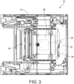
FIG. 3 is a top plan view of the stencil printer illustrated inFIG. 2 with portions removed; -
FIG. 4 is a perspective view of a removable cart of an embodiment of the disclosure, with external packaging removed to reveal interior structure of the movable cart; -
FIG. 5A is a perspective view of a tooling tray of an embodiment of the disclosure; -
FIG. 5B is a perspective view of the tooling tray supporting tooling and squeegee blade assemblies; -
FIG. 6 is a perspective view of a tooling tray of another embodiment of the disclosure; -
FIGS. 7A and7B are cross-sectional views of a portion of an end effector of a print head assembly and a portion of a squeegee blade holder of a squeegee blade assembly in disengaged and engaged positions, respectively; -
FIG. 7C is a cross-sectional view of the end effector and the squeegee blade holder in the engaged position; -
FIGS. 8A and 8B are cross-sectional views of a release mechanism configured to release the end effector from the squeegee blade holder; -
FIGS. 9A and 9B are perspective views of a magazine configured to support paste cartridges in retracted and extended positions, respectively. -
FIG. 10 is a perspective view of the paste cartridges; -
FIGS. 11A-11C are sequential views illustrating the installation of a paste cartridge on the print head assembly; -
FIG. 12 is a perspective view of the paste cartridge provided in a paste cartridge mechanism; and -
FIGS. 13A-13C are perspective views of the print head assembly configured to remove tooling from the tooling tray. - The present disclosure relates generally to material application machines (referred to herein as "stencil printers," "screen printers," "printing machines," or "printers") and other equipment utilized in a surface mount technology (SMT) process lines and configured to apply an assembly material (e.g., solder paste, conductive ink, or encapsulation material) onto a substrate (e.g., a printed circuit board, referred to herein as an "electronic substrate," a "circuit board," a "board," a "PCB," a "PCB substrate," a "substrate," or a "PCB board") or to perform other operations, such as inspection, rework, or placement of electronic components onto a substrate. Specifically, embodiments of the present disclosure are described below with reference to stencil printers used to produce printed circuit boards.
- For the purposes of illustration only, and not to limit the generality, the present disclosure will now be described in detail with reference to the accompanying figures. This disclosure is not limited in its application to the details of construction and the arrangement of components set forth in the following description or illustrated in the drawings. The principles set forth in this disclosure are capable of other embodiments and of being practiced or carried out in various ways. Also, the phraseology and terminology used herein is for the purpose of description and should not be regarded as limiting. Any references to examples, embodiments, components, elements or acts of the systems and methods herein referred to in the singular may also embrace embodiments including a plurality, and any references in plural to any embodiment, component, element or act herein may also embrace embodiments including only a singularity. References in the singular or plural form are not intended to limit the presently disclosed systems or methods, their components, acts, or elements. The use herein of "including," "comprising," "having," "containing," "involving," and variations thereof is meant to encompass the items listed thereafter as well as additional items. References to "or" may be construed as inclusive so that any terms described using "or" may indicate any of a single, more than one, and all of the described terms.
- For purposes of illustration, embodiments of the present disclosure will now be described with reference to a stencil printer used to print an assembly material, such as solder paste, onto a circuit board. One skilled in the art will appreciate, however, that embodiments of the present disclosure are not limited to stencil printers that print solder paste onto circuit boards, but rather, may be used in other applications requiring dispensing of other viscous assembly materials, such as glues and encapsulents. For example, the apparatus may be used to print epoxy for use as underfill for chip-scale packages. Further, stencil printers in accordance with embodiments of the present disclosure are not limited to those that print assembly materials on circuit boards, but rather, include those used for printing other materials on a variety of substrates, such as semiconductor wafers. Also, the terms screen and stencil may be used interchangeably herein to describe a device in a printer that defines a pattern to be printed onto a substrate. In certain embodiments, the stencil printer may include a Momentum® or an Edison™ series stencil printer platform offered by ITW Electronic Assembly Equipment of Hopkinton, Massachusetts. An exemplary stencil printer is generally designated at 5 in
FIG. 1 . In this embodiment, thestencil printer 5 is a Momentum® series stencil printer platform offered by ITW Electronic Assembly Equipment of Hopkinton, Massachusetts. - Referring to
FIG. 2 , there is generally indicated at 10 a stencil printer of an embodiment of the disclosure. As shown, thestencil printer 10 includes aframe 12 that supports components of the stencil printer. The components of the stencil printer may include, in part, acontroller 14, adisplay 16, astencil 18, and a print head or print head assembly, generally indicated at 20, which is configured to apply the solder paste in a manner described in greater detail below. - As shown in
FIG. 2 and described below, the stencil and the print head assembly may be suitably coupled or otherwise connected to theframe 12. In one embodiment, theprint head assembly 20 may be mounted on a printhead assembly gantry 22, which may be mounted on theframe 12. The printhead assembly gantry 22 enables theprint head assembly 20 to be moved in the y-axis direction under the control of thecontroller 14 and to apply pressure on the print head assembly as it engages thestencil 18. In a certain embodiment, theprint head assembly 20 may be placed over thestencil 18 and may be lowered in the z-axis direction into contact and sealingly engage the stencil. - The
stencil printer 10 may also include a conveyor system having rails (not shown) for transporting a printed circuit board (sometimes referred to as a "printed wiring board," "substrate," or "electronic substrate" herein) to a print position in the stencil printer. The rails sometimes may be referred to herein as a "tractor feed mechanism," which is configured to feed, load or otherwise deliver circuit boards to the working area of the stencil printer, which may be referred to herein as a "print nest," and to unload circuit boards from the print nest. - Referring additionally to
FIG. 3 , thestencil printer 10 has asupport assembly 28 to support the circuit board 29 (shown in dashed lines), which raises and secures the circuit board so that it is stable during a print operation. In certain embodiments, thesubstrate support assembly 28 further may include a particular substrate support system, e.g., a solid support, a plurality of pins or flexible tooling, which is positioned beneath the circuit board when the circuit board is in the print position. The substrate support system may be used, in part, to support the interior regions of the circuit board to prevent flexing or warping of the circuit board during the print operation. - In one embodiment, the
print head assembly 20 may be configured to receive solder paste from a source, such as a dispenser, e.g., a solder paste cartridge, that provides solder paste to the print head assembly during the print operation. Other methods of supplying solder paste may be employed in place of the cartridge. For example, solder paste may be manually deposited between the blades or from an external source. Additionally, in a certain embodiment, thecontroller 14 may be configured to use a personal computer having a suitable operating system, such as a Microsoft Windows® operating system provided by Microsoft Corporation, with application specific software to control the operation of thestencil printer 10. Thecontroller 14 may be networked with a master controller that is used to control a production line for fabricating circuit boards. - In one configuration, the
stencil printer 10 operates as follows. Acircuit board 29 is loaded into thestencil printer 10 using the conveyor rails. Thesupport assembly 28 raises and secures thecircuit board 29 to a print position. Theprint head assembly 20 is then lowered in the z-axis direction until blades of the print head assembly contact thestencil 18 at a desired pressure. Theprint head assembly 20 is then moved in the y-axis direction across thestencil 18 by the printhead assembly gantry 22. Theprint head assembly 20 deposits solder paste through apertures in thestencil 18 and onto thecircuit board 29. Once the print head assembly has fully traversed thestencil 18 across the apertures, the print head assembly is lifted off the stencil and thecircuit board 29 is lowered back onto the conveyor rails. Thecircuit board 29 is released and transported from thestencil printer 10 so that a second circuit board may be loaded into the stencil printer. To print on thesecond circuit board 29, the print head assembly is lowered in the z-axis direction into contact with the stencil and moved across thestencil 18 in the direction opposite to that used for the first circuit board. - An
imaging system 30 may be provided for the purposes of aligning thestencil 18 with thecircuit board 29 prior to printing and to inspect the circuit board after printing. In one embodiment, theimaging system 30 may be disposed between thestencil 18 and thesupport assembly 28 upon which a circuit board is supported. Theimaging system 30 is coupled to animaging gantry 32 to move the imaging system. In one embodiment, theimaging gantry 32 may be coupled to theframe 12, and includes a beam that extends between side rails of theframe 12 to provide back and forth movement of theimaging system 30 over thecircuit board 29 in a y-axis direction. Theimaging gantry 32 further may include a carriage device, which houses theimaging system 30, and is configured to move along the length of the beam in an x-axis direction. The construction of theimaging gantry 32 used to move theimaging system 30 is well known in the art of solder paste printing. The arrangement is such that theimaging system 30 may be located at any position below thestencil 18 and above thecircuit board 29 to capture an image of predefined areas of the circuit board or the stencil, respectively. - After one or more applications of the solder paste to circuit boards, excess solder paste may accumulate at the bottom of the
stencil 18 and a stencil wiper assembly, generally indicated at 34, and may move beneath the stencil to remove the excess solder paste. In other embodiments, thestencil 18 may be moved over the stencil wiper assembly. - As mentioned above, stencil printers require manual intervention to perform replacement of certain parts and/or replenishment operations. For example, a typical stencil requires replacement after a certain period of time, e.g., four hours. Also, stencils need replacement for separate production runs. In addition, solder paste cartridges, which supply temperature-controlled solder paste to the stencil printer, require replacement over time, e.g., within four hours or less. A separate production run may require a different solder paste material. Another item requiring periodic replacement is squeegee blades, which are subject to wearing during use. And finally, tooling used to support a substrate in a print position is subject to replacement when changing from one production product to another.
- A system and method of replacing tooling used to support a substrate in a print position includes, either for a new production run or because of a defect detected with existing tooling, retrieving new tooling from a tooling stockroom and transported to one of several stencil printers. At the production line, the used tooling is removed from the stencil printer and the new tooling is inserted into the stencil printer and secured for use. The used tooling is transported to a station where the tooling is inspected, and if salvageable, cleaned for reuse. If defective, the tooling is scrapped in a responsible manner. Once cleaned, the tooling is transported back to the tooling stockroom, where the tooling is ready to be used during the same or different production run.
- A system and method of replacing a squeegee blade or a pair of squeegee blades includes, either for a new production run or because of a defect detected with an existing squeegee blade, retrieving a new squeegee blade from a squeegee blade stockroom and transporting the new squeegee blade to one of several stencil printers. At the production line, the used squeegee blade is removed from the stencil printer and the new squeegee blade is inserted into the stencil printer and secured for use. The used squeegee blade is transported to a station where the squeegee blade is inspected, and if salvageable, cleaned for reuse. If defective, the squeegee blade is scrapped in a responsible manner. Once cleaned, the squeegee blade is transported back to the squeegee blade stockroom, where the squeegee blade is ready to be used during the same or different production run.
- A system and method of replacing a paste cartridge, either for a new production run or because of exhaustion of an existing paste cartridge, includes retrieving a new paste cartridge from a paste cartridge stockroom and transporting the new paste cartridge to one of several stencil printers. The stencil printers can be part of a single production line used to fabricate printed circuit boards or part of several production lines. The number of stencil printers can vary. The storage of the paste cartridges in the stockroom and the transportation of the paste cartridge should take place in a temperature- and/or climate-controlled environment suitable to preserve the solder paste contained within the solder paste cartridges. At the production line, the "spent" or used paste cartridge is removed from the stencil printer and the "full" or new paste cartridge is inserted into the stencil printer and secured for use. The spent paste cartridge is transported to a station where the paste cartridge is saved (because it is not completely used) or saved for recycling. Once saved or recycled, the paste cartridge is transported back to the paste cartridge stockroom, where the paste cartridge is ready to be used during the same or different production run.
- Embodiments of the present disclosure are directed to a delivery system that is configured to automate a changeover process for a stencil printer and to implement one or more of the systems and methods described herein. In one embodiment, the delivery system includes a movable cart that is configured to engage a stencil printer to supply and receive replacement and replenishment parts and materials to the stencil printer. For example, the stencil printer may include a docking station that is configured to receive the movable cart. The docking station may include an interface that enables the movable cart to communicate with the stencil printer. A single movable cart may be configured to include replacement support tooling, replacement squeegee blades, replenishment squeegee blades, replacement solder paste cartridges, and replenishment solder paste cartridges. During a changeover, for example, the stencil printer must be reconfigured to produce different items. Thus, a new support tool to accommodate a different substrate, a new blades having different lengths, and a different type of solder paste may be employed within the stencil printer to produce a different product.
- The changeover process described herein can be achieved by a single movable cart that is configured to replace and/or replenish each item. In other embodiments, more than one movable cart can be provided.
- The movable cart, or another movable cart, is configured to support a predetermined number of tooling used to support a printed circuit board in a print position, which is selected for production runs anticipated for a particular day or a particular period of time. The movable cart and/or the stencil printer can be configured to identify the support tooling, store the support tooling, transport the support tooling to and from the stencil printer, inspect the support tooling, and interface with the stencil printer. The movable cart also may be configured to remove used parts, such as support tooling, from the stencil printer.
- The movable cart, or another movable cart, is configured to support a predetermined number of squeegee blades, which are selected for production runs anticipated for a particular day or a particular period of time. The movable cart and/or the stencil printer can be configured to identify the squeegee blades, store the squeegee blades, transport the squeegee blades to and from the stencil printer, inspect the squeegee blades, and interface with the stencil printer. The movable cart also may be configured to remove used parts, such as squeegee blades, from the stencil printer.
- The movable cart, or another movable cart, is configured to support a predetermined number of paste cartridges, which are selected for production runs anticipated for a particular day or a particular period of time. The movable cart and/or the stencil printer can be configured to identify the paste cartridges, store the paste cartridges in a suitable environment, transport the paste cartridges to and from the stencil printer, inspect the paste cartridges, and interface with the stencil printer. The movable cart also may be configured to remove used parts, such as paste cartridges, from the stencil printer. Moreover, the movable cart can be configured to store paste cartridges long term. In one embodiment, long term storage of solder paste can be achieved by refrigeration at 0 to 10 °C (32 to 50 °F). The paste cartridges can be stored at a location in the movable cart to maintain this temperature range. In another embodiment, the movable cart can be configured to pre-heat the paste cartridges prior to use to ready the cartridges for use in the stencil printer.
- Referring to
FIG. 4 , in one embodiment, a movable cart, generally indicated at 40, includes a frame orhousing 42 configured to support replacement and/or replenishment items. As shown, theframe 42 is generally rectangular and is supported on wheels or casters (not shown). In one embodiment, themovable cart 40 is configured to be manually moved by an operator by pushing theframe 42 of the movable cart. In this embodiment, themovable cart 40 can be configured with a push bar or a handle. In another embodiment, themovable cart 40 is configured to be automatically moved, either by remote control or by an automated control associated with the movable cart, thestencil printer 10, the production line, and/or some other dedicated control. In this embodiment, themovable cart 40 can include wheels that are driven by a suitable motor and drive train, and a control associated with the movable cart, thestencil printer 10, the production line, and/or some other dedicated control is configured to control the movable cart. Themovable cart 40 further can include one or more sensors and/or a vision system, e.g., cameras, to guide the movable cart from a stockroom, for example, to the stencil printer. - The
movable cart 40 includes a translatable carriage, generally indicated at 44, that can be configured to support one or more items, such as replacement stencils, replacement support tooling, replacement and/or replenishment squeegee blades, and replacement and/or replenishment paste cartridges. Thetranslatable carriage 44 includes arectangular structure 46 having a top 48, a bottom 50,opposite sides sides structure 46 can includes slots, each indicated at 56, each slot being configured to receive and support opposite edges of a planar item, such as thestencil 18, or, in the shown embodiment, a tooling tray, generally indicated at 60. Thestructure 46 can be configured to receive several items, e.g., ten or more. The space betweenslots 56 can be sized to receive a standard stencil frame therein. - The
translatable carriage 44 further includes four vertically oriented rods, each indicated at 62, positioned at the four corners of thestructure 46. As shown, the top of thestructure 46 includes twobar members bar member 64 being secured to the top 48 of the structure adjacent the open front of the structure and theother bar member 66 being secured to the top adjacent the open back. Similarly, the bottom of thestructure 46 includes twobar members bar member 64a being secured to the bottom 50 of the structure adjacent the open front of the structure and theother bar member 66a being secured to the bottom adjacent the open back. Eachbar member structure 46 is capable of moving vertically with respect to therods 62 to raise and lower the structure. A suitable mechanism can be provided to raise and lower thestructure 46 under the control of a controller. For example, a ball screw drive assembly can be provided to move thestructure 46 to position a "shelf' defined by aslot 56 adjacent thestencil printer 10. The "shelves" can be specifically designed to support thetooling tray 60, which can be configured to support items including, but not limited to new and used support tooling, new and used squeegee blades, and new and spent/used paste cartridges. Some shelves can includetooling trays 60 that are designated as "clean shelves" to support clean or new items ready to be used within thestencil printer 10. Some shelves can includetooling trays 60 that are designated as "dirty shelves" to support used items to be taken away from thestencil printer 10. As mentioned above, the space between theslots 56 can be spaced apart from one another specific distances to receive various items. For example, the shelves can be spaced apart 3/8-inch to 1½-inch from one another to accommodate stencil frame and tooling tray thicknesses. - The
movable cart 40 can be configured with one or more devices used to transport items from the movable cart to thestencil printer 10 and from the stencil printer to the movable cart. For example, the device can include atransport arm 68 that is configured to push and retrievestencils 18 andtooling trays 60 to and from themovable cart 40, respectively. For example, as shown inFIG. 4 , thetransport arm 68 is pushing thetooling tray 60 away from themovable cart 40, with the tooling tray being positioned to be received by the stencil printer. Any suitable mechanism can be provided to move the transport arm, such as a ball screw drive assembly. - Referring to
FIGS. 5A and 5B , thetooling tray 60 includes a rectangular orsquare frame 70 and aplanar body 72. Theframe 70 can be sized to replicate the frame of thestencil 18. In one embodiment, thetooling tray 60 can be fabricated from lightweight yet strong material, such as an aluminum alloy. As shown inFIG. 5A , thebody 72 of thetooling tray 60 can include several cut outs, each indicated at 74, and several recesses, each indicated at 76, to receive support tooling and squeegee blade assemblies, respectively. As shown inFIG. 5B , thecut outs 74 are configured to receive and secure support tooling, each indicated at 78, which is provided to support theelectronic substrate 29 during a stencil print operation. Therecesses 76 are configured to receive and secure squeegee blade assemblies, each indicated at 80, which are used by theprint head assembly 20 to perform a stencil print operation. - As noted, the
tooling tray 60 is substantially the same in form-factor as a stencil to permit handling and storage/retrieval of the tooling tray in substantially the same manner as a stencil. Themovable cart 40 and thetooling tray 60 are particularly suited to handle stencils and tooling trays in a common manner. Themovable cart 40 is configured to partially deliver thetooling tray 60 from the movable cart to thestencil printer 10, and the stencil printer is configured to receive the tooling tray the rest of the way. For example, thetransport arm 68 can be used to push thetooling tray 60 away from thecarriage 44 and to retrieve the tooling tray into the carriage. - In some embodiments, the
tooling tray 60 can include fiducials, which can be viewed by theimaging system 30 of thestencil printer 10 to establish alignment to the parts and locations on the tooling tray. A method of aligning to thetooling tray 60 can be employed by capturing and analyzing fiducial locations. - Referring to
FIG. 6 , theprint head assembly 20 of thestencil printer 10 includes anend effector 82, which can be configured to pick up and release items from thetooling tray 60. As previously described, theprint head assembly 20 is mounted on the printhead assembly gantry 22, which moves the print head assembly in the y-axis direction under the control of thecontroller 14. Theprint head assembly 22 is configured to move in the z-axis direction as described above. - In one embodiment, the
end effector 82 can be configured to pick up and release asqueegee blade assembly 80. Theend effector 82 is configured to toolessly engage and disengage thesqueegee blade assembly 80 to attach and remove the squeegee blade assembly from theprint head assembly 20. As shown, thetooling tray 60 is configured with a spring-loaded locking mechanism to secure a squeegee blade holder of thesqueegee blade assembly 80 to theend effector 82 of theprint head assembly 20. A method of passively picking up and dropping offsqueegee blade assemblies 80 without needing additional axes or actuators can be performed by theend effector 82. - Referring to
FIGS. 7A-7C , theend effector 82 includes a rectangularly-shapedbody 84 that is secured to theprint head assembly 20 by a pair of connecting rods, each indicated at 86. Theend effector 82 further includes a pair of downwardly extending pins (FIG. 7C ), each indicated at 88, with each pin having anotch 90, the purpose of which will be described as the description of the mechanism proceeds. Thesqueegee blade assembly 80 includes aholder 92 having an L-shapedrecess 94 formed therein. Therecess 94 includes avertical portion 94a and ahorizontal portion 94b. The mechanism includes a spring-loadedpin 96 that is housed within thehorizontal portion 94b of therecess 94, which is biased toward thevertical portion 94a of the recess by aspring 98. -
FIGS. 7A and7B illustrate thepin 88 of theend effector 82 entering thevertical portion 94a of therecess 94. As thepin 88 enters thevertical portion 94a of therecess 94, a sloped portion of the pin engages a corresponding sloped portion of the spring-loadedpin 96. The downward movement of thepin 88 causes the spring-loadedpin 96 to move against the bias of thespring 98 until thenotch 90 of the pin receives anengaging element 100 of the spring-loaded pin to engage and secure theholder 92 of thesqueegee blade assembly 80 to theend effector 82.FIG. 7C illustrates bothpins 88 being secured by their respective spring-loadedpins 96 to secure theholder 92 of thesqueegee blade assembly 80. In this position, theend effector 82 secures thesqueegee blade assembly 80 in which the squeegee blade assembly can be employed to perform a stencil print operation. -
FIGS. 8A and 8B illustrate thepin 88 of theend effector 82 being retracted from thevertical portion 94a of therecess 94. An upwardly projectingelement 102 is provided on thetooling tray 60 to move the spring-loadedpin 96 from the engaged position illustrated inFIGS. 7B and 7C to the disengaged position illustrated inFIG. 7A . Referring toFIG. 8A , a sloped portion of theelement 102 engages a corresponding sloped portion formed on the spring-loadedpin 96. The downward movement of theend effector 82 toward theelement 102 causes the spring-loadedpin 96 to move against the bias of thespring 98 until theengaging element 100 of the spring-loaded pin is removed from thenotch 90 of thepin 88 to release thesqueegee blade assembly 80 from theend effector 82, which is shown inFIG 8B . Theelement 102 maintains the spring-loadedpin 96 in the disengaged position thereby enabling the release of theholder 92 of thesqueegee blade assembly 80. - In some embodiments, the
end effector 82 can employ magnets to engage magnetic material associated with thesqueegee blade assembly 80 to secure and release the squeegee blade assembly to theprint head assembly 20. - Referring back to
FIG. 4 , themovable cart 40 includes replacement paste cartridges, each indicated at 110. As shown, thepaste cartridges 110 are supported on a paste cartridge staging area of themovable cart 40, otherwise referred to as an "on-deck-circle," which permits thestencil printer 10 to be continuously fed solder paste for uninterrupted operation. Referring toFIGS. 9A and 9B , theframe 12 of thestencil printer 10 includes ablock 114 having recesses configured to support thepaste cartridges 110 in an upright, vertical positions when receiving paste cartridges from themovable cart 40. Theblock 114 is secured to amovable support arm 116, which is coupled to theframe 12 of thestencil printer 10 and configured to move from a retracted position to an extended position. Eachpaste cartridge 110 is supported by a cylindrical half-wall 118 to provide lateral support to the paste cartridge to assist in maintaining the paste cartridge in a vertical position. Theblock 114 shown inFIGS. 9A and 9B is configured to support twopaste cartridges 110, although the block may be configured to support any number of paste cartridges. -
FIG. 9A illustrates theblock 114 and themovable support arm 116 in the retracted position where thestencil printer 10 stores thepaste cartridges 110.FIG. 9B illustrates theblock 114 and themovable support arm 116 in the extended position in whichpaste cartridges 110 can be transferred from themovable cart 40 to the block. Any suitable mechanism can be provided to move themovable support arm 116, such as a ball screw drive assembly. - In some embodiments, the
paste cartridges 110 can be hand fed manually onto theblock 114 of thestencil printer 10 without the movable cart. - Referring to
FIG. 10 ,multiple paste cartridges 110 can be provided in amagazine 112 of "N" paste cartridges that permits operation of thestencil printer 10, including paste change-over(s), even when themovable cart 40 is not present. The number ofpaste cartridges 110 provided by themagazine 112 can be determined by the logistic needs of thestencil printer 10 and the particular application. - Referring to
FIGS. 11A-11C , the process of installing thepaste cartridge 110 on theprint head assembly 20 is sequentially illustrated. Theprint head assembly 20 includes a paste cartridge mechanism including asupport bracket 120 that is configured to receive, seat, seal and pressurize thepaste cartridge 110 to theprint head assembly 20. As shown, thesupport bracket 120 includes a base 122 having a receivingfeature 124 designed to receive a bottom portion of thepaste cartridge 110. In the shown example, the receivingfeature 124 includes two spaced-apart prongs that are sized to surround a narrow cylindrical portion of thepaste cartridge 110. The narrow cylindrical portion is disposed between two wider cylindrical portions to capture the prongs in between. Theprint head assembly 20 is configured to move to thepaste cartridge 110 to secure the paste cartridge to thesupport bracket 120 of the paste cartridge mechanism by operating the printhead assembly gantry 22. - The
support bracket 120 of the paste cartridge mechanism further includes anupright member 126 that is configured to secure, seal and pressurize an upper portion of thepaste cartridge 110. Theupright member 126 includes a sealingportion 128 that is designed to seal the upper portion of thepaste cartridge 110. Once thepaste cartridge 110 is seated in the receivingfeature 124 of thebase 122, the base is configured to move upwardly in the manner shown betweenFIGS. 11B and 11C to seal a pneumatic pressure connection of thepaste cartridge 110 with the sealingportion 128. Once pressurized, thepaste cartridge 110 is ready to perform a dispensing operation. Any suitable mechanism can be employed to move the base 122 in an upward direction and in a downward direction to engage and disengage thepaste cartridge 110 to and from the sealingportion 128, respectively. For example, apneumatic assembly 130 can be provided to move thebase 122. Anotherpneumatic cylinder 132 can be employed to lower the entire cylinder assembly during a dispensing operation. In one embodiment, thepneumatic cylinder 132 powers the up-and-down movement of theprint head assembly 20 in the z-axis direction. After thepaste cartridge 110 is lifted to seal against the sealingportion 128, the paste cartridge can be pressurized when required to dispense solder paste. The connection for this assembly is through theupright member 126 and the sealingportion 128. -
FIG. 12 illustrates apaste cartridge 110 secured and sealed by the paste cartridge mechanism. Thus, the paste cartridge mechanism is capable of seating and sealing thepaste cartridge 110. The paste cartridge mechanism can be configured to accept different sized paste cartridges or paste jars. - In some embodiments, each
paste cartridge 110 includes a one-dimensional barcode label that wraps all the way around the paste cartridge, thereby permitting the reading of the barcode from any orientation relative to the tube. - Referring to
FIGS. 13A-13C , a support tooling movement mechanism is generally indicated at 140, which is configured to move thesupport tooling 78 from thetooling tray 60 to thestencil printer 10. As shown, the supporttooling movement mechanism 140 includes aplate 142 mounted on theprint head assembly 20. Theplate 142 has four linear bearings, each indicated at 144, with a first set of linear bearings being positioned one above the other on one side of the plate and a second set of linear bearings being positioned one above the other on the other side of the plate. Each set oflinear bearings 144 has atooling member 146 configured to move laterally on the linear bearings. Any suitable mechanism can be employed to move thetooling member 146. For example, a ball screw drive assembly can be provided to move thetooling member 146 along the linear bearings. In one embodiment, the mechanism can be powered by the drive assembly that powers the up-and-down movement of theprint head assembly 20 in the z-axis direction. Eachtooling member 146 includes a downwardly extendingpin 148 having a head configured to be received within a receivingfeature 150 associated with thesupport tooling 78. -
FIG. 13A illustrates thepins 148 of thetooling members 146 being received in respective mating features 150 of thesupport tooling 78. Thetooling members 146 can be extended to a width wider than thesupport tooling 78, and moved toward one another to capture thesupport tooling 78 between the pins via the receiving features 150. Thetooling tray 60 can include recesses formed therein that are located adjacent to thesupport tooling 78 to enable thepins 148 to be placed laterally adjacent to the receiving features 150 of thesupport tooling 78.FIG. 13B illustrates theprint head assembly 20 being raised in a z-axis direction to pick up thesupport tooling 78. The mechanism used to pick up and drop off thesupport tooling 78 can be configured to engage and secure the support tooling, can include magnets to facilitate attachment and detachment of the support tooling from the tooling members. As shown, an opening, e.g., cut out 74, is provided in thetooling tray 60 to facilitate access to the support tooling in thestencil printer 10 from theprint head assembly 20 while the tooling tray is in the stencil printer. - The arrangement is such that the
movable cart 40 is configured to support a predetermined number ofsupport tooling 78 used to support a printedcircuit board 29 in a print position. Themovable cart 40 and thestencil printer 10 operate with one another to identify thesupport tooling 78, store the support tooling, transport the support tooling to and from the stencil printer, inspect the support tooling, and interface with the stencil printer. Themovable cart 40 and thestencil printer 10 also operate with one another to remove used parts, such assupport tooling 78, from the stencil printer. - In some embodiments, multiplexing motion axes in the
movable cart 40 can minimize cost and complexity of the drive system. The drives may reside in either themovable cart 40 or thestencil printer 10. - In some embodiments, the
print head assembly 20 is capable of picking up and placingsupport tooling 78. The sameprint head assembly 20 is capable of picking up and dropping offsqueegee blade assemblies 80. - In some embodiments, the mechanisms used to manage support tooling or
plates 78,squeegee blade assemblies 80 andpaste cartridges 110 can be provided on other gantries, instead of the printhead assembly gantry 22, such as theimaging system gantry 32 or the stencil wiper assembly gantry. - The
movable cart 40 can be configured with an interface, which is designed to dock within a docking station provided on thestencil printer 10. In one embodiment, the interface of the movable cart is configured to dock within the docking station of thestencil printer 10, both from a mechanic interface and an electronics communication interface. In a particular embodiment, the movable cart can be configured with a unique mechanical interface that mates with a unique mechanical interface of thestencil printer 10. The unique mechanical interfaces can include geometric features. In another embodiment, the movable cart can be configured with pins that are received within guides associated with thestencil printer 10 to register the movable cart with the stencil printer prior to fully docking the movable cart. The pins and guides can be reversed, with the pins provided on thestencil printer 10 and the guides provided in the movable cart. Other types of guides can be used, such as electrical/magnetic guides, vision guides, sensors, latches, etc. The movable cart, when docked within the docking station of thestencil printer 10, can physically engage the stencil printer or be spaced from the stencil printer. - In some embodiments, movable cart can be configured to clean squeegee blades by cleaning or otherwise removing used paste from the squeegee blades.
- In some embodiments, the movable cart can be configured to change used squeegee blades by unclamping squeegee blades from the
print head 20 and positioning the used squeegee blades on an open shelf of the movable cart. New squeegee blades are taken from the movable cart and mounted on theprint head 20 of thestencil printer 10. - In some embodiments, the movable cart includes a controller that is adapted to control the operation of the movable cart based on operational parameters obtained by the controller. The controller can be configured to communicate with the
controller 14 of thestencil printer 10 and/or a controller associated with the production line. In one embodiment having multiple movable carts, the controller may embody a plurality of controllers provided in each movable cart that communicates with one another over a controller area network (CAN) Bus or other type of network. In other embodiments, a master controller may be provided to control the operation of the controllers of themovable carts 80. Each movable cart may be provided with a display, which is operably coupled to the controller. The display is adapted to display the operational parameters of the movable cart, such as, but not limited to, the number of clean and used stencils, the number of full and spent/used paste cartridges, the number of new and used squeegee blades, and/or the number of new and used tooling. Suitable monitors may be provided to acquire such information. Alternatively, or in addition to the foregoing embodiment, the operational parameters may be displayed on thedisplay 16 provided within thestencil printer 10 and/or a display associated with the production line. - In other embodiments, the movable cart may be controlled by the
controller 14 of thestencil printer 10 and/or a controller associated with the production line. The controller can be a controller dedicated to one or more movable carts. - In some embodiments, material identification for items on the movable cart can include a device to manipulate the item and a scanner to scan and identify the item. For example, for paste cartridges, the movable cart can be configured to include a pinch wheel to rotate the paste cartridge to align a code or predetermined identification mark provided on the paste cartridge with scanner provided on the movable cart. The system is configured to tie material identification associated with the paste cartridge to a recipe, production time, etc., for the
stencil printer 10. In one embodiment, a barcode to identify the items can be implemented. For example, the barcode can include a 1D scanner for UPC codes, a 2D scanner for QRC codes, a printed label applied on the item or a laser etched label etched on the item. In another embodiment, an RFID system to identify the items can be implemented. For example, the RFID system can include an RFID tag applied to the item and an RFID reader associated with themovable cart 40 or thestencil printer 10. With an RFID system, line-of-site between the reader and the item is not required. Moreover, scanning is not required to identify all items within the movable cart. In another embodiment, an imaging or vision system to identify the items can be implemented. The vision system could be an imaging system similar to theimaging system 30 associated with thestencil printer 10, and can be associated on the stencil printer, off the stencil printer or on the movable cart. - In some embodiments, a database is provided to keep track of items stocked on the movable cart. In one embodiment, the database may include an open application (App) architecture and be configured to push data to the
stencil printer 10. Themovable cart 40 can be configured to communicate with thestencil printer 10 to push/pull data to stencil printer and/or the production line or configured to communicate with the production line directly. The database can include job information or material information. The database further can communicate with a manufacturing execution system (MES) associated with the production line, thestencil printer 10, or both. The MES system can be configured to know which materials are required for a production run. The movable cart can be configured to communicate with the MES system to adjust delivery of items to thestencil printer 10. - The database further can be configured to retrieve information about items based on identification, e.g., a barcode number. In one embodiment, a central management system can be provided in which the
stencil printer 10 and/or themovable cart 40 is programmed to accept material coming from movable cart. Themovable cart 40 is programmed to update the database to identify the materials on the movable cart, load information into the database associated with the movable cart and/or thestencil printer 10 from a network, which is tied back to the MES system. - The database further can be configured to store additional information, such as usage and consumption. The database can be configured to store information locally or remotely, and can be configured to store data associated with one or more production runs. For example, the database can be configured to obtain and store data including but not limited to traceability of stencils, paste cartridges, squeegee blades and tooling, paste usage, cycles, etc.
- The database can be configured to share prediction data when replacement/replenishment is needed. For example, with respect to storing information related to paste cartridges, the database can be configured to perform one or more of the following: store information on when paste cartridges need replenishment; perform a certain function if a paste cartridge is low on paste; trigger an alarm and/or a report that the paste cartridge is low; signal to an inventory control system associated with the
stencil printer 10 and/or the production line; perform analytics on consumable usage based on operating parameters and actual use and upstream/downstream equipment activity; predict changeout or maintenance (on the stencil printer and/or on the movable cart 40); and correlate over multiple sites to predict when to switch out paste cartridges. The database can be configured to share prediction data for other changeable/consumable items, such as for the stencils, paste cartridges, squeegee blades and tooling. - The database can be configured to store data associated with lot traceability. In addition, RFID or mechanical keying of a board or a stencil frame of the stencil is provided to ensure correct alignment/orientation/direction/front-back/top-bottom when these items are inserted into the
stencil printer 10. This information can be used to verify correct orientation and/or fit before the items are transported from the warehouse and/or before the items are installed in thestencil printer 10. A low-cost reader can perform this function. - In some embodiments, the movable cart can be configured to store materials. The movable cart can be configured to be flexible to accommodate where the materials come from and where the materials go to. In addition, the movable cart can be configured to identify where a particular material is located on the movable cart. In certain embodiments, the location, whether by auto delivery or manual delivery, is remote, local, on the movable cart, and/or on the
stencil printer 10. As mentioned above, the movable cart can be configured to control environmental parameters. For example, the movable cart can be configured to control temperature for paste contained within paste cartridges by chilling stored paste cartridges, heating paste cartridges ready for use, and chilling paste cartridges that have been used, but still retain paste. The movable cart further can be configured to predict when to start heating/chilling paste cartridges based on upcoming production, track time for shelf life, and individually control each paste cartridge to proper temperature and at correct time. In other embodiments, the movable cart can include a cartridge shooter to move paste cartridges. The movable cart further can be configured to control humidity to avoid condensate. The movable cart further can be configured to operate in a clean environment, e.g., a standard mechanical interface (SMIF) environment. - In some embodiments, the movable cart can be configured to perform inventory control. Specifically, the movable cart can be configured to identify where material is located, how much material is used, how the material is used, when the material is used, tie the material and information about the material to a customer inventory control system, and track material type consumed per board or lots of boards.
- In some embodiments, the movable cart can be configured to organize items stored on the movable cart. As mentioned above, in one embodiment, one movable cart can be provided to store, transport and deliver multiple resources, including but not limited to stencils, paste cartridges, squeegee blades and tooling. In another embodiment, the movable cart can be configured to store, transport and deliver a single resource or item to the
stencil printer 10. For example, the movable cart can be configured to store multiple stencils. The movable cart can be configured to service multiple production lines. In another embodiment, the movable cart can be configured to service onestencil printer 10. - In some embodiments, the movable cart can be configured to transport items from the movable cart to the
stencil printer 10 and from the stencil printer to the movable cart, and be able to account for elevation differences between the movable cart and the stencil printer. The transportation can be automated or manual. In one embodiment, movable cart can be moved by automatically guided vehicle (AVG) technology associated with the movable cart or remotely controlled. In another embodiment, the movable cart can be configured to move autonomously. In another embodiment, the movable cart can be configured to be moved manually. In yet another embodiment, the movable cart can be configured to move items stored on the movable cart automatically and/or manually. For example, the movable cart can be configured to move items automatically, and can provide for an interruption of a pre-planned activity in which the items are moved manually. - In some embodiments, timing associated with performing transportation functions of the movable cart can be programmed to account for shift change, e.g., a personnel shift, scheduled maintenance, on demand activities, e.g., a recipe change, and predictive events (just-in-time replacements). The timing can be programmed to meet multiple line balance control requirements, with one or more movable carts and to meet real-time on-demand material supply demands on the production line.
- In some embodiments, the movable cart is configured to perform inspection. For example, the movable cart can inspect on cart and off cart items including stencils, paste cartridges, squeegee blades, and tooling. In one embodiment, a vision system associated with the movable cart can be configured to obtain images of the items. The vision system in conjunction with the controller, can be configured to inspect for cleanliness, damage, wear, and identification readability, e.g., is the barcode label worn, dirty or torn. The vision system can embody any type of 2D, 3D or color camera.
- In some embodiments, the interface and the docking station can be configured with a clamping system to maintain the movable cart in place with respect to the
stencil printer 10. For example, a magnetic clamping system can be employed. - In some embodiments, the
stencil printer 10 can be configured with multiple docking stations, e.g., five docking stations. The docking station can be provided at a front of thestencil printer 10 or at a back of the stencil printer. - The movable cart and/or the
stencil printer 10 can be configured to verify whether the movable cart can be docked and interface with the stencil printer. In one embodiment, verification can be provided to confirm that the movable cart is in position and ready to interface with thestencil printer 10. This verification process can further determine whether correct materials are on the movable cart and whether the movable cart material information can be received from MES system, or locally identified. If not correct, themovable cart 40 can be configured to activate an alarm and/or alert an operator if wrong or damaged materials are on the movable cart. - In some embodiments, the movable cart can be configured with actuation devices or actuators to move items onto and off of the movable cart once the movable cart is docked to the
stencil printer 10. Embodiments of the actuators can be implemented on the movable cart, thestencil printer 10 or both. In another embodiment, the items can be manually loaded and unloaded from the movable cart. - In some embodiments, the movable cart can be configured to interface with a production line. With this embodiment, the operator of the production line can confirm the correct location and acknowledge receipt of the movable cart on the
stencil printer 10. - In some embodiments, the movable cart can be configured to communicate with the
stencil printer 10, the production line, and/or select machines within the production line via an open platform. Communication systems can include a wired system, a wireless system (through a common network, mesh, Bluetooth, Wi-Fi, Zigbee, WAN, Nodes, Li-Fi, etc.), a combination of wired and wireless systems, and infrared (IR) system. - In some embodiments, the movable cart can be configured with a dedicated power source. In one embodiment, the movable cart includes a battery configured to power automated components provided in the movable cart, e.g., mechanisms used to move stencils into and out of the movable cart, mechanisms used to move paste cartridges into and out of the movable cart, mechanisms used to move squeegee blades into and out of the movable cart, and mechanisms used to move tooling into and out of the movable cart. In other embodiments, the movable cart can be configured with an uninterruptible power supply. The power source can be configured to support actuation while "docked" (high-voltage from stencil printer when docked, otherwise low-voltage when undocked). The power source can be configured to recharge for autonomous operations, e.g., recharge a battery from power provided by the
stencil printer 10. - In some embodiments, the movable cart can be configured to function with the
stencil printer 10. For example, the movable cart can be configured to provide a handshaking function with thestencil printer 10 prior to a transfer of an item, e.g., "please give me stencil #1234." The movable cart and thestencil printer 10 can be configured with a communication protocol and/or a library reference on what is available to consume. The movable cart can be configured to determine whether the movable cart has correct items. The handshaking function can be configured to ensure the correct transfer of an item, e.g., "here's stencil #1234," and/or the subsequent transfer of an item, e.g., "I now have stencil #1234." In one embodiment, a mobile device can be configured to scan and identify items in the movable cart, and determine, for example, whether the items are ready for use, require cleaning, etc. - In some embodiments, the movable cart can be configured to address errors associated with handling and recovering items in the movable cart. For example, the movable cart can be configured to detect an incomplete action by one party, an incomplete transfer of an item, e.g., a stuck or jammed item, a dropped transfer, e.g., "I passed stencil #1234 to you, don't you have it?," and a manual intervention or override, e.g., "here, let me help you." In one embodiment, a controller associated with the movable cart can be configured to perform static discharge control, data recovery and/or security.
- In some embodiments, the movable cart can be configured with a higher level of capability. In addition to indexing all the equipment to the correct height, the movable cart would need to pull in/push out all equipment for stencil printer gantries to attach.
- In some embodiments, existing stencil printer gantries, rails and print head of the
stencil printer 10 can be configured to shuttle items in and out. - In some embodiments, the
print head 20 of thestencil printer 10 can be configured to lift and shuttle a support tooling. - In some embodiments, the movable cart can be configured with a paste cartridge indexer at a top of the movable cart to load/unload paste cartridges.
- In some embodiments, the movable cart can be configured to communicate with the
stencil printer 10, the production line and a warehouse associated with the production line. - In some embodiments, the movable cart can be configured with an electrical/pneumatic interface.
- In some embodiments, the movable cart can be configured to track consumables - new and used on the movable cart, e.g., solder paste cartridges, including location, temperature and other data.
- In some embodiments, the movable cart can be configured to store and supply stencils for duration of a production run.
- In some embodiments, the movable cart can be configured to verify and ensure that the squeegee blades are associated with a stencil to ensure compatibility of parts during a changeover.
- In some embodiments, the squeegee blades can include disposable blades that are plastic molded blade.
- In some embodiments, the movable cart can be configured to scan all consumables with a suitable scanning device, such as a barcode reader or RFID reader.
- In some embodiments, the movable cart can be configured with an indexing mechanism to properly locate consumables.
- In some embodiments, the movable cart can be configured with a bypass switch to disconnect the movable cart from the
stencil printer 10 if the movable cart has an issue. - In some embodiments, the movable cart can be configured to be moved manually or by an automated guided vehicle (AGV).
- In some embodiments, the movable cart can be configured to dock and interface with the
stencil printer 10. - In some embodiments, the movable cart can be configured to service
multiple stencil printers 10. - In some embodiments, the movable cart can be configured to be dedicated to one consumable item, e.g., stencils, or multiple consumable/changeover items.
- In some embodiments, the movable cart can be configured to transport and present the consumables to be cleaned at a remote station.
- In some embodiments, the movable cart can be configured to be refilled at a stockroom associated with a warehouse.
- In some embodiments, the movable cart can be configured to be climate controlled, either actively or passively.
- In some embodiments, the movable cart can be configured be controlled by an application (App) capable for smartphone integration.
- As used herein, an "automated" or "fully automated" changeover describes the replacement or replenishment of an item without human intervention.
- As used herein, a "partially automated" changeover describes the replacement or replenishment of an item with some or limited human intervention.
- As used herein, "transport" or "transporting" describes moving an item from one position to another, either manually or with a machine.
- As used herein, "install" or "installing" describes the process of placing an item in a position ready for use.
- As mentioned above, the
movable cart 80 and therobotic arm 140 can be employed to replace other items within thestencil printer 10. For example, thestencil wiper assembly 34 includes consumables, e.g., paper and solvent, which can be automatically replaced by themovable cart 80 and therobotic arm 140. - The concepts disclosed herein may be employed in other types of equipment used to fabricate electronic substrates, including dispensers, pick-and-place machines, reflow ovens, wave soldering machines, selective solder machines, inspection stations, and cleaning stations. For example, the concepts directed to replacing paste cartridges can be employed in dispensers used to dispense viscous material. In another example, the concepts directed to replacing tooling can be employed in dispensers and in pick-and-place machines used to mount electronic components onto electronic substrates. In another example, the concepts directed to replacing items can be employed in replacing solder within wave soldering and selective soldering machines and cleaning product within cleaning stations.
Claims (15)
- A delivery device configured to deliver changeover and/or replacement items within a stencil printer, the delivery device comprising:a frame; anda translatable carriage including one or more support structures configured to support one or more items, the translatable carriage being coupled to the frame to move vertically with respect to the frame, the translatable carriage being configured to deliver one or more items to the stencil printer at a desired elevation,the delivery device further comprising a controller configured to control the operation of the delivery device including the translatable carriage based on operational parameters obtained by the controller,wherein the controller is configured to access a database provided to keep track of items stocked on the delivery device.
- The delivery device of claim 1, wherein the translatable carriage includes a rectangular structure having a top, a bottom, opposite sides, an open front, and an open back, optionally wherein the sides of the structure include slots, each slot being configured to receive and support opposite edges of a planar item including one of a stencil and a tooling tray.
- The delivery device of claim 2, wherein the translatable carriage further includes four vertically oriented rods positioned at four corners of the structure, two top bar members, with one bar member being secured to the top of the structure adjacent the open front of the structure and the other bar member being secured to the top adjacent the open back, and two bottom bar members, with one bar member being secured to the bottom of the structure adjacent the open front of the structure and the other bar member being secured to the bottom adjacent the open back, each bar member including two openings formed on opposite ends of the bar, with the openings being positioned to receive a respective rod therein.
- The delivery device of claim 1, wherein the one or more items include replacement stencils, replacement support tooling, replacement and/or replenishment squeegee blades, and replacement and/or replenishment paste cartridges.
- The delivery device of claim 1, further comprising a transport arm configured to push and retrieve items to and from the translatable carriage.
- The delivery device of claim 1, wherein the one or more items include a tooling tray having a frame and a planar body, the frame being sized to mimic a frame of a stencil, optionally wherein the tooling tray includes at least one cut out and at least one recess formed therein to support the one or more items.
- The delivery device of claim 1, further comprising an interface configured interact with a docking station provided on the stencil printer.
- The delivery device of claim 1, further comprising at least one pin coupled to the frame that is received within at least one guide associated with the stencil printer to register the delivery device with the stencil printer prior to fully docking the delivery device.
- The delivery device of claim 1, wherein the controller is configured to communicate with a controller of the stencil printer and/or a controller associated with a production line.
- The delivery device of claim 1, further comprising a display operably coupled to the controller, the display being configured to display the operational parameters of the delivery device.
- The delivery device of claim 1, wherein the database includes an open application (App) architecture, and is configured to push data to the stencil printer, optionally wherein the delivery device is configured to communicate with the stencil printer to push/pull data to the stencil printer and/or a production line, and/or configured to communicate with the production line directly.
- The delivery device of claim 1, wherein the database is configured to retrieve information about the item based on identification and to store additional information about the item, and/or share prediction data when replacement and/or replenishment is needed, and/or store data associated with lot traceability of the item.
- A method of fully automating a changeover and/or a replacement process within a stencil printer using a delivery device of any preceding claim, the method comprising:identifying an item scheduled for replacement within the stencil printer;transporting an item of a plurality of items to the stencil printer;removing a used item scheduled for replacement with an end effector configured to pick up and release items from and to a tooling tray; andinstalling the item of the plurality of items the stencil printer.
- The method of claim 13, wherein the used item is a spent or partially spent paste cartridge and the item of the plurality of items is a new, full paste cartridge, the end effector being configured to remove the spent or partially spent cartridge and install the new paste cartridge, or wherein the used item is a used squeegee blade and the item of the plurality of items is a new, clean squeegee blade assembly, the end effector being configured to remove the used squeegee blade and install the new squeegee blade assembly.
- The method of claim 13, wherein the used item is used tooling and the item of the plurality of items is new tooling, the end effector being configured to remove the used tooling and install the new tooling, or wherein the used item is a used stencil and the item of the plurality of items is a new stencil.
Applications Claiming Priority (6)
| Application Number | Priority Date | Filing Date | Title |
|---|---|---|---|
| US201962861025P | 2019-06-13 | 2019-06-13 | |
| US201962861031P | 2019-06-13 | 2019-06-13 | |
| US201962861035P | 2019-06-13 | 2019-06-13 | |
| US201962931496P | 2019-11-06 | 2019-11-06 | |
| US16/897,514 US20200391530A1 (en) | 2019-06-13 | 2020-06-10 | Multi-functional print head for a stencil printer |
| PCT/US2020/037150 WO2020252113A1 (en) | 2019-06-13 | 2020-06-11 | Multi-functional print head for a stencil printer |
Publications (2)
| Publication Number | Publication Date |
|---|---|
| EP3983231A1 EP3983231A1 (en) | 2022-04-20 |
| EP3983231B1 true EP3983231B1 (en) | 2023-08-02 |
Family
ID=73745848
Family Applications (2)
| Application Number | Title | Priority Date | Filing Date |
|---|---|---|---|
| EP20751711.1A Revoked EP3983231B1 (en) | 2019-06-13 | 2020-06-11 | Multi-functional print head for a stencil printer |
| EP20751712.9A Active EP3983232B1 (en) | 2019-06-13 | 2020-06-11 | Multi-functional print head for a stencil printer |
Family Applications After (1)
| Application Number | Title | Priority Date | Filing Date |
|---|---|---|---|
| EP20751712.9A Active EP3983232B1 (en) | 2019-06-13 | 2020-06-11 | Multi-functional print head for a stencil printer |
Country Status (8)
| Country | Link |
|---|---|
| US (3) | US20200391530A1 (en) |
| EP (2) | EP3983231B1 (en) |
| JP (2) | JP2022536513A (en) |
| KR (2) | KR20220019044A (en) |
| CN (3) | CN114641394B (en) |
| MX (2) | MX2021015421A (en) |
| TW (2) | TWI886130B (en) |
| WO (2) | WO2020252113A1 (en) |
Families Citing this family (11)
| Publication number | Priority date | Publication date | Assignee | Title |
|---|---|---|---|---|
| US20200391530A1 (en) | 2019-06-13 | 2020-12-17 | Illinois Tool Works Inc. | Multi-functional print head for a stencil printer |
| US11318549B2 (en) * | 2019-06-13 | 2022-05-03 | Illinois Tool Works Inc. | Solder paste bead recovery system and method |
| DE102021100088B4 (en) | 2021-01-06 | 2026-01-22 | technoprint werbemedien Limited & Co. KG | Method and apparatus for creating a flatbed screen print |
| CN114531785B (en) * | 2022-02-21 | 2024-05-14 | 深圳市华星光电半导体显示技术有限公司 | Tin printing steel screen and method for printing tin paste |
| US11945208B2 (en) * | 2022-07-29 | 2024-04-02 | Illinois Tool Works Inc. | Systems and methods for improving reliability of replacing items in a stencil printer |
| CN119866272A (en) * | 2022-07-29 | 2025-04-22 | 伊利诺斯工具制品有限公司 | System and method for changing articles in a stencil printer |
| US11845260B1 (en) * | 2022-08-17 | 2023-12-19 | Illinois Tool Works Inc. | Dual function tooling tray for stencil printer |
| GB2623976A (en) * | 2022-11-01 | 2024-05-08 | Asmpt Smt Singapore Pte Ltd | Referencing system for singulated workpieces |
| US11987065B1 (en) * | 2023-05-03 | 2024-05-21 | Illinois Tool Works Inc. | Dual function tooling tray having movable center section for stencil printer |
| JP2025104468A (en) * | 2023-12-28 | 2025-07-10 | 株式会社Fuji | TRANSPORTATION APPARATUS AND TRANSPORTATION METHOD |
| CN118906633A (en) * | 2024-09-30 | 2024-11-08 | 东莞市凯格精机股份有限公司 | Automatic tool changing type printing machine |
Citations (13)
| Publication number | Priority date | Publication date | Assignee | Title |
|---|---|---|---|---|
| US4195567A (en) | 1976-09-25 | 1980-04-01 | Mathias Mitter | Stencil printing apparatus |
| JPH04197684A (en) | 1990-11-28 | 1992-07-17 | Fujitsu Ltd | Metal mask and automatic screen printing press using the same mask |
| US5392710A (en) | 1993-06-15 | 1995-02-28 | Li; Raymond | Modular feeder printing system |
| JP2000103031A (en) | 1998-09-28 | 2000-04-11 | Tani Denki Kogyo Kk | Apparatus for printing solder on wafer |
| US20020019680A1 (en) | 1996-05-15 | 2002-02-14 | Matsushita Electric Industrial Co., Ltd. | Method for controlling screen printer |
| US20020020346A1 (en) | 1997-02-21 | 2002-02-21 | Doyle Dennis G. | Dual track stenciling system with solder gathering head |
| JP2004001547A (en) | 2003-07-28 | 2004-01-08 | Tani Electronics Corp | Screen board automatic replacement device |
| US8033216B2 (en) | 2008-08-07 | 2011-10-11 | Atma Champ Enterprise Corporation | Cartridge device |
| DE102014217352A1 (en) | 2014-08-29 | 2016-03-03 | HAP Handhabungs-, Automatisierungs- und Präzisionstechnik GmbH | Mobile device for manipulating objects |
| CN207266515U (en) | 2017-08-08 | 2018-04-20 | 伊利诺斯工具制品有限公司 | Tin cream nozzle, workbench and automatic tin cream adding device |
| WO2018105016A1 (en) | 2016-12-05 | 2018-06-14 | 株式会社Fuji | Printing apparatus and accommodation apparatus |
| EP3482939A1 (en) | 2017-11-10 | 2019-05-15 | Exentis Group AG | Screen providing system |
| WO2020252113A1 (en) | 2019-06-13 | 2020-12-17 | Illinois Tool Works Inc. | Multi-functional print head for a stencil printer |
Family Cites Families (71)
| Publication number | Priority date | Publication date | Assignee | Title |
|---|---|---|---|---|
| BE477512A (en) * | ||||
| US3684151A (en) | 1969-08-08 | 1972-08-15 | Burroughs Corp | Solder machine |
| JPS4947431B1 (en) | 1970-09-28 | 1974-12-16 | ||
| US4362486A (en) | 1980-10-07 | 1982-12-07 | International Business Machines Corporation | Automatic multilayer ceramic (MLC) screening machine |
| US5380138A (en) | 1987-08-07 | 1995-01-10 | Canon Kabushiki Kaisha | Automatic article feeding system |
| US4924304A (en) | 1987-11-02 | 1990-05-08 | Mpm Corporation | Video probe aligning of object to be acted upon |
| US5044306A (en) * | 1990-06-11 | 1991-09-03 | Gunter Erdmann | Solder applying mechanism |
| JP2861332B2 (en) * | 1990-08-28 | 1999-02-24 | 松下電器産業株式会社 | Screen printing equipment |
| JPH07100273B2 (en) * | 1990-11-29 | 1995-11-01 | 松下電器産業株式会社 | Board positioning device |
| US5107760A (en) * | 1990-12-17 | 1992-04-28 | Pratt Gordon D | Multiple screen screen-printing apparatus |
| GB9109899D0 (en) | 1991-05-08 | 1991-07-03 | Lymn Peter P A | Solder leveller |
| US5265773A (en) | 1991-05-24 | 1993-11-30 | Kabushiki Kaisha Marukomu | Paste feeding apparatus |
| GB2257386B (en) | 1991-06-24 | 1995-07-05 | Tani Denki Kogyo Kk | Screen printing apparatus |
| US5436028A (en) * | 1992-07-27 | 1995-07-25 | Motorola, Inc. | Method and apparatus for selectively applying solder paste to multiple types of printed circuit boards |
| US5421516A (en) | 1992-08-04 | 1995-06-06 | Mitsubishi Alminum Kabushiki Kaisha | Method and apparatus for coating a solution containing brazing alloy powders and coating head for the curtain coater |
| US5478700A (en) | 1993-12-21 | 1995-12-26 | International Business Machines Corporation | Method for applying bonding agents to pad and/or interconnection sites in the manufacture of electrical circuits using a bonding agent injection head |
| DE19516070A1 (en) * | 1995-05-04 | 1996-11-07 | Heidelberger Druckmasch Ag | Bridging arrangement for axis-parallel cylinder duct of rotary printing machines |
| US5669970A (en) | 1995-06-02 | 1997-09-23 | Mpm Corporation | Stencil apparatus for applying solder paste |
| JPH09300580A (en) | 1996-05-15 | 1997-11-25 | Matsushita Electric Ind Co Ltd | Screen printing method |
| JPH09300582A (en) * | 1996-05-15 | 1997-11-25 | Matsushita Electric Ind Co Ltd | Screen replacement method |
| US6063701A (en) | 1996-09-14 | 2000-05-16 | Ricoh Company, Ltd. | Conductive particle transferring method |
| EP0845710A1 (en) * | 1996-11-29 | 1998-06-03 | Schablonentechnik Kufstein Aktiengesellschaft | Process and device for making a stencil printing master |
| US6162661A (en) | 1997-05-30 | 2000-12-19 | Tessera, Inc. | Spacer plate solder ball placement fixture and methods therefor |
| US5947022A (en) | 1997-11-07 | 1999-09-07 | Speedline Technologies, Inc. | Apparatus for dispensing material in a printer |
| JP2000071421A (en) | 1998-09-02 | 2000-03-07 | Sony Corp | High viscosity material supply device |
| US6290780B1 (en) | 1999-03-19 | 2001-09-18 | Lam Research Corporation | Method and apparatus for processing a wafer |
| EP1203662B1 (en) | 1999-07-26 | 2010-12-15 | Panasonic Corporation | Solder-paste printing device and printing method |
| US6569252B1 (en) | 2000-06-30 | 2003-05-27 | International Business Machines Corporation | Semi-aqueous solvent cleaning of paste processing residue from substrates |
| US6638363B2 (en) | 2000-11-22 | 2003-10-28 | Gunter Erdmann | Method of cleaning solder paste |
| JP3754360B2 (en) * | 2001-12-10 | 2006-03-08 | ヤマハ発動機株式会社 | Screen printing machine |
| ITMI20022364A1 (en) * | 2002-11-07 | 2004-05-08 | Tgc Srl | DEVICE TO FEED PRE-PACKED INK TO THE inkwell |
| US7147154B2 (en) | 2003-04-29 | 2006-12-12 | International Business Machines Corporation | Method and system for assisting a shopper in navigating through a store |
| JP4324800B2 (en) * | 2005-03-15 | 2009-09-02 | 智雄 松下 | Substrate support |
| SG126104A1 (en) | 2005-03-31 | 2006-10-30 | Shibuya Kogyo Co Ltd | Conductive ball mounting method, and apparatus therefor |
| US7458318B2 (en) | 2006-02-01 | 2008-12-02 | Speedline Technologies, Inc. | Off-axis illumination assembly and method |
| US7987781B2 (en) * | 2008-02-14 | 2011-08-02 | Illinois Tool Works, Inc. | Method and apparatus for applying an accurate print pressure during production |
| JP5206572B2 (en) | 2009-04-23 | 2013-06-12 | 株式会社日立プラントテクノロジー | Solder ball printing device |
| CN101934625A (en) | 2009-06-29 | 2011-01-05 | 财团法人金属工业研究发展中心 | Pressure feedback type scraper module |
| US8011557B1 (en) | 2010-08-04 | 2011-09-06 | Cheng Uei Precision Industry Co., Ltd. | Automatic soldering machine |
| DE102010041389A1 (en) | 2010-09-24 | 2012-03-29 | R. Weiss Verpackungstechnik Gmbh & Co. Kg | packaging machine |
| US8739699B2 (en) | 2010-12-08 | 2014-06-03 | Illinois Tool Works Inc. | Combination stencil printer and dispenser and related methods |
| US8474377B2 (en) | 2010-12-08 | 2013-07-02 | Illinois Tool Works Inc. | Combination stencil printer and dispenser and related methods |
| US8448823B2 (en) | 2011-01-07 | 2013-05-28 | Fast & Fluid Management B.V. | Apparatus for dispensing a plurality of fluids with removable actuator module |
| SG11201403776XA (en) | 2012-01-02 | 2014-07-30 | Mutracx B V | Inkjetsystem for printing a printed circuit board |
| US8939073B2 (en) * | 2012-02-08 | 2015-01-27 | Illinois Tool Works Inc. | Print head for stencil printer |
| KR101591612B1 (en) * | 2012-05-25 | 2016-02-03 | 마이크로·텍 가부시끼가이샤 | Screen printer |
| KR101517387B1 (en) | 2013-04-05 | 2015-05-04 | 주식회사이에스이 | The screen printer according to replace Printed Circuit Board mask and backup zig simultaneously using this device, and automatically transfers a mask and a method for automatic replacement of backup zig simultaneously |
| JP5895134B2 (en) | 2013-06-12 | 2016-03-30 | パナソニックIpマネジメント株式会社 | Paste supply device, screen printing machine, paste supply method and screen printing method |
| US20140366756A1 (en) * | 2013-06-18 | 2014-12-18 | Robert Gray | Cleaning assembly and method for a paste material printer |
| CN103660534B (en) | 2013-09-18 | 2015-08-26 | 绍兴县瑞群纺织机械科技有限公司 | Robot printing and proofing system |
| CN103481642A (en) | 2013-10-14 | 2014-01-01 | 湖南省新化县鑫星电子陶瓷有限责任公司 | Precise automatic press for electronic ceramics |
| JP2015093465A (en) | 2013-11-14 | 2015-05-18 | パナソニックIpマネジメント株式会社 | Screen printing apparatus, electronic component mounting system, and screen printing method |
| KR101575300B1 (en) | 2013-12-06 | 2015-12-07 | 주식회사 류테크 | Screen printer |
| US9427874B1 (en) | 2014-08-25 | 2016-08-30 | Google Inc. | Methods and systems for providing landmarks to facilitate robot localization and visual odometry |
| JP6286729B2 (en) | 2014-11-11 | 2018-03-07 | 株式会社新川 | Flux reservoir device |
| TWI558574B (en) | 2014-12-05 | 2016-11-21 | Metal Ind Res & Dev Ct | Slit Scraper Structure |
| US9370925B1 (en) * | 2015-03-25 | 2016-06-21 | Illinois Tool Works Inc. | Stencil printer having stencil shuttle assembly |
| DE102015008838B4 (en) * | 2015-07-05 | 2023-10-12 | INPRO Innovationsgesellschaft für fortgeschrittene Produktionssysteme in der Fahrzeugindustrie mbH | Method for producing a heating system on a 3D plastic window such as a 3D plastic vehicle window |
| CN108475364A (en) | 2015-12-07 | 2018-08-31 | 6河流系统股份有限公司 | Utilize the warehouse automation system and method for the cart of motor driving |
| CN105882122B (en) | 2016-01-19 | 2018-01-16 | 庄统壹 | A fully automatic screen printing machine |
| CN205685946U (en) * | 2016-06-13 | 2016-11-16 | 深圳市捷汇多科技有限公司 | A kind of energy-conservation scraper |
| US10427434B2 (en) | 2016-07-08 | 2019-10-01 | Xerox Corporation | Printing module replacement cart |
| JP6923556B2 (en) | 2016-12-05 | 2021-08-18 | 株式会社Fuji | Printing equipment and printing system |
| JP6971033B2 (en) | 2017-01-24 | 2021-11-24 | 株式会社Fuji | Screen printing machine |
| KR102799657B1 (en) | 2017-02-08 | 2025-04-23 | 삼성전자주식회사 | Screen printer for printed circuit board |
| US10357829B2 (en) | 2017-03-02 | 2019-07-23 | Velo3D, Inc. | Three-dimensional printing of three-dimensional objects |
| JP6955716B2 (en) * | 2017-08-10 | 2021-10-27 | マイクロ・テック株式会社 | Screen printing device and screen printing method |
| JP6955723B2 (en) * | 2017-08-10 | 2021-10-27 | マイクロ・テック株式会社 | Screen printing device and screen printing method |
| CN207190499U (en) * | 2017-08-30 | 2018-04-06 | 汤安定 | A layout automatic digital jet printing printing system |
| US20200391499A1 (en) | 2019-06-13 | 2020-12-17 | Illinois Tool Works Inc. | Automated printer robotic arm |
| CN113619267B (en) * | 2021-08-20 | 2022-07-26 | 杭州英帕尔标识工程有限公司 | Screen printing machine and signboard manufacturing process applying same |
-
2020
- 2020-06-10 US US16/897,514 patent/US20200391530A1/en not_active Abandoned
- 2020-06-10 US US16/897,520 patent/US11351804B2/en active Active
- 2020-06-11 CN CN202080056628.7A patent/CN114641394B/en active Active
- 2020-06-11 MX MX2021015421A patent/MX2021015421A/en unknown
- 2020-06-11 MX MX2021015376A patent/MX2021015376A/en unknown
- 2020-06-11 KR KR1020227000969A patent/KR20220019044A/en active Pending
- 2020-06-11 CN CN202080056630.4A patent/CN114206628A/en active Pending
- 2020-06-11 TW TW109119658A patent/TWI886130B/en active
- 2020-06-11 TW TW109119668A patent/TW202123789A/en unknown
- 2020-06-11 EP EP20751711.1A patent/EP3983231B1/en not_active Revoked
- 2020-06-11 EP EP20751712.9A patent/EP3983232B1/en active Active
- 2020-06-11 JP JP2021573604A patent/JP2022536513A/en active Pending
- 2020-06-11 WO PCT/US2020/037150 patent/WO2020252113A1/en not_active Ceased
- 2020-06-11 JP JP2021573575A patent/JP7543321B2/en active Active
- 2020-06-11 WO PCT/US2020/037152 patent/WO2020252114A1/en not_active Ceased
- 2020-06-11 CN CN202410616659.3A patent/CN118438795A/en active Pending
- 2020-06-11 KR KR1020227000968A patent/KR20220019043A/en active Pending
-
2022
- 2022-05-05 US US17/737,498 patent/US11827044B2/en active Active
Patent Citations (14)
| Publication number | Priority date | Publication date | Assignee | Title |
|---|---|---|---|---|
| US4195567A (en) | 1976-09-25 | 1980-04-01 | Mathias Mitter | Stencil printing apparatus |
| JPH04197684A (en) | 1990-11-28 | 1992-07-17 | Fujitsu Ltd | Metal mask and automatic screen printing press using the same mask |
| US5392710A (en) | 1993-06-15 | 1995-02-28 | Li; Raymond | Modular feeder printing system |
| US20020019680A1 (en) | 1996-05-15 | 2002-02-14 | Matsushita Electric Industrial Co., Ltd. | Method for controlling screen printer |
| US20020020346A1 (en) | 1997-02-21 | 2002-02-21 | Doyle Dennis G. | Dual track stenciling system with solder gathering head |
| JP2000103031A (en) | 1998-09-28 | 2000-04-11 | Tani Denki Kogyo Kk | Apparatus for printing solder on wafer |
| JP2004001547A (en) | 2003-07-28 | 2004-01-08 | Tani Electronics Corp | Screen board automatic replacement device |
| US8033216B2 (en) | 2008-08-07 | 2011-10-11 | Atma Champ Enterprise Corporation | Cartridge device |
| DE102014217352A1 (en) | 2014-08-29 | 2016-03-03 | HAP Handhabungs-, Automatisierungs- und Präzisionstechnik GmbH | Mobile device for manipulating objects |
| WO2018105016A1 (en) | 2016-12-05 | 2018-06-14 | 株式会社Fuji | Printing apparatus and accommodation apparatus |
| CN207266515U (en) | 2017-08-08 | 2018-04-20 | 伊利诺斯工具制品有限公司 | Tin cream nozzle, workbench and automatic tin cream adding device |
| EP3482939A1 (en) | 2017-11-10 | 2019-05-15 | Exentis Group AG | Screen providing system |
| WO2020252113A1 (en) | 2019-06-13 | 2020-12-17 | Illinois Tool Works Inc. | Multi-functional print head for a stencil printer |
| US20200391530A1 (en) | 2019-06-13 | 2020-12-17 | Illinois Tool Works Inc. | Multi-functional print head for a stencil printer |
Also Published As
| Publication number | Publication date |
|---|---|
| MX2021015376A (en) | 2022-02-14 |
| TWI886130B (en) | 2025-06-11 |
| US20200391530A1 (en) | 2020-12-17 |
| EP3983231A1 (en) | 2022-04-20 |
| JP2022536724A (en) | 2022-08-18 |
| US11827044B2 (en) | 2023-11-28 |
| CN114641394B (en) | 2024-06-07 |
| CN118438795A (en) | 2024-08-06 |
| KR20220019043A (en) | 2022-02-15 |
| JP2022536513A (en) | 2022-08-17 |
| EP3983232B1 (en) | 2025-09-17 |
| TW202112568A (en) | 2021-04-01 |
| US20220258512A1 (en) | 2022-08-18 |
| US20200391531A1 (en) | 2020-12-17 |
| TW202123789A (en) | 2021-06-16 |
| WO2020252114A1 (en) | 2020-12-17 |
| EP3983232A1 (en) | 2022-04-20 |
| US11351804B2 (en) | 2022-06-07 |
| CN114206628A (en) | 2022-03-18 |
| WO2020252113A1 (en) | 2020-12-17 |
| JP7543321B2 (en) | 2024-09-02 |
| KR20220019044A (en) | 2022-02-15 |
| CN114641394A (en) | 2022-06-17 |
| MX2021015421A (en) | 2022-01-24 |
Similar Documents
| Publication | Publication Date | Title |
|---|---|---|
| US11827044B2 (en) | Multi-functional print head for a stencil printer | |
| US11590595B2 (en) | Paste dispensing transfer system and method for a stencil printer | |
| EP3983230B1 (en) | Automated printer smart cart | |
| EP3983234B1 (en) | Method and system for automated single changeover within a stencil printer | |
| WO2024025650A1 (en) | Systems and methods for replacing items in a stencil printer |
Legal Events
| Date | Code | Title | Description |
|---|---|---|---|
| STAA | Information on the status of an ep patent application or granted ep patent |
Free format text: STATUS: UNKNOWN |
|
| STAA | Information on the status of an ep patent application or granted ep patent |
Free format text: STATUS: THE INTERNATIONAL PUBLICATION HAS BEEN MADE |
|
| PUAI | Public reference made under article 153(3) epc to a published international application that has entered the european phase |
Free format text: ORIGINAL CODE: 0009012 |
|
| STAA | Information on the status of an ep patent application or granted ep patent |
Free format text: STATUS: REQUEST FOR EXAMINATION WAS MADE |
|
| 17P | Request for examination filed |
Effective date: 20211210 |
|
| AK | Designated contracting states |
Kind code of ref document: A1 Designated state(s): AL AT BE BG CH CY CZ DE DK EE ES FI FR GB GR HR HU IE IS IT LI LT LU LV MC MK MT NL NO PL PT RO RS SE SI SK SM TR |
|
| DAV | Request for validation of the european patent (deleted) | ||
| DAX | Request for extension of the european patent (deleted) | ||
| GRAP | Despatch of communication of intention to grant a patent |
Free format text: ORIGINAL CODE: EPIDOSNIGR1 |
|
| STAA | Information on the status of an ep patent application or granted ep patent |
Free format text: STATUS: GRANT OF PATENT IS INTENDED |
|
| INTG | Intention to grant announced |
Effective date: 20230309 |
|
| GRAS | Grant fee paid |
Free format text: ORIGINAL CODE: EPIDOSNIGR3 |
|
| GRAA | (expected) grant |
Free format text: ORIGINAL CODE: 0009210 |
|
| STAA | Information on the status of an ep patent application or granted ep patent |
Free format text: STATUS: THE PATENT HAS BEEN GRANTED |
|
| P01 | Opt-out of the competence of the unified patent court (upc) registered |
Effective date: 20230606 |
|
| AK | Designated contracting states |
Kind code of ref document: B1 Designated state(s): AL AT BE BG CH CY CZ DE DK EE ES FI FR GB GR HR HU IE IS IT LI LT LU LV MC MK MT NL NO PL PT RO RS SE SI SK SM TR |
|
| REG | Reference to a national code |
Ref country code: GB Ref legal event code: FG4D |
|
| REG | Reference to a national code |
Ref country code: CH Ref legal event code: EP |
|
| REG | Reference to a national code |
Ref country code: DE Ref legal event code: R096 Ref document number: 602020015067 Country of ref document: DE |
|
| REG | Reference to a national code |
Ref country code: IE Ref legal event code: FG4D |
|
| REG | Reference to a national code |
Ref country code: LT Ref legal event code: MG9D |
|
| REG | Reference to a national code |
Ref country code: NL Ref legal event code: MP Effective date: 20230802 |
|
| REG | Reference to a national code |
Ref country code: AT Ref legal event code: MK05 Ref document number: 1594249 Country of ref document: AT Kind code of ref document: T Effective date: 20230802 |
|
| PG25 | Lapsed in a contracting state [announced via postgrant information from national office to epo] |
Ref country code: GR Free format text: LAPSE BECAUSE OF FAILURE TO SUBMIT A TRANSLATION OF THE DESCRIPTION OR TO PAY THE FEE WITHIN THE PRESCRIBED TIME-LIMIT Effective date: 20231103 |
|
| PG25 | Lapsed in a contracting state [announced via postgrant information from national office to epo] |
Ref country code: IS Free format text: LAPSE BECAUSE OF FAILURE TO SUBMIT A TRANSLATION OF THE DESCRIPTION OR TO PAY THE FEE WITHIN THE PRESCRIBED TIME-LIMIT Effective date: 20231202 |
|
| PG25 | Lapsed in a contracting state [announced via postgrant information from national office to epo] |
Ref country code: SE Free format text: LAPSE BECAUSE OF FAILURE TO SUBMIT A TRANSLATION OF THE DESCRIPTION OR TO PAY THE FEE WITHIN THE PRESCRIBED TIME-LIMIT Effective date: 20230802 Ref country code: RS Free format text: LAPSE BECAUSE OF FAILURE TO SUBMIT A TRANSLATION OF THE DESCRIPTION OR TO PAY THE FEE WITHIN THE PRESCRIBED TIME-LIMIT Effective date: 20230802 Ref country code: PT Free format text: LAPSE BECAUSE OF FAILURE TO SUBMIT A TRANSLATION OF THE DESCRIPTION OR TO PAY THE FEE WITHIN THE PRESCRIBED TIME-LIMIT Effective date: 20231204 Ref country code: NO Free format text: LAPSE BECAUSE OF FAILURE TO SUBMIT A TRANSLATION OF THE DESCRIPTION OR TO PAY THE FEE WITHIN THE PRESCRIBED TIME-LIMIT Effective date: 20231102 Ref country code: NL Free format text: LAPSE BECAUSE OF FAILURE TO SUBMIT A TRANSLATION OF THE DESCRIPTION OR TO PAY THE FEE WITHIN THE PRESCRIBED TIME-LIMIT Effective date: 20230802 Ref country code: LV Free format text: LAPSE BECAUSE OF FAILURE TO SUBMIT A TRANSLATION OF THE DESCRIPTION OR TO PAY THE FEE WITHIN THE PRESCRIBED TIME-LIMIT Effective date: 20230802 Ref country code: LT Free format text: LAPSE BECAUSE OF FAILURE TO SUBMIT A TRANSLATION OF THE DESCRIPTION OR TO PAY THE FEE WITHIN THE PRESCRIBED TIME-LIMIT Effective date: 20230802 Ref country code: IS Free format text: LAPSE BECAUSE OF FAILURE TO SUBMIT A TRANSLATION OF THE DESCRIPTION OR TO PAY THE FEE WITHIN THE PRESCRIBED TIME-LIMIT Effective date: 20231202 Ref country code: HR Free format text: LAPSE BECAUSE OF FAILURE TO SUBMIT A TRANSLATION OF THE DESCRIPTION OR TO PAY THE FEE WITHIN THE PRESCRIBED TIME-LIMIT Effective date: 20230802 Ref country code: GR Free format text: LAPSE BECAUSE OF FAILURE TO SUBMIT A TRANSLATION OF THE DESCRIPTION OR TO PAY THE FEE WITHIN THE PRESCRIBED TIME-LIMIT Effective date: 20231103 Ref country code: FI Free format text: LAPSE BECAUSE OF FAILURE TO SUBMIT A TRANSLATION OF THE DESCRIPTION OR TO PAY THE FEE WITHIN THE PRESCRIBED TIME-LIMIT Effective date: 20230802 Ref country code: AT Free format text: LAPSE BECAUSE OF FAILURE TO SUBMIT A TRANSLATION OF THE DESCRIPTION OR TO PAY THE FEE WITHIN THE PRESCRIBED TIME-LIMIT Effective date: 20230802 |
|
| PG25 | Lapsed in a contracting state [announced via postgrant information from national office to epo] |
Ref country code: PL Free format text: LAPSE BECAUSE OF FAILURE TO SUBMIT A TRANSLATION OF THE DESCRIPTION OR TO PAY THE FEE WITHIN THE PRESCRIBED TIME-LIMIT Effective date: 20230802 |
|
| PG25 | Lapsed in a contracting state [announced via postgrant information from national office to epo] |
Ref country code: ES Free format text: LAPSE BECAUSE OF FAILURE TO SUBMIT A TRANSLATION OF THE DESCRIPTION OR TO PAY THE FEE WITHIN THE PRESCRIBED TIME-LIMIT Effective date: 20230802 |
|
| PG25 | Lapsed in a contracting state [announced via postgrant information from national office to epo] |
Ref country code: SM Free format text: LAPSE BECAUSE OF FAILURE TO SUBMIT A TRANSLATION OF THE DESCRIPTION OR TO PAY THE FEE WITHIN THE PRESCRIBED TIME-LIMIT Effective date: 20230802 Ref country code: RO Free format text: LAPSE BECAUSE OF FAILURE TO SUBMIT A TRANSLATION OF THE DESCRIPTION OR TO PAY THE FEE WITHIN THE PRESCRIBED TIME-LIMIT Effective date: 20230802 Ref country code: ES Free format text: LAPSE BECAUSE OF FAILURE TO SUBMIT A TRANSLATION OF THE DESCRIPTION OR TO PAY THE FEE WITHIN THE PRESCRIBED TIME-LIMIT Effective date: 20230802 Ref country code: EE Free format text: LAPSE BECAUSE OF FAILURE TO SUBMIT A TRANSLATION OF THE DESCRIPTION OR TO PAY THE FEE WITHIN THE PRESCRIBED TIME-LIMIT Effective date: 20230802 Ref country code: DK Free format text: LAPSE BECAUSE OF FAILURE TO SUBMIT A TRANSLATION OF THE DESCRIPTION OR TO PAY THE FEE WITHIN THE PRESCRIBED TIME-LIMIT Effective date: 20230802 Ref country code: CZ Free format text: LAPSE BECAUSE OF FAILURE TO SUBMIT A TRANSLATION OF THE DESCRIPTION OR TO PAY THE FEE WITHIN THE PRESCRIBED TIME-LIMIT Effective date: 20230802 Ref country code: SK Free format text: LAPSE BECAUSE OF FAILURE TO SUBMIT A TRANSLATION OF THE DESCRIPTION OR TO PAY THE FEE WITHIN THE PRESCRIBED TIME-LIMIT Effective date: 20230802 |
|
| REG | Reference to a national code |
Ref country code: DE Ref legal event code: R026 Ref document number: 602020015067 Country of ref document: DE |
|
| PLBI | Opposition filed |
Free format text: ORIGINAL CODE: 0009260 |
|
| PLAX | Notice of opposition and request to file observation + time limit sent |
Free format text: ORIGINAL CODE: EPIDOSNOBS2 |
|
| PG25 | Lapsed in a contracting state [announced via postgrant information from national office to epo] |
Ref country code: IT Free format text: LAPSE BECAUSE OF FAILURE TO SUBMIT A TRANSLATION OF THE DESCRIPTION OR TO PAY THE FEE WITHIN THE PRESCRIBED TIME-LIMIT Effective date: 20230802 |
|
| 26 | Opposition filed |
Opponent name: EKRA AUTOMATISIERUNGSSYSTEME GMBH Effective date: 20240503 |
|
| PGFP | Annual fee paid to national office [announced via postgrant information from national office to epo] |
Ref country code: GB Payment date: 20240627 Year of fee payment: 5 |
|
| PLBB | Reply of patent proprietor to notice(s) of opposition received |
Free format text: ORIGINAL CODE: EPIDOSNOBS3 |
|
| PGFP | Annual fee paid to national office [announced via postgrant information from national office to epo] |
Ref country code: DE Payment date: 20240627 Year of fee payment: 5 |
|
| REG | Reference to a national code |
Ref country code: DE Ref legal event code: R103 Ref document number: 602020015067 Country of ref document: DE Ref country code: DE Ref legal event code: R064 Ref document number: 602020015067 Country of ref document: DE |
|
| RDAF | Communication despatched that patent is revoked |
Free format text: ORIGINAL CODE: EPIDOSNREV1 |
|
| PG25 | Lapsed in a contracting state [announced via postgrant information from national office to epo] |
Ref country code: SI Free format text: LAPSE BECAUSE OF FAILURE TO SUBMIT A TRANSLATION OF THE DESCRIPTION OR TO PAY THE FEE WITHIN THE PRESCRIBED TIME-LIMIT Effective date: 20230802 |
|
| RDAG | Patent revoked |
Free format text: ORIGINAL CODE: 0009271 |
|
| STAA | Information on the status of an ep patent application or granted ep patent |
Free format text: STATUS: PATENT REVOKED |
|
| REG | Reference to a national code |
Ref country code: CH Ref legal event code: PL |
|
| PG25 | Lapsed in a contracting state [announced via postgrant information from national office to epo] |
Ref country code: BG Free format text: LAPSE BECAUSE OF FAILURE TO SUBMIT A TRANSLATION OF THE DESCRIPTION OR TO PAY THE FEE WITHIN THE PRESCRIBED TIME-LIMIT Effective date: 20230802 |
|
| 27W | Patent revoked |
Effective date: 20240710 |
|
| GBPR | Gb: patent revoked under art. 102 of the ep convention designating the uk as contracting state |
Effective date: 20240710 |
|
| PG25 | Lapsed in a contracting state [announced via postgrant information from national office to epo] |
Ref country code: BG Free format text: LAPSE BECAUSE OF FAILURE TO SUBMIT A TRANSLATION OF THE DESCRIPTION OR TO PAY THE FEE WITHIN THE PRESCRIBED TIME-LIMIT Effective date: 20230802 |
|
| PG25 | Lapsed in a contracting state [announced via postgrant information from national office to epo] |
Ref country code: CY Free format text: LAPSE BECAUSE OF FAILURE TO SUBMIT A TRANSLATION OF THE DESCRIPTION OR TO PAY THE FEE WITHIN THE PRESCRIBED TIME-LIMIT; INVALID AB INITIO Effective date: 20200611 |
|
| PG25 | Lapsed in a contracting state [announced via postgrant information from national office to epo] |
Ref country code: LU Free format text: LAPSE BECAUSE OF NON-PAYMENT OF DUE FEES Effective date: 20240630 |
|
| PG25 | Lapsed in a contracting state [announced via postgrant information from national office to epo] |
Ref country code: LU Free format text: LAPSE BECAUSE OF NON-PAYMENT OF DUE FEES Effective date: 20250710 |