EP3983169B1 - Clamping device and workpiece holding device with a clamping device - Google Patents
Clamping device and workpiece holding device with a clamping device Download PDFInfo
- Publication number
- EP3983169B1 EP3983169B1 EP20733909.4A EP20733909A EP3983169B1 EP 3983169 B1 EP3983169 B1 EP 3983169B1 EP 20733909 A EP20733909 A EP 20733909A EP 3983169 B1 EP3983169 B1 EP 3983169B1
- Authority
- EP
- European Patent Office
- Prior art keywords
- clamping
- bodies
- actuating
- clamping device
- intersection
- Prior art date
- Legal status (The legal status is an assumption and is not a legal conclusion. Google has not performed a legal analysis and makes no representation as to the accuracy of the status listed.)
- Active
Links
- 230000008878 coupling Effects 0.000 description 6
- 238000010168 coupling process Methods 0.000 description 6
- 238000005859 coupling reaction Methods 0.000 description 6
- 238000006073 displacement reaction Methods 0.000 description 3
- 239000012530 fluid Substances 0.000 description 3
- 230000005540 biological transmission Effects 0.000 description 2
- 230000015572 biosynthetic process Effects 0.000 description 2
- 238000003780 insertion Methods 0.000 description 2
- 230000037431 insertion Effects 0.000 description 2
- 230000013011 mating Effects 0.000 description 2
- 230000000284 resting effect Effects 0.000 description 2
- 238000010276 construction Methods 0.000 description 1
- 230000001419 dependent effect Effects 0.000 description 1
- 230000000694 effects Effects 0.000 description 1
- 230000005489 elastic deformation Effects 0.000 description 1
- 238000003754 machining Methods 0.000 description 1
- 238000004519 manufacturing process Methods 0.000 description 1
- 239000000463 material Substances 0.000 description 1
- 238000003801 milling Methods 0.000 description 1
- 238000010008 shearing Methods 0.000 description 1
Images


Classifications
-
- B—PERFORMING OPERATIONS; TRANSPORTING
- B23—MACHINE TOOLS; METAL-WORKING NOT OTHERWISE PROVIDED FOR
- B23Q—DETAILS, COMPONENTS, OR ACCESSORIES FOR MACHINE TOOLS, e.g. ARRANGEMENTS FOR COPYING OR CONTROLLING; MACHINE TOOLS IN GENERAL CHARACTERISED BY THE CONSTRUCTION OF PARTICULAR DETAILS OR COMPONENTS; COMBINATIONS OR ASSOCIATIONS OF METAL-WORKING MACHINES, NOT DIRECTED TO A PARTICULAR RESULT
- B23Q1/00—Members which are comprised in the general build-up of a form of machine, particularly relatively large fixed members
- B23Q1/0063—Connecting non-slidable parts of machine tools to each other
- B23Q1/0072—Connecting non-slidable parts of machine tools to each other using a clamping opening for receiving an insertion bolt or nipple
-
- B—PERFORMING OPERATIONS; TRANSPORTING
- B23—MACHINE TOOLS; METAL-WORKING NOT OTHERWISE PROVIDED FOR
- B23B—TURNING; BORING
- B23B31/00—Chucks; Expansion mandrels; Adaptations thereof for remote control
- B23B31/02—Chucks
- B23B31/10—Chucks characterised by the retaining or gripping devices or their immediate operating means
- B23B31/107—Retention by laterally-acting detents, e.g. pins, screws, wedges; Retention by loose elements, e.g. balls
Definitions
- the invention relates to a clamping device for clamping a supporting body.
- the supporting body can have a holding device for holding a workpiece.
- clamping devices workpieces held on a support body can be clamped in a machine tool in a precisely positioned manner.
- clamping devices can be present in different machining stations or different machine tools, so that uniform clamping is made possible in all stations or machine tools.
- Such a clamping device is, for example, from WO 03/039807 A known.
- the clamping device has a base body with a contact surface and receiving holes for clamping bolts of the supporting body.
- a clamping body with a clamping end and an actuating end is assigned to each receiving hole. The clamping end of each clamping body can act on a clamping bolt arranged in a receiving hole and thus clamp the supporting body on the base body.
- the clamping bodies are arranged in pairs and are moved along a common axis in a direction of movement between a clamping position and a release position. All Clamping bodies are mounted so that they can move parallel to one another in this direction of movement. In other exemplary embodiments, the clamping bodies are arranged in such a way that their longitudinal axes intersect at a common center point.
- the clamping bodies can be loaded or moved via a common hydraulic cylinder or a common rotor with several cam surfaces.
- the well-known clamping device has proven itself. Proceeding from the state of the art, it can be regarded as the object of the present invention to improve the precision of the clamping and at the same time to ensure a simple construction of the clamping device.
- the clamping device is set up for clamping a supporting body. It has a body with a clamping side.
- the base body has a contact surface on the clamping side.
- the contact surface is set up to come into contact with a counter contact surface of the supporting body when the supporting body is clamped on the base body.
- the contact surface can be continuous or formed by a plurality of surface sections arranged at a distance from one another.
- the contact surface is preferably aligned parallel to a plane that is spanned by a first direction and a second direction.
- the base body also has on the clamping side several mounting holes open to the clamping side.
- the receiving holes can open into the contact surface or be arranged adjacently at a distance from the contact surface.
- Each receiving hole is set up to at least partially receive a clamping bolt of the supporting body.
- the receiving holes preferably extend parallel to one another in a direction perpendicular to the contact surface.
- clamping bodies are arranged in or on the base body. Precisely one clamping body is preferably assigned to each receiving hole.
- the clamping bodies are mounted so that they can move linearly along their longitudinal axis.
- the clamping device has an actuating device which is set up to move all clamping bodies between a clamping position and a release position.
- Each clamping body has a clamping end which is assigned to one of the receiving holes and which protrudes into the assigned receiving hole in the clamping position. In the release position, each clamping body is further away from the central axis of the receiving hole and the clamping end does not protrude or protrudes less far into the receiving hole than in the clamping position.
- the longitudinal axes of the clamping bodies of a common group of clamping bodies form a plurality of points of intersection, in particular at least three and preferably four points of intersection.
- the clamping bodies can form several groups of clamping bodies.
- the longitudinal axes of the clamping bodies of a common group of clamping bodies can each form an intersection.
- a first point of intersection and a second point of intersection are formed.
- the first point of intersection and the second point of intersection are preferably arranged along a straight line extending in a first direction.
- the longitudinal axis of a clamping body of one group of clamping bodies preferably forms a third point of intersection with a longitudinal axis of a clamping body of the other group of clamping bodies.
- the longitudinal axes of two other clamping bodies of these clamping body groups can form a fourth point of intersection.
- the third point of intersection and the fourth point of intersection can lie on a common straight line, which is preferably aligned in the second direction.
- clamping body groups each with two clamping bodies.
- first clamping body group with a first clamping body and a second clamping body
- second clamping body group with a third clamping body and a fourth clamping body.
- the longitudinal axes of the clamping bodies form at least four points of intersection.
- these four points of intersection represent the corners of a polygon, which in particular has the shape of a rhombus.
- each tensioning body has an actuating end opposite its tensioning end, which is assigned to an actuating body of the actuating device and preferably bears against this actuating body.
- the at least one actuating body of the actuating device is preferably mounted so that it can move linearly in the first direction. It is set up to act on the actuation ends of a plurality of clamping bodies of a common clamping body group.
- the clamping body group preferably has exactly two clamping bodies. More preferably, there are a plurality of groups of clamping bodies and in particular exactly two groups of clamping bodies, each of which is assigned an actuating body.
- the clamping bodies of the associated group of clamping bodies can also be moved in order to switch them between the release position and the clamping position.
- the longitudinal axes of the clamping bodies of a common group of clamping bodies are neither arranged parallel to one another nor congruently. They extend obliquely to one another and obliquely to the first direction and/or obliquely to the second direction.
- two actuating bodies are present, each of which is mounted so that it can move in the first direction.
- each clamping body can be moved between the release position and the clamping position by means of the actuating body.
- each clamping body In the clamping position, each clamping body is set up to act on a clamping bolt arranged in the receiving hole, in particular with a force that has force components perpendicular to the contact surface, in the first direction and in the second direction.
- This oblique alignment of the longitudinal axes of the clamping bodies creates a simple way of subjecting the clamping bolts to force components that act in two spatial directions, for example the first direction and the second direction.
- the support body can be positioned exactly relative to the base body in the first direction and the second direction in which the contact surface extends.
- the actuating device preferably works mechanically and is in particular free of fluid power transmission units.
- the coupling between the at least one actuating body and the associated tensioning bodies is only a coupling that transmits compressive or shearing forces and thus no coupling that transmits tensile forces.
- the actuating body can push the associated clamping bodies of a common group of clamping bodies, in particular for switching the clamping bodies into the respective clamping position, but cannot exert any tensile force for an opposite movement.
- the actuating body is set up to push the associated clamping bodies from the release position into the clamping position, without a tensile coupling to the clamping bodies, in order to be able to pull them back from the clamping position into the release position. This results in a very simple mechanical configuration of the actuating device.
- the mechanical actuating device moves each clamping body into the respective clamping position in a displacement-controlled manner. It can be ensured that the displacement paths of the clamping bodies of a common clamping body group are of the same size. In addition, it can also be ensured that the displacement paths of all clamping bodies in their respective clamping positions are the same. This increases the precision when clamping.
- the clamping body By actuating the clamping body with at least one linearly displaceable actuating body and by providing one or more groups of clamping bodies, the receiving holes can also be arranged at a large distance from one another in the first direction and/or the second direction without any problems.
- the clamping force is maintained mechanically.
- the actuating device is preferably self-locking. This prevents accidental loosening or release of the clamping bodies or movement of the clamping bodies away from their clamping position.
- An actuating body is preferably in direct contact with the actuating ends of the clamping bodies of the associated clamping body group.
- the actuating device preferably has a single drive source, for example a drive element that can be actuated by an operator or a robot, with the drive source being able to move all the clamping bodies from a release position into the respective clamping position when it is driven.
- a single drive source for example a drive element that can be actuated by an operator or a robot, with the drive source being able to move all the clamping bodies from a release position into the respective clamping position when it is driven.
- this drive source there is a wedge gear coupling between this drive source and the clamping bodies.
- the receiving holes are arranged at a distance from one of the other receiving holes in the first direction and/or at least one of the receiving holes is arranged at a distance from one of the other receiving holes in the second direction.
- the receiving holes define the corners of a polygon.
- the number of mounting holes is especially an even number.
- At least one longitudinal axis of a clamping body and in particular all longitudinal axes of all clamping bodies are aligned obliquely to the first direction and obliquely to the second direction.
- a force can be introduced to the clamping bolts via all clamping bodies, which has a force component both in the first direction and in the second direction.
- the at least one actuating body has a front end associated with the actuating ends of the clamping bodies of the associated group of clamping bodies.
- At the front end there is at least one inclined surface extending obliquely to the first direction and/or to the second direction.
- a wedge surface gear coupling between the actuating body and the clamping bodies that are in contact with the actuating body can be achieved by means of this inclined surface.
- the contact between the at least one inclined surface and the respective clamping end of a clamping body is preferably flat, but can alternatively also be linear or punctiform.
- the actuating device has a main body which is set up to act on the at least one actuating body.
- the main body is mounted in a displaceable or linearly movable manner.
- the main body is supported to be linearly movable in the second direction.
- the main body can be at least one inclined have a main body surface extending in the first direction and/or in the second direction.
- the at least one actuating body can preferably lie flat against this main body surface or alternatively lie in line or in a point-like manner.
- a single main body is preferably provided for actuating or displacing all of the actuating bodies that are present.
- the switchover movement of all clamping bodies between the release position and the clamping position can be initiated via the main body.
- the main body, the at least one actuating body and the tensioning body are thus mounted in a linearly displaceable manner either in the first direction or in the second direction or at an angle to the first direction and to the second direction.
- This actuating device can be integrated very easily into a plate-shaped base body and can be designed to be flat and space-saving.
- the tensioning device has a further inventive aspect that can be implemented independently of the above alignment and arrangements of the tensioning bodies, the at least one actuating body and the main body.
- At least one guide channel is present in the base body, with a clamping body being arranged in each guide channel.
- the at least one actuating body and/or the main body can also be arranged in each case in a further guide channel.
- Each guide channel has two opposing channel walls facing each other.
- the channel walls are opposed by groove side walls formed, which are connected to each other within the base body via a groove base.
- the groove is open and preferably closed by a cover that can be detachably attached to the base body.
- the friction between the guide channel and the body that is displaceably arranged therein can be set or minimized in a defined manner.
- the contour of the guide channel is therefore preferably only adapted in the areas of the guide wall sections to the outer contour of the body (ie clamping body or actuating body or main body) mounted displaceably therein.
- the guide channel can have any contour and, for example, the channel walls can be aligned parallel to one another outside the guide wall sections and each extend parallel to a common center plane that extends centrally along the guide channel.
- the guide wall sections can preferably be designed in the form of channels.
- the concavely curved channel can have a radius which is adapted to the outer radius of an outer surface area of the displaceably mounted clamping body or actuating body or main body.
- the clamping bodies and/or actuating bodies and/or main bodies have a cylindrical portion between their opposite ends which abuts the guide wall portions.
- the biasing arrangement can bias or urge the tensioning bodies into their respective release positions. In their initial position, which is not acted upon by the at least one actuating body, the tensioning bodies therefore assume their release position.
- the pretensioning arrangement preferably has one pretensioning element and in particular exactly one pretensioning element for each tensioning body group.
- the pretensioning element is supported directly on the tensioning bodies of the group of tensioning bodies and is in particular not directly attached to the base body or supported on the base body.
- the pretensioning element causes a tensile force between the tensioning bodies of the tensioning body group towards the respective actuating body.
- the biasing element can be a tension spring.
- the actuating device is otherwise free of pretensioning elements which act exclusively on the tensioning bodies or are arranged on the tensioning bodies.
- a workpiece holding device has a clamping device according to one of the exemplary embodiments described above.
- the attachment side is preferably facing away from the holding side or opposite to the holding side on the support body.
- the supporting body can, for example be designed as a support plate.
- the counter-abutment surface is designed to lie against the abutment surface of the base body when the connection between the supporting body and the clamping device is established.
- On the attachment side a number of clamping bolts protrude from the supporting body.
- the clamping bolts preferably extend parallel to one another.
- the number of clamping bolts corresponds in particular to the number of receiving holes. When the connection is made, a clamping bolt protrudes into a receiving hole.
- the arrangement pattern or the distances between the clamping bolts therefore correspond to the arrangement pattern or the distances between the receiving holes.
- each clamping bolt has a loading surface, which can be formed, for example, by a cone surface.
- the at least one loading surface extends obliquely to the direction of extension of the respective clamping bolt. If the clamping bolt is arranged in the associated receiving hole, the loading surface extends obliquely to the first direction and obliquely to the second direction and obliquely to the direction in which the clamping bolt extends. If the associated tensioning body acts on the action surface when tensioning the supporting body on the base body, force components arise in all three spatial directions. Perpendicular to the first direction and perpendicular to the second direction, the mating surface is pulled against the abutment surface.
- the clamping bolt is pressed in the first direction and the second direction by the clamping body.
- the clamping bolts are thus subjected to a tensile force parallel to the direction in which they extend and are simultaneously pressed away from one another in the first direction and the second direction, so that a exact positioning and alignment of the support body on the base body takes place.
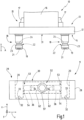
- figure 1 a schematic side view of an embodiment of a workpiece holding device having a carrier plate with a holding device for a workpiece and a clamping device for the carrier plate,
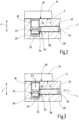
- FIG 2 a partially sectioned representation of the clamping device figure 2 , which shows a clamping body and an associated receiving hole with a clamping bolt arranged therein, the clamping body being in a release position,
- figure 3 the representation figure 2 , whereby the clamping body is in a clamping position
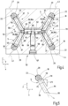
- FIG 4 a schematic representation of the clamping device figure 1 in a cut across the mounting holes
- figure 5 a schematic representation of the force components introduced from a clamping body onto a clamping bolt in a first direction and a second direction
- figure 6 a schematic representation of the alignment of the longitudinal axes of the clamping body and the formation of multiple intersections through the longitudinal axes of the clamping body and
- figure 7 a schematic partial representation of the main body of the clamping device from the figures 1 and 4 in a cross section through a guide channel for a clamping body
- figure 1 shows schematically an exemplary embodiment of a workpiece holding device 10 with a clamping device 11 and a supporting body 12.
- the supporting body 12 has a holding side 13 and, facing away from the holding side 13, an attachment side 14.
- the supporting body 12 can be designed as a supporting plate, with the holding side 13 and the attaching side 14 are formed by the opposite sides of the support plate.
- On the holding side 13 the support body 12 has a holding device 15 for holding a workpiece 16 .
- the holding device 15 can have clamping jaws 17, for example, in order to hold the workpiece 16 in a clamped manner on the support body 12.
- each clamping bolt 18 On the attachment side 14 the support body 12 has a plurality of clamping bolts 18 which protrude from the support body 12 away.
- the clamping bolts 18 are aligned parallel to one another and extend in an axial direction A with respect to the supporting body 12.
- Each clamping bolt 18 can have at least one cylindrical section.
- each clamping bolt 18 At an end facing away from the supporting body 12, each clamping bolt 18 has a chamfer or a conically tapering end section 19.
- each clamping bolt 18 can have an end face recess 21 in the end face.
- Each clamping bolt 18 also has at least one loading surface 22.
- the loading surface 22 extends obliquely inclined to the axial direction A.
- each clamping bolt 18 has exactly one loading surface 22, which is formed by the outer surface of a conical section 23 of the clamping bolt 18.
- the conical section 23 widens in the axial direction A away from the supporting body 12 towards the free end of the clamping bolt 18 .
- the conical section 23 is arranged at a distance from the supporting body 12 and from the end section 19 .
- a tapering section 24 of the clamping bolt 18 can be present between the conical section 23 and the supporting body 12 .
- the tapering section 24 can also be formed by the outer surface of a cone.
- the tapered portion 24 and the conical portion 23 there may be a cylindrical portion.
- the tapering section 24 and the conical section 23 can also merge directly into one another.
- a constriction is formed on the clamping bolt 18 at a distance from the end section 19 and at a distance from the support plate 12 .
- the clamping device 11 has a base body 28.
- the base body 28 has a contact surface 30 on a clamping side 29.
- the contact surface 30 is designed to come into contact with a counter-contact surface 31 on the support body 12 when the support body 12 is attached to the support body 12 by means of the clamping bolts 18
- Tensioning device 11 or the base body 28 is arranged or tensioned.
- Preferably extends the contact surface 30 is in a plane which is spanned by a first direction x and a second direction y.
- the first direction x and the second direction y are related to a coordinate system of the clamping device 11 or the base body 28 . In this coordinate system, a third direction z is oriented perpendicular to the first direction x and to the second direction y.
- the clamping bolts 18 extend approximately in the third direction, e.g.
- the counter-abutment surface 31 preferably extends in a plane which is oriented at right angles to the axial direction A.
- the contact surface 30 and the counter contact surface 31 are set up for surface contact with one another.
- the contact surface 30 or the counter contact surface 31 could have three convex, in particular dome-shaped, elevations on which the respective other surface (i.e. counter contact surface 31 or contact surface 30) bears in a punctiform manner.
- each existing clamping bolt 18 there is an associated receiving hole 20 in the base body 28 which is open towards the clamping side 29 .
- the receiving holes 20 open into the contact surface 30.
- the receiving holes 20 are in the embodiment as Blind holes are formed and closed on the underside of the base body 28 opposite the clamping side 29 by a perforated base 32 in each case.
- An elastically deformable element 33 is optionally arranged on the hole base 32, which projects into the receiving hole and applies a force to an associated clamping bolt 18 in the third direction z when the clamping bolt 18 is completely arranged in the receiving hole 20 and the counter-contact surface 31 is on the contact surface 30 applied.
- the force in the third direction z can be caused by the elastic deformation of the element 33 .
- the elastically deformable element 33 can engage in the end face recess 21 of the associated clamping bolt 18 . This force can simplify the release of the clamping connection between the support body 12 and the clamping device 11 .
- the clamping device 11 has four mounting holes 20.
- the mounting holes 20 form the corner points of a rectangle ( figures 4 and 6 ). Accordingly, four clamping bolts 18 are present on the support body 12, the arrangement and spacing of which corresponds to the arrangement and spacing of the receiving holes 20.
- the clamping device 11 has a plurality of clamping bodies 36 which are arranged in a linearly displaceable manner on and, for example, in the base body 28 .
- Each clamping body 36 is guided in a guide channel 37 and movably mounted.
- the guide channels 37 are introduced into the base body 28, preferably by milling.
- Each guide channel 37 for a clamping body 36 opens into a receiving hole 20.
- the guide channels 37 are groove-shaped and have two opposite channel walls 38, which are connected to one another via a channel base 39 ( figure 7 ).
- the guide channel 37 is open toward the tightening side 29 and, for example, is closed by a cover 40 .
- the cover 40 is arranged in such a way that in the third direction z it does not protrude beyond the plane in which the contact surface 30 or, when the connection to the supporting body 12 has been established, the counter-contact surface 31 extends.
- the outer surface of the cover 40 that is accessible on the tightening side 29 is preferably arranged at a distance from the contact surface 30 .
- the outer surface of the cover 40 that is accessible on the tightening side 29 can form a section of the contact surface 30 .
- the cover 40 is preferably arranged in a cover receptacle 41 following the clamping side 29.
- the cover receptacle 41 forms a depression or recess in the base body 28 and has contact surfaces for the cover 40 in order to be able to attach the cover 40 to the base body 28, for example by means of a screw connection.
- Each channel wall 38 has a guide wall section 42. Outside the respective guide wall section 42, the channel wall 38 extends, for example, in a plane that is aligned parallel to the third direction z in the exemplary embodiment. Outside of the respective guide wall section 42, there is preferably no contact between the clamping body 36 and the channel wall 38. Outside of the guide wall sections 42, there is preferably no contact between the clamping body 36 and the channel base 39 and/or the cover 40.
- the guide wall sections 42 are channel-shaped in the exemplary embodiment. are accordingly the areas of the guided clamping body 36 resting on the guide wall sections 42 are convexly curved. Viewing the channel wall 38 , each guide wall section 42 can be concavely curved with a radius that corresponds to the outer radius of a cylindrical or part-cylindrical section of the clamping body 36 . Due to the two opposing guide wall sections 42 , the clamping body 36 can therefore be arranged in the guide channel 37 so as to be movably guided in the guide wall sections 42 .
- the guide wall sections 42 are preferably formed directly by an area or the material of the base body 28 .
- each clamping body group 50, 51 has exactly two clamping bodies 36.
- a first clamping body 36a and a second clamping body 36b belong to the first clamping body group 50, and a third clamping body 36c and a fourth clamping body 36d belong to the second clamping body group 51.
- the first clamping body 36a has a first Longitudinal axis L1 and is in the associated guide channel 37 along its first longitudinal axis L1 movably mounted.
- the second clamping body 36b has a second longitudinal axis L2 and is movably mounted in the associated guide channel 37 along the second longitudinal axis L2.
- the third clamping body 36c has a third longitudinal axis L3 and is movably mounted in the associated guide channel 37 along the third longitudinal axis L3.
- the fourth clamping body 36d has a fourth longitudinal axis L4 and is movably mounted in the associated guide channel 37 along the fourth longitudinal axis L4.
- each clamping body 36 is between a release position F ( figures 1 and 2 ) and a clamping position S ( Figures 3-5 ) movable.
- the clamping body 36 engages in the associated receiving hole 20 and can act on a clamping bolt 18 arranged there in order to clamp the supporting body 12 with the workpiece 16 on the base body 28 of the clamping device 11 .
- each clamping body 36 has a clamping end 53 assigned to the receiving hole 20 .
- the clamping body 36 has a clamping surface 54 that extends obliquely to the longitudinal axis L of the clamping body 36.
- the clamping surface 54 is also inclined relative to the third direction z and preferably runs parallel to the second direction y.
- the clamping surface 54 can have approximately the same inclination in relation to the third direction z as the action surface 22 has in relation to the axial direction A. As a result, a planar or linear contact can be produced between the clamping surface 54 of the clamping body 36 and the action surface 22 of the clamping bolt 18.
- a clamping body 36 in the clamping position S also exerts a longitudinal force FL on the associated clamping bolt 18, which is aligned along or parallel to the respective longitudinal axis L.
- all longitudinal axes L ie the first longitudinal axis L1, the second longitudinal axis L2, the third longitudinal axis L3 and the fourth longitudinal axis L4 each extend at an angle to the first direction x and the second direction y.
- the longitudinal force FL has a first force component FX in the first direction x and a second force component FY in the second direction y ( figure 5 ).
- each clamping bolt 18 is subjected to both a tensile force FZ in the third direction z and a first force component FX in the first direction x, as well as a second force component FY in applied to the second direction y.
- the clamping bolts 18 are therefore pushed away from one another both in the first direction x and in the second direction y when the clamping bodies 36 are in the clamping position S. This ensures very precise positioning of the support body 12 with the workpiece 16 in the first direction x and the second direction y on the base body 28 of the clamping device 11 .
- the longitudinal axes L of the clamping bodies 36 form a plurality of intersection points arranged at a distance from one another, as is shown schematically in FIG figure 6 is illustrated.
- the third longitudinal axis L3 of the third clamping body 36c and the fourth longitudinal axis L4 of the fourth clamping body 36d both of which belong to the second clamping body group 51, form a second point of intersection P2.
- the first point of intersection P1 and the second point of intersection P2 lie on a common first straight line G1, which extends parallel to the first direction x.
- the first longitudinal axis L1 of the first clamping body 36a and the third longitudinal axis L3 of the third clamping body 36c form a third point of intersection P3.
- the second longitudinal axis L2 of the second clamping body 36b and the fourth longitudinal axis L4 of the fourth clamping body 36d form a fourth point of intersection P4.
- the third point of intersection P3 and the fourth point of intersection P4 are thus formed by longitudinal axes L1 and L3 or L2 and L4, which belong to clamping bodies 36a and 36c or 36b and 36d of different clamping body groups 50 or 51, respectively.
- the third point of intersection P3 and the fourth point of intersection P4 lie on a common second straight line G2, which extends in the second direction y.
- the four points of intersection P1 to P4 form the corner points of a rhombus in one plane parallel to the contact surface 30.
- the distance between the first point of intersection P1 and the second point of intersection P2 is preferably different from the distance between the third point of intersection P3 and the fourth point of intersection P4.
- the two straight lines G1 and G2 intersect at a center point, which also represents the point of intersection of the straight lines connecting the receiving holes 20 .
- the arrangement and alignment of the longitudinal axes L of the clamping bodies 36 and the formation of the points of intersection P1 to P4 can take place independently of other configurations of the clamping device 11 or the tool holding device 10 .
- the actuator 52 preferably has a single source of power to switch all of the clamp members 36 between the release F position and the clamp S position.
- all clamping bodies 36 are in the release position F when one of the clamping bodies 36 is in the release position F and vice versa
- all clamping bodies 36 are in the clamping position S when one of the clamping bodies 36 is in the clamping position S.
- an actuating screw 57 which is rotatably mounted in a nut 58.
- the nut 58 is non-rotatably seated on the base body 28.
- the actuating screw 57 By turning the actuating screw 57, the actuating screw 57 can therefore be displaced along its axis of rotation, which extends in the second direction y in the exemplary embodiment.
- a main body 59 lying against it can be displaced linearly parallel to its extent and, for example, in the second direction y. There is contact between the main body 59 and the actuating screw 57 .
- the actuating screw 57 can be rotated, for example, using a tool.
- the tool can be operated by one operator.
- the tool may also be present on a robotic arm or other piece of machinery.
- the main body 59 has at least one and, in the exemplary embodiment, two main body surfaces 60 oriented obliquely to the second direction y and obliquely to the first direction x.
- the main body tapers in a wedge shape towards its end through the two main body surfaces.
- the main body surfaces 60 are each set up as a contact surface for an actuating body end surface 61 of an actuating body 62 .
- the inclination and orientation of the actuator body end surface 61 of each actuator body 62 is aligned parallel to the main body surface 60 against which the actuator body end surface 61 abuts.
- Each actuator end face 61 is therefore oriented obliquely to the first direction x and obliquely to the second direction y.
- the main body surfaces 60 and the actuator body end surfaces 61 are preferably flat surfaces and extend, for example, parallel to the third direction z.
- the actuating device 52 has an actuating body 62 for each clamping body group 50, 51 that is present.
- two separate actuating bodies 62 are present.
- each actuation body 62 is mounted in a linearly displaceable manner.
- the two actuating bodies 62 are mounted so as to be linearly displaceable in the first direction x.
- the actuating bodies 62 can be arranged along a common axis. At one end they each have the actuating body end surface 61 and at the opposite front end in the first direction x at least one inclined surface 63 .
- each actuating body 62 has two inclined surfaces 63 in the exemplary embodiment.
- the inclined surfaces 63 of an actuating body 62 are each aligned obliquely to the first direction x and the second direction y and are preferably designed as flat surfaces that extend parallel to the third direction z. Due to the two inclined surfaces 63, the actuating body 62 tapers in a wedge shape towards the free end, which is associated with the clamping bodies 36.
- Each tensioning body 36 has, at its actuating end 64 opposite the tensioning end 53 , a tensioning body end surface 65 which is designed to rest against the associated inclined surface 63 .
- the clamping body end surface 65 is inclined to the first direction x and inclined to the second Direction y and, for example, aligned parallel to the third direction z and corresponds in its inclination and orientation to the assigned inclined surface 63.
- the actuating device 52 therefore forms a wedge surface mechanism between the main body 59 and the actuating bodies 62 and between the actuating bodies 62 and the clamping bodies 36.
- the connection between the main body 59 and the actuating bodies 62 is exclusively a contact and cannot transmit any tensile forces.
- the connection between the actuating bodies 62 and the tensioning bodies 36 is a contact and cannot transmit any tensile forces.
- the actuating device 52 is designed without fluid power transmission. It has no fluid components such as pistons or cylinders. According to the example, the actuating device 52 works purely mechanically.
- the tensioning device 11 also has a pretensioning arrangement 70.
- the pretensioning arrangement 70 is set up to pretension or urge the tensioning bodies 36 into their release position F.
- the clamping bodies 36 can be subjected to an elastic force, which pulls or pushes the clamping bodies 36 along their respective longitudinal axis L away from the respective associated receiving hole 20 into the release position F.
- each clamping body group 50, 51 is assigned a prestressing element 71 of the prestressing arrangement 70.
- Two biasing elements 71 are therefore sufficient.
- the prestressing elements 71 are not supported directly on the base body 28 from, but connect the clamping body 36 of the same clamping body group 50 and 51 directly.
- a first biasing element 71 connects the first clamping body 36a to the second clamping body 36b and a second biasing element 71 connects the third clamping body 36c to the fourth clamping body 36d.
- the pretensioning elements 71 produce a tensile force and are fastened to the tensioning bodies 36 in the area of the actuation end.
- the tensile force of the prestressing elements 71 forces the clamping body end surfaces 65 of the clamping bodies 36 of a common clamping body group 50 or 51 against the associated inclined surface 63 of the actuating body 62 which is associated with the clamping body group 50 or 51.
- the main body 59 supports the force acting on the actuating screw 57 .
- the actuating screw 57 supports the force on the base body 28 via the nut 58 .
- the threaded connection between the actuation screw 57 and the nut 58 is self-locking, so that the force acting on the actuation screw 57 in the second direction y cannot cause the actuation screw 57 to move in the second direction y.
- each clamping body 36 a separate biasing element 71, which is on Base body 28 is supported.
- the biasing members 71 may be extension springs, such as coil springs, disposed in recesses of the tension bodies 36 that are open toward the respective actuating end 64 .
- the cutouts are in for the sake of clarity figure 4 not illustrated.
- the actuator 52 operates as follows:
- the actuating bodies 62 are sufficiently close to one another in the first direction x that the clamping bodies 36 lying against them are urged into the release position F by the prestressing arrangement 70 and the receiving holes 20 are released for the insertion of the clamping bolts 18.
- the main body 59 can be moved in the second direction y by actuating the actuating screw 57 and the two actuating bodies 62 can be displaced away from one another. This in turn means that the clamping bodies 36 resting on the inclined surfaces 63 are moved along their respective longitudinal axis L into the associated receiving hole 20 and into the clamping position S.
- the pitch of the screw thread between the actuating screw 57 and the nut 58 means that the actuating device 52 is designed to be self-locking. Regardless of the force exerted on the linearly displaceably mounted main body 59 in the second direction y, the actuating screw 57 remains in its axial position relative to the nut 58 and thus maintains the clamping position S. This is because the mechanical contact between the clamping bodies 36 on the actuating bodies 62 and the actuating bodies 62 on the main body 59 mechanically blocks the release of this clamping position.
- the clamping connection is released by turning the actuating screw 57 in the release direction, whereby the main body 59 can be moved in the second direction y in such a way that the two actuating bodies 62 can move closer together in the first direction x.
- the main body 59 is, so to speak, at least partially moved out of the space between the two actuating bodies 62 .
- the actuating bodies 62 are moved towards one another in the first direction x, which is brought about by the force of the prestressing arrangement 70 and, for example, of the two prestressing elements 71 .
- This in turn means that each clamping body 36 is moved away from the associated receiving hole 20 along its respective longitudinal axis L and can assume its release position F.
- the clamping bolts 18 are not held on the base body 28 by the clamping bodies 36 .
- the optionally present elastically deformable elements 33 have the effect that the clamping bolts 18 are at least approximately pushed out of the receiving holes 20 in order to simplify the removal of the supporting body 12 from the clamping device 11 .
- the guidance of the clamping body 36 in guide channels 37 was explained.
- the at least one actuating body 62 and/or the main body 59 can also be guided in this way. It is thus also possible to provide a guide channel 37 for each existing actuating body 62 or for the example according to the existing main body 59, as can be seen from FIG figure 7 has been described and explained for the or the clamping body 36.
- the invention relates to a clamping device 11 and is set up for releasably clamping a support body 12 on which a workpiece 16 can be arranged.
- the clamping device 11 has a base body 28 with receiving holes 20 for receiving a clamping bolt 18 of the support body 12.
- Each clamping body 36 is linearly movable along its longitudinal axis L between a clamping position S and a release position F. The movement from the release position F to the clamping position S and/or vice versa from the clamping position S to the release position F can take place by means of an actuating device 52 .
- Each clamping body 36 has a clamping end 53 which protrudes into an associated receiving hole 20 in the clamping position S.
- the longitudinal axes of the clamping bodies 36 form a plurality of points of intersection in a common projection plane parallel to which the longitudinal axes L extend. In a preferred embodiment, at least three or four intersections are formed. In particular, there can be four clamping bodies 36, each with a longitudinal axis L, with four intersection points being formed at which two of the existing longitudinal axes L1, L2 or L3, L4 or L1, L3 or L2, L4 intersect.
Description
Die Erfindung betrifft eine Spannvorrichtung für das Spannen eines Tragkörpers. Der Tragkörper kann eine Halteeinrichtung für das Halten eines Werkstücks aufweisen. Mit solchen Spannvorrichtungen können an einem Tragkörper gehaltene Werkstücke in einer Werkzeugmaschine positionsgenau gespannt werden. Insbesondere können in unterschiedlichen Bearbeitungsstationen oder unterschiedlichen Werkzeugmaschinen Spannvorrichtungen vorhanden sein, so dass ein einheitliches Spannen in allen Stationen oder Werkzeugmaschinen ermöglicht ist.The invention relates to a clamping device for clamping a supporting body. The supporting body can have a holding device for holding a workpiece. With such clamping devices, workpieces held on a support body can be clamped in a machine tool in a precisely positioned manner. In particular, clamping devices can be present in different machining stations or different machine tools, so that uniform clamping is made possible in all stations or machine tools.
Eine derartige Spannvorrichtung ist beispielsweise aus
Bei einem Ausführungsbeispiel der aus
Die bekannte Spannvorrichtung hat sich bewährt. Es kann ausgehend vom Stand der Technik als Aufgabe der vorliegenden Erfindung angesehen werden, die Präzision des Spannens zu verbessern und gleichzeitig einen einfachen Aufbau der Spannvorrichtung zu gewährleisten.The well-known clamping device has proven itself. Proceeding from the state of the art, it can be regarded as the object of the present invention to improve the precision of the clamping and at the same time to ensure a simple construction of the clamping device.
Diese Aufgabe wird durch eine Spannvorrichtung mit den Merkmalen des Patentanspruches 1 sowie eine Werkstückhaltevorrichtung mit den Merkmalen des Patentanspruches 15 gelöst.This object is achieved by a clamping device having the features of patent claim 1 and a workpiece holding device having the features of
Die erfindungsgemäße Spannvorrichtung ist für das Spannen eines Tragkörpers eingerichtet. Sie hat einen Grundkörper mit einer Spannseite. An der Spannseite weist der Grundkörper eine Anlagefläche auf. Die Anlagefläche ist dazu eingerichtet, mit einer Gegenanlagefläche des Tragkörpers zur Anlage zu gelangen, wenn der Tragkörper am Grundkörper gespannt ist. Die Anlagefläche kann zusammenhängend sein oder durch mehrere mit Abstand zueinander angeordnete Flächenabschnitte gebildet sein. Die Anlagefläche ist vorzugsweise parallel zu einer Ebene ausgerichtet, die durch eine erste Richtung und eine zweite Richtung aufgespannt ist.The clamping device according to the invention is set up for clamping a supporting body. It has a body with a clamping side. The base body has a contact surface on the clamping side. The contact surface is set up to come into contact with a counter contact surface of the supporting body when the supporting body is clamped on the base body. The contact surface can be continuous or formed by a plurality of surface sections arranged at a distance from one another. The contact surface is preferably aligned parallel to a plane that is spanned by a first direction and a second direction.
An der Spannseite hat der Grundkörper außerdem mehrere zur Spannseite offene Aufnahmelöcher. Die Aufnahmelöcher können in die Anlagefläche münden oder benachbart mit Abstand zur Anlagefläche angeordnet sein. Jedes Aufnahmeloch ist dazu eingerichtet, einen Spannbolzen des Tragkörpers zumindest teilweise aufzunehmen. Vorzugsweise erstrecken sich die Aufnahmelöcher parallel zueinander in einer Richtung rechtwinklig zur Anlagefläche.The base body also has on the clamping side several mounting holes open to the clamping side. The receiving holes can open into the contact surface or be arranged adjacently at a distance from the contact surface. Each receiving hole is set up to at least partially receive a clamping bolt of the supporting body. The receiving holes preferably extend parallel to one another in a direction perpendicular to the contact surface.
Im oder am Grundkörper sind mehrere Spannkörper angeordnet. Vorzugsweise ist jedem Aufnahmeloch genau ein Spannkörper zugeordnet. Die Spannkörper sind entlang ihrer Längsachse linear bewegbar gelagert. Die Spannvorrichtung hat eine Betätigungseinrichtung, die dazu eingerichtet ist, sämtliche Spannkörper zwischen einer Spannstellung und einer Freigabestellung zu bewegen. Jeder Spannkörper hat ein Spannende, das einem der Aufnahmelöcher zugeordnet ist und das in der Spannstellung in das zugeordnete Aufnahmeloch hineinragt. In der Freigabestellung ist jeder Spannkörper weiter von der Mittelachse des Aufnahmelochs entfernt und das Spannende ragt nicht oder weniger weit in das Aufnahmeloch hinein als in der Spannstellung.Several clamping bodies are arranged in or on the base body. Precisely one clamping body is preferably assigned to each receiving hole. The clamping bodies are mounted so that they can move linearly along their longitudinal axis. The clamping device has an actuating device which is set up to move all clamping bodies between a clamping position and a release position. Each clamping body has a clamping end which is assigned to one of the receiving holes and which protrudes into the assigned receiving hole in the clamping position. In the release position, each clamping body is further away from the central axis of the receiving hole and the clamping end does not protrude or protrudes less far into the receiving hole than in the clamping position.
Die Längsachsen der Spannkörper einer gemeinsamen Spannkörpergruppe bilden mehrere Schnittpunkte, insbesondere mindestens drei und vorzugsweise vier Schnittpunkte. Durch die Anordnung der Längsachsen der Spannkörper derart, dass mehrere Schnittpunkte gebildet sind, lässt sich eine sehr genaue Positionierung erreichen. Es lassen sich auch verbleibende Ungenauigkeiten in einem rotatorischen Freiheitsgrad um eine Achse eliminieren, die rechtwinklig zur Anlagefläche ausgerichtet ist. Beim Stand der Technik sind die Längsachsen entweder deckungsgleich oder schneiden sich in einem einzigen Schnittpunkt. Wenn sich aber alle Längsachsen in einem gemeinsamen Punkt schneiden, verbleibt abhängig von der Fertigungsgenauigkeit eine Positionierungenauigkeit um eine Achse, die durch den Schnittpunkt aller Längsachsen der Spannkörper hindurch verläuft.The longitudinal axes of the clamping bodies of a common group of clamping bodies form a plurality of points of intersection, in particular at least three and preferably four points of intersection. By arranging the longitudinal axes of the clamping bodies in such a way that several points of intersection are formed, very precise positioning can be achieved. Remaining inaccuracies in a rotational degree of freedom about an axis that is aligned at right angles to the contact surface can also be eliminated. In the prior art, the longitudinal axes are either congruent or intersect at a single point of intersection. But if all longitudinal axes intersect at a common point, depending on the manufacturing accuracy, there remains a positioning inaccuracy about an axis that runs through the intersection of all longitudinal axes of the clamping bodies.
Die Spannkörper können mehrere Spannkörpergruppen bilden. Die Längsachsen der Spannkörper einer gemeinsamen Spannkörpergruppe können jeweils einen Schnittpunkt bilden. Bei zwei Spannkörpergruppen werden beispielsweise ein erster Schnittpunkt und ein zweiter Schnittpunkt gebildet. Der erste Schnittpunkt und der zweite Schnittpunkt sind vorzugsweise entlang einer sich in einer ersten Richtung erstreckenden Geraden angeordnet.The clamping bodies can form several groups of clamping bodies. The longitudinal axes of the clamping bodies of a common group of clamping bodies can each form an intersection. In the case of two groups of clamping bodies, for example, a first point of intersection and a second point of intersection are formed. The first point of intersection and the second point of intersection are preferably arranged along a straight line extending in a first direction.
Die Längsachse eines Spannkörpers der einen Spannkörpergruppe bildet vorzugsweise mit einer Längsachse eines Spannkörpers der anderen Spannkörpergruppe einen dritten Schnittpunkt. Die Längsachsen zweier anderer Spannkörper dieser Spannkörpergruppen können einen vierten Schnittpunkt bilden. Der dritte Schnittpunkt und der vierte Schnittpunkt können auf einer gemeinsamen Geraden liegen, die vorzugsweise in die zweite Richtung ausgerichtet ist.The longitudinal axis of a clamping body of one group of clamping bodies preferably forms a third point of intersection with a longitudinal axis of a clamping body of the other group of clamping bodies. The longitudinal axes of two other clamping bodies of these clamping body groups can form a fourth point of intersection. The third point of intersection and the fourth point of intersection can lie on a common straight line, which is preferably aligned in the second direction.
Es ist vorteilhaft, wenn mehrere Spannkörpergruppen mit jeweils zwei Spannkörpern vorhanden sind. Beispielsweise kann eine erste Spannkörpergruppe mit einem ersten Spannkörper und einem zweiten Spannkörper vorhanden sein, sowie eine zweite Spannkörpergruppe mit einem dritten Spannkörper und einem vierten Spannkörper. Es ist insbesondere vorteilhaft, wenn die Längsachsen der Spannkörper mindestens vier Schnittpunkte bilden. Vorzugsweise stellen diese vier Schnittpunkte die Ecken eines Polygons dar, das insbesondere die Form einer Raute hat.It is advantageous if there are several clamping body groups, each with two clamping bodies. For example, there can be a first clamping body group with a first clamping body and a second clamping body, and a second clamping body group with a third clamping body and a fourth clamping body. It is particularly advantageous if the longitudinal axes of the clamping bodies form at least four points of intersection. Preferably, these four points of intersection represent the corners of a polygon, which in particular has the shape of a rhombus.
Bei einer bevorzugten Ausführungsform hat jeder Spannkörper ein seinem Spannende entgegengesetztes Betätigungsende, das einem Betätigungskörper der Betätigungseinrichtung zugeordnet ist und bevorzugt an diesem Betätigungskörper anliegt. Der wenigstens eine Betätigungskörper der Betätigungseinrichtung ist vorzugsweise in der ersten Richtung linear bewegbar gelagert. Er ist dazu eingerichtet, die Betätigungsenden mehrerer Spannkörper einer gemeinsamen Spannkörpergruppe zu beaufschlagen. Vorzugsweise weist die Spannkörpergruppe genau zwei Spannkörper auf. Weiter vorzugsweise sind mehrere Spannkörpergruppen und insbesondere genau zwei Spannkörpergruppen vorhanden, denen jeweils ein Betätigungskörper zugeordnet ist. Durch das Verschieben des Betätigungskörpers können die Spannkörper der zugeordneten Spannkörpergruppe ebenfalls verschoben werden, um diese zwischen der Freigabestellung und der Spannstellung umzuschalten. Die Längsachsen der Spannkörper einer gemeinsamen Spannkörpergruppe sind insbesondere weder parallel zueinander, noch deckungsgleich angeordnet. Sie erstrecken sich schräg zueinander und schräg zur ersten Richtung und/oder schräg zur zweiten Richtung. Insbesondere sind zwei Betätigungskörper vorhanden, die jeweils in erster Richtung bewegbar gelagert sind.In a preferred embodiment, each tensioning body has an actuating end opposite its tensioning end, which is assigned to an actuating body of the actuating device and preferably bears against this actuating body. The at least one actuating body of the actuating device is preferably mounted so that it can move linearly in the first direction. It is set up to act on the actuation ends of a plurality of clamping bodies of a common clamping body group. The clamping body group preferably has exactly two clamping bodies. More preferably, there are a plurality of groups of clamping bodies and in particular exactly two groups of clamping bodies, each of which is assigned an actuating body. By moving the actuating body, the clamping bodies of the associated group of clamping bodies can also be moved in order to switch them between the release position and the clamping position. In particular, the longitudinal axes of the clamping bodies of a common group of clamping bodies are neither arranged parallel to one another nor congruently. They extend obliquely to one another and obliquely to the first direction and/or obliquely to the second direction. In particular, two actuating bodies are present, each of which is mounted so that it can move in the first direction.
Mittels des Betätigungskörpers können die Spannkörper zwischen der Freigabestellung und der Spannstellung bewegt werden. In der Spannstellung ist jeder Spannkörper dazu eingerichtet, einen im Aufnahmeloch angeordneten Spannbolzen zu beaufschlagen, insbesondere mit einer Kraft, die Kraftkomponenten rechtwinklig zur Anlagefläche, in die erste Richtung und in die zweite Richtung aufweist.The clamping bodies can be moved between the release position and the clamping position by means of the actuating body. In the clamping position, each clamping body is set up to act on a clamping bolt arranged in the receiving hole, in particular with a force that has force components perpendicular to the contact surface, in the first direction and in the second direction.
Durch diese schräge Ausrichtung der Längsachsen der Spannkörper ist eine einfache Möglichkeit geschaffen, die Spannbolzen mit Kraftkomponenten zu beaufschlagen, die in zwei Raumrichtungen, beispielsgemäß der ersten Richtung und der zweiten Richtung wirken. Dadurch kann der Tragkörper relativ zum Grundkörper in der ersten Richtung und der zweiten Richtung, in der sich die Anlagefläche erstreckt, exakt positioniert werden.This oblique alignment of the longitudinal axes of the clamping bodies creates a simple way of subjecting the clamping bolts to force components that act in two spatial directions, for example the first direction and the second direction. As a result, the support body can be positioned exactly relative to the base body in the first direction and the second direction in which the contact surface extends.
Die Betätigungseinrichtung arbeitet vorzugsweise mechanisch und ist insbesondere frei von fluidischen Kraftübertragungseinheiten. Bevorzugt ist die Kopplung zwischen dem wenigstens einen Betätigungskörper und den zugeordneten Spannkörpern nur eine Druck- oder Schubkräfte übertragende Kopplung und somit keine Zugkräfte übertragende Kopplung. Das heißt, der Betätigungskörper kann die zugeordneten Spannkörper einer gemeinsamen Spannkörpergruppe schiebend beaufschlagen, insbesondere zum Umschalten der Spannkörper in die jeweilige Spannstellung, kann aber keine Zugkraft für eine entgegengesetzte Bewegung ausüben. Insbesondere ist der Betätigungskörper dazu eingerichtet, die zugeordneten Spannkörper von der Freigabestellung in die Spannstellung zu schieben, ohne Zugkopplung zu den Spannkörpern, um diese von der Spannstellung zurück in die Freigabestellung ziehen zu können. Dadurch ergibt sich eine sehr einfache mechanische Ausgestaltung der Betätigungseinrichtung.The actuating device preferably works mechanically and is in particular free of fluid power transmission units. Preferably, the coupling between the at least one actuating body and the associated tensioning bodies is only a coupling that transmits compressive or shearing forces and thus no coupling that transmits tensile forces. This means that the actuating body can push the associated clamping bodies of a common group of clamping bodies, in particular for switching the clamping bodies into the respective clamping position, but cannot exert any tensile force for an opposite movement. In particular, the actuating body is set up to push the associated clamping bodies from the release position into the clamping position, without a tensile coupling to the clamping bodies, in order to be able to pull them back from the clamping position into the release position. This results in a very simple mechanical configuration of the actuating device.
Durch die mechanische Betätigungseinrichtung wird jeder Spannkörper weggesteuert in die jeweilige Spannstellung bewegt. Es kann sichergestellt werden, dass die Verschiebungswege der Spannkörper einer gemeinsamen Spannkörpergruppe gleich groß sind. Zudem lässt sich auch sicherstellen, dass die Verschiebewege sämtlicher Spannkörper in ihre jeweilige Spannstellung gleich groß sind. Dies erhöht die Präzision beim Spannen. Durch das Betätigen der Spannkörper mit wenigstens einem linear verschiebbaren Betätigungskörper und das Vorsehen einer oder mehrerer Spannkörpergruppen können die Aufnahmelöcher problemlos auch mit großem Abstand in der ersten Richtung und/oder der zweiten Richtung voneinander entfernt angeordnet werden. Die Spannkraft wird mechanisch aufrechterhalten. Die Betätigungseinrichtung ist vorzugsweise selbsthemmend. Dadurch wird ein versehentliches Lösen oder Freigeben der Spannkörper bzw. Bewegen der Spannkörper aus ihrer Spannstellung weg verhindert.The mechanical actuating device moves each clamping body into the respective clamping position in a displacement-controlled manner. It can be ensured that the displacement paths of the clamping bodies of a common clamping body group are of the same size. In addition, it can also be ensured that the displacement paths of all clamping bodies in their respective clamping positions are the same. This increases the precision when clamping. By actuating the clamping body with at least one linearly displaceable actuating body and by providing one or more groups of clamping bodies, the receiving holes can also be arranged at a large distance from one another in the first direction and/or the second direction without any problems. The clamping force is maintained mechanically. The actuating device is preferably self-locking. This prevents accidental loosening or release of the clamping bodies or movement of the clamping bodies away from their clamping position.
Vorzugsweise liegt ein Betätigungskörper unmittelbar an den Betätigungsenden der Spannkörper der zugeordneten Spannkörpergruppe an.An actuating body is preferably in direct contact with the actuating ends of the clamping bodies of the associated clamping body group.
Die Betätigungseinrichtung hat vorzugsweise eine einzige Antriebsquelle, beispielsweise ein von einer Bedienperson oder einem Roboter betätigbares Antriebselement, wobei die Antriebsquelle beim Antreiben sämtliche Spannkörper von einer Freigabestellung in die jeweilige Spannstellung bewegen kann. Zwischen dieser Antriebsquelle und den Spannkörpern besteht beispielsweise eine Keilgetriebekopplung.The actuating device preferably has a single drive source, for example a drive element that can be actuated by an operator or a robot, with the drive source being able to move all the clamping bodies from a release position into the respective clamping position when it is driven. For example, there is a wedge gear coupling between this drive source and the clamping bodies.
Es ist außerdem vorteilhaft, wenn wenigstens eines der Aufnahmelöcher in der ersten Richtung mit Abstand von einem der anderen Aufnahmelöcher angeordnet ist und/oder wenigstens eines der Aufnahmelöcher in der zweiten Richtung mit Abstand von einem der anderen Aufnahmelöcher angeordnet ist. Vorzugsweise definieren die Aufnahmelöcher die Ecken eines Polygons. Die Anzahl der Aufnahmelöcher ist insbesondere eine gerade Zahl. Bevorzugt sind vier Aufnahmelöcher vorhanden.It is also advantageous if at least one of the receiving holes is arranged at a distance from one of the other receiving holes in the first direction and/or at least one of the receiving holes is arranged at a distance from one of the other receiving holes in the second direction. Preferably, the receiving holes define the corners of a polygon. The number of mounting holes is especially an even number. There are preferably four receiving holes.
Es ist außerdem vorteilhaft, wenn wenigstens eine Längsachse eines Spannkörpers und insbesondere alle Längsachsen aller Spannkörper schräg zur ersten Richtung und schräg zur zweiten Richtung ausgerichtet sind. Dadurch kann über sämtliche Spannkörper eine Kraft auf die Spannbolzen eingeleitet werden, die eine Kraftkomponente sowohl in der ersten Richtung, als auch in der zweiten Richtung aufweist.It is also advantageous if at least one longitudinal axis of a clamping body and in particular all longitudinal axes of all clamping bodies are aligned obliquely to the first direction and obliquely to the second direction. As a result, a force can be introduced to the clamping bolts via all clamping bodies, which has a force component both in the first direction and in the second direction.
Es ist außerdem vorteilhaft, wenn der wenigstens eine Betätigungskörper ein dem Betätigungsenden der Spannkörper der zugeordneten Spannkörpergruppe zugeordnetes vorderes Ende aufweist. An dem vorderen Ende ist wenigstens eine sich schräg zur ersten Richtung und/oder zur zweiten Richtung erstreckende Schrägfläche vorhanden. Durch diese Schrägfläche kann eine Keilflächengetriebekopplung zwischen dem Betätigungskörper und den mit dem Betätigungskörper in Kontakt stehenden Spannkörpern erreicht werden. Die Anlage zwischen der wenigstens einen Schrägfläche und dem jeweiligen Spannende eines Spannkörpers ist vorzugsweise flächig, kann alternativ aber auch linienförmig oder punktförmig sein.It is also advantageous if the at least one actuating body has a front end associated with the actuating ends of the clamping bodies of the associated group of clamping bodies. At the front end there is at least one inclined surface extending obliquely to the first direction and/or to the second direction. A wedge surface gear coupling between the actuating body and the clamping bodies that are in contact with the actuating body can be achieved by means of this inclined surface. The contact between the at least one inclined surface and the respective clamping end of a clamping body is preferably flat, but can alternatively also be linear or punctiform.
Es ist vorteilhaft, wenn die Betätigungseinrichtung einen Hauptkörper aufweist, der zur Beaufschlagung des wenigstens einen Betätigungskörpers eingerichtet ist. Insbesondere ist der Hauptkörper verschiebbar bzw. linear bewegbar gelagert. Vorzugsweise ist der Hauptkörper in der zweiten Richtung linear bewegbar gelagert.It is advantageous if the actuating device has a main body which is set up to act on the at least one actuating body. In particular, the main body is mounted in a displaceable or linearly movable manner. Preferably, the main body is supported to be linearly movable in the second direction.
Der Hauptkörper kann wenigstens eine sich schräg zur ersten Richtung und/oder zur zweiten Richtung erstreckende Hauptkörperfläche aufweisen. An dieser Hauptkörperfläche kann der wenigstens eine Betätigungskörper vorzugsweise flächig anliegen oder alternativ linienförmig oder punktförmig anliegen.The main body can be at least one inclined have a main body surface extending in the first direction and/or in the second direction. The at least one actuating body can preferably lie flat against this main body surface or alternatively lie in line or in a point-like manner.
Vorzugsweise ist ein einziger Hauptkörper zur Betätigung bzw. Verschiebung sämtlicher vorhandener Betätigungskörper vorhanden. Über den Hauptkörper kann die Umschaltbewegung sämtlicher Spannkörper zwischen der Freigabestellung und der Spannstellung eingeleitet werden.A single main body is preferably provided for actuating or displacing all of the actuating bodies that are present. The switchover movement of all clamping bodies between the release position and the clamping position can be initiated via the main body.
Der Hauptkörper, der wenigstens eine Betätigungskörper und die Spannkörper sind somit linear verschiebbar gelagert entweder in der ersten Richtung oder in der zweiten Richtung oder schräg zur ersten Richtung und zur zweiten Richtung. Diese Betätigungseinrichtung lässt sich sehr einfach in einen plattenförmigen Grundkörper integrieren und ist flach und bauraumsparend ausführbar.The main body, the at least one actuating body and the tensioning body are thus mounted in a linearly displaceable manner either in the first direction or in the second direction or at an angle to the first direction and to the second direction. This actuating device can be integrated very easily into a plate-shaped base body and can be designed to be flat and space-saving.
Die Spannvorrichtung weist einen weiteren erfinderischen Aspekt auf, der unabhängig von den vorstehenden Ausrichtung und Anordnungen der Spannkörper, des wenigstens einen Betätigungskörpers und des Hauptkörpers realisierbar ist. In dem Grundkörper ist dabei wenigstens ein Führungskanal vorhanden, wobei in jedem Führungskanal ein Spannkörper angeordnet ist. Der wenigstens eine Betätigungskörper und/oder der Hauptkörper können zusätzlich auch in jeweils einem weiteren Führungskanal angeordnet sein.The tensioning device has a further inventive aspect that can be implemented independently of the above alignment and arrangements of the tensioning bodies, the at least one actuating body and the main body. At least one guide channel is present in the base body, with a clamping body being arranged in each guide channel. The at least one actuating body and/or the main body can also be arranged in each case in a further guide channel.
Jeder Führungskanal hat zwei sich gegenüberliegende aneinander zugewandte Kanalwände. Vorzugsweise sind die Kanalwände durch sich gegenüberliegende Nutseitenwände gebildet, die innerhalb des Grundkörpers über einen Nutboden miteinander verbunden sind. Gegenüberliegend dem Nutboden ist die Nut offen und vorzugsweise durch einen lösbar am Grundkörper anbringbaren Deckel verschlossen. In jeder Kanalwand ist ein Führungswandabschnitt vorhanden. Der Spannkörper bzw. der Betätigungskörper bzw. der Hauptkörper liegt lediglich im Bereich der beiden sich gegenüberliegenden Führungswandabschnitte am Führungskanal an und ist ansonsten mit Abstand zu den Kanalwänden angeordnet. Vorzugsweise besteht auch ein Abstand zwischen dem Boden und/oder dem Deckel und dem im Führungskanal angeordneten Körper, also dem Spannkörper bzw. dem Betätigungskörper bzw. dem Hauptkörper. Dadurch lässt sich die Reibung zwischen dem Führungskanal und dem jeweils darin verschiebbar angeordneten Körper definiert einstellen bzw. minimieren. Die Kontur des Führungskanals ist daher vorzugsweise lediglich in den Bereichen der Führungswandabschnitte an die Außenkontur des darin verschiebbar gelagerten Körpers (d.h. Spannkörper bzw. Betätigungskörper bzw. Hauptkörper) angepasst. Außerhalb der Führungswandabschnitte kann der Führungskanal eine beliebige Kontur aufweisen und beispielsweise können die Kanalwände außerhalb der Führungswandabschnitte parallel zueinander ausgerichtet sein und sich jeweils parallel zu einer gemeinsamen Mittelebene erstrecken, die sich mittig entlang des Führungskanals erstreckt.Each guide channel has two opposing channel walls facing each other. Preferably, the channel walls are opposed by groove side walls formed, which are connected to each other within the base body via a groove base. Opposite the bottom of the groove, the groove is open and preferably closed by a cover that can be detachably attached to the base body. There is a guide wall section in each channel wall. The clamping body or the actuating body or the main body rests against the guide channel only in the area of the two opposite guide wall sections and is otherwise arranged at a distance from the channel walls. There is preferably also a distance between the base and/or the cover and the body arranged in the guide channel, ie the tensioning body or the actuating body or the main body. As a result, the friction between the guide channel and the body that is displaceably arranged therein can be set or minimized in a defined manner. The contour of the guide channel is therefore preferably only adapted in the areas of the guide wall sections to the outer contour of the body (ie clamping body or actuating body or main body) mounted displaceably therein. Outside the guide wall sections, the guide channel can have any contour and, for example, the channel walls can be aligned parallel to one another outside the guide wall sections and each extend parallel to a common center plane that extends centrally along the guide channel.
Die Führungswandabschnitte können vorzugsweise rinnenförmig ausgebildet sein. Die konkav gekrümmte Rinne kann einen Radius aufweisen, der an den Außenradius eines Außenflächenbereichs des verschiebbar gelagerten Spannkörpers bzw. Betätigungskörpers bzw. Hauptkörpers angepasst ist.The guide wall sections can preferably be designed in the form of channels. The concavely curved channel can have a radius which is adapted to the outer radius of an outer surface area of the displaceably mounted clamping body or actuating body or main body.
Vorzugsweise haben die Spannkörper und/oder Betätigungskörper und/oder Hauptkörper zwischen ihren entgegengesetzten Enden einen zylindrischen Abschnitt, der an den Führungswandabschnitten anliegt.Preferably, the clamping bodies and/or actuating bodies and/or main bodies have a cylindrical portion between their opposite ends which abuts the guide wall portions.
Bei allen vorstehend beschriebenen Ausführungsformen der Spannvorrichtung kann es vorteilhaft sein, wenn eine Vorspannanordnung vorhanden ist. Die Vorspannanordnung kann die Spannkörper in ihre jeweilige Freigabestellung vorspannen bzw. drängen. In ihrer nicht durch den wenigstens einen Betätigungskörper beaufschlagten Ausgangslage nehmen die Spannkörper daher ihre Freigabestellung ein. Vorzugsweise hat die Vorspannanordnung für jede Spannkörpergruppe ein Vorspannelement und insbesondere genau ein Vorspannelement. Das Vorspannelement stützt sich bei einer bevorzugten Ausführungsform unmittelbar an den Spannkörpern der Spannkörpergruppe ab und ist insbesondere nicht unmittelbar am Grundkörper befestigt oder am Grundkörper abgestützt. Bei einem Ausführungsbeispiel bewirkt das Vorspannelement eine Zugkraft zwischen den Spannkörpern der Spannkörpergruppe zum jeweiligen Betätigungskörper hin. Beispielsweise kann das Vorspannelement eine Zugfeder sein. Insbesondere ist die Betätigungseinrichtung ansonsten frei von Vorspannelementen, die ausschließlich an den Spannkörpern angreifen bzw. an den Spannkörpern angeordnet sind.In all of the above-described embodiments of the tensioning device, it can be advantageous if a pretensioning arrangement is present. The biasing arrangement can bias or urge the tensioning bodies into their respective release positions. In their initial position, which is not acted upon by the at least one actuating body, the tensioning bodies therefore assume their release position. The pretensioning arrangement preferably has one pretensioning element and in particular exactly one pretensioning element for each tensioning body group. In a preferred embodiment, the pretensioning element is supported directly on the tensioning bodies of the group of tensioning bodies and is in particular not directly attached to the base body or supported on the base body. In one exemplary embodiment, the pretensioning element causes a tensile force between the tensioning bodies of the tensioning body group towards the respective actuating body. For example, the biasing element can be a tension spring. In particular, the actuating device is otherwise free of pretensioning elements which act exclusively on the tensioning bodies or are arranged on the tensioning bodies.
Eine erfindungsgemäße Werkstückhaltevorrichtung weist eine Spannvorrichtung nach einem der vorstehend beschriebenen Ausführungsbeispiele auf. Außerdem ist ein Tragkörper mit einer Halteseite und einer Anbringungsseite vorhanden. Die Anbringungsseite ist bevorzugt von der Halteseite abgewandt bzw. entgegengesetzt zur Halteseite am Tragkörper vorhanden. Der Tragkörper kann beispielsweise als Tragplatte ausgebildet sein. An der Anbringungsseite ist eine Gegenanlagefläche vorhanden. Die Gegenanlagefläche ist dazu eingerichtet, bei hergestellter Verbindung zwischen dem Tragkörper und der Spannvorrichtung an der Anlagefläche des Grundkörpers anzuliegen. An der Anbringungsseite ragen mehrere Spannbolzen von dem Tragkörper weg. Vorzugsweise erstrecken sich die Spannbolzen parallel zueinander. Die Anzahl der Spannbolzen entspricht insbesondere der Anzahl der Aufnahmelöcher. Bei hergestellter Verbindung ragt jeweils ein Spannbolzen in ein Aufnahmeloch hinein. Das Anordnungsmuster bzw. die Abstände zwischen den Spannbolzen entsprechen daher dem Anordnungsmuster bzw. den Abständen zwischen den Aufnahmelöchern.A workpiece holding device according to the invention has a clamping device according to one of the exemplary embodiments described above. There is also a supporting body with a holding side and an attachment side. The attachment side is preferably facing away from the holding side or opposite to the holding side on the support body. The supporting body can, for example be designed as a support plate. There is a counter contact surface on the attachment side. The counter-abutment surface is designed to lie against the abutment surface of the base body when the connection between the supporting body and the clamping device is established. On the attachment side, a number of clamping bolts protrude from the supporting body. The clamping bolts preferably extend parallel to one another. The number of clamping bolts corresponds in particular to the number of receiving holes. When the connection is made, a clamping bolt protrudes into a receiving hole. The arrangement pattern or the distances between the clamping bolts therefore correspond to the arrangement pattern or the distances between the receiving holes.
Insbesondere hat jeder Spannbolzen eine Beaufschlagungsfläche, die beispielsweise durch eine Konusmantelfläche gebildet sein kann. Die wenigstens eine Beaufschlagungsfläche erstreckt sich schräg zur Erstreckungsrichtung des jeweiligen Spannbolzens. Ist der Spannbolzen im zugeordneten Aufnahmeloch angeordnet, erstreckt sich die Beaufschlagungsfläche schräg zur ersten Richtung und schräg zur zweiten Richtung und schräg zur Erstreckungsrichtung des Spannbolzens. Beaufschlagt der zugeordnete Spannkörper die Beaufschlagungsfläche beim Spannen des Tragkörpers an dem Grundkörper, entstehen Kraftkomponenten in alle drei Raumrichtungen. Rechtwinklig zur ersten Richtung und rechtwinklig zur zweiten Richtung wird die Gegenanlagefläche gegen die Anlagefläche gezogen. Gleichzeitig wird der Spannbolzen durch den Spannkörper in die erste Richtung und die zweite Richtung gedrückt. Die Spannbolzen werden somit parallel zu ihrer Erstreckungsrichtung mit einer Zugkraft beaufschlagt und gleichzeitig voneinander weg in die erste Richtung und die zweite Richtung gedrückt, so dass eine exakte Positionierung und Ausrichtung des Tragkörpers am Grundkörper erfolgt.In particular, each clamping bolt has a loading surface, which can be formed, for example, by a cone surface. The at least one loading surface extends obliquely to the direction of extension of the respective clamping bolt. If the clamping bolt is arranged in the associated receiving hole, the loading surface extends obliquely to the first direction and obliquely to the second direction and obliquely to the direction in which the clamping bolt extends. If the associated tensioning body acts on the action surface when tensioning the supporting body on the base body, force components arise in all three spatial directions. Perpendicular to the first direction and perpendicular to the second direction, the mating surface is pulled against the abutment surface. At the same time, the clamping bolt is pressed in the first direction and the second direction by the clamping body. The clamping bolts are thus subjected to a tensile force parallel to the direction in which they extend and are simultaneously pressed away from one another in the first direction and the second direction, so that a exact positioning and alignment of the support body on the base body takes place.
Vorteilhafte Ausgestaltungen der Erfindung ergeben sich aus den abhängigen Patentansprüchen, der Beschreibung und den Zeichnungen. Nachfolgend werden bevorzugte Ausführungsbeispiele der Erfindung anhand der beigefügten Zeichnungen im Einzelnen erläutert. Es zeigen:Advantageous configurations of the invention result from the dependent patent claims, the description and the drawings. Preferred exemplary embodiments of the invention are explained in detail below with reference to the attached drawings. Show it:
An der Anbringungsseite 14 hat der Tragkörper 12 mehrere Spannbolzen 18, die von dem Tragkörper 12 weg ragen. Beim Ausführungsbeispiel sind die Spannbolzen 18 parallel zueinander ausgerichtet und erstrecken sich in einer Axialrichtung A bezüglich des Tragkörpers 12. Jeder Spannbolzen 18 kann wenigstens einen zylindrischen Abschnitt aufweisen. An einem von dem Tragkörper 12 abgewandten Ende hat jeder Spannbolzen 18 eine Fase bzw. eine sich konisch verjüngenden Endabschnitt 19. Dadurch wird das Einführen des Spannbolzens 18 in ein zugeordnetes Aufnahmeloch 20 der Spannvorrichtung 11 vereinfacht. An dem freien Ende kann jeder Spannbolzen 18 in der Stirnfläche eine Stirnflächenaussparung 21 aufweisen.On the
Jeder Spannbolzen 18 hat außerdem wenigstens eine Beaufschlagungsfläche 22. Die Beaufschlagungsfläche 22 erstreckt sich schräg geneigt zur Axialrichtung A. Beim veranschaulichten Ausführungsbeispiel hat jeder Spannbolzen 18 genau eine Beaufschlagungsfläche 22, die durch die Außenfläche eines konischen Abschnitts 23 des Spannbolzens 18 gebildet ist. Der konische Abschnitt 23 erweitert sich in Axialrichtung A von dem Tragkörper 12 weg zum freien Ende des Spannbolzens 18 hin. Der konische Abschnitt 23 ist beispielsgemäß mit Abstand zum Tragkörper 12 und zum Endabschnitt 19 angeordnet. Zwischen dem konischen Abschnitt 23 und dem Tragkörper 12 kann ein sich verjüngender Abschnitt 24 des Spannbolzens 18 vorhanden sein. Der sich verjüngende Abschnitt 24 kann ebenfalls durch die Außenfläche eines Konus gebildet sein. Zwischen dem sich verjüngenden Abschnitt 24 und dem konischen Abschnitt 23 kann ein zylindrischer Abschnitt vorhanden sein. Alternativ können der sich verjüngende Abschnitt 24 und der konische Abschnitt 23 auch unmittelbar ineinander übergehen. Dadurch ist mit Abstand vom Endabschnitt 19 und mit Abstand zur Tragplatte 12 eine Einschnürung am Spannbolzens 18 gebildet.Each clamping
Die Spannvorrichtung 11 hat einen Grundkörper 28. An einer Spannseite 29 hat der Grundkörper 28 eine Anlagefläche 30. Die Anlagefläche 30 ist dazu eingerichtet, mit einer am Tragkörper 12 vorhandenen Gegenanlagefläche 31 zur Anlage zu gelangen, wenn der Tragkörper 12 mittels der Spannbolzen 18 an der Spannvorrichtung 11 bzw. dem Grundkörper 28 angeordnet bzw. gespannt ist. Vorzugsweise erstreckt sich die Anlagefläche 30 in einer Ebene, die durch eine erste Richtung x und eine zweite Richtung y aufgespannt ist. Die erste Richtung x und die zweite Richtung y sind auf ein Koordinatensystem der Spannvorrichtung 11 bzw. des Grundkörpers 28 bezogen. In diesem Koordinatensystem ist eine dritte Richtung z rechtwinklig zur ersten Richtung x und zur zweiten Richtung y ausgerichtet. Bei hergestellter Verbindung zwischen dem Tragkörper 12 und der Spannvorrichtung 11 erstrecken sich die Spannbolzen 18 in etwa in der dritten Richtung z.The clamping
Die Gegenanlagefläche 31 erstreckt sich vorzugsweise in einer Ebene, die rechtwinklig zur Axialrichtung A ausgerichtet ist. Die Anlagefläche 30 und die Gegenanlagefläche 31 sind zur flächigen Anlage aneinander eingerichtet. Alternativ zu dieser Ausführung ist es auch möglich den Grundkörper 28 und/oder die Tragplatte 12 derart auszugestalten, dass bei hergestellter Verbindung zwischen der Tragplatte 12 und der Spannvorrichtung 11 anstelle einer flächigen Anlage an mehreren Stellen und beispielsweise mindestens oder genau drei mit Abstand zueinander angeordneten Kontaktstellen ein linienhafter oder punktförmiger Kontakt gebildet ist. Zum Beispiel könnte die Anlagefläche 30 oder die Gegenanlagefläche 31 drei konvexe, insbesondere kalottenförmige Erhebungen aufweisen an denen die jeweils andere Fläche (d.h. Gegenanlagefläche 31 bzw. Anlagefläche 30) punktförmig anliegt.The
Für jeden vorhandenen Spannbolzen 18 ist im Grundkörper 28 ein zugeordnetes Aufnahmeloch 20 vorhanden, das zur Spannseite 29 hin offen ist. Beim Ausführungsbeispiel münden die Aufnahmelöcher 20 in die Anlagefläche 30. Die Aufnahmelöcher 20 sind beim Ausführungsbeispiel als Sacklöcher ausgebildet und auf der der Spannseite 29 entgegengesetzten Unterseite des Grundkörpers 28 durch jeweils einen Lochboden 32 geschlossen. Am Lochboden 32 ist optional ein elastisch verformbares Element 33 angeordnet, das in das Aufnahmeloch vorsteht und einen zugeordneten Spannbolzen 18 in der dritten Richtung z mit einer Kraft beaufschlagt, wenn der Spannbolzen 18 vollständig im Aufnahmeloch 20 angeordnet ist und die Gegenanlagefläche 31 an der Anlagefläche 30 anliegt. Die Kraft in die dritte Richtung z kann durch die elastische Verformung des Elements 33 hervorgerufen werden. Das elastisch verformbare Element 33 kann dabei in die Stirnflächenaussparung 21 des zugeordneten Spannbolzens 18 eingreifen. Durch diese Kraft kann das Lösen der Spannverbindung zwischen dem Tragkörper 12 und der Spannvorrichtung 11 vereinfacht werden.For each existing clamping
Die Spannvorrichtung 11 hat beim Ausführungsbeispiel vier Aufnahmelöcher 20. Die Aufnahmelöcher 20 bilden beispielsgemäß die Eckpunkte eines Rechtecks (
Die Spannvorrichtung 11 hat mehrere Spannkörper 36, die linear verschiebbar an und beispielsgemäß in dem Grundkörper 28 angeordnet sind. Jeder Spannkörper 36 ist in einem Führungskanal 37 geführt bewegbar gelagert. Die Führungskanäle 37 sind in den Grundkörper 28 eingebracht, vorzugsweise durch Fräsen. Jeder Führungskanal 37 für einen Spannkörper 36 mündet in ein Aufnahmeloch 20.The clamping
Die Führungskanäle 37 sind beim Ausführungsbeispiel nutförmig und haben zwei sich gegenüberliegende Kanalwände 38, die über einen Kanalboden 39 miteinander verbunden sind (
Jede Kanalwand 38 hat einen Führungswandabschnitt 42. Außerhalb des jeweiligen Führungswandabschnitts 42 erstreckt sich die Kanalwand 38 beispielsgemäß in einer Ebene, die beim Ausführungsbeispiel parallel zur dritten Richtung z ausgerichtet ist. Außerhalb des jeweiligen Führungswandabschnitts 42 besteht vorzugsweise kein Kontakt zwischen dem Spannkörper 36 und der Kanalwand 38. Vorzugsweise besteht außerhalb der Führungswandabschnitte 42 kein Kontakt zwischen dem Spannkörper 36 und dem Kanalboden 39 und/oder dem Deckel 40.Each
Die Führungswandabschnitte 42 sind beim Ausführungsbeispiel rinnenförmig ausgebildet. Entsprechend sind die an den Führungswandabschnitten 42 anliegenden Bereiche des geführten Spannkörpers 36 konvex gekrümmt. Mit Blick auf die Kanalwand 38 kann jeder Führungswandabschnitt 42 mit einem Radius konkav gekrümmt sein, der dem Außenradius eines zylindrischen oder teilzylindrischen Abschnitts des Spannkörpers 36 entspricht. Durch die beiden sich gegenüberliegenden Führungswandabschnitte 42 kann der Spannkörper 36 daher in den Führungswandabschnitten 42 bewegbar geführt im Führungskanal 37 angeordnet sein.The
Die Führungswandabschnitte 42 sind vorzugsweise unmittelbar durch einen Bereich bzw. das Material des Grundkörpers 28 gebildet.The
Es sei an dieser Stelle darauf hingewiesen, dass die Anordnung der Spannkörper 36 in den Führungskanälen 37, wie es vorstehend anhand der
Bei dem hier veranschaulichten Ausführungsbeispiel ist jedem vorhandenen Aufnahmeloch 20 genau ein Spannkörper 36 zugeordnet (
Mittels einer Betätigungseinrichtung 52 der Spannvorrichtung 11 ist jeder Spannkörper 36 zwischen einer Freigabestellung F (
Wie es in
In den
Diese Positionierung wird weiterhin dadurch verbessert und präziser, dass die Längsachsen L der Spannkörper 36 mehrere mit Abstand voneinander angeordnete Schnittpunkte bilden, wie es schematisch in
Beim Ausführungsbeispiel bilden die erste Längsachse L1 des ersten Spannkörpers 36a und die dritte Längsachse L3 des dritten Spannkörpers 36c einen dritten Schnittpunkt P3. Die zweite Längsachse L2 des zweiten Spannkörpers 36b und die vierte Längsachse L4 des vierten Spannkörpers 36d bilden einen vierten Schnittpunkt P4. Der dritte Schnittpunkt P3 und der vierte Schnittpunkt P4 sind somit durch Längsachsen L1 und L3 bzw. L2 und L4 gebildet, die zu Spannkörpern 36a und 36c bzw. 36b und 36d unterschiedlicher Spannkörpergruppen 50 bzw. 51 gehören. Beispielsgemäß liegen der dritte Schnittpunkt P3 und der vierte Schnittpunkt P4 auf einer gemeinsamen zweiten Geraden G2, die sich in die zweite Richtung y erstreckt.In the exemplary embodiment, the first longitudinal axis L1 of the first clamping body 36a and the third longitudinal axis L3 of the third clamping body 36c form a third point of intersection P3. The second longitudinal axis L2 of the second clamping body 36b and the fourth longitudinal axis L4 of the fourth clamping body 36d form a fourth point of intersection P4. The third point of intersection P3 and the fourth point of intersection P4 are thus formed by longitudinal axes L1 and L3 or L2 and L4, which belong to clamping bodies 36a and 36c or 36b and 36d of different
Die vier Schnittpunkte P1 bis P4 bilden beim Ausführungsbeispiel die Eckpunkte einer Raute in einer Ebene parallel zur Anlagefläche 30. Der Abstand zwischen dem ersten Schnittpunkt P1 und dem zweiten Schnittpunkt P2 ist bevorzugt verschieden von dem Abstand zwischen dem dritten Schnittpunkt P3 und dem vierten Schnittpunkt P4.In the exemplary embodiment, the four points of intersection P1 to P4 form the corner points of a rhombus in one plane parallel to the
Beim Ausführungsbeispiel schneiden sich die beiden Geraden G1 und G2 in einem Mittelpunkt, der auch den Schnittpunkt der die Aufnahmelöcher 20 verbindenden Geraden darstellt.In the exemplary embodiment, the two straight lines G1 and G2 intersect at a center point, which also represents the point of intersection of the straight lines connecting the receiving holes 20 .
Durch das Bilden mehrerer Schnittpunkte P1 bis P4 durch die Längsachsen L1 bis L4 der Spannkörper 36 wird auch ein rotativer Freiheitsgrad um eine sich in der dritten Richtung z erstreckenden Achse sehr gut eliminiert und die Positioniergenauigkeit des Tragkörpers 12 gegenüber dem Grundkörper 28 weiter erhöht.By forming several points of intersection P1 to P4 through the longitudinal axes L1 to L4 of the clamping
Die Anordnung und Ausrichtung der Längsachsen L der Spannkörper 36 und die Bildung der Schnittpunkte P1 bis P4 kann unabhängig von anderen Ausgestaltungen der Spannvorrichtung 11 bzw. der Werkzeughaltevorrichtung 10 erfolgen.The arrangement and alignment of the longitudinal axes L of the clamping
Ein Ausführungsbeispiel der Betätigungseinrichtung 52 ist in
Die Betätigungsschraube 57 kann beispielsweise mittels eines Werkzeugs gedreht werden. Das Werkzeug kann von einer Bedienperson bedient werden. Das Werkzeug kann auch an einem Roboterarm oder einer anderen Maschineneinrichtung vorhanden sein.The
An seinem der Betätigungsschraube 57 entgegengesetzten Ende hat der Hauptkörper 59 wenigstens eine und beim Ausführungsbeispiel zwei schräg zur zweiten Richtung y und schräg zur ersten Richtung x ausgerichtete Hauptkörperflächen 60. Der Hauptkörper verjüngt sich durch die beiden Hauptkörperflächen keilförmig zu seinem Ende hin. Die Hauptkörperflächen 60 sind jeweils als Anlagefläche für eine Betätigungskörperendfläche 61 eines Betätigungskörpers 62 eingerichtet. Beispielsgemäß ist die Neigung und Ausrichtung der Betätigungskörperendfläche 61 eines jeweiligen Betätigungskörpers 62 parallel zu der Hauptkörperfläche 60 ausgerichtet, an der die Betätigungskörperendfläche 61 anliegt. Jede Betätigungskörperendfläche 61 ist daher schräg zur ersten Richtung x und schräg zur zweiten Richtung y ausgerichtet. Die Hauptkörperflächen 60 und die Betätigungskörperendflächen 61 sind vorzugsweise ebene Flächen und erstrecken sich beispielsgemäß parallel zur dritten Richtung z.At its end opposite the
Die Betätigungseinrichtung 52 weist für jede vorhandene Spannkörpergruppe 50, 51 einen Betätigungskörper 62 auf. Beim Ausführungsbeispiel sind daher zwei separate Betätigungskörper 62 vorhanden. Jeder Betätigungskörper 62 ist beispielsgemäß linear verschiebbar gelagert. Die beiden Betätigungskörper 62 sind beim Ausführungsbeispiel in die erste Richtung x linear verschiebbar gelagert. Wie es insbesondere in
Jeder Spannkörper 36 hat an seinem dem Spannende 53 entgegengesetzten Betätigungsende 64 eine Spannkörperendfläche 65, die zur Anlage mit der zugeordneten Schrägfläche 63 eingerichtet ist. Die Spannkörperendfläche 65 ist jeweils geneigt zur ersten Richtung x und geneigt zur zweiten Richtung y und beispielsgemäß parallel zur dritten Richtung z ausgerichtet und entspricht in ihrer Neigung und Ausrichtung der zugeordneten Schrägfläche 63.Each
Die Betätigungseinrichtung 52 bildet daher ein Keilflächengetriebe zwischen dem Hauptkörper 59 und dem Betätigungskörpern 62 sowie zwischen den Betätigungskörpern 62 und den Spannkörpern 36. Die Verbindung zwischen dem Hauptkörper 59 und den Betätigungskörpern 62 ist ausschließlich ein Anlagekontakt und kann keine Zugkräfte übertragen. Die Verbindung zwischen den Betätigungskörpern 62 und den Spannkörpern 36 ist ein Anlagekontakt und kann keine Zugkräfte übertragen.The
Die Betätigungseinrichtung 52 ist ohne fluidische Kraftübertragung ausgebildet. Sie weist keine Fluidkomponenten wie Kolben oder Zylinder auf. Die Betätigungseinrichtung 52 arbeitet beispielsgemäß rein mechanisch.The
Die Spannvorrichtung 11 hat außerdem eine Vorspannanordnung 70. Die Vorspannanordnung 70 ist dazu eingerichtet, die Spannkörper 36 in ihre Freigabestellung F vorzuspannen bzw. zu drängen. Dazu können die Spannkörper 36 mit einer elastischen Kraft beaufschlagt werden, die die Spannkörper 36 entlang ihrer jeweiligen Längsachse L vom jeweils zugeordneten Aufnahmeloch 20 weg in die Freigabestellung F zieht oder drückt.The
Bei dem hier gezeigten Ausführungsbeispiel ist jeder Spannkörpergruppe 50, 51 ein Vorspannelement 71 der Vorspannanordnung 70 zugeordnet. Zwei Vorspannelemente 71 sind daher ausreichend. Die Vorspannelemente 71 stützen sich beim Ausführungsbeispiel nicht unmittelbar am Grundkörper 28 ab, sondern verbinden die Spannkörper 36 derselben Spannkörpergruppe 50 bzw. 51 unmittelbar. Somit verbindet ein erstes Vorspannelement 71 den ersten Spannkörper 36a mit dem zweiten Spannkörper 36b und ein zweites Vorspannelement 71 verbindet den dritten Spannkörper 36c mit dem vierten Spannkörper 36d. Die Vorspannelemente 71 bewirken eine Zugkraft und sind im Bereich des Betätigungsendes an den Spannkörpern 36 befestigt. Durch die Zugkraft der Vorspannelemente 71 werden die Spannkörperendflächen 65 der Spannkörper 36 einer gemeinsamen Spannkörpergruppe 50 bzw. 51 gegen die jeweils zugeordnete Schrägfläche 63 des Betätigungskörpers 62 gedrängt, der der Spannkörpergruppe 50 bzw. 51 zugeordnet ist. Dies führt wiederum dazu, dass die Betätigungskörperendflächen 61 der Betätigungskörper 62 gegen die jeweils zugeordnete Hauptkörperfläche 60 des Hauptkörpers 59 gedrängt werden, um die mittels der Vorspannelemente 71 auf die Betätigungskörper 62 wirkende Kraft abzustützen. Der Hauptkörper 59 stützt die einwirkende Kraft an der Betätigungsschraube 57 ab. Die Betätigungsschraube 57 stützt die Kraft über die Mutter 58 am Grundkörper 28 ab. Die Gewindeverbindung zwischen der Betätigungsschraube 57 und der Mutter 58 ist selbsthemmend, so dass die auf die Betätigungsschraube 57 in die zweite Richtung y wirkende Kraft nicht dazu führen kann, dass sich die Betätigungsschraube 57 in der zweiten Richtung y bewegt. Zwischen dem Hauptkörper 59 und den Betätigungskörpern 62 einerseits und zwischen den Betätigungskörpern 62 und den Spannkörpern 36 andererseits besteht daher beim Ausführungsbeispiel stets ein Anlagekontakt.In the exemplary embodiment shown here, each clamping
Alternativ zu der in
Die Betätigungseinrichtung 52 arbeitet wie folgt:The
In einer zurückgezogenen Stellung des Hauptkörpers 59 befinden sich die Betätigungskörper 62 in der ersten Richtung x ausreichend nahe nebeneinander, das die daran anliegenden Spannkörper 36 durch die Vorspannanordnung 70 in die Freigabestellung F gedrängt werden und die Aufnahmelöcher 20 zum Einfügen der Spannbolzen 18 freigeben. Nach dem Anordnen der Spannbolzen 18 in den Aufnahmelöchern 20 kann durch das Betätigen der Betätigungsschraube 57 der Hauptkörper 59 in die zweite Richtung y bewegt werden und die beiden Betätigungskörper 62 voneinander weg verschieben. Dies führt wiederum dazu, dass die an den Schrägflächen 63 anliegenden Spannkörper 36 entlang ihrer jeweiligen Längsachse L in das zugeordnete Aufnahmeloch 20 und in die Spannstellung S bewegt werden. Durch die Steigung des Schraubengewindes zwischen der Betätigungsschraube 57 und der Mutter 58 ist die Betätigungseinrichtung 52 selbsthemmend ausgebildet. Unabhängig von der auf den linear verschiebbar gelagerten Hauptkörper 59 ausgeübten Kraft in die zweite Richtung y, bleibt die Betätigungsschraube 57 gegenüber der Mutter 58 in ihrer axialen Position und hält die Spannstellung S damit aufrecht. Denn durch die mechanische Anlage zwischen den Spannkörpern 36 an den Betätigungskörpern 62 und den Betätigungskörpern 62 am Hauptkörper 59 ist ein Auflösen dieser Spannstellung mechanisch blockiert.In a retracted position of the
Das Lösen der Spannverbindung erfolgt dadurch, dass die Betätigungsschraube 57 in Löserichtung gedreht wird, wodurch sich der Hauptkörper 59 in die zweite Richtung y derart bewegt werden kann, dass ein aneinander annähern der beiden Betätigungskörper 62 in die erste Richtung x möglich ist. Der Hauptkörper 59 wird sozusagen aus dem Zwischenraum zwischen den beiden Betätigungskörpern 62 zumindest teilweise herausbewegt. Dadurch werden die Betätigungskörper 62 in die erste Richtung x aufeinander zu bewegt, was durch die Kraft der Vorspannanordnung 70 und beispielsgemäß der beiden Vorspannelemente 71 bewirkt wird. Dies führt wiederum dazu, dass jeder Spannkörper 36 entlang seiner betreffenden Längsachse L von dem zugeordneten Aufnahmeloch 20 wegbewegt wird und seine Freigabestellung F einnehmen kann.The clamping connection is released by turning the
In der Freigabestellung F werden die Spannbolzen 18 nicht durch die Spannkörper 36 am Grundkörper 28 gehalten. Die optional vorhandenen elastisch verformbaren Elemente 33 bewirken, dass die Spannbolzen 18 aus den Aufnahmelöchern 20 zumindest etwa herausgedrängt werden, um das Entfernen des Tragkörpers 12 von der Spannvorrichtung 11 zu vereinfachen.In the release position F, the clamping
In Bezug auf die
Die Erfindung betrifft eine Spannvorrichtung 11 und ist zum lösbaren Spannen eines Tragkörpers 12 eingerichtet, an dem ein Werkstück 16 angeordnet werden kann. Die Spannvorrichtung 11 hat einen Grundkörper 28 mit Aufnahmelöchern 20 zur Aufnahme jeweils eines Spannbolzens 18 des Tragkörpers 12. Jeder Spannkörper 36 ist entlang seiner Längsachse L zwischen einer Spannstellung S und einer Freigabestellung F linear bewegbar. Das Bewegen von der Freigabestellung F in die Spannstellung S und/oder umgekehrt von der Spannstellung S in die Freigabestellung F kann mittels einer Betätigungseinrichtung 52 erfolgen. Jeder Spannkörper 36 hat ein Spannende 53, das in der Spannstellung S in ein zugeordnetes Aufnahmeloch 20 hineinragt. Die Längsachsen der Spannkörper 36 bilden mehrere Schnittpunkte in einer gemeinsamen Projektionsebene parallel zu der sich die Längsachsen L erstrecken. Bei einem bevorzugten Ausführungsbeispiel sind wenigstens drei oder vier Schnittpunkte gebildet. Insbesondere können vier Spannkörper 36 mit jeweils einer Längsachse L vorhanden sein, wobei vier Schnittpunkte gebildet sind, in denen sich jeweils zwei der vorhandenen Längsachsen L1, L2 bzw. L3, L4 bzw. L1, L3 bzw. L2, L4 schneiden.The invention relates to a
- 1010
- Werkstückhaltevorrichtungworkpiece holding device
- 1111
- Spannvorrichtungclamping device
- 1212
- Tragkörperbody
- 1313
- Halteseiteholding side
- 1414
- Anbringungsseiteattachment side
- 1515
- Halteeinrichtungholding device
- 1616
- Werkstückworkpiece
- 1717
- Klemmbackejaw
- 1818
- Spannbolzenclamping bolt
- 1919
- konischer Endabschnittconical end section
- 2020
- Aufnahmelochreceiving hole
- 2121
- Stirnflächenaussparungface recess
- 2222
- Beaufschlagungsflächeimpingement surface
- 2323
- konischer Abschnittconical section
- 2424
- sich verjüngender Abschnitttapered section
- 2828
- Grundkörperbody
- 2929
- Spannseitetightening side
- 3030
- Anlageflächecontact surface
- 3131
- Gegenanlageflächemating surface
- 3232
- Spannkörperclamping body
- 3333
- elastisch verformbares Elementelastically deformable element
- 3636
- Spannkörperclamping body
- 36a36a
- erster Spannkörperfirst clamping body
- 36b36b
- zweiter Spannkörpersecond clamping body
- 36c36c
- dritter Spannkörperthird clamping body
- 36d36d
- vierter Spannkörperfourth clamping body
- 3737
- Führungskanalguide channel
- 3838
- Kanalwandcanal wall
- 3939
- Kanalbodenchannel bottom
- 4040
- DeckelLid
- 4141
- Deckelaufnahmecover mount
- 4242
- Führungswandabschnittguide wall section
- 4343
- Führungseinsatzleadership
- 5050
- erste Spannkörpergruppefirst clamping body group
- 5151
- zweite Spannkörpergruppesecond clamping body group
- 5252
- Betätigungseinrichtungactuating device
- 5353
- Spannendeexciting
- 5454
- Spannflächeclamping surface
- 5757
- Betätigungsschraubeactuation screw
- 5858
- MutterMother
- 5959
- Hauptkörpermain body
- 6060
- Hauptkörperflächemain body surface
- 6161
- Betätigungskörperendflächeactuator body end face
- 6262
- Betätigungskörperactuating body
- 6363
- Schrägflächebevel
- 6464
- Betätigungsendeactuation end
- 6565
- Spannkörperendflächeclamping body end face
- 7070
- Vorspannanordnungbiasing arrangement
- 7171
- Vorspannelementbiasing element
- AA
- Axialrichtungaxial direction
- Ff
- Freigabestellungrelease position
- FZcar
- Zugkrafttraction
- FLFL
- Längskraftlongitudinal force
- FXfx
- erste Kraftkomponentefirst power component
- FYFY
- zweite Kraftkomponentesecond power component
- G1G1
- erste Geradefirst straight
- G2G2
- zweite Geradesecond straight
- L1L1
- erste Längsachsefirst longitudinal axis
- L2L2
- zweite Längsachsesecond longitudinal axis
- L3L3
- dritte Längsachsethird longitudinal axis
- L4L4
- vierte Längsachsefourth longitudinal axis
- P1P1
- erster Schnittpunktfirst intersection
- P2p2
- zweiter Schnittpunktsecond intersection
- P3P3
- dritter Schnittpunktthird intersection
- P4P4
- vierter Schnittpunktfourth intersection
- SS
- Spannstellungclamping position
- xx
- erste Richtungfirst direction
- yy
- zweite Richtungsecond direction
- ze.g
- dritte Richtungthird direction
Claims (15)
- Clamping device (11) for clamping of a support body (12),having a base body (28) that comprises an abutment surface (30) on a clamping side (29) and that comprises multiple receptacle holes (20) open toward the clamping side (29) that are configured for reception of one clamping bolt (18) of support body (12) in each case,having multiple clamping bodies (36) that are linearly movably supported in or on the base body (28) along its longitudinal axis (L) respectively and that can be moved between a clamping position (S) and a release position (F) by means of an operating device (52),characterized in that the longitudinal axes (L) of clamping bodies (36) define multiple points of intersection (P1, P2, P3, P4).
- Clamping device according to claim 1, characterized in that multiple clamping body groups (50, 51) are provided having at least or exactly two clamping bodies (36) respectively.
- Clamping device according to claim 2, characterized in that the longitudinal axes (L) of clamping bodies (36) define at least or exactly four points of intersection (P1, P2, P3, P4).
- Clamping device according to claim 2 or 3, characterized in that two longitudinal axes (L1, L2) of clamping bodies (36a, 36b) of one of the clamping body groups (50) define a first intersection point (P1) and two longitudinal axes (L3, L4) of clamping bodies (36c, 36d) of another clamping body group (51) define a second intersection point (P2).
- Clamping device according to claim 4, characterized in that the longitudinal axis (L1) of a clamping body (36a) of one of the clamping body groups (50) defines a third intersection point (P3) with the longitudinal axis (L3) of a clamping body (36c) of another clamping body group (51) .
- Clamping device according to claim 5, characterized in that two longitudinal axes (L2, L4) of one clamping body (36b, 36d) respectively of these clamping body groups (50, 51) that do not extend through the third intersection point (P3) define a fourth intersection point (P4).
- Clamping device according to any of the preceding claims, characterized in that the operating device (52) comprises at least one movably supported operating body (62), wherein each operating body (62) is configured to act on operating ends (64) of multiple clamping bodies (36) of a common clamping body group (50, 51), wherein the longitudinal axes (L) of the clamping bodies (36) of a common clamping body group (50, 51) are orientated obliquely to one another.
- Clamping device according to any of the preceding claims, characterized in that at least one of the receptacle holes (20) is arranged with distance in a first direction (x) to one of the other receptacle holes (20) and/or that at least one of the receptacle holes (20) is arranged in a second direction (y) orthogonal to the first direction (x) with distance to one of the other receptacle holes (20).
- Clamping device according to claim 8, characterized in that at least one longitudinal axis (L) of a clamping body (36) or all of the longitudinal axes (L) of clamping bodies (36) extend obliquely to the first direction (x) as well as obliquely to the second direction (y).
- Clamping device according to claim 7, characterized in that the operating device (52) comprises a main body (59) that is configured for acting on the at least one operating body (62).
- Clamping device according to any of the preceding claims, characterized in that base body (28) comprises at least one guide channel (37), wherein one clamping body (36) is arranged in each guide channel and the guide channel (37) comprises a guide wall section (42) on opposite channel walls (38) respectively against which the clamping body (36) abuts and wherein the channel walls (38) are arranged with distance to the clamping body (36) outside of guide wall sections (42).
- Clamping device according to claim 11, characterized in that the channel walls (38) of the at least one guide channel (37) extend parallel to one another outside of guide wall sections (42).
- Clamping device according to claim 11 or 12, characterized in that the guide wall sections (42) are configured in a trough-shaped manner.
- Clamping device according to any of the preceding claims, characterized in that a biasing arrangement (70) is present that urges the clamping body (36) in the respective release position (F).
- Workpiece holding device (10)having a support body (12) supporting a holding device (15) for holding a workpiece (16) on a holding side (13) and that comprises a counter abutment surface (31) and multiple clamping bolts (18) projecting from the support body (12) on an attachment side (14),and having a clamping device (11) according to any of the preceding claims.
Applications Claiming Priority (2)
| Application Number | Priority Date | Filing Date | Title |
|---|---|---|---|
| DE102019116262.9A DE102019116262B4 (en) | 2019-06-14 | 2019-06-14 | Clamping device and workpiece holding device with one clamping device |
| PCT/EP2020/066101 WO2020249621A1 (en) | 2019-06-14 | 2020-06-10 | Clamping device and workpiece holding device with a clamping device |
Publications (2)
| Publication Number | Publication Date |
|---|---|
| EP3983169A1 EP3983169A1 (en) | 2022-04-20 |
| EP3983169B1 true EP3983169B1 (en) | 2023-08-09 |
Family
ID=71111396
Family Applications (1)
| Application Number | Title | Priority Date | Filing Date |
|---|---|---|---|
| EP20733909.4A Active EP3983169B1 (en) | 2019-06-14 | 2020-06-10 | Clamping device and workpiece holding device with a clamping device |
Country Status (4)
| Country | Link |
|---|---|
| US (1) | US11554453B2 (en) |
| EP (1) | EP3983169B1 (en) |
| DE (1) | DE102019116262B4 (en) |
| WO (1) | WO2020249621A1 (en) |
Families Citing this family (5)
| Publication number | Priority date | Publication date | Assignee | Title |
|---|---|---|---|---|
| DE102021100953A1 (en) * | 2021-01-19 | 2022-07-21 | Lang Technik Gmbh | clamping arrangement |
| DE102021100951A1 (en) * | 2021-01-19 | 2022-07-21 | Lang Technik Gmbh | chipboard |
| DE102021117229A1 (en) | 2021-07-05 | 2023-01-05 | Lang Technik Gmbh | Clamping device and method for handling a workpiece |
| DE102021118545A1 (en) | 2021-07-19 | 2023-01-19 | Andreas Maier Gmbh & Co. Kg | clamping device |
| CN113977328A (en) * | 2021-11-10 | 2022-01-28 | 青岛卡沃斯智能制造有限公司 | Tank track movable support technological equipment system |
Family Cites Families (10)
| Publication number | Priority date | Publication date | Assignee | Title |
|---|---|---|---|---|
| JPS5973622A (en) * | 1982-10-19 | 1984-04-25 | Nobuyuki Tsuboi | Slide bearing |
| US5167405A (en) | 1991-08-21 | 1992-12-01 | Midaco Corporation | Fast change set-up device for work on work support |
| DE10155077B4 (en) * | 2001-11-09 | 2004-07-29 | Lang, Günter | Repeatable clamping device |
| DE102010010898C5 (en) * | 2010-03-05 | 2017-04-13 | Schunk Gmbh & Co. Kg | Pallet System |
| DE102014112843B4 (en) * | 2014-09-05 | 2019-05-09 | Jochen Eggert | Zero-point clamping system |
| DE102016009895A1 (en) * | 2016-08-13 | 2018-02-15 | Sauter Feinmechanik Gmbh | Device for releasably fixing modules |
| US10603750B1 (en) * | 2017-04-04 | 2020-03-31 | Jergens, Inc. | Mounting system with self aligning cam system |
| US9902033B1 (en) * | 2017-06-08 | 2018-02-27 | Chris Taylor | Tooling base |
| DE202018105390U1 (en) | 2018-09-20 | 2018-09-28 | Wen-Hsiang Chou | A simple positioning enabling changing device |
| ES2899073T3 (en) * | 2019-05-20 | 2022-03-10 | Smw Autoblok Spannsysteme Gmbh | Zero point clamping device |
-
2019
- 2019-06-14 DE DE102019116262.9A patent/DE102019116262B4/en active Active
-
2020
- 2020-06-10 US US17/619,042 patent/US11554453B2/en active Active
- 2020-06-10 WO PCT/EP2020/066101 patent/WO2020249621A1/en active Application Filing
- 2020-06-10 EP EP20733909.4A patent/EP3983169B1/en active Active
Also Published As
| Publication number | Publication date |
|---|---|
| EP3983169A1 (en) | 2022-04-20 |
| DE102019116262A1 (en) | 2020-12-17 |
| US20220212299A1 (en) | 2022-07-07 |
| WO2020249621A1 (en) | 2020-12-17 |
| US11554453B2 (en) | 2023-01-17 |
| DE102019116262B4 (en) | 2021-11-18 |
Similar Documents
| Publication | Publication Date | Title |
|---|---|---|
| EP3983169B1 (en) | Clamping device and workpiece holding device with a clamping device | |
| DE10155077B4 (en) | Repeatable clamping device | |
| DE3610317C2 (en) | ||
| EP0595074B1 (en) | Clamping device | |
| EP0742081A2 (en) | Universal precision vice for a machine tool | |
| DE102014119482A1 (en) | Tool clamping device | |
| EP3263274A1 (en) | Clamping device and clamping system | |
| EP0201456B1 (en) | Press with an upper and a lower plate for fixing a tool set | |
| EP1955816A2 (en) | Clamping device | |
| EP3851249B1 (en) | Workpiece clamping device | |
| EP0870580B1 (en) | Vice | |
| EP0362753B1 (en) | Clamping device | |
| EP1775102A2 (en) | Quick changing device for the vibrating tool of a vibration welding machine | |
| DE102019108737B3 (en) | Arrangement comprising a clamping device and method for clamping a workpiece | |
| EP3620260B1 (en) | Compensation device for compensating for a positioning tolerance | |
| EP3616831A1 (en) | Clamping device | |
| EP1904256A1 (en) | Chuck and rotary orienting device | |
| EP0641623B1 (en) | Clamping device for holding workpieces | |
| DE102021103905B4 (en) | Clamping unit and clamping system with at least one clamping unit | |
| DE3822434C2 (en) | ||
| DE3400813C2 (en) | ||
| EP3484659B1 (en) | Clamping device | |
| CH692486A5 (en) | Mehrfachaufspannvorrichtung for workpieces. | |
| EP3366417B1 (en) | Pull bolt of a zero point clamping system | |
| EP0671227B1 (en) | Tool clamping device for a bending press |
Legal Events
| Date | Code | Title | Description |
|---|---|---|---|
| STAA | Information on the status of an ep patent application or granted ep patent |
Free format text: STATUS: UNKNOWN |
|
| STAA | Information on the status of an ep patent application or granted ep patent |
Free format text: STATUS: THE INTERNATIONAL PUBLICATION HAS BEEN MADE |
|
| PUAI | Public reference made under article 153(3) epc to a published international application that has entered the european phase |
Free format text: ORIGINAL CODE: 0009012 |
|
| STAA | Information on the status of an ep patent application or granted ep patent |
Free format text: STATUS: REQUEST FOR EXAMINATION WAS MADE |
|
| 17P | Request for examination filed |
Effective date: 20211220 |
|
| AK | Designated contracting states |
Kind code of ref document: A1 Designated state(s): AL AT BE BG CH CY CZ DE DK EE ES FI FR GB GR HR HU IE IS IT LI LT LU LV MC MK MT NL NO PL PT RO RS SE SI SK SM TR |
|
| DAV | Request for validation of the european patent (deleted) | ||
| DAX | Request for extension of the european patent (deleted) | ||
| GRAP | Despatch of communication of intention to grant a patent |
Free format text: ORIGINAL CODE: EPIDOSNIGR1 |
|
| STAA | Information on the status of an ep patent application or granted ep patent |
Free format text: STATUS: GRANT OF PATENT IS INTENDED |
|
| INTG | Intention to grant announced |
Effective date: 20230203 |
|
| GRAS | Grant fee paid |
Free format text: ORIGINAL CODE: EPIDOSNIGR3 |
|
| GRAA | (expected) grant |
Free format text: ORIGINAL CODE: 0009210 |
|
| STAA | Information on the status of an ep patent application or granted ep patent |
Free format text: STATUS: THE PATENT HAS BEEN GRANTED |
|
| AK | Designated contracting states |
Kind code of ref document: B1 Designated state(s): AL AT BE BG CH CY CZ DE DK EE ES FI FR GB GR HR HU IE IS IT LI LT LU LV MC MK MT NL NO PL PT RO RS SE SI SK SM TR |
|
| REG | Reference to a national code |
Ref country code: GB Ref legal event code: FG4D Free format text: NOT ENGLISH |
|
| REG | Reference to a national code |
Ref country code: CH Ref legal event code: EP |
|
| REG | Reference to a national code |
Ref country code: IE Ref legal event code: FG4D Free format text: LANGUAGE OF EP DOCUMENT: GERMAN |
|
| REG | Reference to a national code |
Ref country code: DE Ref legal event code: R096 Ref document number: 502020004649 Country of ref document: DE |
|
| REG | Reference to a national code |
Ref country code: LT Ref legal event code: MG9D |
|
| REG | Reference to a national code |
Ref country code: NL Ref legal event code: MP Effective date: 20230809 |
|
| PG25 | Lapsed in a contracting state [announced via postgrant information from national office to epo] |
Ref country code: GR Free format text: LAPSE BECAUSE OF FAILURE TO SUBMIT A TRANSLATION OF THE DESCRIPTION OR TO PAY THE FEE WITHIN THE PRESCRIBED TIME-LIMIT Effective date: 20231110 |
|
| PG25 | Lapsed in a contracting state [announced via postgrant information from national office to epo] |
Ref country code: IS Free format text: LAPSE BECAUSE OF FAILURE TO SUBMIT A TRANSLATION OF THE DESCRIPTION OR TO PAY THE FEE WITHIN THE PRESCRIBED TIME-LIMIT Effective date: 20231209 |
|
| PG25 | Lapsed in a contracting state [announced via postgrant information from national office to epo] |
Ref country code: SE Free format text: LAPSE BECAUSE OF FAILURE TO SUBMIT A TRANSLATION OF THE DESCRIPTION OR TO PAY THE FEE WITHIN THE PRESCRIBED TIME-LIMIT Effective date: 20230809 Ref country code: RS Free format text: LAPSE BECAUSE OF FAILURE TO SUBMIT A TRANSLATION OF THE DESCRIPTION OR TO PAY THE FEE WITHIN THE PRESCRIBED TIME-LIMIT Effective date: 20230809 Ref country code: PT Free format text: LAPSE BECAUSE OF FAILURE TO SUBMIT A TRANSLATION OF THE DESCRIPTION OR TO PAY THE FEE WITHIN THE PRESCRIBED TIME-LIMIT Effective date: 20231211 Ref country code: NO Free format text: LAPSE BECAUSE OF FAILURE TO SUBMIT A TRANSLATION OF THE DESCRIPTION OR TO PAY THE FEE WITHIN THE PRESCRIBED TIME-LIMIT Effective date: 20231109 Ref country code: NL Free format text: LAPSE BECAUSE OF FAILURE TO SUBMIT A TRANSLATION OF THE DESCRIPTION OR TO PAY THE FEE WITHIN THE PRESCRIBED TIME-LIMIT Effective date: 20230809 Ref country code: LV Free format text: LAPSE BECAUSE OF FAILURE TO SUBMIT A TRANSLATION OF THE DESCRIPTION OR TO PAY THE FEE WITHIN THE PRESCRIBED TIME-LIMIT Effective date: 20230809 Ref country code: LT Free format text: LAPSE BECAUSE OF FAILURE TO SUBMIT A TRANSLATION OF THE DESCRIPTION OR TO PAY THE FEE WITHIN THE PRESCRIBED TIME-LIMIT Effective date: 20230809 Ref country code: IS Free format text: LAPSE BECAUSE OF FAILURE TO SUBMIT A TRANSLATION OF THE DESCRIPTION OR TO PAY THE FEE WITHIN THE PRESCRIBED TIME-LIMIT Effective date: 20231209 Ref country code: HR Free format text: LAPSE BECAUSE OF FAILURE TO SUBMIT A TRANSLATION OF THE DESCRIPTION OR TO PAY THE FEE WITHIN THE PRESCRIBED TIME-LIMIT Effective date: 20230809 Ref country code: GR Free format text: LAPSE BECAUSE OF FAILURE TO SUBMIT A TRANSLATION OF THE DESCRIPTION OR TO PAY THE FEE WITHIN THE PRESCRIBED TIME-LIMIT Effective date: 20231110 Ref country code: FI Free format text: LAPSE BECAUSE OF FAILURE TO SUBMIT A TRANSLATION OF THE DESCRIPTION OR TO PAY THE FEE WITHIN THE PRESCRIBED TIME-LIMIT Effective date: 20230809 |
|
| PG25 | Lapsed in a contracting state [announced via postgrant information from national office to epo] |
Ref country code: PL Free format text: LAPSE BECAUSE OF FAILURE TO SUBMIT A TRANSLATION OF THE DESCRIPTION OR TO PAY THE FEE WITHIN THE PRESCRIBED TIME-LIMIT Effective date: 20230809 |